1
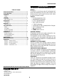
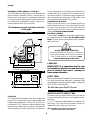
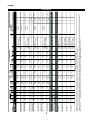
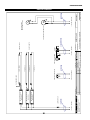
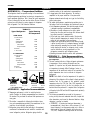
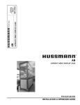
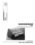
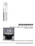
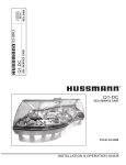
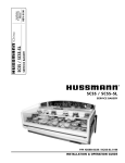
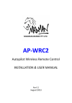
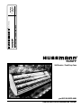
RGSSFP
Rev.0008
Installation
& Operation
Manual
/Chino
Self Service / Food Prep Case
RGSSFP
Self Service / Food Prep Case
p/n IGFP-RGSSFP-0008
INSTALLATION & OPERATION GUIDE
IGFP-RGSSFP-0008
General Instructions
THIS BOOKLET CONTAINS INFORMATION ON:
RGSSFP
Table of Contents
The RGSSFP is a food prep case with refrigerated selfservice merchandising in the front, and hot and/or cold
food prep area on top. Its large food prep counter makes
for easy working and cleaning.
General Instructions ................................................. 2
Cut & Plan Views ....................................................... 3
Installation ................................................................. 3
LEVELING.............................................................................................................. 3
JOINT TRIM ........................................................................................................... 3
Plumbing ................................................................... 3
WASTE OUTLET AND P-TRAP .............................................................................. 3
Refrigeration ............................................................. 4
T-STAT LOCATION .................................................................................................. 5
Electrical .................................................................... 5
WIRING COLOR CODE ......................................................................................... 5
User Information ...................................................... 6
STOCKING.............................................................................................................. 6
CASE CLEANING .................................................................................................... 6
NON-GLARE GLASS CLEANING ............................................................................. 7
PLEXIGLASS & ACRYLIC CARE .............................................................................. 7
Maintenance .............................................................. 8
ELECTRICAL PRECAUTIONS ................................................................................... 8
REPLACING FLUORESCENT LAMPS ....................................................................... 8
TIPS & TROUBLESHOOTING ................................................................................. 8
Specifications ............................................................. 9
Electrical Schematics ............................................... 10
Appendices ................................................................ 15
APPENDIX A. – Temperature Guidlines .............................................................. 15
APPENDIX B. – Application Recommendations .................................................. 15
APPENDIX C. – Field Recommendations ............................................................ 15
APPENDIX D. – Recommendations to user ....................................................... 16
Features:
•
•
•
•
•
•
•
•
•
Curved plexiglass lower front
StainlessSteel food prep area
8” & 12” Adjustable Shelves
Solar Digital thermometer
1” Black Vinyl bumper
Condensing Unit (Self Contained) with Air-Evap pan
115V Convenience Outlet
UL listed SA7576S
CRMA listed CRS-S1-96
SHIPPING DAMAGE
All equipment should be thoroughly examined for shipping damage before and during unloading.
This equipment has been carefully inspected at our factory and the carrier has assumed responsibility for safe
arrival. If damaged, either apparent or concealed, claim must
be made to the carrier.
APPARENT LOSS OR DAMAGE
If there is an obvious loss or damage, it must be noted on
the freight bill or express receipt and signed by the carrier’s
agent; otherwise, carrier may refuse claim.The carrier will
supply necessary claim forms.
CONCEALED LOSS OR DAMAGE
When loss or damage is not apparent until after equipment
is uncrated, a claim for concealed damage is made. Make
request in writing to carrier for inspection within 15 days,
and retain all packaging. The carrier will supply inspection
report and required claim forms.
SHORTAGES
Check your shipment for any possible shortages of material. If a shortage should exist and is found to be the responsibility of Hussmann Chino, notify Hussmann Chino. If
such a shortage involves the carrier, notify the carrier immediately, and request an inspection. Hussmann Chino will
acknowledge shortages within ten days from receipt of
Keep this booklet with the case at all times for future reference. equipment.
/Chino
A publication of
Hussmann® Chino
13770 Ramona Avenue • Chino, California 91710
(909) 628-8942 FAX
(909) 590-4910
(800) 395-9229
2
Rev.0008
HUSSMANN CHINO PRODUCT CONTROL
Product temperature should always be maintained at a
constant and proper temperature. This means that from
the time the product is received, through storage, preparation and display, the temperature of the product must
be controlled to maximize life of the product.
The serial number and shipping date of all equipment has
been recorded in Hussmann’s files for warranty and replacement part purposes. All correspondence pertaining
to warranty or parts ordering must include the serial number of each piece of equipment involved, in order to provide the customer with the correct parts.
UNCRATING THE STAND
Place the fixture as close to its permanent position as
possible. Remove the top of the crate. Detach the walls
from each other and remove from the skid. Unbolt the
case from the skid. The fixture can now be lifted off the
crate skid. Lift only at base of stand!
The Hussmann warranty is printed on the back
of this guide.
Cut & Plan Views
EXTERIOR LOADING
13"
Light
Ref. Dome
(Optional)
End
Panel
9 7/8"
Coil
AVOID REMOVING CONCRETE
All cases were leveled and joined prior to shipment to
ensure closest possible fit when cases are joined in the
field. To avoid removing concrete flooring, begin
lineup at highest point of store floor.
*36"
8"
12"
19 1/2"
Condensing
Unit
S.C.
Adj. Wire
Racks
Elec.
Access
*5"
*12"
These models have not been structurally designed to support excessive external loading. Do not walk on their
tops; This could cause serious personal injury and damage to the fixture.
30"
12"
LEVELING
IMPORTANT! It is imperative that the case
be leveled from front to back and side to side
prior to joining. A level case is necessary to
insure proper operation.
8 1/4"
48"
RGSSFP (S.C)
8"
shown with Optional Refrigerated Rear Storage
Prep/Self-Service
In16"
CONDENSING
UNIT
JOINT TRIM
After the case has been leveled and joined, and refrigeration, electrical, and waste piping work completed, install
the splashguards. Fasten along the top edge, or center, with
#10 X 3/8" sheet metal screws.
16"
48"
REFRIG.
MECHANICAL
STUB UP AREA
none
DRAIN & ELEC.
MECHANICAL
STUB UP AREA
18" X 18"
CASE FRONT
1"
8"
8’-2" (4’-2”, 6’-2”)
8"
1"
Plan View
DO NOT SEAL JOINT TRIM TO FLOOR!
Plumbing
WASTE OUTLET AND P-TRAP
stallation
The waste outlet is located off the center of the case on
one side allowing drip piping to be run lengthwise under
the fixture.
A 1-1/2" P-trap and threaded adapter are supplied with
each fixture. The P-trap must be installed to prevent air
leakage and insect entrance into the fixture.
LOCATION
The refrigerated merchandisers have been designed for
use only in air conditioned stores where temperature and
humidity are maintained at or below 75°F and 55% relative humidity. DO NOT allow air conditioning, electric fans,
open doors or windows (etc.) to create air currents around
the merchandiser, as this will impair its correct operation.
NOTE: PVC-DWV solvent cement is recommended.
Follow the manufacturer’s instructions.
3
IGFP-RGSSFP-0008
INSTALLING CONDENSATE DRAIN
REFRIGERATION LINES
LIQUID
SUCTION
Poorly or improperly installed condensate drains can seriously interfere with the operation of this refrigerator,
and result in costly maintenance and product losses. Please
follow the recommendations listed below when installing
condensate drains to insure a proper installation:
1. Never use pipe for condensate drains smaller than
the nominal diameter of the pipe or P-trap supplied
with the case.
2. When connecting condensate drains, the P-trap
must be used as part of the condensate drain to
prevent air leakage or insect entrance. Store plumbing system floor drains should be at least 14" off the
center of the case to allow use of the P-trap pipe
section. Never use two water seals in series in any
one line. Double P-traps in series will cause a lock
and prevent draining.
3. Always provide as much down hill slope (“fall”) as
possible; 1/8" per foot is the preferred minimum.
PVC pipe, when used, must be supported to maintain the 1/8" pitch and to prevent warping.
4. Avoid long runs of condensate drains. Long runs
make it impossible to provide the “fall” necessary for
good drainage.
3/8" O.D.
5/8" O.D.
NOTE: The standard coil is piped at 5/8" (suction); however,
the store tie-in may vary depending on the number of
coils and the draw the case has. Depending on the case
setup, the connecting point in the store may be
5
/8", 7/8", or 11/8". Refer to the particular case you are
hooking up.
Refrigerant lines should be sized as shown on the refrigeration legend furnished by the store.
Install P-traps (oil traps) at the base of all suction line vertical risers.
Pressure drop can rob the system of capacity. To keep the
pressure drop to a minimum, keep refrigerant line run as
short as possible, using the minimum number of elbows.
Where elbows are required, use long radius elbows only.
CONTROL SETTINGS
See the “Case Specs” section of this guidebook for the
appropriate settings for your merchandiser. Maintain these
parameters to achieve near constant product temperatures. Product temperature should be measured first thing
in the morning, after having been refrigerated overnight.
For all multiplexing, defrost should be time terminated.
Loadmaster valves are not recommended. Defrost times
should be as follows: OFF CYCLE - Three times daily for
46 minutes.The number of defrosts per day and the duration of the defrost cycle may be adjusted to meet conditions present at your location.
5. Provide a suitable air break between the flood rim of
the floor drain and outlet of condensate drain. 1" is
ideal.
6. Prevent condensate drains from freezing:
a. Do not install condensate drains in contact with
non-insulated suction lines. Suction lines should be
insulated with a nonabsorbent insulation material
such as Armstrong’s Armaflex.
b. Where condensate drains are located in dead air
spaces (between refrigerators or between a
refrigerator and a wall), provide means to prevent
freezing.The water seal should be insulated to
prevent condensation.
ACCESS TO TX VALVES & DRAIN LINES
MECHANICAL - Remove the product from the bottom deck
pan. Remove pan. Remove refrigeration and drain access panels (labeled). TX valve (mechanical only) and drain are located under each access panel at end of the case.
ELECTRONIC (Remote Only) - The Electronic Expansion valve
controller is located within the electrical access panel(s).
ELECTRONIC EXPANSION VALVE (Remote Only)
A wide variety of electronic expansion valves and case
controllers can be utilized. Please refer to EEV and controller manufacturers information sheet. Sensors for electronic expansion valves will be installed on the coil inlet,
coil outlet, and in the discharge air. (Some supermarkets
require a 4th sensor in the return air). Case controllers
will be located in the electrical raceway or under the case
Refrigeration
REFRIGERANT TYPE
The standard refrigerant will be R-22 unless otherwise
specified on the customer order. Check the serial plate
on the case for information.
THERMOSTATIC EXPANSION VALVE LOCATION
This device is located on the same side as the refrigeration stub. A Sporlan balanced port expansion valve model
is furnished as standard equipment, unless otherwise specified by customer.
PIPING - Remote Cases Only
The refrigerant line outlets are located under the case.
Locate first the electrical box, the outlets are then on the
same side of the case but at the opposite end. Insulate
suction lines to prevent condensation drippage.
4
Rev.0008
EXPANSION VALVE ADJUSTMENT
Electrical
Expansion valves must be adjusted to fully feed the evaporator. Before attempting any adjustments, make sure the
evaporator is either clear or very lightly covered with frost,
and that the fixture is within 10°F of its expected operating temperature.
WIRING COLOR CODE
Self Contained cases are wired using a terminal block.
Remote cases are
follows:
S TA Nwired
DA R D C Aas
SE W
IRE COLOR CODE
C O D I G O D E C O L O R E S D E L O S A L A M B R E S PA R A L A S V I T R I N A S E S TA N DA R
CODE COULEUR POUR FILS DE BOITIER NORMALISE
Color Description
MEASURING THE OPERATING SUPERHEAT
1. Determine the suction pressure with an accurate
pressure gauge at the evaporator outlet.
2. From a refrigerant pressure temperature chart,
determine the saturation temperature at the
observed suction pressure.
3. Measure the temperature of the suction gas at the
thermostatic remote bulb location.
4. Subtract the saturation temperature obtained in step
No. 2 from the temperature measured in step No. 3.
3. The difference is superheat.
5. Set the superheat for 5°F - 7°F.
Descripcion
Descripcion
G RO U N D
TIERRA MASA
MASSE
A N T I - S W E AT
ANTICONDENSCION
ANTI-SUINTEMENT
LIGHTS
LUCES
ECLAIRAGE
R E C E P TA C L E S
ENCHUFER
R E C E P TA C L E
T-STAT/SOLENOID 230 V THERMOSTATO / SOLENOID (230 VAC)
SOUPAPE A SOLENOID (230 V)
T-STAT/SOLENOID 115 V THERMOSTATO / SOLENOID (115 VAC)
SOUPAPE A SOLENOID (115 V)
FAN MOTORS
VENTILATEUR
VENTILADORES
C
E
A
S
430-01-0338 r9908
MUST BE GROUNDED
NOTE: Refer to label affixed to case to determine the actual
configuration as checked in the “TYPE INSTALLED” boxes.
ELECTRICAL CIRCUIT IDENTIFICATION
Standard lighting for all models will be full length fluorescent lamps located within the case at the top.
The switch controlling the lights, the plug provided for
digital scale, and the thermometer are located at the rear
of the case mullion.
The receptacle that is provided on the exterior back of
these models is intended for computerized scales with a
five amp maximum load, not for large motors or other
high wattage appliances. It should be wired to a dedicated
circuit.
NOTE: Slow air picks up more humidity from coil and ice.
T-STAT LOCATION
T-Stats are located within the electrical raceway. at the front
of the case.
Locations for Ballast, T-Stat and Electrical
Light
Ref. Dome
(Optional)
ELECTRICAL SERVICE RECEPTACLES
(When Applicable)
The receptacles located on the exterior of the merchandiser are intended for scales and lighted displays.They
are not intended nor suitable for large motors or other
external appliances.
Coil
Condensing
Unit (S.C.)
ELEC. ACCESS
T-STAT &
BALLAST
Optional Electrical
Access T-Stat and
BEFORE SERVICING
ALWAYS DISCONNECT ELECTRICAL
POWER AT THE MAIN DISCONNECT
WHEN SERVICING OR REPLACING ANY
ELECTRICAL COMPONENT.
This includes (but not limited to) Fans, Heaters, Thermostats, and Lights.
FIELD WIRING & SERIAL PLATE AMPERAGE
Field Wiring must be sized for component amperes printed
on the serial plate. Actual ampere draw may be less than
5
IGFP-RGSSFP-0008
specified. Field wiring from the refrigeration control panel
to the merchandisers is required for refrigeration thermostats. Most component amperes are listed in the “Case
Specs” section, but always check the serial plate.
mum visibility and product life at the factory.The use
of higher output fluorescent lamps (H.O. and V.H.O.),
will shorten the shelf life of the product.
IMPORTANT STEPS
1. Do not set temperature too cold, as this causes
product dehydration. Product Temperature:
33°–35°!
Set thermostat to cut in at 28° discharge air. Meat
holding box: 32°. Meat prep room: 55°. Meat bloom
box: 36°.
Process the meat to enter case at 40° or below.
Product deterioration is very rapid above 40°.
2. Temperature control in service sections should be
by means of a T-Stat and Suction Stop Solenoid at
each case. Do not use EPR valves, Liquid Line
Solenoids or electronic control devices of any kind,
as these allow temperature swings causing dehydration and excessive energy consumption.
3. Product should be worked and rotated on a regular
basis, not to exceed a 4-hour period.
4. At night, turn off case lights and cover the product
with a damp (not wet) cloth similar to cheese cloth
(etc.).This should be washed out in the morning and
kept in a walk-in box during the day—so that it is
cool and moist when covering the product.
5. Discharge air temperature should be approximately
26°F, with between 150-200 FPM air velocity. Do not
display product directly within the air discharge.
BALLAST LOCATION
Ballasts are located within the access panel that runs the
length of the front of the case. Refer to diagram on page
5.
User Information
STOCKING
Improper temperature and lighting will cause serious product loss. Discoloration, dehydration and spoilage can be
controlled with proper use of the equipment and handling
of product. Product temperature should always be maintained at a constant and proper temperature. This means
that from the time the product is received, through storage, preparation and display, the temperature of the product must be controlled to maximize life of the product.
Hussmann cases were not designed to “heat up” or “cool
down” product—but rather to maintain an item’s proper
temperature for maximum shelf life. To achieve the protection required always:
1. Minimize processing time to avoid damaging temperature rise to the product. Product should be at
proper temperature.
2. Keep the air in and around the case area free of
foreign gasses and fumes or food will rapidly deteriorate.
3. Maintain the display merchandisers temperature
controls as outlined in the refrigerator section of
this manual.
4. Do not place any product into these refrigerators
until all controls have been adjusted and they are
operating at the proper temperature.Allow merchandiser to operate a minimum of 6 hours before
stocking with any product.
5. When stocking, never allow the product to extend
beyond the recommended load limit. Air discharge and return air flue must be unobstructed at all times to provide proper refrigeration.
6. There are vents located at the base of the front of
the glass, just above the front rail.These vents supply
a continuous, gentle flow of air across the front glass
which inhibits condensation. Do not place any
signs or other restrictive objects on the front
of the refrigerator that will block these vents.
7. Avoid the use of supplemental flood or spot lighting.
Display light intensity has been designed for maxi-
CASE CLEANING
Long life and satisfactory performance of any equipment
are dependent upon the care given to it.To insure long life,
proper sanitation and minimum maintenance costs, the
refrigerator should be thoroughly cleaned frequently. It is
essential to establish and regulate cleaning procedures.This
will minimize bacteria causing discoloration which leads
to degraded product appearance and significantly shortening product shelf life.
SHUT OFF FAN DURING CLEANING PROCESS. It can
be unplugged within the case, or shut off case at the source.
The interior bottom may be cleaned with any domestic
soap or detergent based cleaners.
The use of hoses and sage machines to clean the inside of
the cases is recommended and is an excellent way to clean
the coil fins and hard to reach corners of the interior of
the cases. Be sure to observe the warnings below when
cleaning the case.
Sanitizing solutions will not harm the interior bottom,
however, these solutions should always be used according
to the manufacturer’s directions and should not contain
6
Rev.0008
Ammonia.
Soap and hot water are not enough to kill this bacteria. A
sanitizing solution must be included with each cleaning process to eliminate this bacteria.
1. Allow cases to come to room temperature
2. Scrub thoroughly, cleaning all surfaces, with soap and
hot water.
3. Rinse with hot water, but do not flood.
4. Apply the sanitizing solution according to the
manufacturer’s directions.
5. Rinse thoroughly.
6. Dry completely before resuming operation.
• When cleaning the inside of the cases, we recommend that the glass be fully opened and covered to
prevent solutions from splashing onto the glass and
ruining the coating on the inside.
PLEXIGLASS & ACRYLIC CARE
CLEANING
Clean with plenty of nonabrasive soap (or detergent) and
luke warm water, using the bare hand to feel and dislodge
any caked-on dirt. A soft, grit-free cloth, sponge or chamois may be used, but only as a means of carrying the water
to the plastic. Dry with a clean damp chamois or clean
soft cloth such as cotton flannel. Hard, rough cloths or
paper towels will scratch the acrylic and should not be
used.
WAXING
If after removing dirt and grease, the acrylic can be waxed
with a good grade commercial wax. This will improve the
appearance of the surface by filling in most minor scratches.
Wax should be applied in a thin even coat and brought to
a high polish by rubbing lightly with a dry clean soft cloth,
such as a cotton flannel. Excessive rubbing may cause
scratching and/or buildup an electrostatic charge which
attracts dust and dirt to the surface. Blotting with a clean
damp cloth is recommended to remove charge.
CLEANING PRECAUTIONS
WHEN CLEANING:
• DO NOT WATER OVER 140° F
• DO NOT INTRODUCE WATER FASTER THAN WASTE OUTLET CAN DRAIN
• NEVER ON A SELF CONTAINED UNIT WITH AN EVAPORATOR FAN
• NEVER USE A CLEANING OR SANITIZING SOLUTION THAT HAS AN OIL
BASE (these will dissolve the butyl sealants) or an AMMONIA BASE
(this will corrode the copper components of the case)
TO PRESERVE THE ATTRACTIVE FINISH:
• DO USE WATER AND A MILD DETERGENT FOR THE EXTERIOR ONLY
• DO NOT USE ABRASIVES OR STEEL WOOL SCOURING PADS
(these will mar the finish)
ANTISTATIC COATINGS
For acrylic used indoors, antistatic coatings successfully
prevent the accumulation of an electrostatic charge for
periods of several months—if the surface is not washed
or wiped down with a wet cloth. Between applications of
the antistatic coatings, the parts need only be dusted with
a soft clean cloth to maintain a good appearance. In use,
liquid antistatic coatings should be applied in a very thin
even coat. If beads appear as it is applied, the coat is too
thick and the excess should be removed with another cloth.
Allow the coating to dry, then bring to a high gloss with a
soft cloth.
CLEANING GLASS & MIRRORS
Only use a soft cloth and mild glass cleaner for cleaning
any glass or mirrored components. Be sure to rinse and/
or
dry
completely.
Never use hot water on cold glass surfaces! It may
shatter and cause serious injury! Allow glass surfaces to warm first.
NON-GLARE GLASS CLEANING
The high optical clarity of this glass is possible due to special coatings on the glass surface itself. To preserve this
coating and the optical clarity, keep the glass clean.
Windex® or Glass Plus® are the only solutions recommended to be used to clean the non-glare glass. The damage to the glass from improper, caustic solutions is irreparable.
In addition to cleaning the glass with the recommended
product, there are precautions that should be taken when
working and cleaning the inside of the case.
7
IGFP-RGSSFP-0008
Maintenance
ELECTRICAL PRECAUTIONS
BEFORE SERVICING – Always disconnect
electrical power at the main disconnect when
servicing or replacing any electrical component
This includes (but not limited to) Fans, Heaters,
Thermostats, and Lights.
REPLACING FLUORESCENT LAMPS
Fluorescent lamps are furnished with a shatterproof protective coating. The same type of lamp with protective
coating must be used if replaced.
This lamp has been treated to resist breakage and must be
replaced with a similarly treated lamp in order to maintain
compliance with NSF Standards.
NSF CODE 4.28.1
Contact HUSSMANN Chino for replacement
1-800-395-9229 x 2131
EVAPORATOR FANS
The evaporator fans are located at the center front of
these merchandisers directly beneath the display pans.
Should fans or blades need servicing, always replace fan blades
with the raised embossed side of the blade TOWARD THE
MOTOR.
COPPER COILS
The copper coils used in Hussmann merchandisers may
be repaired in the field. Materials are available from local
refrigeration wholesalers.
Hussmann recommends using #15 Sil-Fos for repairs.
TIPS & TROUBLESHOOTING
Before calling for service, check the following:
1. Check electrical power supply to the equipment for
connection.
2. Check fixture loading. Overstocking case will affect
its proper operation.
3. If frost is collecting on fixture and/or product, make
sure that no outside doors or windows are open—
allowing moisture to enter store.
FOR PROMPT SERVICE
When contacting the factory,
be sure to have the Case Model and Serial
Number handy. This information is on a plate
located on the case itself.
8
200
650
175
200
650
175
200
650
Refrigerated Dome
6'
Deli
Refrig. Rear storage
Refrigerated Dome
8'
Deli
Refrig. Rear storage
Refrigerated Dome
12'
Deli
9
18°
18°
18°
18°
18°
18°
18°
18°
18°
18°
18°
36° 28°
36° 28°
36° 28°
36° 28°
36° 28°
36° 28°
36° 28°
36° 28°
36° 28°
36° 28°
36° 28°
125
250
175
125
250
175
125
250
175
125
175
AIR
VELOC
@FPM
EPR
36°
EPR
36°
EPR
36°
EPR
36°
EPR
36°
EPR
36°
EPR
36°
EPR
36°
T-STAT/
CUT IN
SETTINGS
Forced
Air
Forced
AIR
Forced
Air
Forced
Air
Forced
Air
Forced
Air
Forced
Air
Forced
Air
FAN SIZE
TYPE
OF
COIL
–
7" x 20°
(3)
–
7" x 20°
(2)
–
7" x 20°
(2)
–
7" x 20°
(1)
DEFROST
&
NUMBER
OF MOTORS
40 min.
(3)
40 min.
(3)
40 min.
(3)
40 min.
(3)
40 min.
(3)
40 min.
(3)
40 min.
(3)
40 min.
(3)
FREQ.
&
DURATION
N/A
.99
N/A
.66
N/A
.66
N/A
.33
E E FANS
(EPR)
1.28
1.8
1.28
1.2
1.28
1.2
.64
.6
N/A
.8
N/A
.5
N/A
.4
N/A
.3
STD.
FANS WARMERS
115 V. ELECTRICAL CIRCUITS
1.15
2.83
4.51
N/A
.56
1.68
2.8
N/A
.56
1.12
1.68
N/A
.56
1.12
1.68
N/A
LIGHTS
top only
top & one shelf
top & two shelves
-
top only
top & one shelf
top & two shelves
-
top only
top & one shelf
top & two shelves
-
top only
top & one shelf
top & two shelves
-
-
15.0
-
15.0
-
15.0
-
15.0
RECEPTACLE
-
35# Out
55# In
-
35# Out
55# In
-
35# Out
55# In
not offered
35# Out
55# In
115
115
208/
230
208/
230
208/
230
11/2* 208/
230
1
1*
3/4
3/4* 208/
230
1/2
1/3
19.0
13.0
13
8.7
8.7
18.1
11.9
SELF CONTAINED UNIT DATA / SEE CROSS REF.
SELF CONTAINED
LOW PRESSURE
CONTROL & SETTINGS H.P. VOLTS AMPACITY
1950
Total
3900
Total
3900
Total
45° Outside
90° Inside
90° Outside
18°
18°
18°
18°
36° 28°
36° 28°
36° 28°
36° 28°
175
175
175
175
-
-
-
-
Forced
Air
Forced
Air
Forced
Air
Forced
Air
40 min.
(3)
40 min.
(3)
40 min.
(3)
40 min.
(3)
.33
.33
.33
.33
.6
.6
.6
.6
-
-
-
-
HUSSMANN CHINO CASE SPECIFICATIONS 12/99
7" x 20°
(1)
7" x 20°
(1)
7" x 20°
(1)
7" x 20°
(1)
.56
.56
1.12
.56
.56
1.12
.56
.56
1.12
.56
.56
1.12
top only
top & one shelf
top & two shelves
no top
top & one shelf
top & two shelves
top only
top & one shelf
top & two shelves
top only
top & one shelf
top & two shelves
-
-
-
-
-
-
-
-
-
NOTES: These merchandisers have been designed for use in stores where temperatures and humidity are maintained at or below 75°F and 55%RH. Stores are responsible for setting their cases appropriately in conditions which vary from the above.
The number of defrosts and/or the duration may vary for cases displaying products for which they were not designed. Italicized data indicates EPR equipment.
•Hussmann Chino reserves the right to change or revise case specifications and design in connection with any feature of our products without notice. Such changes do not entitle the buyer to corresponding changes, improvements, additions, or
replacement of equipment previously sold or shipped. These changes may also affect the loads applicable to a particular case, therefore always check the serial plate at the back of the case and/or consult the factory for the current loads for your
particular equipment.
INQUIRIES? Technical (800) 395-9229 X2133 (Electrical ) x2126 (Refrigeration) Service (800) 395-2320 Parts and Warranty Information (800) 395-9229 X2131
1950
Total
45° Inside
RGSSFP Wedges
Refrigerated Dome
200 18° 36° 28° 250
The refrigerated storage acts as a slave to the RGSSFP main case, when the refrigerated storage is self contained, the Condensing unit is increased to handle both. The condensing
unit takes up 4' of the usable space in the refrigerated storage. When it is self contained, subtract 4' from the overall length of the case to result in available usable space. (8' case is
left with 4' usable storage after self cont.).
175
175
Refrig. Rear storage
Refrig. Rear storage
650
Deli
4'
RGSSFP
Length
TEMPERATUREDISCHG.
BTU
AVG
REQ’D EVAP PROD DISC
PER FT. TMP
TMP TMP
Rev.0008
Specifications
10
Hussmann Corporation, Int'l.
13770 Ramona Avenue, Chino, CA. 91710
(909)-590-4910 Lic.#: 644406
~115 VAC / 50-60 Hz.
ORANGE
LIGHT SWITCH
Revisions:
No. Description:
BALLAST FULHAM
WH3-120-L
BALLAST FULHAM
WH3-120-L
BALLAST FULHAM
WH3-120-L
FP28T5 / 830
FP28T5 / 830
FP28T5 / 830
F32T8 / SPX30
Date:
~115 VAC / 50-60 Hz.
By:
S
T-STAT
Project Title:
RGSSFP CASE
4' CASE WIRING DIAGRAM
Drawing Title:
BROWN
Drawing No.:
Sheet 1 of 1
W3500001
~115 VAC / 50-60 Hz.
M
M
REAR STORAGE
COIL BOHN VA-007-0
FRONT EVAPORATOR FAN
BLACK/WHITE
SHELF LIGHTS
CANOPY LIGHT
~115 VAC / 50-60 Hz.
SUCTION SOLENOID
Drawn By:
Adrián E. Crisci
Checked By: AEC Date: 07/07/00
Assembly:
File Location:
H:\WIRESCHEMATICS\NEWWIRE...
YELLOW
SNAP-IN RECEPTACLE
CAP UNUSED LEAD
IGFP-RGSSFP-0008
Electrical Schematics
11
Hussmann Corporation, Int'l.
13770 Ramona Avenue, Chino, CA. 91710
(909)-590-4910 Lic.#: 644406
~115 VAC / 50-60 Hz.
ORANGE
LIGHT SWITCH
Revisions:
No. Description:
BALLAST FULHAM
WH3-120-L
BALLAST FULHAM
WH3-120-L
BALLAST FULHAM
WH3-120-L
Date:
~115 VAC / 50-60 Hz.
By:
S
T-STAT
M
M
REAR STORAGE
COIL BOHN VA-012-0
RGSSFP CASE
BROWN
Drawing No.:
Sheet 1 of 1
W3500002
~115 VAC / 50-60 Hz.
M
FRONT EVAPORATOR FANS
6' CASE WIRING DIAGRAM
Drawing Title:
Project Title:
BLACK/WHITE
SHELF LIGHTS
RIGHT SIDE
SHELF LIGHTS
LEFT SIDE
CANOPY LIGHTS
~115 VAC / 50-60 Hz.
SUCTION SOLENOID
Drawn By:
Adrián E. Crisci
Checked By: AEC Date: 07/07/00
Assembly:
File Location:
H:\WIRESCHEMATICS\NEWWIRE...
YELLOW
SNAP-IN RECEPTACLE
FP21T5 / 830
FP21T5 / 830
FP21T5 / 830
FP21T5 / 830
F25T8 / SPX30
F25T8 / SPX30
Rev.0008
12
Hussmann Corporation, Int'l.
13770 Ramona Avenue, Chino, CA. 91710
(909)-590-4910 Lic.#: 644406
~115 VAC / 50-60 Hz.
ORANGE
LIGHT SWITCH
Revisions:
No. Description:
BALLAST FULHAM
WH3-120-L
BALLAST FULHAM
WH3-120-L
BALLAST FULHAM
WH3-120-L
BALLAST FULHAM
WH3-120-L
BALLAST FULHAM
WH3-120-L
Date:
~115 VAC / 50-60 Hz.
By:
S
T-STAT
M
M
REAR STORAGE
COIL BOHN VA-012-0
RGSSFP CASE
BROWN
Drawing No.:
Sheet 1 of 1
W3500003
~115 VAC / 50-60 Hz.
M
FRONT EVAPORATOR FANS
8' CASE WIRING DIAGRAM
Drawing Title:
Project Title:
BLACK/WHITE
SHELF LIGHTS
RIGHT SIDE
SHELF LIGHTS
LEFT SIDE
CANOPY LIGHTS
~115 VAC / 50-60 Hz.
SUCTION SOLENOID
Drawn By:
Adrián E. Crisci
Checked By: AEC Date: 07/07/00
Assembly:
File Location:
H:\WIRESCHEMATICS\NEWWIRE...
YELLOW
SNAP-IN RECEPTACLE
FP28T5 / 830
FP28T5 / 830
FP28T5 / 830
FP28T5 / 830
F32T8 / SPX30
F32T8 / SPX30
IGFP-RGSSFP-0008
13
Hussmann Corporation, Int'l.
13770 Ramona Avenue, Chino, CA. 91710
(909)-590-4910 Lic.#: 644406
~115 VAC / 50-60 Hz.
ORANGE
LIGHT SWITCH
Revisions:
No. Description:
BALLAST FULHAM
WH3-120-L
BALLAST FULHAM
WH3-120-L
BALLAST FULHAM
WH3-120-L
BALLAST FULHAM
WH3-120-L
BALLAST FULHAM
WH3-120-L
BALLAST FULHAM
WH3-120-L
BALLAST FULHAM
WH5-120-L
CAP UNUSED
Date:
~115 VAC / 50-60 Hz.
By:
S
T-STAT
M
M
REAR STORAGE
COIL BOHN VA-012-0
RGSSFP CASE
M
BROWN
Drawing No.:
Sheet 1 of 1
W3500005
~115 VAC / 50-60 Hz.
M
FRONT EVAPORATOR FANS
12' CASE WIRING DIAGRAM
Drawing Title:
Project Title:
BLACK/WHITE
SHELF LIGHTS
RIGHT SIDE
SHELF LIGHTS
CENTER
SHELF LIGHTS
LEFT SIDE
CANOPY LIGHTS
~115 VAC / 50-60 Hz.
SUCTION SOLENOID
Drawn By:
Adrián E. Crisci
Checked By: AEC Date: 07/07/00
Assembly:
File Location:
H:\WIRESCHEMATICS\NEWWIRE...
YELLOW
SNAP-IN RECEPTACLE
FP28T5 / 830
FP28T5 / 830
FP28T5 / 830
FP28T5 / 830
FP28T5 / 830
FP28T5 / 830
F32T8 / SPX30
F32T8 / SPX30
F32T8 / SPX30
Rev.0008
IGFP-RGSSFP-0008
14
Rev.0008
Appendices
insulated according to the manufacturer’s recommendations.
1.3 A clogged waste outlet blocks refrigeration. The installer is
responsible for the proper installation of the system which
dispenses condensate waste through an air gap into the building
indirect waste system.
1.4 The installer should perform a complete start-up evaluation prior to
the loading of food into the refrigerator, which includes such items as:
a) Initial temperature performance, Coils should be properly fed with
a refrigerant according to manufacturer’s recommendations.
b) Observation of outside influences such as drafts, radiant
heating from the ceiling and from lamps. Such influence should
be properly corrected or compensated for.
c) At the same time, checks should be made of the store drybulb and wet-bulb temperatures to ascertain that they are
within the limits prescribed by the manufacturer.
d) Complete start-up procedures should include checking through
a defrost to make certain of its adequate frequency and length
without substantially exceeding the actual needs. This should
include checking the electrical or refrigerant circuits to make
sure that defrosts are correctly programmed for all the
refrigerators connected to each refrigeration system.
e) Recording instruments should be used to check performance.
APPENDIX A. – Temperature Guidlines
The refrigerators should be operated according to the manufacturer’s
published engineering specifications for entering air temperatures for
specific equipment applications. Table 1 shows the typical temperature
of the air entering the food zone one hour before the start of defrost
and one hour after defrost for various categories of refrigerators.
Refer to Appendix C for Field Evaluation Guidelines.
TABLE 1
Type of Refrigerator
I. OPEN DISPLAY
A. Non frozen:
1) Meat
2) Dairy/Deli
3) Produce
a. Processed
b. Unprocessed
B. Frozen
C. Ice Cream
II. CLOSED DISPLAY
A. Non frozen:
1) Meat
2) Dairy/Deli
3) Produce
a. Processed
b. Unprocessed
B. Frozen
C. Ice Cream
Single Deck
Multi Deck
I. Open Display Styles
Typical Entering
Air Temperature
28°F
32°F
36°F
45°F
0°F
-5°F
APPENDIX C. – Field Recommendations
34°F
34°F
Recommendations for field evaluating the performance of retail
food refrigerators
1.0 The most consistent indicator of display refrigerator performance
is temperature of the air entering the product zone (see
Appendix A). In practical use, the precise determination of return
air temperature is extremely difficult. Readings of return air
temperatures will be variable and results will be inconsistent. The
product temperature alone is not an indicator of refrigerator
performance.
NOTE: Public Health will use the temperature of the product in
determining if the refrigerator will be allowed to display potentially
hazardous food. For the purpose of this evaluation, product
temperature above the FDA Food Code 1993 temperature for
potentially hazardous food will be the first indication that an
evaluation should be performed. It is expected that all refrigerators
will keep food at the FDA Food Code 1993 temperature for potentially
hazardous food.
1.1 The following recommendations are made for the purpose of
arriving at easily taken and understood data which, coupled with
other observations, may be used to determined whether a display
refrigerator is working as intended:
a) INSTRUMENT – A stainless steel stem-type thermometer is
recommended and it should have a dial a minimum of 1 inch
internal diameter. A test thermometer scaled only in Celsius or
dually scaled in Celsius and Fahrenheit shall be accurate to
1°C (1.8°F). Temperature measuring devices that are scaled
36°F
45°F
0°F
-5°F
ServiceCase
Reach-In
II. Closed Display Styles
APPENDIX B. – Application Recommendations
1.0 Temperature performance is critical for controlling bacteria
growth. Therefore, the following recommendations are included in
the standard. They are based on confirmed field experience over
many years.
1.1 The installer is responsible for following the installation instructions and recommendations provided by the manufacturer for the
installation of each individual type refrigerator.
1.2 Refrigeration piping should be sized according to the equipment
manufacturer’s recommendations and installed in accordance with
normal refrigeration practices. Refrigeration piping should be
15
IGFP-RGSSFP-0008
only in Fahrenheit shall be accurate to 2°F. The thermometer
should be checked for proper calibration. (It should read 32°F
when the stem is immersed in an ice water bath).
b) LOCATION – The probe or sensing element of the thermometer
should be located in the airstream where the air first enters
the display or storage area, and not more than 1 inch away
from the surface and in the center of the discharge opening.
c) READING – It should first be determined that the refrigerator
is refrigerating and has operated at least one hour since the
end of the last defrost period. The thermometer reading should
be made only after it has been allowed to stabilize, i.e.,
maintain a constant reading.
d) OTHER OBSERVATIONS – Other observations should be made
which may indicate operating problems, such as unsatisfactory
product, feel/appearance.
e) CONCLUSIONS – In the absence of any apparent undesirable
conditions, the refrigerator should be judged to be operating
properly. If it is determined that such condition is undesirable,
i.e., the product is above proper temperature, checks should be
made for the following:
1. Has the refrigerator been loaded with warm product?
2. Is the product loaded beyond the “Safe Load Line” markers?
3. Are the return air ducts blocked?
4. Are the entering air ducts blocked?
5. Is a dumped display causing turbulent air flow and mixing with room air?
6. Are spotlights or other high intensity lighting directed onto the
product?
7. Are there unusual draft conditions (from heating /air-conditioning
ducts, open doors, etc.)?
8. Is there exposure to direct sunlight?
8. Are display signs blocking or diverting airflow?
9. Are the coils of the refrigerator iced up?
11. Is the store ambient over 75°F, 55% RH as set forth in ASHRAE
Standard 72 and ASHRAE Standard 117?
12. Are the shelf positions, number, and size other than recommended by the manufacturer?
13. Is there an improper application or control system?
14. Is the evaporator fan motor/blade inoperative?
15. Is the defrost time excessive?
16. Is the defrost termination, thermostat (if used) set too high?
17. Are the refrigerant controls incorrectly adjusted?
18. Is the air entering the condenser above design conditions? Are
the condenser fins clear of dirt, dust, etc.?
19. Is there a shortage of refrigerant?
20. Has the equipment been modified to use replacements for CFC-12,
CFC-502 or other refrigerant? If so, have the modifications been
made in accordance with the recommendations of the equipment
manufacturer? Is the refrigerator charged with the proper
refrigerant and lubricant? Does the system use the recommended
compressor?
APPENDIX D. – Recommendations to user
1.0 The manufacturer should provide instructions and recommendations
for proper periodic cleaning. The user will be responsible for such
cleaning, including the cleaning of low temperature equipment within
the compartment and the cooling coil area(s). Cleaning practices,
particularly with respect to proper refrigerator unloading and warmup, must be in accordance with applicable recommendations.
1.1 Cleaning of non frozen food equipment should include a weekly cleaning
of the food compartment as a minimum to prevent bacteria growth from
accumulating. Actual use and products may dictate more frequent cleaning.
Circumstances of use and equipment design must also dictate the frequency
of cleaning the display areas. Weekly washing down of the storage
compartment is also recommended, especially for equipment subject to
drippage of milk or other liquids, or the collection of vegetable, meat,
crumbs, etc. or other debris or litter. Daily cleaning of the external areas
surrounding the storage or display compartments with detergent and water
will keep the equipment presentable and prevent grime buildup.
1.2 Load levels as defined by the manufacturer must be observed.
1.3 The best preservation is achieved by following these rules:
a) Buy quality products.
b) Receive perishables from transit equipment at the ideal temperature
for the particular product.
c) Expedite perishables to the store’s storage equipment to avoid
unnecessary warm-up and prolonged temperature recovery. Food
store refrigerators are not food chillers nor can they reclaim quality
lost through previous mishandling.
d) Care must be taken when cross merchandising products to ensure
that potentially hazardous vegetable products are not placed in non
refrigerated areas.
e) Display and storage equipment doors should be kept closed during
periods of inactivity.
f) Minimize the transfer time of perishables from storage to display.
g) Keep meat under refrigeration in meat cutting and processing area
except for the few moments it is being handled in processing. When
a cut or tray of meat is not to be worked on immediately, the
procedure should call for returning it to refrigeration.
h) Keep tools clean and sanitized. Since mechanical equipment is used
for fresh meat processing, all such equipment should be cleaned at
least daily and each time a different kind of meat product comes
in contact with the tool or equipment.
i) Make sure that all refrigeration equipment is installed and adjusted
in strict accordance with the manufacturer’s recommendations.
j) See that all storage and refrigeration equipment is kept in proper
working order by routine maintenance.
16
Rev.0008
Limited Warranty
This warranty is made to the original user at the original installation site and is not transferable.
Hussmann merchandisers are warranted to be free from defect in material and workmanship under normal use and
service for a period of one (1) year from the date of original installation (not to exceed fifteen (15) months from the date of
shipment for the factory). Hussmann Impact Modular Coils are warranted for a total of five (5) years based upon
the above criteria. Hussmann’s obligation under this warranty shall be limited to repairing or exchanging any part or parts,
without charge F.O.B. factory or nearest authorized parts depot within said period and which is proven to the satisfaction of
the original manufacturing plant warranty group to be thus defective.
Hussmann covers the entire case or refrigeration product and all its components (except for lamps, driers, fuses, and
other maintenance type replacement parts) for the one (1) year warranty period.
Additionally, Hussmann warrants for a total period of three (3) years all sealed, multi-glass assemblies except those
used in sliding doors on closed meat display cases. If within three (3) years from the date of installation (not to exceed thirtynine (39) months from the date of shipment from factory), it shall be proven to the satisfaction of the originating factory
warranty group that there is impaired visibility through the multi-glass assemblies thereof caused by moisture between the
glasses, the multi-glass assembly will be replaced free of charge, F.O.B. factory. This additional warranty excludes accident,
misuse, or glass breakage.
On Hussmann manufactured self-contained display cases, Hussmann agrees to repair or exchange, at its option, the
original motor/compressor unit only with a motor/compressor of like or of similar design and capacity if it is shown to the
satisfaction of Hussmann that the motor/compressor is inoperative due to defects in factory workmanship or material under
normal use and service as outlined in Hussmann’s “Installation Instructions” which are shipped inside new Hussmann equipment. Hussmann’s sole obligation under this warranty shall be limited to a period not to exceed five years from date of
factory shipment.
On Hussmann refrigeration systems, an additional (4) year extended warranty for the motor/compressor assembly
is available, but must be purchased prior to shipment to be in effect. Hussmann reserves the right to inspect the job site,
installation and reason for failure.
The motor/compressor warranties listed above do not include replacement or repair of controls, relays, capacitors,
overload protectors, valve plates, oil pumps, gaskets or any external part on the motor/compressor replaceable in the field, or
any other part of the refrigeration system or self-contained display case.
THE WARRANTIES TO REPAIR OR REPLACE ABOVE RECITED ARE THE ONLY WARRANTIES, EXPRESS, IMPLIED OR STATUTORY, MADE BY HUSSMANN WITH RESPECT TO THE ABOVE MENTIONED EQUIPMENT, INCLUDING ANY IMPLIED WARRANTY OF MERCHANTABILITY OR FITNESS, AND HUSSMANN NEITHER ASSUMES NOR
AUTHORIZES ANY PERSON TO ASSUME FOR IT, ANY OTHER OBLIGATION OR LIABILITY IN CONNECTION WITH
THE SALE OF SAID EQUIPMENT OR ANY PART THEREOF.
THIS WARRANTY SHALL NOT APPLY TO LOSS OF FOOD OR CONTENTS OF THE EQUIPMENT DUE
TO FAILURE FOR ANY REASON. HUSSMANN SHALL NOT BE LIABLE:
• For payment of labor for any removal or installation of warranted parts;
• For any repair or replacements made without the written consent of Hussmann, or when the equipment is installed or
operated in a manner contrary to the printed instructions covering installation and service which accompanied such
equipment;
• For any damages, delays, or losses, direct or consequential which may arise in connection with such equipment or part
thereof;
• For damages caused by fire, flood, strikes, acts of God or circumstances beyond its control;
• When the equipment is subject to negligence, abuse, misuse or when the serial number of the equipment has been
removed, defaced, or altered;
• When the equipment is operated on low or improper voltages
• When the equipment is put to a use other than normally recommended by Hussmann (i.e. deli case used for fresh
meat);
• When operation of this equipment is impaired due to improper drain installation;
• For payment of refrigerant loss for any reason;
• For costs related to shipping or handling of replacement parts.
Hussmann Corporation, Corporate Headquarters: Bridgeton, Missouri, U.S.A. 63044 August 1, 1998
17
IGFP-RGSSFP-0008
Service Record
Last service date:
By:
/Chino
The MODEL NAME and SERIAL NUMBER is required in order to provide you
with the correct parts and information for your particular unit.
Additional copies of this publication may be obtained by contacting:
Hussmann® Chino
13770 Ramona Avenue • Chino, California 91710
(909) 628-8942 FAX
(909) 590-4910
(800) 395-9229
They can be found on a small metal plate on the unit.
Please note them below for future reference.
MODEL:
SERIAL NUMBER:
18