1
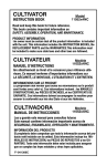
8
CT16
1.1996
Spare Parts
Piéces Dètachées
Owner's Manual 601 00 18-54
Reference No. 337411 05/03/95
SAFETY RULES
THESE SAFETY RULES ARE FOR YOUR PROTECTION. READ THEM CAREFULLY
IMPORTANT
SAFETY STANDARDS REQUIRE OPERATOR PRESENCE CONTROLS TO MINIMIZE THE RISK OF INJURY. YOUR TILLER/
CULTIVATOR IS EQUIPPED WITH SUCH CONTROLS. DO NOT ATTEMPT TO DEFEAT THE FUNCTION OF THE OPERATOR
PRESENCE CONTROL UNDER ANY CIRCUMSTANCES.
BEFORE USE
●
Never allow bystanders near the tiller/cultivator.
●
●
Keep children and pets away while operating.
●
Never operate the tiller/cultivator without good
visibility or light.
●
Do not run the engine indoors. The exhaust fumes
are dangerous (containing CARBON MONOXIDE, an
ODORLESS and DEADLY GAS).
●
Take all possible precautions when leaving the
tiller/cultivator unattended. Stop the engine.
●
Do not overload the tiller/cultivator capacity by
attempting to till too deep at too fast a rate.
Read the owner’s manual carefully. Be thoroughly familiar with the controls and the proper
use of the tiller/cultivator. Know how to stop
the tiller/cultivator and disengage the controls quickly.
●
Do not operate the tiller/cultivator without
wearing adequate outer garments. Wear footwear
that will improve footing on slippery surfaces.
●
Keep the area of operation clear of all persons, particularly small children and pets.
●
Thoroughly inspect the area where the tiller/ cultivator
is to be used and remove all foreign objects.
SAFE STORAGE
FUEL SAFETY
●
Handle fuel with care; it is highly flammable.
●
Use an approved container.
●
Check fuel supply before each use, allowing space for
expansion as the heat of the engine and/or sun can
cause fuel to expand.
●
Fill fuel tank outdoors with extreme care. Never fill fuel
tank indoors. Replace fuel tank cap securely and
wipe up spilled fuel.
●
Never remove the fuel tank cap or add fuel to a
running or hot engine.
●
Never store fuel or tiller/cultivator with fuel in
the tank inside a building where fumes may reach an
open flame.
●
Always refer to the owner's manual instructions
for important details if the tiller/cultivator is to be
stored for an extended period.
●
Never store the tiller/cultivator with fuel in the
fuel tank inside a building where ignition sources
are present such as water and space heaters,
clothes dryers, and the like. Allow the engine to
cool before storing in any enclosure.
●
Keep the tiller/cultivator in safe working condition.
Check all fasteners at frequent intervals for proper
tightness.
FUEL SAFETY
●
After striking a foreign object, stop the engine
(motor). Remove the wire from the spark plug,
and keep the wire away from the plug to prevent
accidental starting. Thoroughly inspect the
tiller/cultivator for any damage, and repair the
damage before restarting and operating the
tiller/cultivator.
●
If the tiller/cultivator should start to vibrate
abnormally, stop the engine (motor) and
check immediately for the cause. Vibration is
generally a warning of trouble.
●
Stop the engine (motor ) whenever you leave
the operating position. Also, disconnect the
spark plug wire before unclogging the tines
and when making any repairs, adjustments, or
inspections.
●
When cleaning, repairing, or inspecting, shutoff the engine and make certain all moving
parts have stopped.
●
Never attempt to make any adjustments while
the engine is running (except when specifically
recommended by the manufacturer).
OPERATING SAFETY
●
Never allow children or young teenagers to
operate the tiller/cultivator. Keep them away
while it is operating. Never allow adults to
operate the tiller/cultivator without proper instruction.
●
Always wear safety glasses or eye shields during
operation or while performing an adjustment or repair to
protect your eyes from foreign objects that may be
thrown from the tiller/cultivator.
●
Do not put hands or feet near or under rotating
parts.
●
Exercise extreme caution when operating on
or crossing gravel drives, walks, or roads. Stay
alert for hidden hazards or traffic.
●
Exercise caution to avoid slipping or falling.
●
Never operate the tiller/cultivator without proper
guards, plates, or other safety protective devices in place.
●
Never operate the tiller/cultivator at high transport
speeds on slippery surfaces. Look behind and use
care when backing.
LOOK FOR THIS SYMBOL TO POINT OUT IMPORTANT SAFETY PRECAUTIONS. IT MEANS
ATTENTION!!! BECOME ALERT!!! YOUR SAFETY IS INVOLVED.
2
OWNER'S INFORMATION
Record the following information about your unit so that you will be able to provide it in case of loss or theft.
MODEL NUMBER:
PURCHASE DATE:
(Enter complete 8 digit number from model plate on unit)
/
/
SERIAL NO.:
CODE NO.:
DEALER'S NAME AND ADDRESS:
CITY:
STATE:
TELEPHONE:
WARNING : This unit is equipped with an internal combustion engine and should not be used on or near any unimproved forestcovered, brush-covered or grass-covered land unless the engine's exhaust system is equipped with a spark arrester meeting
applicable local or state laws (if any). If a spark arrester is used, it should be maintained in effective working order by the operator.
In the State of California the above is required by law (Section 4442 of the California Public Resources Code). Other states may
have similar laws. Federal laws apply on federal lands. A spark arrester for the muffler is available through your nearest engine
authorized service dealer.
TABLE OF CONTENTS
SAFETY RULES ...................................................2
TABLE OF CONTENTS ...................................... 3
OWNER'S INFORMATION .................................. 3
CONTENTS OF PARTS BAG .............................. 3
ASSEMBLY ....................................................... 4-5
OPERATION ..................................................... 6-9
MAINTENANCE ............................................ 10-11
SERVICE AND ADJUSTMENTS ................... 12-13
STORAGE ........................................................... 14
TROUBLESHOOTING ....................................... 15
REPAIR PARTS ............................................ 16-21
WARRANTY ......................................... Back Cover
PARTS
CONTENTS OF SHIPPING CARTON
TO REMOVE TILLER/CULTIVATOR
FROM CARTON
1 - 10 inch Tiller/Cultivator completely assembled
except for the handles and throttle control assembly
1 - Upper Handle
1 - Left Hand Lower Handle
1 - Right Hand Lower Handle
1 - Owner's Manual (Not Shown)
1 - Bag of Assembly Parts (See below)
TOOLS REQUIRED FOR ASSEMBLY
2 - 7/16 inch Wrenches (or adjustable wrenches)
1 - Regular Screwdriver
1 - Pair Scissors
●
Remove plastic parts bag for tiller/cultivator from
carton.
●
Remove handles from the carton.
●
Remove remainder of packing material from carton.
●
Lift the tiller/cultivator out of carton and place on
a hard, level surface.
●
Remove packing material from around tines.
PARTS BAG
CONTENTS OF PARTS BAG (shown actual size)
1 - 10-16 x 1-1/2 Inch
Washer Head Tap Screw
1 - Tie Strap
1 - Shut-Off Switch and Parts
California Proposition 65 WARNING!
The engine exhaust from this product contains chemicals known to the State of
California to cause cancer, birth defects or other reproductive harm.
3
ASSEMBLY
FIG. 1-ASSY
CAUTION: ALWAYS WEAR SAFETY
GLASSES OR EYE SHIELDS WHILE ASSEMBLING TILLER/CULTIVATOR.
2 SPACERS
2 SPACERS
2 HANDLE
MOUNTING
SCREWS
2 LOCKNUTS
FIG. 1-OP on page 6 shows the tiller/cultivator completely
assembled.
Reference to the right and left hand side of the
tiller/cultivator is from the operator's position behind the unit.
TINE
SHIELD
TO INSTALL THE HANDLE ASSEMBLY
The lower handles have a short bend at the bottom end and are
flattened at the top to allow the upper handle to be placed
between the lower handles. To assemble the handles, do the
following:
●
Unwind the throttle control from around the engine and
straighten the cable. Be careful you do not kink the cable.
●
Remove two locknuts, four spacers and two handle
mounting screws from the tine shield (See FIG. 1ASSY).
●
Insert the right side lower handle section into the
mounting channel between the tine shield and the
engine casting (See FIG. 2-ASSY). Push the mounting
screws through the tine shield , handle and approxi
mately halfway into the engine casting. Be sure a spacer
is on each mounting screw (See FIG. 3-ASSY). It may
be necesary to rotate the lower handle to align the
mounting holes. To allow proper mounting of the upper
handle section be sure the flat portion of the lower handle
is facing inward.
●
FRONT VIEW
FIG. 2-ASSY
TINE
SHIELD
LOWER END
OF HANDLE
Position the left side lower handle section into the
mounting channel between the tine shield and the
engine casting. Align the holes in the handle with the
engine casting and the tine shield, then push the
mounting screws completely through the engine
casting, tine shield and handle. Install a spacer onto
the mounting screws and secure the lower
handle sections using two locknuts previously
removed (See FIG . 3-ASSY). Finger tighten the
locknuts at this time.
●
Remove hardware from upper handle.
●
Place the upper handle between the lower handles (See
FIG. 4-ASSY) and secure with two curved head carriage
bolts, two formed washers, two 11/32 inch flatwashers
and two tee knobs (removed earlier) on the inside of the
handle. You must insert a hex nut into each tee knob.
Finger tighten only. Pull back on the tee knob to engage
the hex opening with the hex nut. Tighten the tee knob.
The nut will be pulled into the cavity and locked. The lower
handles have two holes at the top end to allow the upper
handle to be positioned at two different heights.
●
FIGURE 3
MOUNTING
CHANNEL
Figure 4
FIG. 3-ASSY
SPACERS
LOCKNUTS
SPACERS
Using two 7/16 inch wrenches, tighten the locknuts on the
screws in the lower ends of the lower handles just enough
to hold the lower handles firmly in place.
MOUNTING
Figure
5
SCREWS
4
TINE SHIELD
ASSEMBLY
IMPORTANT: OVERTIGHTENING THE SCREWS
ENOUGH TO CHANGE THE SHAPE
OF THE HANDLES CAN RESULT IN
DAMAGE TO THE ENGINE CASTING.
●
NO. 10 X 1-1/2 INCH
HEX HEAD SCREW
HANDLE
GRIP
UPPER
HANDLE
Hold the curved head carriage bolt against theoutside of
the lower handle while tightening the tee knobs securely.
TEE
KNOB
TO INSTALL THE THROTTLE CONTROL ASSEMBLY
●
●
●
FIG. 4-ASSY
HANDLE
GRIP
Place a No. 10 x 1-1/2 inch hex head screw down
through the hole in the upper handle right side and
attach the throttle control to the underside of the
handle (See FIG. 4-ASSY).
THROTTLE
CONTROL
Attach the throttle cable to the right lower handle by
threading a tie strap through the hole in the lower
handle and around the throttle cable on the outside
of the handle (See FIG. 4-ASSY).
CURVED HEAD
CARRIAGE
BOLT
11/32 INCH
FLATWASHER
TIE STRAP
●
Cut off excess strap.
RIGHT LOWER
HANDLE
FIG. 5-ASSY
NOTE: One side of the tie strap is rough, while the other side
is smooth. The rough side must be on the inside of the loop
formed when the ends of the tie strap are put together.
Try to loosen the tie strap. If it will loosen, it is put
together with the smooth side to the inside of the
loop. Remove the tie strap and reverse the direction.
LEFT LOWER
HANDLE
FORMED
WASHER
Thread the pointed end of the strap through the
other (square) end of the strap and pull tight around
the throttle cable and lower handle.
●
HEX
NUT
TO INSTALL THE REMOTE SHUT-OFF
SWITCH
●
Assemble shut off switch (See FIG. 5-ASSY).
●
Attach assembled switch to left lower handle (switch on
inside of handle) with a No. 10x1-1/16 inch hex head
screw and a No. 10 keps nut. Tighten securely.
●
Push switch wire onto prong on bottom side of switch
(See FIG. 5-ASSY).
●
Attach switch wire to left lower handle (See FIG. 6ASSY) as close to the engine casting as possible with a
cable tie
strap.
FIG. 6-ASSY
5
OPERATION
KNOW YOUR TILLER/CULTIVATOR
READ THIS OWNER’S MANUAL AND SAFETY RULES BEFORE OPERATING YOUR TILLER/CULTIVATOR. Compare the
illustrations with your tiller/cultivator to familiarize yourself with the location of various controls and adjustments. Save this manual
for future reference.
FIG. 1-OP
RECOIL STARTER HANDLE
SHUT-OFF SWITCH
UPPER HANDLE
ON
LEFT SIDE
LOWER HANDLE
THROTTLE
CONTROL
OFF
C
H
O
K
FULL
E
OFF
FUEL TANK
AIR CLEANER
CHOKE CONTROL LEVER
CUL/DET ENGINE
RIGHT SIDE
LOWER HANDLE
DEPTH ROD/
TRANSPORT WHEELS
TINE SHIELD
CULTIVATOR TINES
DEPTH ROD/TRANSPORT WHEELS - Used to adjust the
depth of the cut. It also acts as a brake to help the operator
control the direction and speed of the tiller/cultivator. It is
adjusted by removing the hairpin cotter and the clevis pin and
moving the depth rod to a different setting. Turn the depth rod
with the wheels down to transport the tiller/cultivator.
THROTTLE CONTROL - Controls the engine speed
and the tine rotation. This tiller/cultivator is equipped with a
centrifugal clutch that engages the tine drive system when the
engine speed is increased.
CHOKE CONTROL LEVER - Used to assist in starting
a cold engine.
SHUT-OFF SWITCH - Used to stop the engine.
STARTER HANDLE - The engine on this tiller/cultivator is
equipped with an easy pull recoil starter.
7
OPERATION
The operation of this tiller/cultivator can result in foreign objects being thrown into the eyes,
which can result in severe eye damage. Always wear safety glasses or eye shields while
operating the tiller/cultivator.
We recommend standard safety glasses or Wide Vision Safety Mask for over your glasses.
CAUTION: GASOLINE IS FLAMMABLE
AND CAUTION MUST BE USED WHEN
HANDLING OR STORING IT. DO NOT
FILL FUEL TANK WHILE TILLER/CULTIVATOR IS RUNNING, HOT, OR WHEN
TILLER/CULTIVATOR IS IN AN ENCLOSED AREA. KEEP AWAY FROM OPEN FLAME,
ELECTRICAL SPARK, AND DO NOT SMOKE WHILE
MIXING FUEL OR FILLING THE FUEL TANK. NEVER
FILL FUEL TANK COMPLETELY; BUT FILL THE TANK
TO WITHIN 1/2 INCH FROM THE TOP TO PROVIDE
SPACE FOR EXPANSION OF FUEL. ALWAYS FILL
FUEL TANK OUTDOORS AND USE A FUNNEL OR
SPOUT TO PREVENT SPILLING. MAKE SURE TO
WIPE UP ANY SPILLED FUEL BEFORE STARTING
ENGINE.
CAUTION: KEEP AWAY FROM THE
ROTATING PARTS. ROTATING PARTS CAN
CAUSE INJURY.
TO STOP TILLER/CULTIVATOR
●
Release the throttle control to stop the tines.
●
Move the shut-off switch on the engine to the
"OFF" position.
TO OPERATE CULTIVATOR
●
Set the depth rod to the desired tilling position as
follows:
STORE GASOLINE IN A CLEAN, APPROVED CONTAINER, AND KEEP THE CAP IN PLACE ON THE
CONTAINER. KEEP GASOLINE IN A COOL, WELL
VENTILATED PLACE; NEVER IN THE HOUSE. NEVER
BUY MORE THAN A 30 DAY SUPPLY OF GASOLINE
TO ASSURE VOLATILITY. GASOLINE IS INTENDED
TO BE USED AS A FUEL FOR INTERNAL COMBUSTION ENGINES; THEREFORE, DO NOT USE GASOLINE FOR ANY OTHER PURPOSE. SINCE MANY CHILDREN LIKE THE SMELL OF GASOLINE, KEEP IT OUT
OF THEIR REACH BECAUSE THE FUMES ARE DANGEROUS TO INHALE, AS WELL AS BEING EXPLOSIVE.
Remove the hairpin cotter from the clevis pin
securing the depth rod (See FIG. 1-OP). Remove
the clevis pin and adjust the depth rod upward to
dig shallower or downward to dig deeper. Reinstall
the clevis pin and hairpin cotter.
●
With engine running, tilt the unit back on the depth bar
until the tines are off the ground and squeeze the throttle
control all the way up against the hand grip. The engine
is governor controlled and should be run at full throttle.
●
Grasp the handles firmly and slowly tilt the unit
forward to begin the tilling action.
●
As the tines begin to make contact with the ground,
hold back on the handles so that the tines will dig
and not ride forward over the ground. Hold back until
the tines dig into the soil.
●
If the tilled depth is too deep or too shallow, turn off
the engine and reset the depth rod.
●
If depth rod is not controlling forward action,
lower the depth rod. If the unit is not going forward, raise
the depth rod.
WARNING: Experience indicates that alcohol blended fuels
(called gasohol or using ethanol or methanol) can attract
moisture which leads to separation and formation of acids
during storage. Acidic gas can damage the fuel system of an
engine while in storage. To avoid engine problems, the fuel
system should be emptied before storage for 30 days or
longer. Drain the gas tank, start the engine and let it run until
the fuel lines and carburetor are empty. Use fresh fuel next
season. See Storage Instructions for additional information.
Never use engine or carburetor cleaner products in the fuel
tank or permanent damage may occur.
BEFORE STARTING ENGINE
FILL GAS
The two cycle engine used on this tiller/cultivator requires a
mixture of gasoline and oil for lubrication of the bearings and
other moving parts. The correct fuel mixture ratio is 24:1 (See
Fuel Mixture Chart). Gasoline and oil must be pre-mixed in a
clean gasoline container. Always use fresh, clean unleaded
gasoline.
8
OPERATION
CAUTION: DO NOT TOUCH THE THROTTLE
CONTROL WHILE STARTING THE ENGINE.
THE TILLER/CULTIVATOR WILL PROPEL ITSELF IF THE ENGINE SPEED IS ADVANCED
FROM IDLE.
GASOLINE AND OIL MIXTURE
Mix gasoline and oil as follows:
●
Pour 1 U.S. quart of fresh, clean, unleaded automotive gasoline into a gallon gasoline container.
●
Add (5 oz.) of clean, high quality two-cycle oil into
the gasoline container.
IMPORTANT: DO NOT USE OUTBOARD MOTOR
OIL OR MULTI-VISCOSITY OILS,
SUCH AS 10W-30 OR 10W-40.
DISREGARD MIX RATIO INFORMATION ON OIL CONTAINTER IF
INSTRUCTIONS CONFLICT WITH
FUEL MIXTURE CHART BELOW.
●
●
Reinstall the cap on the gasoline container and
shake container vigorously so the oil mixes with the
gasoline.
Add an additional 3 U.S. quarts of gasoline to the
gallon container and shake the container again.
FUEL MIXTURE CHART (Mixture 24:1)
U. S.
GAS OIL
1 Gal.
5 oz.
2 Gal. 11 oz.
5 Gal. 27 oz.
●
●
Tilt the tiller/cultivator back on the depth
rod or transport wheels to raise the tines off the
ground.
●
Grasp the upper handle firmly to stabilize the
tiller/cultivator and pull the starter handle
with short quick pulls. Do not allow the starter
handle to snap back, let it rewind slowly while
holding the starter rope. It will take a few pulls on
the starter handle to feed gas from the fuel tank
to the carburetor.
●
When engine starts, move the choke control to 1/2
choke position until the engine runs smoothly.
Then move choke control to (OFF) position.
●
If engine falters, move choke control to 1/2 choke
position until engine runs smoothly. Then move
choke control to (OFF) position.
●
If engine fires, but does not continue to run, move
choke control to no choke position and repeat
starting instructions.
S. I. (METRIC)
NOTE: If the tines do not stop when the throttle control is
released, adjust the carburetor idle speed as instructed in
Step 5 of Carburetor Adjustment paragraph in the Service/
Adjustments section of this manual.
GAS
OIL
4 Liters .167 L
8 Liters .333 L
20 Liters .833 L
This completes the special gasoline mixing (24:1)
procedure. It can now be poured into the tiller/
cultivator fuel tank.
IMPORTANT: DO NOT FILL FUEL TANK WITH
GASOLINE THAT DOES NOT HAVE
OIL MIXED IN IT. DO NOT USE GASO
LINE ADDITIVES BECAUSE THE ENGINE MAY BE DAMAGED. SHAKE
THE GASOLINE CONTAINER BEFORE EACH FILLING OF THE FUEL
TANK.
Before starting the engine, be sure you have read and understood all the instructions on the preceding pages.
Fill the fuel tank (to 1/2 inch below the bottom
of the fill neck) with fresh fuel mix and reinstall the
fuel tank cap securely. Never use fuel that may be
stale from long periods of storage.
●
Move the shut-off switch to the (ON) position.
●
Move the choke control (see FIG. 1-OP) to the (FULL)
choke position (all the way down).
To stop the engine, release the throttle control and
move the shut-off switch to the (OFF) position.
●
If the engine becomes flooded, see the Spark Plug
Maintenance paragraph in the Maintenance section of this manual. Then pull the starter rope with
the choke control in the (OFF) position.
CAUTION: THE MUFFLER AND SURROUNDING AREAS BECOME HOT AFTER RUNNING
THE ENGINE. AVOID THESE AREAS.
TO START THE ENGINE
●
●
NOTE: A warm engine should not require choking.
9
OPERATION
TILLING HINTS
●
Tilling is digging in, turning over and breaking up packed
soil before planting. Loose unpacked soil helps root
growth. Best tilling depth is 4 to 6 inches. Tilling will also
clear the soil of unwanted vegetation. The decomposi
tion of this vegetation matter enriches the soil. De
pending on the climate (rainfall and wind), it may be
advisable to till the soil at the end of the growing season
to further condition the soil.
●
Avoid tilling the soil that is too dry as the soil pulverizes
and produces a dust that will not hold water. Also, tilling
soil that is too wet will produce unsatisfactory clods
besides being hard on the machine.
●
Better growth will be obtained in tilled ground if a rela
tively small area is tilled properly and the tilled ground
used soon after tilling to preserve the moisture content.
●
●
●
FIG. 2-OP
CLEVIS PIN
DEPTH ROD
FIGURE 7
The depth rod (on the back of the tiller/cultivator)
serves a dual purpose (See FIG. 2-OP). It helps regulate
thedepth of the cut to a uniform level and also acts as a
brake to help the operator control the speed of the
tiller/cultivator. Also, with the wheels down, it is used
for transporting the unit.
●
DEPTH ROD IN TILLING POSITION
CAUTION:
Lowering the depth rod will slow the tiller/cultivator and
make it till deeper. Raising the depth rod will allow the
tiller/cultivator to move faster and till more shallow.
• READ THE OPERATOR'S MANUAL.
If the tiller/cultivator stops forward motionand tries to dig
deeper than necessary, move the handles from side to
side to start forward motion.
• KEEP ALL SAFETY DEVICES AND SHIELDS
IN PLACE.
• KNOW LOCATION AND FUNCTIONS OF ALL
CONTROLS.
• NEVER ALLOW CHILDREN OR UNINSTRUCTED ADULTS TO OPERATE TILLER.
CULTIVATING HINTS
●
HAIRPIN
• SHUT OFF ENGINE BEFORE UNCLOGGING
TINES OR MAKING REPAIRS.
When cultivating (weed killing) it is best to till no deeper
than 1-1/2 inches. Tilling deeper will only pull to the
surface ungerminated weed seeds.You may want to
raise the depth rod to lessen the braking action.
• KEEP BYSTANDERS AWAY FROM MACHINE.
• KEEP AWAY FROM ROTATING PARTS.
When cultivating around plants or close areas you may
want to remove the outside tines (See Tine Replace
ment paragraph in the Service/Adjustments
section of this manual).
WARNING:
• KEEP AWAY FROM ROTATING TINES.
• ROTATING TINES CAN CAUSE INJURY.
10
MAINTENANCE
GENERAL
ing Service Recommendations Chart is provided to assist
the operator properly maintain the tiller/cultivator.
The warranty on this tiller/cultivator does not cover items that
have been subjected to operator abuse or negligence. To
receive full value from the warranty, the operator must maintain the tiller/cultivator as instructed in this manual. The follow
SERVICE RECOMMENDATIONS CHART
SERVICE RECORDS
Fill in dates as you
complete regular service
SCHEDULE
Before
Each
Use
After
first 2
Hours
Every
25
Hours
Every
75
Hours
SERVICE DATES
Before Before
Storage Each
Season
Tighten All Screws and Nuts
Lubricate Transmission
Lubricate Tine Shaft
Clean and Re-Oil Air Cleaner Filter
Check Spark Plug
Cylinder Exhaust Ports
Drain Fuel
FIG. 1-C.R.
LUBRICATION
AIR VENT
SCREW
Every 25 hours and/or at the beginning of each season, the
gear box should be filled with lubricant. Tubes of gear lubricant
are available from most automotive supply stores. Use portable tool grease such as Lubriplate 630AA (Product No.
06787 - 1-3/4 oz. tube) or Lubriplate GR-132 (Product No.
15892 - 10 oz. tube). The tine shaft should have oil applied
before storage and after cleaning if the tiller/cultivator is
flushed with water. The following illustration is provided to
assist the operator properly maintain the tiller/cultivator.
FELT
WASHER
GREASE
FITTING
(Lubricate the
gear box with
Lubriplate
630AA or
Lubriplate GR132)
CHECK TRANSMISSION GREASE LEVEL
●
Remove both left side tines (See Service and Adjust ments section) in this manual.
●
Remove the air vent screw (See FIG. 1-C.R.) from the top
left side of the transmission.
●
Using a grease gun, fill the transmission through the
grease fitting until the new grease begins to come out of
the air vent screw hole.
●
Reinstall the air vent screw.
●
Check the condition of the felt washer in the side of the
transmission at the tine shaft (See FIG. 1-C.R.). Re
place the felt washer if it is damaged (See Repair Parts
section in this manual).
●
Clean tine shaft, spread a few drops of oil on shaft in tine
replacement areas. Reinstall the tines.
●
Remove the right side tines. Check the felt washer for
damage, clean and oil the tine shaft. Reinstall the tines.
TRANSMISSION
TINE SHAFT
(Oil the tine shaft before storage
and after cleaning if the
dethatcher/ cultivator is flushed
with water)
VIEW OF LEFT SIDE WITH TINES REMOVED
11
MAINTENANCE
ENGINE
AIR CLEANER
FIG. 2-C.R.
The air cleaner filter should be cleaned and reoiled after 3
months or 25 hours of operation. Clean more often under dusty
conditions.
FOAM
ELEMENT
SCREWS
IMPORTANT:
The engine can be worn out in a very
short period of time if dirt or grit is allowed to
enter the engine.
ON
OFF
To clean the air filter, do the following:
C
H
O
K
FULL
E
OFF
●
●
●
Loosen screws on air cleaner cover (See FIG. 2-C.R.)
and remove the cover.
Remove foam element from air cleaner.
Wipe inside of the air cleaner housing clean.
●
Clean the foam element by washing in a strong solution
of water and household detergent. Then rinse thor
oughly in clean water.
●
Wrap foam element in clean cloth and squeeze out
(do not twist) all the liquid until dry.
●
Cover the ends and side of the foam element with same
oil used in fuel mixture. Knead the foam element be
tween fingers to distribute oil and remove excess oil.
●
●
Reinstall foam element in air cleaner housing.
Service the foam element carefully, inspecting for deterio
ration or damage. A defective, improperly serviced, or
misassembled air filter will allow dirt particles to enter the
engine.
●
Reassemble the filter (See FIG. 2-C.R.). Place the cover
on the air cleaner housing and tighten screws to secure
cover to the housing.
COVER
HOUSING
CLEANING (See FIG. 3-C.R.)
Always remove the dirt and debris from the tiller/clutivator after
each use. Remove any string, wire or vegetation that may
become lodged in the mechanism and stop the tine rotation.
Proceed as follows:
CAUTION: NEVER RUN THE ENGINE WITHOUT THE AIR CLEANER ELEMENT INSTALLED. A DEFECTIVE AIR CLEANER CAN
RESULT IN LOSS OF ENGINE POWER AND
CAN CAUSE EXCESSIVE WEAR OR DAMAGE
TO THE ENGINE COMPONENTS IF DIRT OR
DUST IS PERMITTED TO ENTER THE ENGINE
THROUGH THE CARBURETOR. AN AIR
CLEANER THAT IS CLOGGED WITH DUST OR
DIRT SHOULD BE CLEANED AND RE-OILED.
●
Release the throttle control and move the shut-off switch
to the (OFF) position, then disconnect the spark plug
wire.
●
Remove hairpin and clevis pin securing tine(s) assembly
to the shaft and remove the tine(s).
●
Remove lodged material. Reassemble tine(s) on shaft
and secure with a clevis pin and hairpin.
●
Reconnect spark plug wire and restart engine.
FIG. 3-C.R.
TINE SHIELD
CLEVIS PINS
LODGED ITEM
CLEVIS PINS
SPARK PLUG
If the engine is flooded, clean the area around the spark plug
base to prevent foreign material from entering the cylinder(s)
when the plug is removed. Remove and dry the spark plug.
Regap the electrodes to .030 if necessary. If a new spark plug
is needed, refer to the Engine Operation and Maintenance
manual for the proper replacement spark plug. Tighten the
spark plug firmly. If a torque wrench is available, torque the
spark plug to 15 foot-pounds.
LEFT
SIDE
TINES
RIGHT
SIDE
TINES
HAIRPINS
CYLINDER EXHAUST PORTS
The cylinder exhaust ports should be cleaned after each
seventy-five (75) to one hundred (100) hours of operation. For
this procedure we recommend that you take your unit to a
technician trained to work on two cycle engines.
12
HAIRPINS
TRANSMISSION
SERVICE & ADJUSTMENTS
TINE REPLACEMENT
FRONT VIEW
The tiller/cultivator is left hand or right hand as viewed from the
operator's position behind the unit.
FIG. 1SERV.& ADJ.
CLEVIS PINS
All four tines on this unit are different and cannot be interchanged. The tines must be properly installed as shown in
figures 1 and 2 or the tiller/cultivator will not function properly.
The outside tines may be removed to reduce the tilling width
to about 6 inches, for working close around plants or in small
areas, if desired. When reinstalling the outside tines see
below.
LEFT
SIDE
TINES
RIGHT
SIDE
TINES
CAUTION: THE TINES ARE SELF-SHARPENING AND WILL BECOME QUITE SHARP
FROM USE. HANDLE CAREFULLY.
HAIRPINS
The tines will all wear fairly evenly. If the tines are being
replaced because of wear, we recommend that all four tines be
replaced at the same time. To replace the tines, do the
following:
●
Place the shut-off switch to the (OFF) position and
disconnect the spark plug wire.
●
Remove the hairpins and the clevis pins from the
tines on one side of the unit and remove the tines (See
FIG.. 1-SERV.&ADJ.).
●
Clean the tine shaft and oil the shaft at the tine locations.
●
Place the inside tine on the tine shaft and reinstall the
clevis pin and hairpin.
●
When the tines are properly installed, the letter "R" will be
visible on the outside of the right-hand tine (the letter "L"
on the left-hand tine). The letter should appear opposite
the small hole in the side of the tine.
●
Place the outside tine on the tine shaft and reinstall
the clevis pin and hairpin cotter.
●
The outside tine cutting tips will all bend in toward
the inside tine. The letter "R" on the right side or "L"
on the left side should be visible from the outside of the
unit.
●
Repeat steps on the opposite side of the unit.
●
Check to make sure the tines are installed on correct side
of the unit (See FIG. 2-SERV.&ADJ).
FIG. 2SERV.& ADJ.
PROPERLY INSTALLED RIGHT SIDE TINES
RIGHT SIDE INDICATOR
13
SERVICE & ADJUSTMENTS
FIG. 3SERV&ADJ
CARBURETOR ADJUSTMENT
A dirty air cleaner will cause the engine to run improperly
and/or smoke excessively. Be sure the air cleaner is clean
before adjusting the carburetor. Never make unnecessary
adjustments to the carburetor. The carburetor was set at the
factory to operate efficiently under most applications. However, if adjustments are required, we recommend you contact
a competent repairman. If you feel that you are competent to
make carburetor adjustment proceed as follows:
CAUTION: USE EXTREME CARE WHEN
MAKING ADJUSTMENTS THAT REQUIRE
THE ENGINE TO BE RUNNING. KEEP
HANDS, FEET, HAIR AND LOOSE CLOTHING AWAY FROM ANY MOVING PART.
●
IDLE SPEED
ADJUSTING
SCREW
Turn the mixture adjusting screw (See FIG .3S
E
R
V
.
&
A
D
J
.
)
clockwise to close.
MIXTURE
ADJUSTING
SCREW
CARBURETOR
ENGINE SHOWN WITH AIR CLEANER REMOVED
IMPORTANT: TIGHTEN THE ADJUSTING SCREW WITH
YOUR FINGERS TO PREVENT DAMAGE
TO THE CARBURETOR OR ADJUSTING
SCREW.
●
Turn the mixture adjusting screw counterclockwise
(open)1-3/8 turns.
●
Start the engine and let it warm up approximately 3 to 5
minutes. Do not adjust the carburetor when the engine is
cold.
●
If the engine falters or stops after the choke lever is moved
to the (OFF) position, open the mixture adjusting screw an
additional 1/8 turn counterclockwise.
●
With the engine running, release the throttle control (idle
position) to make the mixture adjustments.
a.
Turn the mixture adjusting screw (See FIG. 3
SERV.&ADJ)slowly clockwise until the engine falters.
Note this location.
b.
Turn the mixture adjusting screw slowly counterclockwise until the engine starts to sputter. Note this location.
c.
Turn the mixture adjusting screw clockwise until it is
halfway between the first position where the engine
faltered and the second position where the engine started
to sputter.
●
The idle speed may need to be adjusted after making the
mixture adjustment. If the tines do not turn when the
engine is running and the throttle control is released, the
idle speed will not need adjusting. If the tines turn when
thethrottlecontrol is released, do the following:
a.
Have someone hold the tiller/cultivator back on the depth
bar with the tines off the ground.
b.
Start the engine.
c.
With the throttle in the released (idle) position, turn the
idle speed adjusting screw counter-clockwise until the
tines stop rotating.
CAUTION: NEVER TAMPER WITH THE ENGINE GOVERNOR WHICH IS FACTORY SET
FOR PROPER ENGINE SPEED. OVERSPEEDING THE ENGINE ABOVE THE FACTORY HIGH SPEED SETTING CAN BE DANGEROUS. IF YOU THINK THE ENGINE GOVERNED HIGH SPEEDS NEEDS ADJUSTING, CONTACT A COMPETENT REPAIRMAN WHICH HAS THE PROPER EQUIPMENT AND EXPERIENCE TO MAKE ANY
NECESSARY ADJUSTMENTS.
14
STORAGE
CAUTION: NEVER STORE ENGINE
WITH FUEL IN TANK INDOORS OR IN
ENCLOSED, POORLY VENTILATED
AREA, WHERE FUEL FUMES MAY
REACH AN OPEN FLAME, SPARK OR
PILOT LIGHT AS ON A FURNACE,
WATER HEATER, CLOTHES DRYER,
ETC.
NOTE: The tiller/cultivator should be immediately prepared for
storage at the end of the season or if the unit will not be used
for 30 days or more.
●
Drain the fuel from the fuel tank into an approved container
outdoors, away from open flame.
●
Start and run the engine until it stops due to lack of fuel.
●
Pull the starter handle slowly until you feel resistance due
to compression pressure, then stop.
●
Release the starter tension slowly to prevent the engine
from reversing due to compression pressure. This position
will close both the intake and exhaust ports to prevent
corrosion of the piston and cylinder bore.
OTHER
●
If possible, store your tiller/cultivator indoors and cover it
to give protection from dust and dirt.
●
Cover the tiller/cultivator with a suitable protective cover
that does not retain moisture. Do not use plastic.
TILLER/CULTIVATOR
●
Thoroughly clean the tiller/cultivator. Remove all dirt and
debris from the engine and unit.
●
Remove the tines and oil the tine shaft and reinstall the
tines (See Service/Adjustments section in thismanual).
●
Loosen the tee knobs that secure the upper handle to the
lower handle.
●
Carefully fold the upper handle down making sure the
throttle is not kinked. Tighten the tee knobs.
●
The cross piece of the upper handle (between the lower
handles) can now be used as a carry handle or can be
hooked over a wall hook to store the tiller/cultivator up off
the floor out of the way.
IMPORTANT: NEVER COVER THE TILLER/
CULTIVATOR WHILE THE ENGINE
AND EXHAUST AREAS ARE STILL
WARM.
NOTE: A yearly checkup or tuneup by a competent repairman
is a good way to insure that your tiller/cultivator will provide
maximum performance for the next season.
ENGINE
IMPORTANT: IT IS IMPORTANT TO PREVENT GUM
DEPOSITS FROM FORMING IN ESSENTIAL FUEL SYSTEM PARTS
SUCH AS THE CARBURETOR, FUEL
FILTER, FUEL HOSE OR TANK DURING STORAGE. ALSO, EXPERIENCE
INDICATE THAT ALCOHOL
BLENDED FUELS (CALLED GASOHOL OR USING ETHANOLOR
METHANOL) CAN ATTRACT MOISTURE WHICH LEADS TO SEPARATION AND FORMATION OF ACIDS
DURING STORAGE. ACIDIC GAS
CAN DAMAGE THE FUEL SYSTEM
OF AN ENGINE WHILE IN STORAGE.
15
TROUBLE SHOOTING
TROUBLE
CAUSE
CORRECTION
Difficult starting
Stale fuel mixture
Drain fuel tank. Fill with fresh mixture.
Too much oil in mixture
Check fuel mix chart and mix fresh fuel.
Engine runs erratically
Dirt in fuel tank or out of fuel
Clean fuel tank. Fuel tank should be half full
when starting engine.
Engine will not run at
full speed
Carburetor out of adjustment
See carburetor adjustment section.
Fouled spark plug
Clean and re-gap plug.
Plugged air cleaner
Clean and re-oil air cleaner.
Engine speed does not
increase properly
Debris interferring with throttle linkage
Blow dirt and debris off top of carburetor.
Engine smokes
excessively
Plugged air cleaner
Clean and re-oil air cleaner.
Too much oil in fuel mixture
Check fuel mix chart and mix fresh fuel.
Tines continue to
rotate when throttle
control is released
Carburetor out of adjustment
Adjust carburetor idle speed. See
Carburetor Adjustment paragraph in
Service/Adjustments section of this manual.
Tines will not turn
Foreign object lodged in tine
Remove lodged item. See Cleaning
paragraph in the Maintenance section of
this manual.
Unit does not till
properly
Incorrect tine installation
Check the tines for proper installation. See the
Tine Replacement paragraph in the
Service/Adjustment section of this manual.
16