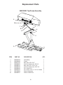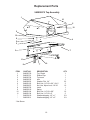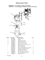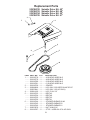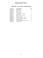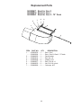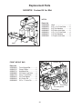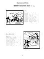
1
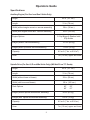
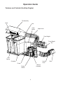
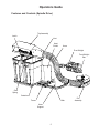
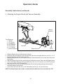
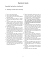
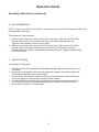
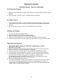
Z2-7 Collection System
Operator’s Manual
Parts Manual
Models: 540200800
Please read these instructions carefully and make
sure you understand them before using the machine.
MANUAL NO. 540200855 REV 3 (04/14/03)
Index
Operators Guide
Specifications ............................................................................................ 3
Features and Controls (Auxiliary Engine) ................................................... 4
Features and Controls (Spindle Drive) ........................................................5
General Information ................................................................................... 6
Safety Procedures ..................................................................................... 6
Unpacking Instructions .............................................................................. 8
Assembly Instructions ............................................................................... 8
Servicing the Engine ............................................................................... 13
Pre-Start Check ....................................................................................... 13
Starting the Engine .................................................................................. 13
Operating the Vacuum............................................................................. 13
Maintenance and Service Instructions
Cleaning and Washing ............................................................................ 14
Storage .................................................................................................... 14
Preventative Maintenance Schedule ........................................................ 14
Engine Service and Maintenance ............................................................ 15
Caring for Vacuum Hoses ....................................................................... 15
Cleaning Exhaust Screen ........................................................................ 15
Trouble Shooting Guide ........................................................................... 16
Replacement Parts
Replacement Parts List ........................................................................... 17
WARNING: Engine exhaust, some of it’s constituents, and certain vehicle components
contain or emit chemicals known to the State of California to cause cancer and birth defects
or other reproductive harm.
©2003 Husqvarna. All rights reserved.
Beatrice, NE. Printed U.S.A.
2
Operators Guide
Specifications
Auxiliary Engine (For Gen I and Gen II Units Only)
Height
42 in. (107 cm.)
Length
31 in. (79 cm.)
Width (without engine mount or vacuum assembly)
39 in. (99 cm.)
Width (with engine mount and vacuum assembly)
63 in. (160 cm.)
Engine Options
5.5 hp Briggs & Stratton Intek
6 hp Kohler
Weight (without vacuum assembly)
107 lb. (49 kg.)
Weight (with 6 hp Kohler vacuum assembly)
172 lb. (78 kg.)
Capacity
8.5 cu ft (7 bu. or 0.24 m3)
Hose
7 in. (18 cm.) upper and lower
Spindle Drive (For Gen II, iZ and Mini Units Only) (Will Not Fit on 72” Decks)
Height
42 in. (107 cm.)
Length
31 in. (79 cm.)
Width (without hose or blower)
39 in. (99 cm.)
Width (with hose and blower)
65 in. (165 cm.)
Deck Options
42”
48”
Weight (without spindle drive/blower assembly)
Weight (with spindle drive/blower assembly)
52”
61”
95 lb. (43 kg.)
155 lb. (70 kg.)
Capacity
8.5 cu ft (7 bu. or 0.24 m3)
Hose
7 in. (18 cm.) upper and lower
3
Operators Guide
Features and Controls (Auxiliary Engine)
Top Assembly
Latch
Inlet
Heat
Shield
Upper Hose
Front Weight
Front Weight
Bar
Gas
Spring
Container
Lower
Hose
Frame
Vacuum
Assembly
Engine
Mount
4
Boot
Operators Guide
Features and Controls (Spindle Drive)
Top Assembly
Latch
Inlet
Heat
Shield
Hose
Front Weight
Front Weight
Bar
Gas
Spring
Container
Frame
Hitch
Hose
Support
5
Fan
Assembly
Operators Guide
General Information
This manual will assist you in the safe operation and proper maintenance of your Husqvarna
equipment. Read it thoroughly before attempting to operate the machine. Call your dealer or
Husqvarna if additional information is required.
The following safety symbols are used throughout the manual to alert you to information about
unsafe actions or situations:
DANGER indicates immediate hazards that may result in severe injury or death
WARNING indicates unsafe actions or situations that may cause severe injury, death and/or major
equipment or property damage.
CAUTION indicates unsafe actions or situations that may cause injury, and/or minor equipment or
property damage.
This equipment should not be modified without the manufacturer’s prior written authorization. Doing
so may not only affect the equipments’ performance and durability, but also create safety hazards for
the operator and the surroundings. Warranty will be void if changes are made to the equipment
without the manufacturer’s prior written authorization.
Safety Procedures
1 - Training:
• Read the Operator’s manual. If the operator(s) or mechanic(s) can not read English it is the
owner’s responsibility to explain this material to them.
• Become familiar with the safe operation of the equipment, operator’s controls, and safety signs.
• All operators and mechanics should be trained. The owner is responsible for training the users.
• Never let children or untrained people operate or service the equipment. Local regulations may
restrict the age of the operator.
• The owner/user can prevent and is responsible for accidents or injuries occurring to themselves,
other people, or property.
2 - Preparation:
• Wear appropriate clothing including hard hat, safety glasses and ear protection. Long hair, loose
clothing or jewelry may get tangled in moving parts.
• Inspect the area where the equipment is to be used and remove all objects such as rocks, toys and
wire which can be thrown by the machine.
• Use extra care when handling gasoline and other fuels. They are flammable and vapors are
explosive. Use only an approved container. Never remove gas cap or add fuel with engine running.
Allow engine to cool before refueling. Do not smoke. Never refuel or drain the machine indoors.
• Check that operator’s controls, safety switches, hoses, and shields are securely attached and
function properly. Do not operate unless they are functioning properly.
6
Operators Guide
3 - Operation
• Never run an engine in an enclosed area.
• Only operate in good light, keeping away from holes and hidden hazards.
• Slow down and use extra care on hillsides. Make turns gradually and at slow speed. Do not
operate across the sides of slopes. Operate up and down slopes only. Do not operate on steep
slopes.
• Turf conditions can affect the machine’s stability. Do not operate on wet grass where traction may
be reduced.
• Do not change the engine governor setting or overspeed the engine.
• Stop equipment and inspect vacuum impellar and hoses after striking objects or if an abnormal
vibration occurs. Make necessary repairs before resuming operations.
• Look behind and down before backing up to be sure of a clear path.
• Slow down and use caution when making turns and crossing roads and sidewalks. Stop vacuum
and mower blades if not mowing.
• Do not operate machine under the influence of alcohol or drugs.
• Use care when loading or unloading the machine into a trailer or truck.
• Use care when approaching blind corners, shrubs, trees. or other objects that may obscure vision.
4 - Maintenance and Storage:
• Stop engine and disconnect spark plug wire. Wait for all movement to stop before adjusting,
cleaning, or repairing.
• Clean grass and debris from muffler and engine to help prevent fires. Clean up oil or fuel spillage.
• Let engine cool before storing and do not store near flame.
• Shut off fuel while storing. Do not store fuel near flames or drain indoors.
• Never allow untrained personnel to service machine.
• Keep hands and feet away from moving parts. If possible, do not make adjustments with the engine
running.
• Keep all parts in good working condition and all hardware tightened. Replace all worn or damaged
decals.
7
Operators Guide
Unpacking Instructions
1.
2.
3.
4.
5.
Wear gloves and eye protection.
Cut straps around carton and remove top.
Take hoses out of carton.
Remove wood pieces. NOTE: Watch for nails and wood splinters.
Slide carton sleeve out of bottom tray and lift over Z2-7
Assembly Instructions
1. Attach hitch to unit (see hitch instructions).
2. Mounting the Z2-7
Hitch
Tools Required:
None
Wire Lock
Pin
Frame
1. Slide the Z2-7 Frame into the Hitch.
2. Line up through holes in the Hitch and Z2-7 Frame and secure with two (2) 3/8” wire lock pins.
8
Operators Guide
Assembly Instructions (continued)
3. Attaching the Heat Shield
Heat
Shield
Tools Required:
1/2” Wrench
1/2” Socket
Ratchet
1. Locate two (2) holes in top corner brace plates of
Hitch.
2. Aligning holes in bottom of Heat Shield, place Heat
Shield onto Hitch.
3. Secure Heat Shield to Hitch using two (2) 5/16”-18
x 1” hex bolts, four (4) 5/16” flat washers, and two
(2) 5/16” nylon lock nuts.
If installing a spindle drive assembly, skip to step 5.
9
Hitch
Operators Guide
Assembly Instructions (continued)
4. Attaching the Engine Mount and Vacuum Assembly
Vacuum
Assembly
Tools Required:
1. Ratchet
2. 1/2” Socket
3. 1/2" Wrench
4. 9/16” Wrench
5. 9/16” Socket
6. 7/16” Socket
7. Socket Extension
Frame
Engine Mount
Inlet
Cover
1. Slide the Engine Mount into the Frame as shown.
2. Place the Vacuum Assembly on the Engine Mount and secure it tightly with four (4) 5/16” x 1-1/2”
hex bolts and four (4) 5/16” nylon lock nuts.
3. Slide the Engine Mount into the Frame so that the Vacuum Assembly is as close to the Frame as
as possible.
4. Adjust the Engine Mount to the nearest aligning holes between the Frame and the Engine Mount.
5. Secure the Engine Mount to the Frame with two (2) 3/8” x 2-1/2” hex bolts, two (2) 3/8” hex nylon
lock nuts, and four (4) 3/8” flat washers.
6. Place the Inlet Cover on the Vacuum Assembly with the inlet cylinder pointing downward and
forward toward the mower deck.
7. Secure the Inlet Cover with six (6) 1/4” flat washers and six (6) 1/4” nylon lock nuts.
NOTE: Auxiliary Engine kits contain a remote throttle cable that is not used with the Z2-7.
10
Operators Guide
Assembly Instructions (continued)
5. Attaching a Spindle Drive Assembly
1. Remove the discharge chute.
2. Remove the right hand belt shield.
3. Remove the deck belt from the right spindle
assembly sheave.
4. Remove this sheave but keep the ¼” square
key and the two washers at hand for reinstallation.
5. Install the Stepped Sheave and spacer/key
retainer included in the kit using the original
key and washers but substituting the original
7/16” HCS with the longer version provided.
An application of anti-seize is recommended.
6. Reinstall the deck belt.
7. The 5/8” hole toward the rear of the ¼” thick
discharge chute mounting bar at the right end
of the deck may be distorted from forming or
loaded with paint. Drill out or fill this hole until
it will accept a 5/8” bolt or piece of bar stock.
Keep the fit close.
8. If any weld beads or the edge of the deck top
project past the right end surface of the deck,
these must be ground back to allow the fan
assembly to fit up flush to the end of the deck.
9. Remove the 3/8” fastener, nut, and clamp from
the inside front corner of the fan assembly.
10. Remove the sheave floor to expose the fan
assembly belt sheave from below.
11. Loosen the nut retaining the belt guide/retainer,
install the belt from the Drive Kit, retighten the
nut, verify the belt clears the guide, and
reinstall the sheave floor.
12. Rest the fan assembly onto the deck end and
slide the pilot thru the 5/8” hole previously
mentioned so that fan assembly is supported
by the pilot and the ¼” stop block welded under
the clamp at the front of the fan assembly.
Note: It may be necessary to swing the
idler pulley away from the assembly
mounting face to clear the chute mounting
bar and the discharge chute mounting tab
on the deck.
13. Reinstall the clamp at the front of the assembly
so that the tab at the lower end of the clamp
passes thru the rectangular slot at the right
front corner of the mower deck, but leave the
fastener loose to ease belt installation.
14. Rotate the belt idler as far forward as possible
and install the belt over the top groove of the
new deck sheave.
15. Tighten the clamp fastener.
16. Using a scribe or other small sharp object,
transfer the mounting hole location at the rear
edge of the fan assembly onto the mating
vertical surface at the right rear of the mower
deck and drill thru with a 25/64” drill.
17. Install the stops on the deck stop pins located
at the rear of the deck then install the new belt
shield.
18. Install the tube support to the main collection
assembly using the 3/8” fastener provided, positioning so that the tube is 2” to 3” away from
the tire.
19. Install the 7” hose to the fan assembly and the
container input port using the hose clamps
provided.
20. Clamp the tube to the tube support.
11
Operators Guide
Assembly Instructions (continued)
6. Hose Attachment
NOTE: Hoses may need to be trimmed to fit. If necessary, see the Hose Trimming section at the end
of the Assembly Instructions.
Tools Required: Flat screwdriver
1. Slide one hose clamp over each end of the 54" Lower Hose. Slide one end of the hose
over the Vacuum Inlet Cover and the other end over the Boot discharge opening.
Tighten the hose clamps to secure hose in place.
2. Slide one hose clamp over each end of the 48" Upper Hose. Slide one end of the hose
over the Vacuum discharge. Slide the other end over the Container Inlet, ensuring
that the red decal on the inlet is completely covered by the hose. Tighten the hose clamps
to secure the hose.
7. Hose Trimming
Tools Required: Utility Knife
1. Carefully measure the length needed. Remember that although the hose is flexible, it will
not stretch.
2. Measure the same length on the hose that needs to be trimmed, and with the utility knife,
cut through the webbing at the proper location.
3 Continue that cut through the webbing all the way around the hose so that it finishes just
across the support coil from where the original cut was started.
4. Use the utility knife to score the support coil between the beginning and end of the web
cut. Set aside the knife, and finish breaking the coil by hand by working the scored
portion back and forth until it breaks apart.
12
Operators Guide
Auxiliary Engine Vacuum Assembly
Servicing the Engine
1. Make sure that engine oil is at engine manufacturer’s recommended level (refer to engine
manual).
2. Fill the fuel tank. Use fresh, clean, unleaded automotive gasoline.
Pre-Start Check
1. Make sure the stop switch is in the OFF position and spark plug wire is disconnected.
Pull the starter rope slowly to make certain there are no foreign objects in the blower
housing.
2. Be sure the spark plug wire and cover are attached to the spark plug.
Starting the Engine
1.
2.
3.
4.
5.
Turn the stop switch to the ON position.
Move the choke lever to the FULL CHOKE position.
Move the throttle lever to the FULL THROTTLE position.
Grasp the starter handle firmly. Pull the handle with a rapid continuous motion.
When the engine starts, move the choke to 1/2 choke and then to NO CHOKE position
Operating the Vacuum
1. NEVER USE THE Z2-7 WITHOUT THE INLET COVER AND ALL HOSES
SECURELY ATTACHED.
2. Make sure both hoses are connected at both ends. Inspect hoses prior to each use.
3. Do not use the Z2-7 on slopes greater than 15 degrees.
4. The mower must be running in order to vacuum debris through the mower deck.
5. In heavy grass it may be necessary to mow and vacuum at a slower ground speed.
6. Never attempt to unclog the Z2-7 until both the mower’s engine and vacuum’s engine
have been shut off and all moving parts have come to a complete stop.
7. Do not stand behind the vent at the rear of the Z2-7 due to the potential for small
pieces of blowing debris to escape through this vent.
8. Be sure to wear eye and ear protection.
9. TO STOP THE ENGINE: throttle down to slow for a few seconds, then push switch to
OFF. Remove any hearing protection and listen for all moving parts to come to a
complete stop. The flywheel in the power head will coast for a few seconds after the
engine is shut off before actually stopping.
13
Maintenance and Service Instructions
Cleaning and Washing
Regular cleaning, washing, and lubricating will prolong the service of the machine.
NOTE: Use care with power washers to avoid damage to decals. Limit direct spray on
these items.
DO NOT EXCEED 1000 PSI WATER PRESSURE FOR CLEANING.
For best results, clean exhaust screen inside container regularly. Instructions for
doing this can be found in the Service section of this manual.
Storage
1.
2.
3.
4.
Refer to engine manufacturer’s instructions for engine storage information.
Clean machine.
Cover all scratches with touch-up paint.
Covered or indoor storage is recommended.
Preventative Maintenance Schedule
Item
Check Engine Oil Level
Before
Each Use
Every
5 Hours
X
Every
25 Hours
Every
50 Hours
X
Change Engine Oil
X
Change Air Cleaner Element
X
Replace Spark Plug
X
Inspect/Clean Exhaust Screen
X
Check/Tighten Nuts & Bolts
X
Check/Tighten Hoses
X
X
Turn Hose End to End
X
Rotate Hose
X
Clean Machine
X
14
Maintenance and Service Instructions
Engine Service and Maintenance
Follow the engine manufacturer’s maintenance instructions. Should any malfunction occur with the
engine during the warranty period, take it to an Authorized Service Dealer. DO NOT tear down the
engine, as this may void the Engine Manufacturer’s Warranty.
NOTE: Refer to engine manufacturer’s owner’s manual for all engine service information.
Caring For Vacuum Hoses
1. Inspect hoses before each use. If hoses have excessive wear, tears, or punctures, replace
immediately.
2. To prolong the life of the hose, periodically rotate hose and turn hose end to end. Refer
to Preventative Maintenance Schedule in this manual.
3. Avoid twists and sharp turns in the hoses, as they will increase wear on the hoses.
4. Avoid dragging the lower hose along the sides of buildings or other hard surfaces.
Cleaning Exhaust Screen
To assist with “blowout” problems that will develop when air cannot exit the containers, the rubber flap
bolted to the upper surface of the steel top insert (right rear corner) is designed to open if the top
assembly is otherwise clogged.
If the rubber flap opens, it will release debris behind the vacuum system. While the containers will
typically continue to fill, this is an indication that the top insert needs to be cleaned.
To clean the top insert:
1. Shut off all engines.
2. While wearing gloves, open the top, remove the containers, and reach in and up to wipe debris off
the expanded metal openings inside the top assembly.
3. A household water hose can also be used to assist in the cleaning process, but the unit should be
allowed to dry as the moisture may cause clogging to occur more quickly during operation.
15
Maintenance and Service Instructions
Trouble Shooting Guide
! DANGER !
Before servicing unit wait for all moving parts to come to a complete stop. Turn engine off and remove
the spark plug wire.
PROBLEM
Engine Does Not Start.
POSSIBLE CAUSE
1. Spark plug wire disconnected.
2. Engine ON/OFF switch in OFF position.
3. Fuel tank empty.
4. Stale gasoline.
5. Dirty air filter.
Engine Runs Poorly.
1. Bad spark plug.
2. Dirty air filter.
3. Incorrect choke setting.
4. Stale gasoline.
CORRECTION
1. Reconnect wire.
2. Put switch in ON position.
3. Add gasoline.
4. Drain gasoline and add fresh
gasoline.
5. Clean or replace.
5. Dirt or water in fuel tank.
1. Inspect spark plug.
2. Clean or replace.
3. Put choke in correct setting.
4. Drain gasoline and add fresh
gasoline.
5. See engine service dealer.
Engine Overheats.
1. Carburetor out of adjustment.
2. Oil level is low.
1. See engine service dealer.
2. Check and add oil.
Loss of Vacuum.
1. Vacuum inlet clogged.
2. Container full.
3. Engine not reaching full RPM.
1. Remove hose and clean inlet.
2. Inspect and empty.
3. See “Engine Runs Poorly”
above.
4. Replace/repair impeller.
4. Fan blades bent or broken.
Unusual vibration
or noise.
1. Solid object jammed in unit.
2. Engine cylinder shaft or crankshaft
bent or damaged.
3. Loose engine mounting bolts/nuts.
4. Loose or missing bolts on unit.
5. Engine shaft bearings damaged.
16
1. Check and remove any
obstruction.
2. See engine service dealer.
3. Tighten bolts/nuts.
4. Tighten or replace bolts.
5. See engine service dealer.
Replacement Parts
540200800 Assembly
1
3
2
4
5
ITEM
1
2
3
4
*
*
5
*
*
*
*
PART NO.
540200853
540093817
540092531
540092767
540200854
540200855
540099693
540093961
540099077
540000413
540099079
DESCRIPTION
Frame/Top Assembly
Container, 30 Gal.
Front Weight
Heat Shield
Small Parts Kit, including:
Manual
Pin, Wire Lock
Ear Plugs
Bolt, Hex, 5/16”-18 x 1”
Washer, Flat, 5/16”
Nut, Hex, Nylon Lock, 5/16”-18
* Not shown
17
QTY.
1
2
3
1
1
1
2
1
2
4
2
Replacement Parts
540200853 Top/Frame Assembly
9
10
3
7
8
4
1
6
5
2
ITEM
PART NO.
1
2
3
4
5
6
7
8
9
10
540092704
540200849
540001765
540099065
540099015
540099079
540099082
540099102
540104804
540200027
DESCRIPTION
Gas Spring
Frame
Bolt, Hex, 3/8”-16 x 3”
Nut, Hex, Nylon Lock, 3/8”-16
Bolt, Hex, 5/16”-18 x 1-1/2”
Nut, Hex, Nylon Lock, 5/16”-18
Pin, Cotter, #13
Pin, Clevis, 5/16” x 1-1/4” w/ 2 holes
Decal, Husqvarna
Decal, Caution List
18
QTY.
1
1
1
1
1
1
2
1
1
1
Replacement Parts
540092675 Top Assembly
1
5
10
5
10
6
5
2
4
3
7
11
8
ITEM
1
2
3
4
5
6
7
8
9
10
11
*
*
PART NO.
540092720
540092761
540092754
540092535
540099074
540000122
540099072
540092702
540093210
540000124
540000134
540093610
540093611
7
9
DESCRIPTION
Top, Plastic
Rubber Flap
Top Insert
Inlet
Washer, Flat, 1/4”
Bolt, Hex, 1/4”-20 x 3/4”, Gd. 5
Nut, Hex, Nylon Lock, 1/4”-20
Latch
Spring
Bolt, Hex, 1/4”-20 x 5/8”
Bolt, Hex, 1/4”-20 x 2”
Weatherstripping, 1/2” x 1”
Weatherstripping, 1/2” x 2”
* Not Shown
19
QTY.
1
1
1
1
22
3
19
1
1
16
2
6 ft
6 ft
Replacement Parts
540030166 6 hp Kohler Vacuum Assembly
540030167 5.5 hp Briggs & Stratton Vacuum Assembly
1
7
4
5
6
4
5
2
3
8
9
ITEM
1
2
3
4
5
6
7
*
*
*
*
*
*
*
8
9
PART NO.
540094004
540107832
540092705
540099001
540099012
540099027
540099002
540094082
540200027
540097081
540097055
540094251
540099015
540099079
540099072
540099074
* Not Shown
DESCRIPTION
QTY.
Blower Housing
1
Impeller
1
Inlet, Blower Housing
1
Washer, Spring, 5/16”
5
Bolt, Hex, 5/16”-24 x 3/4”
5
Screw, Set, 3/8”-24 x 3/8”
2
Key, Square, 3/16” x 3/16” x 1-3/4”1
Decal, Hot Surfaces
1
Decal, Caution List
1
Screw, muffler deflector (Kohler only)
2
Deflector, exhust (Kohler only)
1
Hardware Kit, including:
1
Bolt, Hex, 5/16”-18 x 1-1/2”
4
Nut, Hex, Nylon Lock, 5/16”-18
4
Nut, Hex, Nylon Lock, 1/4”-20
6
Washer, Flat, 1/4”
6
20
Replacement Parts
539106782
539106783
539106784
539106785
Spindle
Spindle
Spindle
Spindle
Drive
Drive
Drive
Drive
Kit,
Kit,
Kit,
Kit,
42”
48”
52”
61”
3
7
1
2
4
5
8
6
ITEM PART NO. QTY
DESCRIPTION
1 ........ 539106778 ..... 1 ........ 42 SHIELD W/DECALS
.......... 539106779 ..... 1 ........ 48 SHIELD W/DECALS
.......... 539106780 ..... 1 ........ 52 SHIELD W/DECALS
.......... 539106781 ..... 1 ........ 61 SHIELD W/DECALS
2 ........ 539106739 ..... 1 ........ SPACER
3 ........ 539990629 ..... 1 ........ HCS 3/8 X 2.25 USED ON 48”/52”/61”
.......... 539976941 ..... 1 ........ HCS 3/8 X 1.25 (42” ONLY)
4 ........ 539991120 ..... 1 ........ HCS 7/16 X 2.5
5 ........ 539106723 ..... 1 ........ BELT-42
.......... 539106724 ..... 1 ........ BELT-48
.......... 539106725 ..... 1 ........ BELT-52
.......... 539106726 ..... 1 ........ BELT-61
6 ........ 539106744 ..... 1 ........ STACKED SHEAVE 42-48
.......... 539106745 ..... 1 ........ STACKED SHEAVE 52
.......... 539106746 ..... 1 ........ STACKED SHEAVE 61
7 ........ 539976979 ..... 1 ........ NUT 3/8 NYLOC
8 ........ 539106787 ..... 2 ........ STOP - USED ON 42” & 48” ONLY
21
Replacement Parts
540200817 Accessories, Auxiliary Engine
PART NO.
540062092
540097154
540097148
540092531
540200717
540097076
540099611
540000415
540099065
540002004
540000403
540001062
540061651
DESCRIPTION
Engine Mount
Hose, 7” x 54”
Hose, 7” x 48”
Front Weight
Small Parts Kit, including:
Hose Clamp
Bolt, Hex, 3/8”-16 x 2-1/2”
Washer, Flat, 3/8”
Nut, Hex, Nylon Lock, 3/8”-16
Nut, Hex, Nylon Lock, #10-24
Washer, Flat, #10
Screw, Slotted Rd Hd, #10-24 x 3/4”
Throttle Cable
22
QTY.
1
1
1
1
1
4
2
4
2
2
2
2
1
Replacement Parts
540200671 Boot for Gen II
540200818 Boot for Gen I
540200941 Boot for Gen II - 72” Deck
5
7
4
6
2
1
3
ITEM
PART NO.
QTY
1 ........ 539200833 ..... 1 ........
.......... 539200664 ..... 1 ........
2 ........ 539080652 ..... 1 ........
3 ........ 539093814 ..... 1 ........
4 ........ 539099046 ..... 4 ........
5 ........ 539099077 ..... 2 ........
6 ........ 539099079 ..... 2 ........
7 ........ 539099082 ..... 1 ........
23
DESCRIPTION
Boot - Gen I
Boot - Gen II & Gen II - 72” deck
Deck bracket
Boot rod, 14"
Washer, 5/16
Bolt, 5/16-18 x 1
Nut, 51/6-18, nylock
Cotter pin, #13
Replacement Parts
540200798 Custom Kit for Mini
HITCH
Parts List
540200809
540099020
540000415
540099065
540099031
540000427
540093082
Hitch ................................... 1
3/8” x 1-1/4” Hex Bolts ........ 2
3/8” Flat Washers ............... 4
3/8” Nylon Lock Nuts ........... 2
1/2” x 1-1/4” Hex Bolts ........ 4
1/2” Flat Washers ............... 8
1/2” Nylon Lock Nuts ........... 4
Hitch
Holddown Bar
FRONT WEIGHT BAR
Parts List
540200810
540092747
540092731
540099065
540001765
540000415
540099616
540099668
Front Weight Bar ............. 1
Clamp Plates .................. 2
Holddown Bar.................. 1
3/8” Nylon Lock Nuts ....... 4
3/8” x 3” Hex Bolts ........... 4
3/8” Flat Washer ............. 8
#11 Cotter Pin ................. 2
3/8” x 1” Clevis Pin .......... 2
Front Weight
Front Weight Bar
Clamp Plate
24
Replacement Parts
540200792 Custom Kit for Gen II
540200927 Custom Kit for Gen II - 72” Deck
HITCH
Parts List
540200749
540099020
540000415
540099065
540099031
540000425
540093082
540099611
540200788
Hitch Spacer
Skid Plates
Hitch Spacer
Hitch
Hitch .................................... 1
3/8” x 1-1/4” Hex Bolts ........ 4
3/8” Flat Washers ............... 8
3/8” Nylon Lock Nuts ...........4
1/2” x 1-1/2” Hex Bolts ........ 4
1/2” Flat Washers ............... 8
1/2” Nylon Lock Nuts ...........4
3/8” x 2-1/2” Hex Bolts ........ 2
Hitch Spacer, Blk Fin. .......... 2
Nuts to Outside
Holddown Bar
FRONT WEIGHT BAR
Parts List
540020255
540200921
540092519
540092731
540099065
540099113
540000415
540099616
540099668
Front Weight Bar .............. 1
Front Weight Bar,
72” deck ............................ 1
Clamp Plates .................... 2
Holddown Bar ................... 1
3/8” Nylon Lock Nuts ......... 4
3/8” x 3-1/2” Hex Bolts ...... 4
3/8” Flat Washer ............... 8
#11 Cotter Pin ................... 2
3/8” x 1” Clevis Pin ............ 2
Front Weight
Front Weight Bar
Clamp Plate
25
Replacement Parts
540200799 Custom Kit for Gen I
HITCH
Parts List
540200828
540099031
540000425
540093082
Hitch ............................... 1
1/2” x 1-1/2” Hex Bolts ... 6
1 /2” Flat Washers ......... 12
1/2” Nylon Lock Nuts ...... 6
Hitch
Locknuts to inside
Holddown Bar
FRONT WEIGHT BAR
Parts List
540020255 Front Weight Bar .................. 1
540092519 Clamp Plates ........................ 2
540092731 Holddown Bar ....................... 1
540099065 3/8” Nylon Lock Nuts ............ 4
540099697 3/8” x 4-1/2” Hex Bolts .......... 4
540000415 3/8” Flat Washer ................... 8
540099616 #11 Cotter Pin ....................... 2
540099668 3/8” x 1” Clevis Pin ............... 2
Front Weight
Front Weight Bar
Clamp Plate
26
Replacement Parts
540200942 Custom Kit for iZ
HITCH
Parts List
540200809
540099020
540000415
540099065
540099031
540000427
540093082
Hitch ....................................
3/8” x 1-1/4” Hex Bolts .........
3/8” Flat Washers ................
3/8” Nylon Lock Nuts ............
1/2” x 1-1/4” Hex Bolts .........
1/2” Flat Washers ................
1/2” Nylon Lock Nuts ............
1
2
4
2
4
8
4
Hitch
Front Weight
Holddown Bar
FRONT WEIGHT BAR
Parts List
540200932
540200934
540092731
540099065
540990591
540000415
540099616
540099668
Front Weight Bar .................. 1
Clamp Plates ........................ 2
Holddown Bar ....................... 1
3/8” Nylon Lock Nuts ............. 4
3/8” x 4-1/2” Hex Bolts .......... 4
3/8” Flat Washer ................... 8
#11 Cotter Pin ....................... 2
3/8” x 1” Clevis Pin................ 2
Front Weight Bar
Clamp Plate
27
Replacement Parts
540200803 Spindle Drive Fan Assembly
19
22
28
21
23
4
7
1
20
6
27
24
39
8
2
23
14
27
38
21
11
10
9
42
40
36
37
35
25
14
18
33
34
31
13
26
44
30
28
29
32
12
45
43
15
41
17
15
16
27
28
46
29
28
29
3
28
Replacement Parts
ITEM
PART NO.
QTY
1 ........ 539106752 ..... 1 ........
2 ........ 539106693 ..... 1 ........
3 ........ 539106706 ..... 1 ........
4 ........ 539106786 ..... 2 ........
6 ........ 539106707 ..... 1 ........
7 ........ 539102691 ..... 5 ........
8 ........ 539990613 ..... 1 ........
9 ........ 539106711 ..... 1 ........
10 ...... 539106713 ..... 1 ........
11 ...... 539990563 ..... 1 ........
12 ...... 539106715 ..... 1 ........
13 ...... 539101836 ..... 1 ........
14 ...... 539990546 ..... 2 ........
15 ...... 539990629 ..... 2 ........
16 ...... 539990655 ..... 1 ........
17 ...... 539990517 ..... 1 ........
18 ...... 539990122 ..... 1 ........
19 ...... 539102535 ..... 1 ........
20 ...... 539100472 ..... 3 ........
21 ...... 539990184 ..... 13 ......
22 ...... 539990717 ..... 3 ........
23 ...... 539990799 ..... 8 ........
24 ...... 539990208 ..... 1 ........
25 ...... 539990362 ..... 2 ........
26 ...... 539106721 ..... 1 ........
27 ...... 539990074 ..... 16 ......
28 ...... 539976978 ..... 16 ......
29 ...... 539990598 ..... 14 ......
30 ...... 539990188 ..... 1 ........
31 ...... 539106801 ..... 1 ........
32 ...... 539106720 ..... 1 ........
33 ...... 539101050 ..... 1 ........
34 ...... 539990037 ..... 1 ........
35 ...... 539100141 ..... 1 ........
36 ...... 539106504 ..... 1 ........
37 ...... 539990247 ..... 1 ........
38 ...... 539106810 ..... 1 ........
39 ...... 539106809 ..... 1 ........
40 ...... 539106811 ..... 1 ........
41 ...... 539106812 ..... 1 ........
42 ...... 539102067 ..... 1 ........
43 ...... 539106751 ..... 1 ........
44 ...... 539106748 ..... 1 ........
45 ...... 539097076 ..... 3 ........
46 ...... 539976979 ..... 1 ........
DESCRIPTION
FAN COVER W/DECALS
UPPER HOUSING
LOWER HOUSING
BEARING WITH COLLAR
FAN WLDMT.
FLANGETTE
NUT, 3/8-16, FLANGE
SHEAVE FLOOR
SHEAVE, 4”
BOLT, 3/8-16 X 1
IDLER ARM
SLEEVE BUSHING
NUT, 3/8-16, CTR. LOCK
BOLT, 3/8-16 X 2 1/4
BOLT, 3/8-16 X 1 1/2
WASHER, 3/8
WASHER, 3/8, SAE
GREASE CAP
BOLT, 5/16-18 X 1 1/4, CARRIAGE
NUT, 5/16-18, CTR. LOCK
NUT, 5/16-18, NYLOC
BOLT, 5/16-18 X 5/8, CARRIAGE
BOLT, 5/16-18 X 1
SCREW, 1/4-20 X 5/8, SELF TAP
IDLER
BOLT, 1/4-20 X 3/4, CARRIAGE
NUT, 1/4-20, NYLOC
WASHER, 1/4
WASHER, 5/16
SPRING ROD
SPRING
VINYL GRIP
COTTER PIN 3/32 X 3/4
BOLT, 7/16-20 X 1 1/2
HEAVY WASHER
LOCKWASHER, 7/16
CLAMP
BEARING PLATE
BELT GUIDE
BACKING
KEY 1/4 X 3/4 SQ.
SUPPORT
HOSE
HOSE CLAMP
NUT, 3/8-16, NYLOC
29