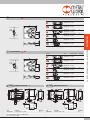
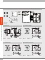
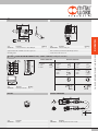
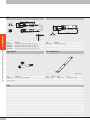
1
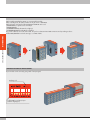
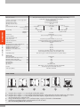
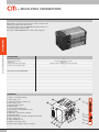
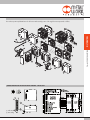
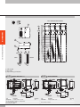
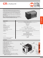
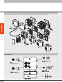
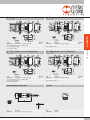
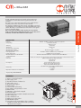
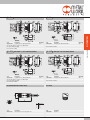
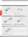
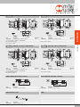
DISTRIBUTORS
FIELDBUS
CM CLEVER MULTIMACH
CLEVER MULTIMACH
THE VALVE IN DETAIL
CM CLEVER MULTIMACH
DISTRIBUTORS
Clever Multimach valves can be used to form autonomous and intelligent
valve island subsystems. Each valve has a microchip that performs
a series of functions connected with operation and dialogue with the
valves before and after it. Valves communicate via serial transmission.
CM refers to the communication protocol patented by Metal Work.
It is a field-bus in its own right, designed specifically for very easy control
of islands of pneumatic solenoid valves. CM valves have a diagnosis
system that detects electrical faults. It can also be used to verify during
installation that all connections are correct.
Multi-pole connections and field buses with different communication
protocols are available for controlling the valve distribution island.
Addressing of single outputs is not required as the connection number
of each solenoid pilot is assigned automatically based on the position
occupied by the valve.
SMART VALVE
Each valve comes with a microchip that controls
operation and dialogue with the other valves.
LOCAL DIAGNOSTICS
Each Clever Multimach valve has a LED
diagnostic system that identifies immediately
whether a pilot is energized, the contact
is interrupted or there is a short-circuit.
LED 14
LED 12
DESCRIPTION OF THE FAUL
OFF OFF No fault, EV1-EV2=OFF
ON (green)OFF
No fault, EV1=ON - EV2=OFF
ON (green)ON (green)
No fault, EV1-EV2=ON
OFFON (green)
No fault, EV1=OFF - EV2=ON
RED (flashing)OFF Solenoid pilot EV1 interrupted or disconnected
OFF
Solenoid pilot EV2 interrupted or disconnected
RED (flashing)
ON (red)OFF
Solenoid pilot EV1 short circuit
OFFON (red)
Solenoid pilot EV2 short circuit
GREEN (flashing)OFF
Data update time out, communication faulty
2
INPUT MODULES
CM CLEVER MULTIMACH
DISTRIBUTORS
With a suitably arranged Clever Center, you can insert add-on modules.
When connecting buses, the add-on modules can only be used for e PNP INPUTs.
With a multi-pole connection, the following INPUTs and OUTPUTs can be used:
• DIGITAL INPUTS, as cylinder sensors for example
• DIGITAL OUTPUTS
• ANALOGUE INPUTS (but the LEDs do not light up)
• ANALOGUE OUTPUTS (but the LEDs do not light up)
They can be combined, even on the same module. You can choose between PNP or NPN connections via a dip switch-type selector.
All the INPUTS/OUTPUTS must be the same type, i.e. all PNP or NPN.
MAXIMUM EXTENSION OF ADD-ON MODULES
Up to 4 modules can be connected, giving a total of 32 input signals.
Ordering code
0227302900
A yellow LED for each input/output
(visible for digital types)
3
EXAMPLE OF A CM LAYOUT
DISTRIBUTORS
The Clever Center can relay command signals to other islands of “slaves”. Transmission, in serial mode, is via a cable with M8 connectors.
Commands can be sent from the first slave island to other slave islands in cascade, again via cables with M8 connectors. Addresses are assigned
automatically, based on intuitive sequential logic. This means that other slaves can be added downstream at any time, until all available outputs are in
use.
Slave 2
Slave 1
CM CLEVER MULTIMACH
M8
Serial
connection
Add-on module 3
Slave 3
Add-on module 4
Clever Center
Add-on module 1
Add-on module 2
Slave 4
NOTES
4
TECHNICAL DATA
Valve port connections
CM CLEVER MULTIMACH
DISTRIBUTORS
Ø 4,6,8 mm automatic fitting for ports 2 and 4 / power supply port for Ø10 automatic fitting /
3/8 thread for exhaust port, M5 thread for exhaust pilot port
Connection on the end-plate 1-11 for the supply of pilots
Automatic fitting Ø 4 mm
Maximum number of pilots
See input end-plate technical data
Maximum number of valves
See input end-plate technical data
Operating temperature range
°C
-10 to +60
Fluid
Filtered air without lubrication; lubrication, if used, must be continuous
Flow rate at 6.3 bar DP 1 bar
Nl/min 11.5 mm Ø 4 11.5 mm Ø 6 14 mm Ø 8
version 5/2 and 3/2 200500650
version 5/3 200300300
Pressure range
X (pilot supply)
1-11 (valve supply)
end-plate 1-11 3 to 7 bar
vacuum at 10 bar
end-plate 1
3 to 7 bar
Voltage range
24 VDC ±10%
(slave protected against overload and reverse polarity)
Power for each pilot
W
0.9
Solenoid Pilot Insulation class
F155
Degree of protection
IP65 (with conveyed exhust, and that - in case of no use)
Diagnostics and protections
Local via PC/PLC fault led. For defects signalled look at the manual.
Outlets protected against overload and short-circuit
Solenoid rating
100% ED
Maximum latency time of the serial transmission
ms
,10
TRA/TRR 2x3/2 monostable at 6 bar
ms
8 / 45
TRA/TRR 5/2 monostable at 6 bar
ms
8 / 33
TRA/TRR 5/2 bistable at 6 bar
ms
20 / 20
TRA/TRR 5/3 cc monostable at 6 bar
ms
20 / 20
Note on use
Insert the pipes in the fittings, before passing air through the valves,
otherwise the gasket may be pulled out of its seat by the flow of air.
Compatibility with oils
Please refer to page 6-7 of the technical documentation see general catalogue
Add-on module
Sensor supply voltage
Maximum current for each single connector
Maximum current for each module
Maximum total current of all the modules
Input impedance
Max input voltage
Type of input
Protection
Active input signalling
mA
mA
mA
KΩ
Vcc
24 VDC ±10%
200
400
1000
3.9
-5 to +30
With field bus: PNP
With multi-pole connection: PNP/NPN configurable via DIP SWITCH
Protected inputs against overload and short-circuit
One LED for each INPUT
FIXING THE BASE
A Fixing from above using the 1 or 1-1 input end-plate and the blind end-plate.
B C Fixing from above using the 1 or 1-1 input end-plate and the blind end-plate, using the M5 threads on the bottom and the rear of the end-plates.
D Fixing from above using the 1 or 1-1 input end-plate and the blind end-plate, using the M5 threads on the front of the end-plates.
An opening for the pipes is made in the plate.
E Fixing on the DIN bar with end-plate 1 or 1-11 and blind end-plate, using the push-in bracket code 0227301600.
F Lateral fixing using the blind end-plate, and its the M4 threads on the side lateral.
Note: The sole fixing admitted is the one showed.
5
KEY TO CODES – CLEVER MULTIMACH
2
VALVE
INPUT END-PLATE
Clever
Multimach
2End-plate
1-11
3 End-plate 1
I/O
FUNCTION
O
multi-pole connection, valves
only
I/O
multi-pole connection,
valves and inputs
ADD
Additional (slave) valves only
PN O
PN I/O
Profinet IO, valves only
Profinet IO, valves and inputs
EC O
EC I/O
EtherCAT, valves only
EtherCAT, valves and inputs
X EN O
X EN I/O
EtherNet, valves only
EtherNet, valves and inputs
CAN O
CAN I/O
M
I6 - W8 - W6 - O4 - L8 - 5
M8 - M8 - 15 - 16
MANUAL TYPE
TYPE OF VALVE
FURTHER DETAILS
M
B
Monostable manual control
Bistable manual control
I
n° 2 3/2 NC
W n° 2 3/2 NO
L
3/2 NO + 3/2 NC
V 5/2 monostable
K 5/2 bistable
O 5/3 monostable
5 Blind end-plate
6Passing-intermede
7 Blind intermediate
20 Exhaust section
4 Cartridge 4
6 Cartridge 6
8 Cartridge 8
● M8 Module 8 input M8
✱ 14 Shell 44 pin
✱ 15 Shell 44 + 44 pin
16 n° 2 brackets for
DIN bar
DISTRIBUTORS
C M
CANopen, valves only
CANopen, valves and inputs
CM CLEVER MULTIMACH
● Not applicable with (add-on) ADD end-plate
✱ For multi-pole connection only
X Not yet suppliable. Contact our sales departments.
NOTES
6
+ MULTI-POLE CONNECTION
CM + MULTI-POLE CONNECTION
DISTRIBUTORS
CM end-plates + multi-pole connection can be used for connection to the
PC/PLC using a 44-pin cable and connector.
The end-plates with provisions for INPUT/OUTPUT add-on modules are
connected using an extra 44-pin cable.
Both valves and INPUTs/OUTPUTs can be PNP or NPN configured.
TECHNICAL DATA
Maximum number of pilots
Maximum number of valves
Voltage range
DC input current without valve modules
Max input current with all valves ON
A
32
32 (same as the max. no. of pilotos)
24VDC ±10%
Nominal Icc 30 mA - Instantaneous Icc (≤25 ms) 650 mA
1.5
Refer to page 5 for general technical data
COMPONENTS
a Exhaust - Solenoid pilot 82/84
b Valve supply - port 1
c Threaded connection of exhausts 3/5
d Valve supply - port 11
e Electrical control supply X
f Blind end-plate
g Screw for valve wall-mounting
h i j Utility port for pipe Ø 4, 6 or 8 mm
k Manual control
l LED (LED on, solenoid valve energised)
m Pneumatic symbol
n Identification of the monostable or bistable manual control
o Valve ordering code
p Valve identification code
q Blank space for valve number
r Clever Center end-plate multi-pole connection
7
m
n
o
p
q
VALVE ISLAND CONFIGURATION
CM + MULTI-POLE CONNECTION
DISTRIBUTORS
The numbers permit rapid identification of the function and assembly position of the single elements represented as follows.
WIRING DIAGRAM FOR THE CLEVER CENTER TERMINAL - VALVES ONLY
a Indicator LED
bGrounding
8
WIRING DIAGRAM FOR THE CLEVER CENTER TERMINAL FOR VALVES AND INPUTS/OUTPUTS
CM + MULTI-POLE CONNECTION
DISTRIBUTORS
INPUT CONNECTION DIAGRAM
MALE
FEMALE
a Indicator LED
bGrounding
c Input selector type PNP/NPN
2-O
OUTPUT END-PLATE 1-11
Code
Description
0227302200
End-plate CM kit 1-11 OUT
This end-plate allows for supplies to be differentiated:
port 2, port 4 and pilot supply
Note: terminator included
9
Weight [g]
722
3-O
OUTPUT END-PLATE 1
Code
0227302201
Description
End-plate CM kit 1 OUT
Note: terminator included
Weight [g]
722
Code
Description
0227302223
End-plate CM kit 1-11 IN/OUT
This end-plate allows for supplies to be differentiated:
port 2, port 4 and pilot supply
Note: terminator included
Weight [g]
722
Description
44-pin cup connector kit IP 65
Weight [g]
722
o 44+44 PIN CUP CONNECTOR KIT IP 65 FOR I/O
Weight [g]
60
CABLES
Code
0226107201
0226107101
0226107102
0226107103
Description
End-plate CM kit 1 IN/OUT
Note: terminator included
n 44-PIN CUP CONNECTOR KIT IP 65
Code
0226180108
Code
0227302225
INPUT/OUTPUT END-PLATE 1
Code
0226180109
Description
44+44 pin cup connector kit IP 65 for I/O
DISTRIBUTORS
3 - I/O
INPUT/OUTPUT END-PLATE 1-11
CM + MULTI-POLE CONNECTION
2 - I/O
Weight [g]
80
IDENTIFICATION PLATE KIT FOR 44-PIN CONNECTOR
Description
10-wire cable
19-wire cable
25-wire cable
44-wire cable
Weight [g/m]
86
122
130
160
Code
0226107000
Description
Identification plate kit
Comes in 10-pc. packs
Specify the number of metres desired
10
CM + MULTI-POLE CONNECTION
DISTRIBUTORS
44-PIN PRE-WIRED CUP CONNECTOR
11
Code
0226950500
44+44-PIN PRE-WIRED CUP CONNECTOR
Description
Connet. IP 65 + cable 44-wire L = 5 m
Weight [g]
740
Code
0226980500
Description
Connet. IP 65 + cable 44 + 44-wire L = 5 m
WIRING DIAGRAM FOR THE 44-PIN CUP CONNECTOR KIT
44 PIN FEMALE PRE-WIRED FOR VALVE
Position of
electrical contact
1
2
3
4
5
6
7
8
9
10
11
12
13
14
15
16
17
18
19
20
21
22
23
24
25
26
27
28
29
30
31
32
33
34
35
36
37
38
39
40
41
42
43
44
Corresponding
wire colour
white
brown
green
yellow
gray
pink
blue
violet
gray + pink ring
red + blue ring
white + green ring
brown + green ring
white + yellow ring
yellow + brown ring
white + gray ring
gray + brown ring
white + pink ring
pink + brown ring
white + blue ring
brown + blue ring
white + red ring
brown + red ring
white + black ring
brown + black ring
gray + green ring
yellow + gray ring
pink + green ring
yellow + pink ring
green + blue ring
yellow + blue ring
green + red ring
yellow + red ring
green + black ring
gray + blue ring
gray + red ring
red + green ring
red + brown ring
red + black ring
yellow + black ring
pink + red ring
pink + blue ring
black + green ring
black + pink ring
black + red ring
44 PIN MALE PRE-WIRED FOR INPUT/OUTPUT
Function
Out 1
Out 2
Out 3
Out 4
Out 5
Out 6
Out 7
Out 8
Out 9
Out 10
Out 11
Out 12
Out 13
Out 14
Out 15
Out 16
Out 17
Out 18
Out 19
Out 20
Out 21
Out 22
Out 23
Out 24
Out 25
Out 26
Out 27
Out 28
Out 29
Out 30
Out 31
Out 32
Fault reporting
NC
NC
+24VDC
+24VDC
+24VDC
Config. PNP/NPN
NC
NC
0 VDC
0 VDC
0 VDC
Position of
electrical contact
1
2
3
4
5
6
7
8
9
10
11
12
13
14
15
16
17
18
19
20
21
22
23
24
25
26
27
28
29
30
31
32
33
34
35
36
37
38
39
40
41
42
43
44
Corresponding
wire colour
white
brown
green
yellow
gray
pink
blue
violet
gray + pink ring
red + blue ring
white + green ring
brown + green ring
white + yellow ring
yellow + brown ring
white + gray ring
gray + brown ring
white + pink ring
pink + brown ring
white + blue ring
brown + blue ring
white + red ring
brown + red ring
white + black ring
brown + black ring
gray + green ring
yellow + gray ring
pink + green ring
yellow + pink ring
green + blue ring
yellow + blue ring
green + red ring
yellow + red ring
green + black ring
gray + blue ring
gray + red ring
red + green ring
red + brown ring
red + black ring
yellow + black ring
pink + red ring
pink + blue ring
black + green ring
black + pink ring
black + red ring
Function
In 1
In 2
In 3
In 4
In 5
In 6
In 7
In 8
In 9
In 10
In 11
In 12
In 13
In 14
In 15
In 16
In 17
In 18
In 19
In 20
In 21
In 22
In 23
In 24
In 25
In 26
In 27
In 28
In 29
In 30
In 31
In 32
NC
NC
NC
+24VDC
+24VDC
+24VDC
NC
NC
NC
0 VDC
0 VDC
0 VDC
Weight [g]
1550
TECHNICAL DATA
Field buses
Factory settings
Addressing
Voltage range
Maximum number of pilots (Out)
Maximum number of valves
Maximum number of inputs (INs)
Icc bus supply current
Icc valve supply current
Maximum absorption of a valve island with
64 monostable valves
Protections
Connections
BUS diagnostics
Data bit value
Output status in the absence of communication
See page 5 for general technical data
Profinet IO - 100 Mbit/s - Full-duplex
Supports Fast Start Up, RT communication, Shared Device, Identification & Maintenance 1-4
Module name: Cmseries
Address IP 0.0.0.0
Software DCP
24VDC ± 10%
64
64 (same as the max. no. of pilotos)
32
Nominal Icc 120 mA - Instantaneous Icc (< 2 ms) 450 mA
Instantaneous Icc (< 2 ms) 900 mA
Nominal Icc with 900 mA OFF valves – nominal Icc with 2700 mA ON valves
CM + Profinet IO
The CM + Profinet IO system has been designed with a pneumatic input
end-plate that can contain all the electronic equipment, indicators and
connectors. This system is very compact and sturdy and is housed in a thick
aluminium body that protects sensitive components from impact and falls.
The end-plate is available in two electric versions: one handling up to 64
solenoids (64 OUTs) and one handling up to 64 solenoids (64 OUTs) and 32
inputs (32 INs).
Grounding is recommended to protect the electronic circuit against electric or
electrostatic charges.
N.B. For the system to handle more than 32 pilots (33 to 64), it must be
made up of valves bearing a label marked 64. If one or more valves are not
marked 64, each island cannot handle more than 32 pilots.
DISTRIBUTORS
+ Profinet IO
Module protected against overload and polarity reversal. Outputs protected against overloads and short-circuits
Field bus: 2 M12 Female, D-coded, internal switch
supply: M8 4 pin
input: M8 3 pin
Using local LEDs and software messages
Outputs: using local LEDs and status bytes
Inputs: using local LEDs and status bytes
N.B.: Refer to the user manual for a detailed description
0 = not enabled
1 = enabled
Disabled
COMPONENTS
a Exhaust - Solenoid pilot 82/84
b Valve supply - port 1
c Threaded connection of exhausts 3/5
d Valve supply - port 11
e Electrical control supply X
f Blind end-plate
g Screw for valve wall-mounting
h i j Utility port for pipe Ø 4, 6 or 8 mm
k Manual control
l LED (LED on, solenoid valve energised)
m Pneumatic symbol
n Identification of the monostable or bistable manual control
o Valve ordering code
p Valve identification code
q Blank space for valve number
r CM Profinet IO end-plate
s 64 = when present, it means that the valve is suitable for installation on islands with a field bus with up to 64 pilots, otherwise the limit is 32 pilots.
m
n
o
s
p
q
12
VALVE ISLAND CONFIGURATION
CM + Profinet IO
DISTRIBUTORS
The numbers permit rapid identification of the function and assembly position of the single elements represented as follows.
WIRING DIAGRAM
(brown)
(white)
(blue)
(black)
13
Code
Description
0227302230
End-plate CM 1-11 Profinet IO OUTPUT
This end-plate allows for supplies to be differentiated:
port 2, port 4 and pilot supply
Note: terminator included
2 - I/O
Weight [g]
683
Description
End-plate CM 1 Profinet IO OUTPUT
Weight [g]
686
Note: terminator included
3 - I/O
END-PLATE 1-11 Profinet IO INPUT/OUTPUT
Code
Description
0227302232
End-plate CM 1-11 Profinet IO IN/OUT
This end-plate allows for supplies to be differentiated:
port 2, port 4 and pilot supply
Note: terminator included
Code
0227302231
END-PLATE 1 Profinet IO OUTPUT
Weight [g]
643
Code
0227302233
END-PLATE 1 Profinet IO INPUT/OUTPUT
Description
End-plate CM 1 Profinet IO IN/OUT
DISTRIBUTORS
3-O
END-PLATE 1-11 Profinet IO OUTPUT
CM + Profinet IO
2-O
Weight [g]
645
Note: terminator included
M8 CONNECTOR FOR POWER SUPPLY
M12 PLUG
Pin Cable colour
1brown
2white
3blue
4black
Code
0240009037
Description
M8 connector for power supply wire 5 m
Code
0240009040
Description
Plug M12
14
DISTRIBUTORS
CM + Profinet IO
M12 BUS CONNECTOR, D-CODED
BUS CABLE
Code
0240005051
Code
0240005220
Description
BUS cable L = 20 m
Note: Can be used for BUS units in the EtherNet family (Profinet IO, EtherCAT, EtherNet/IP….)
STRAIGHT CONNECTOR FOR M12-M12 BUS, D-CODED
STRAIGHT CONNECTOR FOR M12 BUS, D-CODED
Code
Description
0240005103
Straight connector for M12-M12 BUS, D-coded, with 3 m cable
0240005105
Straight connector for M12-M12 BUS, D-coded, with 5 m cable
0240005110
Straight connector for M12-M12 BUS, D-coded, with 10 m cable
Note: Can be used for BUS units in the EtherNet family (Profinet IO, EtherCAT, EtherNet/IP….)
Code
Description
0240005093
Straight connector for M12 BUS, D-coded, with 3 m cable
0240005095
Straight connector for M12 BUS, D-coded, with 5 m cable
0240005100
Straight connector for M12 BUS, D-coded, with 10 m cable
Note: Can be used for BUS units in the EtherNet family (Profinet IO, EtherCAT, EtherNet/IP….)
RJ45 CONNECTOR
NOTES
Code
0240005050
15
Description
M12 BUS connector, D-coded
Description
RJ45 connector with 4 contacts according to IEC 60 603-7
+ EtherCAT
DISTRIBUTORS
The CM + EtherCAT system has been designed with a pneumatic input
end-plate that can contain all the electronic equipment, indicators and
connectors.
This system is very compact and sturdy and is housed in a thick aluminium
body that protects sensitive components from impact and falls.
The end-plate is available in two electric versions: one handling up to 64 solenoids (64 OUTs) and one handling up to 64 solenoids (64 OUTs) and 32 inputs
(32 INs). Grounding is recommended to protect the electronic circuit against
electric or electrostatic charges.
N.B. For the system to handle more than 32 pilots (33 to 64), it must be
made up of valves bearing a label marked 64. If one or more valves are not
marked 64, each island cannot handle more than 32 pilots.
TECHNICAL DATA
Field buses
Factory settings
BUS diagnostics
Data bit value
Output status in the absence of communication
CM + EtherCAT
Addressing
Voltage range
Maximum number of pilots (Out)
Maximum number of valves
Maximum number of inputs (INs)
Icc bus supply current
Icc valve supply current
Maximum absorption of a valve island with
64 monostable valves
Protections
Connections
EtherCAT - 100 Mbit/s - Full-duplex - Supports auto-negotiation
Module name: Cmseries
Address IP 0.0.0.0
Software DCP
24VDC ± 10%
64
64 (same as the max. no. of pilotos)
32
Nominal Icc 120 mA - Instantaneous Icc (< 2 ms) 450 mA
Instantaneous Icc (< 2 ms) 900 mA
Nominal Icc with 900 mA OFF valves – nominal Icc with 2700 mA ON valves
Module protected against overload and polarity reversal. Outputs protected against overloads and short-circuits
Field bus: 2 M12 Female, D-coded, internal switch
supply: M8 4 pin
input: M8 3 pin
Using local LEDs and software messages
Outputs: using local LEDs and status bytes
Inputs: using local LEDs and status bytes
N.B.: Refer to the user manual for a detailed description
0 = not enabled
1 = enabled
Disabled
See page 5 for general technical data
COMPONENTS
a Exhaust - Solenoid pilot 82/84
b Valve supply - port 1
c Threaded connection of exhausts 3/5
d Valve supply - port 11
e Electrical control supply X
f Blind end-plate
g Screw for valve wall-mounting
h i j Utility port for pipe Ø 4, 6 or 8 mm
k Manual control
l LED (LED on, solenoid valve energised)
m Pneumatic symbol
n Identification of the monostable or bistable manual control
o Valve ordering code
p Valve identification code
q Blank space for valve number
r CM EtherCAT end-plate
s 64 = when present, it means that the valve is suitable for installation on islands with a field bus with up to 64 pilots, otherwise the limit is 32 pilots.
m
n
o
s
p
q
16
VALVE ISLAND CONFIGURATION
CM + EtherCAT
DISTRIBUTORS
The numbers permit rapid identification of the function and assembly position of the single elements represented as follows.
WIRING DIAGRAM
(brown)
(white)
(blue)
(black)
17
Code
Description
0227302234
End-plate CM 1-11 EtherCAT OUTPUT
This end-plate allows for supplies to be differentiated:
port 2, port 4 and pilot supply
Note: terminator included
2 - I/O
Weight [g]
683
Description
End-plate CM 1 EtherCAT OUTPUT
Weight [g]
686
Note: terminator included
3 - I/O
END-PLATE 1-11 EtherCAT INPUT/OUTPUT
Code
Description
0227302236
End-plate CM 1-11 EtherCAT IN/OUT
This end-plate allows for supplies to be differentiated:
port 2, port 4 and pilot supply
Note: terminator included
Code
0227302235
END-PLATE 1 EtherCAT OUTPUT
Weight [g]
643
Code
0227302237
END-PLATE 1 EtherCAT INPUT/OUTPUT
Description
End-plate CM 1 EtherCAT IN/OUT
DISTRIBUTORS
3-O
END-PLATE 1-11 EtherCAT OUTPUT
CM + EtherCAT
2-O
Weight [g]
645
Note: terminator included
M8 CONNECTOR FOR POWER SUPPLY
M12 PLUG
Pin Cable colour
1brown
2white
3blue
4black
Code
0240009037
Description
M8 connector for power supply wire 5 m
Code
0240009040
Description
Plug M12
18
DISTRIBUTORS
CM + EtherCAT
M12 BUS CONNECTOR, D-CODED
BUS CABLE
Code
0240005051
Code
0240005220
Description
BUS cable L = 20 m
Note: Can be used for BUS units in the EtherNet family (Profinet IO, EtherCAT, EtherNet/IP….)
STRAIGHT CONNECTOR FOR M12-M12 BUS, D-CODED
STRAIGHT CONNECTOR FOR M12 BUS, D-CODED
Code
Description
0240005103
Straight connector for M12-M12 BUS, D-coded, with 3 m cable
0240005105
Straight connector for M12-M12 BUS, D-coded, with 5 m cable
0240005110
Straight connector for M12-M12 BUS, D-coded, with 10 m cable
Note: Can be used for BUS units in the EtherNet family (Profinet IO, EtherCAT, EtherNet/IP….)
Code
Description
0240005093
Straight connector for M12 BUS, D-coded, with 3 m cable
0240005095
Straight connector for M12 BUS, D-coded, with 5 m cable
0240005100
Straight connector for M12 BUS, D-coded, with 10 m cable
Note: Can be used for BUS units in the EtherNet family (Profinet IO, EtherCAT, EtherNet/IP….)
RJ45 CONNECTOR
NOTES
Code
0240005050
19
Description
M12 BUS connector, D-coded
Description
RJ45 connector with 4 contacts according to IEC 60 603-7
+ CANopen
DISTRIBUTORS
The CM+CANopen system has been designed with a pneumatic input
end-plate that can contain all the electronic equipment, indicators and
connectors. This system is very compact and sturdy and is housed in a thick
aluminium body that protects sensitive components impact and falls.
The end-plate is available in two electric versions: one handling up to 64
solenoids (64 OUTs) and one handling up to 64 solenoids (64 OUTs) and 32
inputs (32 INs).
Grounding is recommended to protect the electronic circuit against electric or
electrostatic charges.
N.B. For the system to handle more than 32 pilots (33 to 64), it must be
made up of valves bearing a label marked 64. If one or more valves are not
marked 64, each island cannot handle more than 32 pilots.
TECHNICAL DATA
Addressing
Voltage range
Maximum number of pilots (Out)
Maximum number of valves
Maximum number of inputs (INs)
Icc bus supply current
Icc valve supply current
Maximum absorption of a valve island with
64 monostable valves
Protections
Connections
CANopen - Complies with CiA DS401 specifications
Module name: Cmseries
Address 4
Hardware via dip Switch
24VDC ± 10%
64
* 64 (same as the max. no. of pilotos)
32
Nominal Icc 30 mA - Instantaneous Icc (< 5 ms) 640 mA
Instantaneous Icc (< 5 ms) 1100 mA
Nominal Icc with 900 mA OFF valves – nominal Icc with 2700 mA ON valves
CM + CANopen
Field buses
Factory settings
Module protected against overload and polarity reversal. Outputs protected against overloads and short-circuits
Field bus: M12 Male inputs, 5 pins, A-coded; M12 Female outputs, 5 poles, A-coded
supply: M8 4 pin
input: M8 3 pin
BUS diagnostics
Using local LEDs and software messages
Outputs: using local LEDs and status bytes
Inputs: using local LEDs and status bytes
N.B.: Refer to the user manual for a detailed description
Data bit value
0 = not enabled
1 = enabled
Output status in the absence of communication
Disabled
* N.B.: In case of “slaves” islands, the CANopen “clever center” can contain up to 34 valves (pilots can be even up to 64).
See page 5 for general technical data
COMPONENTS
a Exhaust - Solenoid pilot 82/84
b Valve supply - port 1
c Threaded connection of exhausts 3/5
d Valve supply - port 11
e Electrical control supply X
f Blind end-plate
g Screw for valve wall-mounting
h i j Utility port for pipe Ø 4, 6 or 8 mm
k Manual control
l LED (LED on, solenoid valve energised)
m Pneumatic symbol
n Identification of the monostable or bistable manual control
o Valve ordering code
p Valve identification code
q Blank space for valve number
r CM CANopen end-plate
s 64 = when present, it means that the valve is suitable for installation on islands with a field bus with up to 64 pilots, otherwise the limit is 32 pilots.
m
n
o
s
p
q
20
VALVE ISLAND CONFIGURATION
CM + CANopen
DISTRIBUTORS
The numbers permit rapid identification of the function and assembly position of the single elements represented as follows.
WIRING DIAGRAM
(brown)
(white)
(blue)
(black)
21
Weight [g]
678
FEMALE CONNECTOR FOR CANopen BUS-IN
Description
End-plate CM 1 CANopen OUTPUT
Weight [g]
680
Note: terminator included
3 - I/O
END-PLATE 1-11 CANopen INPUT/OUTPUT
Code
Description
0227302240
End-plate CM 1-11 CANopen IN/OUT
This end-plate allows for supplies to be differentiated:
port 2, port 4 and pilot supply
Note: terminator included
Code
0227302239
END-PLATE 1 CANopen OUTPUT
Weight [g]
632
Code
0227302241
END-PLATE 1 CANopen INPUT/OUTPUT
Description
End-plate CM 1 CANopen IN/OUT
DISTRIBUTORS
Code
Description
0227302238
End-plate CM 1-11 CANopen OUTPUT
This end-plate allows for supplies to be differentiated:
port 2, port 4 and pilot supply
Note: terminator included
2 - I/O
3-O
END-PLATE 1-11 CANopen OUTPUT
CM + CANopen
2-O
Weight [g]
635
Note: terminator included
MALE CONNECTOR FOR CANopen BUS-OUT
COD. A
Code
0240009055
Description
M12 female connector, A-coded
CABLE FOR CANopen BUS
Code
0240005250
Code
0240009038
Description
M12 male connector, A-coded
NOTES
Description
Cable for CANopen bus 20 m
22
- VALVES, INTERMEDIATES ELEMENTS
AND ACCESSORIES
DISTRIBUTORS
CM valve can be included in islands with any available input terminal.
The same valve can be connected to the multiple connection end-plate and
all the field bus end-plates.
CM - VVALVES, INTERMEDIATES ELEMENTS AND ACCESSORIES
MANUAL CONTROLS
MONOSTABLE OVERRIDE PORT 2
servo-assisted
BISTABLE OVERRIDE PORT 2
servo-assisted
• Press and hold the manual control in position
(not necessary for bistable type K valve)
• Release the manual control:
- The manual control returns to the home position.
- Valves type I, W, L, V and O reposition.
- The type K valve remains switched
MONOSTABLE OVERRIDE PORT 4
servo-assisted
• Press and hold the manual control in position
(not necessary for bistable type K valve)
• Release the manual control:
- The manual control returns to the home position.
- Valves type I, W, L, V and O reposition.
- The type K valve remains switched
• Press the manual control right in then turn it
clockwise 90 degrees and Leave it in position.
• Rotate the manual control 90 degrees anticlockwise, and then release it.
- The manual control returns to the home position.
- Valves type I, W, L, V and O reposition.
- The type K valve remains switched
BISTABLE OVERRIDE PORT 4
servo-assisted
• Press the manual control right in then turn it 90 degrees clockwise and Leave it in position.
• Rotate the manual control 90 degrees anticlockwise, and then release it:
- The manual control returns to the home position.
- Valves type I, W, L and O reposition.
- The type K valve remains switched
N.B.: The pilot power supply X must be present.
N.B.: The pilot power supply X must be present.
N.B.: The pilot power supply X must be present.
N.B.: The pilot power supply X must be present.
• The reference code for the monostable control ends in “0”.
• The reference code for the monostable control ends in “1”.
Example: 707403053
Example: 707403053
a VALVE DIMENSIONS
Ø4
Symbol
I4
W4
L4
V4
K4
O4
23
Code
7074030530
7074030531
Manual control
monostable
bistable
Weight [g]
130
7074030630
7074030631
monostable
bistable
130
7074030730
7074030731
monostable
bistable
130
7074030130
7074030131
monostable
bistable
115
7074030110
7074030111
monostable
bistable
130
7074030210
7074030211
monostable
bistable
130
Symbol
I6
W6
L6
V6
K6
O6
a VALVE DIMENSIONS
I8
W8
L8
V8
K8
O8
Code
0227302224
Manual control
monostable
bistable
Weight [g]
130
7075030630
7075030631
monostable
bistable
130
7075030730
7075030731
monostable
bistable
130
7075030130
7075030131
monostable
bistable
115
7075030110
7075030111
monostable
bistable
130
7075030210
7075030211
monostable
bistable
130
Code
7076030530
7076030531
Manual control
monostable
bistable
Weight [g]
140
7076030630
7076030631
monostable
bistable
140
7076030730
7076030731
monostable
bistable
140
7076030130
7076030131
monostable
bistable
130
7076030110
7076030111
monostable
bistable
140
7076030210
7076030211
monostable
bistable
140
Ø8
Symbol
2 - ADD
Code
7075030530
7075030531
3 - ADD
ADDITIONAL END-PLATE 1-11
Description
End-plate CM kit 1-11 ADD
Weight [g]
770
Code
0227302226
DISTRIBUTORS
Ø6
CM - VVALVES, INTERMEDIATES ELEMENTS AND ACCESSORIES
a VALVE DIMENSIONS
ADDITIONAL END-PLATE 1
Description
End-plate CM kit 1 ADD
Weight [g]
770
This end-plate allows for supplies to be differentiated:
port 2, port 4 and pilot supply
24
CM - VVALVES, INTERMEDIATES ELEMENTS AND ACCESSORIES
DISTRIBUTORS
WIRING DIAGRAM FOR THE ADDITIONAL TERMINAL
a Indicator LED
bGrounding
e BLIND EN-PLATE
Code
0227302500
Description
Blind en-plate CM
f INTERMEDIATE THROUGHT
Weight [g]
230
g INTERMEDIATE BLIND
Code
0227302302
25
Description
Intermediate blind CM
Code
0227302301
Description
Intermediate throught CM
Weight [g]
120
t INTERMEDIATE EXHAUST SWITCH
Weight [g]
117
Code
0227302303
Description
Intermediate exhaust switch CM
Weight [g]
125
p CONNECTION BRACKETS ON DIN BAR
Weight [g]
30
Supplied complete with one M4x45 screws and one grub screw
Individually packed
8 - M8
Code
W0970530084
Description
Silencer for fitting, Ø 8
At the 3/5-exhaust port of the intermediate through reference 6
and the exhaust switch reference 20
8-INPUT M8 ADD-ON MODULE (for BUS) – INPUTs / OUTPUTs (for multi-pole connection)
FIELD BUS CONNECTION
INPUT PNP
1 = + 24 VDC
3 = 0VDC
4 = INPUT
Code
0227302900
Weight [g]
15
Description
M8 8-input module CM
M8 PLUG
MULTI-POLE CONNECTION
INPUT PNP
1 = + 24 VDC
3 = 0VDC
4 = INPUT
INPUT NPN
1 = + 24 VDC
3 = 0VDC
4 = INPUT
OUTPUT PNP
1 = + 24 VDC
3 = 0VDC
4 = INPUT
OUTPUT NPN
1 = + 24 VDC
3 = 0VDC
4 = INPUT
DIP SWITCH
DIP SWITCH
OUTPUT ANALOGIC
INPUT ANALOGIC
Weight [g]
273
M8 INPUT CONNECTOR
Pin 1
3
4
Code
0240009039
DISTRIBUTORS
Description
Connection brackets on din bar HDM/CM
CM - VVALVES, INTERMEDIATES ELEMENTS AND ACCESSORIES
Code
0227301600
SILENCER FOR FITTING, Ø 8
Description
Plug M8
Code
0240009009
Cable colour
Brown
Blue
Black
Description
M8-M8 straight connector with 3 m cable
26
CM - VVALVES, INTERMEDIATES ELEMENTS AND ACCESSORIES
DISTRIBUTORS
u
23 M8 PREWIRED CONNECTOR FOR VALVE ISLANDS CONNECTIONS
DISTRIBUTORS M8 INPUT CONNECTOR
Pin Cable colour
1Brown
2White
3Blue
4Black
Code
0240005003
0240005005
0240005006
0240005008
Description
M8 prewired connector for valve islands conn. CM L = 5 m
M8 prewired connector for valve islands conn. CM L = 1 m
M8 prewired connector for valve islands conn. CM L = 3 m
M8 prewired connector for valve islands conn. CM L = 10 m
GRUB SCREW KIT
Code
0240009010
Description
M8 3-pin straight connector
R17 - DISASSEMBLY KEY
Lenght = 140 mm
Code
0227301800
Description
Grub screw for Multimach HDM/CM
Code
2L17001
Description
RL17
Ø Tube
from Ø 3 to Ø 10
Tube
For R fitting and Fox fitting
Comes 1 + 1 packs
NOTES
27
www.metalwork.eu
Dimensions and data shown in this catalogue are subject to variations at any time without prior notice
MNWS02064_GB - IM01_06/2015