1
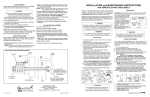
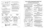
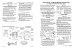
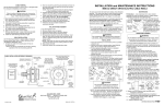
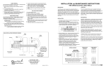
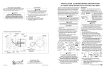
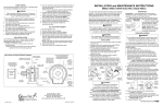
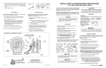
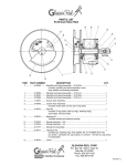
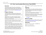
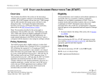
CABLE REMOVAL
Use the following procedure to remove worn or damaged cable
from reel prior to installation of new cable.
CAUTION
Failure to relieve all spring tension prior to removing
cable could result in damage to equipment or personal
injury. Follow instructions carefully.
1. Move machine serviced by reel to a position closest to
reel. Springs will still be under pre-tension at this point.
2. Turn off all electric power.
3. Lock spool to prevent turning using either a spool lock
mechanism or by tying off.
4. Disconnect cable from machine junction box.
5. Grip spool by hand and carefully release spool lock or
tie. Slowly unwind remaining tension.
6. Again lock or tie spool to prevent rotation.
7. Remove cable from spool. Loosen cable clamp and
water-tight connector. Disconnect conductors from slip ring
and remove cable.
8. Install new cable following instruction at right.
CABLE INSTALLATION
Use the following procedure to replace cable or if reel was
ordered without cable. Refer to ELECTRICAL CONNECTIONS
DRAWING, below.
1. Unspool new cable from shipping spool and lay out
to eliminate twist.
NOTE: This step is not essential, but will aid in winding
operation of the reel and prolong cable life.
ELECTRICAL CONNECTIONS
2. Feed one end of the cable through water-tight connector on
the spool hub inside the spool and into the slip ring.
(See drawing below).
NOTE: This may require that jacket of cable be stripped
to allow conductors to pass through shaft.
3. Connect individual conductors to appropriate rings on
collector using crimp fitting or similar connection method.
4. Tighten water-tight connector. Place cable clamp on cable
and securely fasten to spool disk.
5. Wind the cable onto the reel spool by hand rotating
spool in direction it turns free of spring tension.
6. Connect free end of cable to machine junction box.
7. Pretension reel and complete installation as
previously described.
COLLECTOR REPLACEMENT
1. Turn off all power to reel.
2. Remove collector cover and gasket.
3. Disconnect electric leads to and from collector.
4. Remove button plug from hole in side of housing. Insert
long 1/8” Allen wrench through hole and loosen two set
screws in collector locking collar Set screws are at 90O
to one another..
5. Slide collector off shaft.
6. Install new collector by reversing above steps.
CABLE LEADWIRES
MOVING END
LEADWIRE INPUT FIXED END
(CUSTOMER SUPPLIED)
CABLE
CABLE
CLAMP
BRUSH TERMINAL
CONNECTIONS
WATER–TIGHT
CABLE CONNECTOR
SLIP-RING
LEADWIRES ARE
NUMBER TAGGED
1
2
3
SET
SCREW
4
SLIP-RING LEAD TO
MOVING CABLE
CONNECTIONS
FRAME
1
2
3
4
SPOOL
HUB
SLIP–RINGS
COLLAR
SPOOL
DISK
SLIP–RING ENCLOSURE
• 600 VOLT AC.
NOTE:
Wire size, wire connectors, connection sequence,
and connection methods must comply with
National Electrical code and Local Electrical ordinances. If in doubt, contact a local electrical contractor or electrical inspector.
COLOR SEQUENCE FOR TYPE SO CABLE
THREE CONDUCTOR CABLE
# 1 – BLACK
# 2 – WHITE
# 3 – GREEN (ground)
FOUR THRU TWELVE CONDUCTOR CABLE
# 1 – BLACK
# 2 – WHITE
# 3 – RED
# 4 – GREEN (ground)
# 5 – ORANGE
# 6 – BLUE
# 7 – WHITE W/ BLACK TRACER
# 8 – RED W/ BLACK TRACER
# 9 – GREEN W/ BLACK TRACER
#10 – ORANGE W/ BLACK TRACER
#11 – BLUE W/ BLACK TRACER
#12 – BLACK W/ WHITE TRACER
250 VOLT DC. WATERTIGHT, DUST TIGHT.
• DO NOT EXCEED AMPERAGE RATING OF CABLE OR SLIP RING.
• NUMBER OF CIRCUITS MAY VARY FROM TWO (MINIMUM) TO 36 (MAXIMUM). FOUR CIRCUITS SHOWN.
INSTALLATION and MAINTENANCE INSTRUCTIONS
UE32 UNIVERSAL CABLE REEL-DIRECT DRIVE
All units are provided with right hand rotation unless otherwise
specified. This means that cable is pulled off spool top left or
bottom right (spool rotates clockwise to wind cable) when
viewing spring end of reel. See diagram on parts page.
Clock-type springs provide power for automatic cable take-up.
Spring must be pretensioned at time of installation to
insure that tension is applied to cable at all times. A tension
adjustment spanner wrench is provided with each reel.
WARNING
Some reels with large or multiple springs are equipped with
a ratcheted adjustment wrench. Follow separate instructions for its use. Failure to use ratcheted wrench, on reels
so equipped, could result in serious personal injury.
MAINTENANCE
Periodically: A. Use compressed air to clean collector
assembly and inside of collector housing. Inspect collector
assembly for brush wear and pitted slip rings.
B. Inspect cable for wear and check mounting bolts and
other hardware for tightness.
C. Check for broken
“IN” with 2/3 BROKEN SPRING
cable off reel–
springs by pulling about 2/3
INDICATORS
SPRING OK
cable off reel and observing
“Broken Spring Indicators” on
sides of spring canisters. See
“OUT” with 2/3
cable off reel–
Fig. 3.
SPRING
NOTE: Bearings and springs
BROKEN
are prelubricated and require
Figure 3
no periodic maintenance.
SPRING REPLACEMENT
WARNING
Do not attempt to relieve spring tension using spanner wrench. Doing so may result in personal injury.
INSTALLATION
1. Insure that machinery to be serviced by reel is at position
closest to reel.
2. Securely mount reel in desired position using 1/2"(M12)
bolts. Be sure spool is aligned with cable run.
3. Position optional cable guide, if reel is so equipped.
See COMPONENT REFERENCE DRAWING.
4. Connect free end of cable to junction box on machine or
adjust cable stop so that desired length of cable
extends from reel.
5. Remove cover plate on spring housing to expose
shaft and spring hub. (See Figure 1).
6. Insert spanner wrench into holes in spring hub (Fig 2).
Rotate wrench counterclockwise (for standard rotation).
Number of 360O turns should match last digit in model
number on serial plate. If model number includes an “R”,
reel is reverse rotation and wrench must be rotated
clockwise. (See “TO DETERMINE ROTATION OF REEL”
on parts drawing page.)
COUNTERCLOCKWISE
FOR STANDARD
ROTATION
SPRING
HOUSING
COVER
PLATE
Figure 1
SPRING
HUB
Figure 2
SPANNER
WRENCH
CAUTION
Do not exceed number of turns indicated on
serial plate. Over-tensioning can cause a
broken spring, sheared shaft or other damage.
WARNING
Do not attempt to remove spring from its housing. Clocktype springs can be dangerous to handle. Removal of
spring from housing could result in personal injury.
The unique SAFETYCHANGE® spring motor consists of a
spring and hub sealed within a housing. A replacement spring
is supplied sealed in its housing and the old unit should be discarded completely.
1. Turn off all electric power.
2. Disconnect cable from machine junction box.
3. Wind all cable onto reel to relieve all spring tension.
4. Remove inspection cover from face of spring housing.
5. Rotate spool clockwise and observe inner shaft. Shaft
should rotate clockwise and hub (with spring attached)
should remain stationary.
NOTE: Do not attempt to remove spring if resistance
is met or hub tends to rotate with shaft.
Continue to rotate spool and strike end of shaft
several sharp blows with a lead hammer or rubber mallet
until shaft rotates freely and hub remains stationary.
6. Remove (4) nuts which secure spring motor(s) to frame.
7. Slide spring motor(s) off shaft and discard.
NOTE: On multi-spring reels, be sure to remove and save
dowel pins which connect one spring hub with another. Also
remove snap rings on shaft between reel housings.
8. Install replacement spring motor(s), pawls and pawl springs.
NOTE: Pawl springs must be located between the pawls
and the deepest section of the shaft grooves. Make sure
that pawls and pawl springs are inserted flush with ends of
shaft and hub or they may rub against inspection cover.
SPOOL
SHAFT
SIDE VIEW
®
®
HUBBELL
Printed in USA
A Hubbell Company
GLEASON REEL CORP.
P.O. Box 26 • 600 South Clark St.
Mayville, WI 53050–0026
Phone 920–387–4120 • Fax 920–387–4189
Bulletin No. 045398.a
NOTE: If reel is equipped with ratcheted adjustment
wrench, follow instructions on separate sheet.
NOTE: On reels containing more than one spring, the hubs
are connected at the factory. Therefore, by tightening the
outer spring, the inside spring(s) will be tightened.
7. Remove collector cover and connect individual supply
conductors to collector terminals. See ELECTRICAL
CONNECTIONS diagram, on back page.
SPRING
HUB
(Spring not
shown)
PAWL
SPRING
Install
against flat
END VIEW
SHAFT
GROOVE
9. Tighten nuts (and extension bolts) securing spring
housing(s) to reel frame.
10. Connect free end of cable to junction box on machine or
adjust cord stop so that desired length of cord extends from reel.
11. Tension spring with spanner wrench. Refer to
INSTALLATION section.
12. Replace inspection cover.
CONTINUED ON BACK PAGE
DIRECT DRIVE UE-32 UNIVERSAL CABLE REEL
REPLACEMENT PARTS LIST
ITEM PART NO.
DESCRIPTION
QTY.
ITEM PART NO.
Always specify
SERIAL NUMBER & MODEL NUMBER
when ordering parts.
TO DETERMINE ROTATION OF REEL
DESCRIPTION
QTY.
36
32
1
042019
Vertical Frame Assy., Swivel Side
1
26
2
012140
Housing, 2" Bore Bearing
2
1
26
26
012425
Pawl Kit (35 Spring)
(Includes 2 pawls & springs)
012426
Pawl Kit (62, 75 & 80 Springs)
012427
Pawl Kit (100 Spring)
AR
41
AR
AR
3
103837
Ball Bearing, 2" Bore
4
038424
Flat Washer, M8
9
27
031484
Hex Hd. Cap Screw, M12–1.75 x 35L
4
5
028268
ESNA Lock Nut, M8–1.25
8
28
025942
Lockwasher, M12
4
6
042009
Vertical Frame Assy., Drive Side
1
29
025941
Hex Nut, M12–1.75
4
7
119114
Housing, 1.75" Bore Bearing
2
8
103823
Ball Bearing, 1.75" Bore
1
9
042030
Spool Support Hub, Drive Side
1
30
30
30
042555
042183
042182
Stand–off, 35 Springs
Stand–off, 62, 75 & 80 Springs
\Stand–off, 100 Spring\
10
012137
Stub Shaft Drive Pin
1
31
029159
\Flat Washer, M12
4
32
028502
ESNA Nut, M12–1.75
4
33
33
33
33
33
33
33
33
33
33
042727
(Includes
042725
042726
042724
042723
042732
042730
042731
042729
042728
34
G51–23
Gasket, Hub Cover
1
35
G27–42
Hub Cover, Springs
1
36
101220
Screw, #8–32 x 0.25" Lg
3
37
1
37
021762
Hub Lock Pin Kit (100 Springs)
(Includes two pins)
021761
Hub Lock Pin Kit (All Other Springs)
38
38
38
38
38
38
38
38
38
38
38
38
38
38
38
38
38
38
38
38
38
38
38
38
38
38
012285
012286
012287
012288
012289
012290
012291
012292
012293
012294
012295
012296
012297
012298
012299
012300
012376
037194
012377
037294
037295
012304
012381
012382
012383
012384
1
1
1
1
1
1
1
1
1
1
1
1
1
1
1
1
1
1
1
1
1
1
1
1
1
1
11
118322
Retaining Ring
1
12
042029
Spool Disk, U32
2
13
13
13
13
13
13
13
13
13
13
13
13
13
13
13
04271001
Wrapper Assy. Kit,
(Includes segments & hardware)
04271002
Wrapper Assy. Kit,
04271003
Wrapper Assy. Kit,
04271004
Wrapper Assy. Kit,
04271005
Wrapper Assy. Kit,
04271006
Wrapper Assy. Kit,
04271007
Wrapper Assy. Kit,
04271008
Wrapper Assy. Kit,
04271009
Wrapper Assy. Kit,
04271010
Wrapper Assy. Kit,
04271011
Wrapper Assy. Kit,
04271012
Wrapper Assy. Kit,
04271013
Wrapper Assy. Kit,
04271014
Wrapper Assy. Kit,
04271015
Wrapper Assy. Kit,
14
042068
15
Consult
Factory
6"w, 10"–12"dia. core
1
8"w, 10"–12"dia. core
10"w, 10"–12"dia. core
12"w, 10"–12"dia. core
14"w, 10"–12"dia. core
6"w, 14"–18"dia. core
8"w, 14"–18"dia. core
10"w, 14"–18"dia. core
12"w, 14"–18"dia. core
14"w, 14"–18"dia. core
6"w, 20"–26"dia. core
8"w, 20"–26"dia. core
10"w, 20"–26"dia. core
12"w, 20"–26"dia. core
14"w, 20"–26"dia. core
1
1
1
1
1
1
1
1
1
1
1
1
1
1
Spool Hub, Collector Side
1
Cable Clamp/Connector Kit
(Includes Cable Clamp, Cable Connector
& Reducer, if required, sized for cable diameter)
1
16
040784
Collector Entrance
1
17
101652
Pipe Plug
1
18
118220
Gasket, Collector Entrance
1
19
012409
1
19
19
19
19
19
012410
012411
012412
012413
012414
Collector Cover Kit (8" long)
(Includes seal ring)
Collector Cover Kit (10.5" long)
Collector Cover Kit (13" long)
Collector Cover Kit (15.5" long)
Collector Cover Kit (20.5" long)
Collector Cover Kit (28.5" long)
1
1
1
1
1
20
012458
Seal Ring Only
1
21
042067
Collector Drive Stop
1
22
028138
Lockwasher, M10
4
23
028131
Hex Hd. Cap Screw, M10–1.5 x 20L
4
24
04272201
1
24
24
24
24
04272202
04272203
04272204
04272205
Bottom Base Kit, 6" wide Wrapper
(Includes mounting hardware)
Bottom Base Kit, 8" wide Wrapper
Bottom Base Kit, 10" wide Wrapper
Bottom Base Kit, 12" wide Wrapper
Bottom Base Kit, 14" wide Wrapper
1
1
1
1
25
25
25
25
25
042152
042153
042156
042157
042554
Stub
Stub
Stub
Stub
Stub
Shaft,
Shaft,
Shaft,
Shaft,
Shaft,
1002, Direct, Standard Rotation
1001, Direct, Standard Rotation
802/622/752, Direct, Std. Rot.
801/621/751, Direct, Std. Rot.
351, Direct, Standard Rotation
1
1
1
1
1
39
39
25
25
25
25
25
042160
042161
042164
042165
042566
Stub
Stub
Stub
Stub
Stub
Shaft,
Shaft,
Shaft,
Shaft,
Shaft,
1002, Direct, Reverse Rotation
1001, Direct, Reverse Rotation
802/622/752, Direct, Rev. Rot.
801/621/751, Direct, Rev. Rot.
351, Direct, Reverse Rotation
1
1
1
1
1
40
MODEL NUMBER STRUCTURE
UE 32 80 1 - 8 3 - 10 06 - 1 - HSD
REEL TYPE
SPOOL DIAMETER
SPRING MODEL
QUANTITY SPRINGS
NUMBER POLES
AMP
CODE
ACCESSORIES
PRETENSION TURNS
SPOOL WIDTH
CORE DIAMETER
39
40
41
41
Spring Motor Kit, 35, Standard Rotation
items 20, 27, 28, 29, & 30)
Spring Motor Kit, 62, Standard Rotation
Spring Motor Kit, 75, Standard Rotation
Spring Motor Kit, 80, Standard Rotation
Spring Motor Kit, 100, Standard Rotation
Spring Motor Kit, 35, Reverse Rotation
Spring Motor Kit, 62, Reverse Rotation
Spring Motor Kit, 75, Reverse Rotation
Spring Motor Kit, 80, Reverse Rotation
Spring Motor Kit, 100, Reverse Rotation
Collector Assembly,
Collector Assembly,
Collector Assembly,
Collector Assembly,
Collector Assembly,
Collector Assembly,
Collector Assembly,
Collector Assembly,
Collector Assembly,
Collector Assembly,
Collector Assembly,
Collector Assembly,
Collector Assembly,
Collector Assembly,
Collector Assembly,
Collector Assembly,
Collector Assembly,
Collector Assembly,
Collector Assembly,
Collector Assembly,
Collector Assembly,
Collector Assembly,
Collector Assembly,
Collector Assembly,
Collector Assembly,
Collector Assembly,
042735
Ratchet Wrench Kit (35–80 Springs)
(Includes mounting hardware)
042736
Ratchet Wrench Kit (100 Springs)
AMPS
35
75
125
200
6
7
36
7
8
9
30
13
26
33
25
30
24
35
24
13
34
11
33
10
37
33
13
Standard Rotation....
P/N 042230
Reverse Rotation....
P/N 042231
33
25
23
1
22
22
23
12
16
17
SPOOL LOCK
14
All models....P/N 042227
ACCESSORIES
18
4
ROLLER CABLE
GUIDES
CABLE STOPS
5
24
38
2
2
21
DOG & RATCHET
12
15
26
39
3
TYPE
A
3.00” O.D.
TYPE
B
3.50” O.D.
PART
FITS O.D.s
TYPE
NUMBER
MIN – MAX
40
20
19
037529
037531
037532
037533
037535
037536
037537
041845
041846
B
A
A
A
B
B
B
B
B
0.44
0.62
0.75
1.06
0.75
1.06
1.39
1.56
1.88
–
–
–
–
–
–
–
–
–
0.62
0.75
1.05
1.30
1.05
1.38
1.55
1.87
2.06
HORIZONTAL
(shown)
SPOOL
WIDTH
PART
NUMBER
6"
8"
10"
12"
14"
042210
042211
042212
042213
042214
VERTICAL
COMPONENT REFERENCE DRAWING
SLIP RING
(COLLECTOR)
COVER
LINE
ENTRANCE
(NPT)
SPOOL
WRAPPER
SECTIONS
HORIZONTAL CABLE
GUIDE POSITION
(STANDARD)
SPRING
MOTOR
SPOOL
DISK
OPTIONAL VERTICAL
CABLE GUIDE
LOCATION–
REEL MOUNTED
BASE UP
1
1
1
ACCESSORY CODE
SPRING
MOTOR
(See sext page for accessories)
340O Pivot Base = P
Dog & Ratchet (ratchet lock) = D
Limit Switch = L
Horizontal Roller Guide = H
Vertical Roller Guide = V
Spool Lock = S
27
32
ar
1
28
35
31
1
ar
ar
30
34
AR
AR
AR
AR
AR
AR
AR
AR
AR
2 Pole, 35 Amp
3 Pole, 35 Amp
4 Pole, 35 Amp
6 Pole, 35 Amp
8 Pole, 35 Amp
10 Pole, 35 Amp
12 Pole, 35 Amp
14 Pole, 35 Amp
16 Pole, 35 Amp
20 Pole, 35 Amp
24 Pole, 35 Amp
30 Pole, 35 Amp
36 Pole, 35 Amp
2 Pole, 75 Amp
3 Pole, 75 Amp
4 Pole, 75 Amp
6 Pole, 75 Amp
2 Pole, 125 Amp
8 Pole, 75 Amp
3 Pole, 125 Amp
4 Pole, 125 Amp
2 Pole, 200 Amp
3 Pole, 200 Amp
4 Pole, 200 Amp
6 Pole, 200 Amp
8 Pole, 200 Amp
29
REVERSE
ROTATION
Cable is played out and retracted as shown
when viewing reel from spring motor side.
AR
042733
Spanner Wrench (35–80 Springs)
(Includes mounting hardware)
042734
Spanner Wrench (100 Springs)
CODE
3
7
12
20
STANDARD
ROTATION
AR
AR
\AR
012440
Brush Kit (35 Amp)
(Each kit includes 4 brushes and 4 fingers)
012441
Brush Kit (75 Amp)
012443
Brush Kit (125 Amp/200 Amp)
AMPACITY
CODE
31
SLIP RING
(COLLECTOR)
ASSEMBLY
SPOOL
DISK
MOUNTING BASE
OPTIONAL
VERTICAL
CABLE GUIDE
LOCATION
STANDARD
SPOOL
ROTATION
DIRECTION
TO WIND
CABLE
WHEN
VIEWED
FROM
SPRING
SIDE
OPTIONAL
HORIZONTAL
CABLE
GUIDE
LOCATION
VIEW FROM SPRING SIDE
SPOOL
WIDTH
PART
NUMBER
6"
8"
10"
12"
14"
042275
042276
042277
042278
042279
340O PIVOT BASE
SPOOL
WIDTH
PART
NUMBER
4"–6"
8"–10"
12"–14"
042284
042285
042286
CABLE REMOVAL
Use the following procedure to remove worn or damaged cable
from reel prior to installation of new cable.
CAUTION
Failure to relieve all spring tension prior to removing
cable could result in damage to equipment or personal
injury. Follow instructions carefully.
1. Move machine serviced by reel to a position closest to
reel. Springs will still be under pre-tension at this point.
2. Turn off all electric power.
3. Lock spool to prevent turning using either a spool lock
mechanism or by tying off.
4. Disconnect cable from machine junction box.
5. Grip spool by hand and carefully release spool lock or
tie. Slowly unwind remaining tension.
6. Again lock or tie spool to prevent rotation.
7. Remove cable from spool. Loosen cable clamp and
water-tight connector. Disconnect conductors from slip ring
and remove cable.
8. Install new cable following instruction at right.
CABLE INSTALLATION
Use the following procedure to replace cable or if reel was
ordered without cable. Refer to ELECTRICAL CONNECTIONS
DRAWING, below.
1. Unspool new cable from shipping spool and lay out
to eliminate twist.
NOTE: This step is not essential, but will aid in winding
operation of the reel and prolong cable life.
ELECTRICAL CONNECTIONS
2. Feed one end of the cable through water-tight connector on
the spool hub inside the spool and into the slip ring.
(See drawing below).
NOTE: This may require that jacket of cable be stripped
to allow conductors to pass through shaft.
3. Connect individual conductors to appropriate rings on
collector using crimp fitting or similar connection method.
4. Tighten water-tight connector. Place cable clamp on cable
and securely fasten to spool disk.
5. Wind the cable onto the reel spool by hand rotating
spool in direction it turns free of spring tension.
6. Connect free end of cable to machine junction box.
7. Pretension reel and complete installation as
previously described.
COLLECTOR REPLACEMENT
1. Turn off all power to reel.
2. Remove collector cover and gasket.
3. Disconnect electric leads to and from collector.
4. Remove button plug from hole in side of housing. Insert
long 1/8” Allen wrench through hole and loosen two set
screws in collector locking collar Set screws are at 90O
to one another..
5. Slide collector off shaft.
6. Install new collector by reversing above steps.
CABLE LEADWIRES
MOVING END
LEADWIRE INPUT FIXED END
(CUSTOMER SUPPLIED)
CABLE
CABLE
CLAMP
BRUSH TERMINAL
CONNECTIONS
WATER–TIGHT
CABLE CONNECTOR
SLIP-RING
LEADWIRES ARE
NUMBER TAGGED
1
2
3
SET
SCREW
4
SLIP-RING LEAD TO
MOVING CABLE
CONNECTIONS
FRAME
1
2
3
4
SPOOL
HUB
SLIP–RINGS
COLLAR
SPOOL
DISK
SLIP–RING ENCLOSURE
• 600 VOLT AC.
NOTE:
Wire size, wire connectors, connection sequence,
and connection methods must comply with
National Electrical code and Local Electrical ordinances. If in doubt, contact a local electrical contractor or electrical inspector.
COLOR SEQUENCE FOR TYPE SO CABLE
THREE CONDUCTOR CABLE
# 1 – BLACK
# 2 – WHITE
# 3 – GREEN (ground)
FOUR THRU TWELVE CONDUCTOR CABLE
# 1 – BLACK
# 2 – WHITE
# 3 – RED
# 4 – GREEN (ground)
# 5 – ORANGE
# 6 – BLUE
# 7 – WHITE W/ BLACK TRACER
# 8 – RED W/ BLACK TRACER
# 9 – GREEN W/ BLACK TRACER
#10 – ORANGE W/ BLACK TRACER
#11 – BLUE W/ BLACK TRACER
#12 – BLACK W/ WHITE TRACER
250 VOLT DC. WATERTIGHT, DUST TIGHT.
• DO NOT EXCEED AMPERAGE RATING OF CABLE OR SLIP RING.
• NUMBER OF CIRCUITS MAY VARY FROM TWO (MINIMUM) TO 36 (MAXIMUM). FOUR CIRCUITS SHOWN.
INSTALLATION and MAINTENANCE INSTRUCTIONS
UE32 UNIVERSAL CABLE REEL-DIRECT DRIVE
All units are provided with right hand rotation unless otherwise
specified. This means that cable is pulled off spool top left or
bottom right (spool rotates clockwise to wind cable) when
viewing spring end of reel. See diagram on parts page.
Clock-type springs provide power for automatic cable take-up.
Spring must be pretensioned at time of installation to
insure that tension is applied to cable at all times. A tension
adjustment spanner wrench is provided with each reel.
WARNING
Some reels with large or multiple springs are equipped with
a ratcheted adjustment wrench. Follow separate instructions for its use. Failure to use ratcheted wrench, on reels
so equipped, could result in serious personal injury.
MAINTENANCE
Periodically: A. Use compressed air to clean collector
assembly and inside of collector housing. Inspect collector
assembly for brush wear and pitted slip rings.
B. Inspect cable for wear and check mounting bolts and
other hardware for tightness.
C. Check for broken
“IN” with 2/3 BROKEN SPRING
cable off reel–
springs by pulling about 2/3
INDICATORS
SPRING OK
cable off reel and observing
“Broken Spring Indicators” on
sides of spring canisters. See
“OUT” with 2/3
cable off reel–
Fig. 3.
SPRING
NOTE: Bearings and springs
BROKEN
are prelubricated and require
Figure 3
no periodic maintenance.
SPRING REPLACEMENT
WARNING
Do not attempt to relieve spring tension using spanner wrench. Doing so may result in personal injury.
INSTALLATION
1. Insure that machinery to be serviced by reel is at position
closest to reel.
2. Securely mount reel in desired position using 1/2"(M12)
bolts. Be sure spool is aligned with cable run.
3. Position optional cable guide, if reel is so equipped.
See COMPONENT REFERENCE DRAWING.
4. Connect free end of cable to junction box on machine or
adjust cable stop so that desired length of cable
extends from reel.
5. Remove cover plate on spring housing to expose
shaft and spring hub. (See Figure 1).
6. Insert spanner wrench into holes in spring hub (Fig 2).
Rotate wrench counterclockwise (for standard rotation).
Number of 360O turns should match last digit in model
number on serial plate. If model number includes an “R”,
reel is reverse rotation and wrench must be rotated
clockwise. (See “TO DETERMINE ROTATION OF REEL”
on parts drawing page.)
COUNTERCLOCKWISE
FOR STANDARD
ROTATION
SPRING
HOUSING
COVER
PLATE
Figure 1
SPRING
HUB
Figure 2
SPANNER
WRENCH
CAUTION
Do not exceed number of turns indicated on
serial plate. Over-tensioning can cause a
broken spring, sheared shaft or other damage.
WARNING
Do not attempt to remove spring from its housing. Clocktype springs can be dangerous to handle. Removal of
spring from housing could result in personal injury.
The unique SAFETYCHANGE® spring motor consists of a
spring and hub sealed within a housing. A replacement spring
is supplied sealed in its housing and the old unit should be discarded completely.
1. Turn off all electric power.
2. Disconnect cable from machine junction box.
3. Wind all cable onto reel to relieve all spring tension.
4. Remove inspection cover from face of spring housing.
5. Rotate spool clockwise and observe inner shaft. Shaft
should rotate clockwise and hub (with spring attached)
should remain stationary.
NOTE: Do not attempt to remove spring if resistance
is met or hub tends to rotate with shaft.
Continue to rotate spool and strike end of shaft
several sharp blows with a lead hammer or rubber mallet
until shaft rotates freely and hub remains stationary.
6. Remove (4) nuts which secure spring motor(s) to frame.
7. Slide spring motor(s) off shaft and discard.
NOTE: On multi-spring reels, be sure to remove and save
dowel pins which connect one spring hub with another. Also
remove snap rings on shaft between reel housings.
8. Install replacement spring motor(s), pawls and pawl springs.
NOTE: Pawl springs must be located between the pawls
and the deepest section of the shaft grooves. Make sure
that pawls and pawl springs are inserted flush with ends of
shaft and hub or they may rub against inspection cover.
SPOOL
SHAFT
SIDE VIEW
®
®
HUBBELL
Printed in USA
A Hubbell Company
GLEASON REEL CORP.
P.O. Box 26 • 600 South Clark St.
Mayville, WI 53050–0026
Phone 920–387–4120 • Fax 920–387–4189
Bulletin No. 045398.a
NOTE: If reel is equipped with ratcheted adjustment
wrench, follow instructions on separate sheet.
NOTE: On reels containing more than one spring, the hubs
are connected at the factory. Therefore, by tightening the
outer spring, the inside spring(s) will be tightened.
7. Remove collector cover and connect individual supply
conductors to collector terminals. See ELECTRICAL
CONNECTIONS diagram, on back page.
SPRING
HUB
(Spring not
shown)
PAWL
SPRING
Install
against flat
END VIEW
SHAFT
GROOVE
9. Tighten nuts (and extension bolts) securing spring
housing(s) to reel frame.
10. Connect free end of cable to junction box on machine or
adjust cord stop so that desired length of cord extends from reel.
11. Tension spring with spanner wrench. Refer to
INSTALLATION section.
12. Replace inspection cover.
CONTINUED ON BACK PAGE