1
☞4.
☞6.
Remove cable from spool by looping over spool
flange and slip ring cover.
☞5. Remove slip ring cover
☞6. Disconnect cable leads from slip ring brush terminals.
☞7. Loosen counternut on cable connector in spool
CAUTION
Failure to relieve all spring tension prior to removing
cable could result in damage to equipment or personal
injury. Follow instructions carefully.
Pretension reel and complete installation as
described in INSTALLATION section.
☞
NOTE: These instructions are written for machine pull reels.
If installing or servicing hand pull reel, use only those steps marked with hand
All units are provided with right hand rotation unless otherwise
specified. This means that spool rotates counter-clockwise to
wind cable when viewing reel from slip ring side.
Clock-type springs provide power for cable take-up. Spring
must be pretensioned at time of installation to insure that
tension is applied to cable at all times.
INSTALLATION
1. If reel is supplying power to a machine, insure that
machinery is at position closest to reel.
WARNING
If machine pull reel, move machinery to position closest to reel
before adjusting spring tension. Adjusting tension with cable
extended may result in damage to reel or personal injury.
1.Pull about 10” of cable, allowing spool to rotate.
Unspool new cable from shipping spool and lay out
to eliminate twist.
NOTE: This step is not essential, but will aid in winding
operation of the reel and prolong cable life.
☞5.
Complete working end connections. Adjust cable stop.
Install new cable following directions below.
☞1.
☞4.
Replace slip ring cover and gasket.
SPRING ADJUSTMENT
Adjust tension by adding wraps (increasing tension) or
removing wraps (decreasing tension) from the spool.
CABLE INSTALLATION
Use the following procedure to replace cable or if reel was
ordered without cable. Refer to CABLE INSTALLATION
REFERENCE DRAWING, below.
☞2.
☞3.
Wind the cable onto the reel spool by hand rotating
spool in direction it turns free of spring tension.
(Normally counter-clockwise when viewed from
junction box side)
☞7.
☞8.
☞9.
and pull cable out.
☞8.
INSTALLATION and MAINTENANCE INSTRUCTIONS
14", 16", 19" SPRING OPERATED ELECTRIC CABLE REELS
INCREASE TENSION: Without allowing spool to rotate, hand
feed cable through hose guide until loop is large enough to
slip onto spool. Add two or three wraps until desired
tension is achieved. See Figure 3.
Remove slip ring cover.
CAUTION
If mounting overhead, provide safety chain between reel
base and mounting surface to prevent accidental reel drop.
☞2.
☞3.
Rotate spool counter-clockwise
(when viewed from slip ring side) until all cable is wound
on reel...not extending through cable guide. See fig. 1.
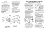
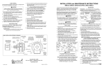
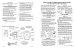
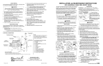
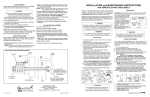
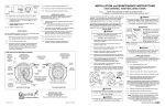
Figure 1
2. Test reel operation.
Feed one end of the cable through cable connector in
spool and into the slip ring side. (See drawing below).
Figure 3
MOUNTING
BASE
TO DECREASE
TENSION, REMOVE
WRAPS FROM
SPOOL
TO INCREASE
TENSION, ADD
WRAPS TO SPOOL
SUPPLY CABLE–ATTACH TO LEADS
FROM SLIP RING IN JUNCTION BOX
CABLE INSTALLATION REFERENCE DRAWING
LINE ENTRANCE
(NPT)
SPOOL
JUNCTION
BOX
PAYOFF
DIRECTION–
OPTIONAL
CABLE GUIDE
LOCATION
SLIP RING
COVER
REMOVE
SPRING
MOTOR
SPOOL ROTATION DIRECTION TO WIND CABLE
WHEN VIEWED FROM
JUNCTION BOX SIDE
PAYOFF
DIRECTION–
OPTIONAL
CABLE GUIDE
LOCATION
DISTRIBUTION
CABLE
CABLE
CONNECTOR
ATTACH INDIVIDUAL
DISTRIBUTION CABLE
CONDUCTORS TO
SLIP RING BRUSHES
®
HUBBELL
Printed in USA
A Hubbell Company
Pre-tension reel by rotating spool in clockwise
direction (when viewed from slip ring side). Full
360˚ turns should match last digit in model number
on serial plate. See fig. 2.
Engage ratchet lock to prevent spool from unwinding.
Feed cable end out through cable guide and pay-out
cable to maximum working length. At least one turn of
cable should remain on spool. If spool locks up prior to
reaching required length, either reel was over-tensioned
during step 5 or reel capacity has been exceeded.
Failure to correct this condition will result in shortened
spring life and possible damage to other reel components.
☞8. Attach and adjust cable stop.
9. If machine pull application or if no-lock operation is
desired, disengage ratchet lock. See following section.
☞10. Remove slip ring cover and connect individual supply
conductors to slip ring leads. Replace cover.
RATCHET LOCK
Reel is shipped with ratchet lock “engaged”. If constant spring
tension is required, lock may be disengaged by locating and
removing the selector plate anchor screw on the frame, rotating the selector plate to disengage position, and replacing and
tightening the selector plate screw.
INSTALL CABLE
THIS DIRECTION
P.O. Box 26 • 600 South Clark St.
Mayville, WI 53050–0026
Phone 920–387–4120 • Fax 920–387–4189
Bulletin No.039453.b
MAINTENANCE
Bearings and springs are prelubricated and require no
periodic maintenance.
SPRING REPLACEMENT
The unique SAFETYCHANGE® spring motor consists of a
spring sealed within a housing. A preplacement spring is
supplied sealed in its housing and the old unit should be
discarded completely.
☞1. Turn off all electric power.
☞2. Disconnect cable from working end connections.
☞3. Wind cable onto reel to relieve all spring tension.
☞4. Using a 3/16" Allen wrench, loosen socket head screw in
main shaft clamp nut. Support spool and spin nut off shaft.
WARNING
Do not attempt to remove spring from its housing. Clocktype springs can be dangerous to handle. Removal of
spring from housing could result in personal injury.
☞5.
☞6.
☞7.
☞8.
Remove entire spool and spring motor assembly
from frame.
Remove V-Ring seal from spring assembly.
Remove nuts holding spring assembly and slide spring
assembly off main shaft.
Slide new spring assembly onto shaft and reassemble
reel by reversing above steps.
☞9. Adjust spring tension. Refer to INSTALLATION, Step 5.
SLIP RING REPLACEMENT
☞1. Turn off all electric power.
☞2. Remove cover from junction box. Disconnect input wiring.
☞3. Engage ratchet lock to prevent spool from rotating.
☞4. Remove locknuts holding slip ring cover and gasket.
Remove cover.
☞5.
☞6.
Complete cable working
☞11. Turn on power to reel.
GLEASON REEL CORP.
®
PRE-TENSION–
ROTATE SPOOL
360˚ TURNS IN
LAST TWO
DIGITS OF
MODEL
NUMBER ON
SERIAL PLATE
end connections.
SPRING
MOTOR
PAYOFF
DIRECTION–
MOST
COMMON
CABLE GUIDE
POSITION
☞5.
☞6.
☞7.
SLIP RING
ASSEMBLY
SPOOL
Figure 2
WIND ALL
CABLE
ONTO
SPOOL
Figure 4
Connect individual conductors to appropriate collector
brushes on slip ring assembly using crimp fitting
or similar connection method.
☞5. Tighten cable connector in spool. Do not over-tighten.
Position cable guide. Guide must be oriented so cable pays
off reel in a straight line without bends.
☞4. Remove cable stop.
DECREASE TENSION: Without allowing spool to rotate, hand
feed cable back trhough guide to provide slack. Remove
one or two wraps from spool. See Figure 4.
Loosen counter nut on cable connector (nut is inside
slip ring housing).
Securely mount reel in desired position using 3/8"(M10)
bolts. Be sure spool centerline is aligned with cable run.
☞.
☞7.
Disconnect cable leads from slip ring terminals.
Loosen two set screws in collar using 1/8" Allen
wrench. Pull slip ring assembly off shaft.
Install new slip ring assembly on shaft and
re-assemble reel by reversing above steps.
CABLE REMOVAL
Use the following procedure to remove worn or damaged cable
from reel prior to installation of new cable.
1. Move machine serviced by reel to a position closest to
reel. Spring will still be under pre-tension at this point.
☞2. Turn off all electric power.
☞3. Disconnect cable from machine or other fixtures.
Remove cable stop and allow cable to retract onto
spool. Ensure all tension is off spring by manually
rotating spool (normally counter-clockwise when
viewed from junction box side).
CONTINUED ON BACK PAGE
ILLUSTRATED PARTS LIST
14", 16", 19" DIRECT DRIVE ELECTRIC CABLE REEL REPLACEMENT PARTS LIST
20
19
14", 16", 19" DIRECT DRIVE ELECTRIC CABLE REEL
13
17
18
Always specify SERIAL NUMBER & MODEL NUMBER when ordering parts.
36
8
10
ITEM
15
16
11
14
12
7
6
5
5
27
33
35
3
6
26 25
23
9
2
31
24
4
30
21
28
4
1
22
29
34
32
TYPE SO CABLE
RATED 600V/90OC
ELECTRICAL CONNECTIONS
CABLE LEADWIRES
MOVING END
WATER–TIGHT
CABLE GRIP
OUTPUT WIRING TO
BRUSH TERMINAL
CONNECTIONS
GROUND LUG
SLIP–RING
LEADWIRES ARE
NUMBER TAGGED
BRUSH TERMINAL CONNECTIONS
4
3
2
1
REEL
MAINSHAFT
JUNCTION BOX
AND COVER
INPUT WIRING
TO SLIP–RING
LEADWIRE
CONNECTIONS
4
SLIP–RING
COVER
3
2
1
SLIP–RINGS
SPOOL
SLIP–RING ENCLOSURE
• 600 VOLT AC. 250 VOLT DC. WATERTIGHT, DUST TIGHT.
• SLIP–RING AMPACITY RATED AT 30 AMP MAX PER RING.
• DO NOT EXCEED AMPERAGE RATING OF CABLE CONDUCTORS.
• NUMBER OF CIRCUITS MAY VARY FROM TWO (MINIMUM) TO
TWELVE (MAXIMUM). FOUR CIRCUITS SHOWN.
LEADWIRE INPUT
FIXED END
(CUSTOMER
SUPPLIED)
NOTE:
Wire size, wire connectors, connection
sequence, and connection methods must comply
with National Electrical code and Local Electrical
ordinances. If in doubt, contact a local electrical
contractor or electrical inspector.
COLOR SEQUENCE FOR TYPE SO CABLE
THREE CONDUCTOR CABLE
# 1 – BLACK
# 2 – WHITE
# 3 – GREEN (ground)
FOUR THRU TWELVE CONDUCTOR CABLE
# 1 – BLACK
# 2 – WHITE
# 3 – RED
# 4 – GREEN (ground)
# 5 – ORANGE
# 6 – BLUE
# 7 – WHITE W/ BLACK TRACER
# 8 – RED W/ BLACK TRACER
# 9 – GREEN W/ BLACK TRACER
#10 – ORANGE W/ BLACK TRACER
#11 – BLUE W/ BLACK TRACER
#12 – BLACK W/ WHITE TRACER
KIT NO.
DESCRIPTION
QTY.
1
1
1
021456
028059
021646
Frame Assembly, 14" Reel
Frame Assembly, 16" Reel
Frame Assembly, 19" Reel
1
1
1
2
021484
Clamp Nut
1
3
025032
‘V’–Ring Seal
1
4
604093
5
028132
Hex Head Capscrew, M10 x 25L
3
6
028138
Lockwasher, M10
3
7
7
7
021527
028075
023417
Mount Bracket, 14" Reel
Mount Bracket, 16" Reel
Mount Bracket, 19" Reel
1
1
1
8
8
8
024466
028071
024473
Roller Guide Assembly, 14" Reel
Roller Guide Assembly, 16" Reel
Roller Guide Assembly, 19" Reel
1
1
1
9
9
028144
028144
Lock Nut, M5 x 0.8, 14" & 16" Reel
Lock Nut, M5 x 0.8, 19" Reel
6
8
10
10
10
10
10
10
10
10
10
021488
021490
021492
021515
021517
025488
025490
028083
028085
Spring Assembly “A11”, 14" Reel
Spring Assembly “B11”, 14" Reel
Spring Assembly “C11”, 14" Reel
Spring Assembly “D11”, 16" & 19" Reels
Spring Assembly “E11”, 16" & 19" Reels
Spring Assembly “G11”, 16" & 19" Reels
Spring Assembly “H11”, 16" & 19" Reels
Spring Assembly “J11”, 16" & 19" Reels
Spring Assembly “K11”, 16" & 19" Reels
11
11
021494
022734
12
12
12
027445
028060
027401
13
13
13
ITEM
KIT NO.
DESCRIPTION
QTY.
21
21
018042
021494
Cover Gasket, 14" & 16" Reel
Cover Gasket, 19" Reel
1
1
22
22
22
22
22
021520
021521
021522
021543
022142
Slip
Slip
Slip
Slip
Slip
1
1
1
1
1
23
23
028144
028144
Lock Nut, M5 x 0.8, 14" & 16" Reel
Lock Nut, M5 x 0.8, 19" Reel
4
6
24
24
24
24
24
24
02149603
02149604
02149605
02270501
02270502
02270503
Slip
Slip
Slip
Slip
Slip
Slip
1
1
1
1
1
1
25
01555101
Grounding Lug
1
26
028139
Lockwasher, Internal Tooth
1
27
028144
Lock Nut, M5 x 0.8
1
1
1
1
1
1
1
1
1
1
28
021479
Gasket, Junction Box
1
29
021480
Junction Box
1
30
028131
Hex Head Capscrew, M10 x 20L
3
31
018042
Cover Gasket
1
32
018043
Junction Box Cover
1
Spring Gasket, 14" & 16" Reels
Spring Gasket, 19" Reel
1
1
33
028136
Taptite Screw, M6 x 1 6L
4
34
028146
Lock Nut, M10 x 1.5
3
Shaft, 14" Reel
Shaft, 16" Reel
Shaft, 19" Reel
1
1
1
35
028140
Lockwasher, M6
027412
02806603
027408
Spool Assembly, 14" Reel
Spool Assembly, 16" Reel
Spool Assembly, 19" Reel
1
1
1
36
See Nameplate
14
14
14
027444
028061
027409
Flange Bushing, 14" Reel
Flange Bushing, 16" Reel
Flange Bushing, 19" Reel
1
1
1
15
028144
Lock Nut, M5 x 0.8
4
16
16
107185
027406
Retaining Ring, 14" & 16" Reel
Retaining Ring, 19" Reel
1
1
17
027456
Thrust Washer, 14" & 16" Reel
18
021513
19
20
20
20
Locking Dog Repair Kit
(Includes mounting hardware)
1
Ring Assembly, 1–4 Pole, 30A
Ring Assembly, 5–8 Pole, 30A
Ring Assembly, 9–12 Pole, 30A
Ring Assembly, 1–4 Pole, 55A
Ring Assembly, 1–4 Pole, 75A
(19"Reel Only)
Ring
Ring
Ring
Ring
Ring
Ring
Cover,
Cover,
Cover,
Cover,
Cover,
Cover,
1–4 Pole, 14" & 16"
5–8 Pole, 14" & 16"
9–12 Pole, 14" & 16"
1–4 Pole, 19" Reel
5–8 Pole, 19" Reel
9–12 Pole, 19" Reel
4
Cable, Model Number**
1
OPTIONAL ACCESSORIES
022450
Cable Stop, 0.38"–0.50" Dia. Cable
Option
022451
Cable Stop, 0.50"–0.75" Dia. Cable
Option
022452
Cable Stop, 0.75"–1.00" Dia. Cable
Option
022217
Swivel Base, 14" Reel
Option
1
028056
Swivel Base, 16" Reel
Option
Counter Nut
1
022220
Swivel Base, 19" Reel
Option
104336
O-Ring
1
022805
021510
021511
Cable Connector, 0.38–0.50 Cable Dia. 1
Cable Connector, 0.50–0.70 Cable Dia. 1
Cable Connector, 0.70–1.00 Cable Dia. 1
MODEL NUMBER CODE
Reel
Cable
Series
C14 - A
Number
Conductors
03
-
Spring
B11
Pretension
Required
02
CABLE CHART
A=16 AWG
B=14 AWG
C=12 AWG
D=10 AWG
E=8 AWG, Type W
F=8 AWG, Grounded
ILLUSTRATED PARTS LIST
14", 16", 19" DIRECT DRIVE ELECTRIC CABLE REEL REPLACEMENT PARTS LIST
20
19
14", 16", 19" DIRECT DRIVE ELECTRIC CABLE REEL
13
17
18
Always specify SERIAL NUMBER & MODEL NUMBER when ordering parts.
36
8
10
ITEM
15
16
11
14
12
7
6
5
5
27
33
35
3
6
26 25
23
9
2
31
24
4
30
21
28
4
1
22
29
34
32
TYPE SO CABLE
RATED 600V/90OC
ELECTRICAL CONNECTIONS
CABLE LEADWIRES
MOVING END
WATER–TIGHT
CABLE GRIP
OUTPUT WIRING TO
BRUSH TERMINAL
CONNECTIONS
GROUND LUG
SLIP–RING
LEADWIRES ARE
NUMBER TAGGED
BRUSH TERMINAL CONNECTIONS
4
3
2
1
REEL
MAINSHAFT
JUNCTION BOX
AND COVER
INPUT WIRING
TO SLIP–RING
LEADWIRE
CONNECTIONS
4
SLIP–RING
COVER
3
2
1
SLIP–RINGS
SPOOL
SLIP–RING ENCLOSURE
• 600 VOLT AC. 250 VOLT DC. WATERTIGHT, DUST TIGHT.
• SLIP–RING AMPACITY RATED AT 30 AMP MAX PER RING.
• DO NOT EXCEED AMPERAGE RATING OF CABLE CONDUCTORS.
• NUMBER OF CIRCUITS MAY VARY FROM TWO (MINIMUM) TO
TWELVE (MAXIMUM). FOUR CIRCUITS SHOWN.
LEADWIRE INPUT
FIXED END
(CUSTOMER
SUPPLIED)
NOTE:
Wire size, wire connectors, connection
sequence, and connection methods must comply
with National Electrical code and Local Electrical
ordinances. If in doubt, contact a local electrical
contractor or electrical inspector.
COLOR SEQUENCE FOR TYPE SO CABLE
THREE CONDUCTOR CABLE
# 1 – BLACK
# 2 – WHITE
# 3 – GREEN (ground)
FOUR THRU TWELVE CONDUCTOR CABLE
# 1 – BLACK
# 2 – WHITE
# 3 – RED
# 4 – GREEN (ground)
# 5 – ORANGE
# 6 – BLUE
# 7 – WHITE W/ BLACK TRACER
# 8 – RED W/ BLACK TRACER
# 9 – GREEN W/ BLACK TRACER
#10 – ORANGE W/ BLACK TRACER
#11 – BLUE W/ BLACK TRACER
#12 – BLACK W/ WHITE TRACER
KIT NO.
DESCRIPTION
QTY.
1
1
1
021456
028059
021646
Frame Assembly, 14" Reel
Frame Assembly, 16" Reel
Frame Assembly, 19" Reel
1
1
1
2
021484
Clamp Nut
1
3
025032
‘V’–Ring Seal
1
4
604093
5
028132
Hex Head Capscrew, M10 x 25L
3
6
028138
Lockwasher, M10
3
7
7
7
021527
028075
023417
Mount Bracket, 14" Reel
Mount Bracket, 16" Reel
Mount Bracket, 19" Reel
1
1
1
8
8
8
024466
028071
024473
Roller Guide Assembly, 14" Reel
Roller Guide Assembly, 16" Reel
Roller Guide Assembly, 19" Reel
1
1
1
9
9
028144
028144
Lock Nut, M5 x 0.8, 14" & 16" Reel
Lock Nut, M5 x 0.8, 19" Reel
6
8
10
10
10
10
10
10
10
10
10
05059801
05059802
05059803
05059804
05059806
05059809
05059810
05059811
05059813
Spring Assembly “A11”, 14" Reel
Spring Assembly “B11”, 14" Reel
Spring Assembly “C11”, 14" Reel
Spring Assembly “D11”, 16" & 19" Reels
Spring Assembly “E11”, 16" & 19" Reels
Spring Assembly “G11”, 16" & 19" Reels
Spring Assembly “H11”, 16" & 19" Reels
Spring Assembly “J11”, 16" & 19" Reels
Spring Assembly “K11”, 16" & 19" Reels
11
11
021494
022734
12
12
12
027445
028060
027401
13
13
13
ITEM
KIT NO.
DESCRIPTION
QTY.
21
21
018042
021494
Cover Gasket, 14" & 16" Reel
Cover Gasket, 19" Reel
1
1
22
22
22
22
22
602733
602734
602735
602736
602737
Slip
Slip
Slip
Slip
Slip
1
1
1
1
1
23
23
028144
028144
Lock Nut, M5 x 0.8, 14" & 16" Reel
Lock Nut, M5 x 0.8, 19" Reel
4
6
24
24
24
24
24
24
02149603
02149604
02149605
02270501
02270502
02270503
Slip
Slip
Slip
Slip
Slip
Slip
1
1
1
1
1
1
25
01555101
Grounding Lug
1
26
028139
Lockwasher, Internal Tooth
1
27
028144
Lock Nut, M5 x 0.8
1
1
1
1
1
1
1
1
1
1
28
021479
Gasket, Junction Box
1
29
021480
Junction Box
1
30
028131
Hex Head Capscrew, M10 x 20L
3
31
018042
Cover Gasket
1
32
018043
Junction Box Cover
1
Spring Gasket, 14" & 16" Reels
Spring Gasket, 19" Reel
1
1
33
028136
Taptite Screw, M6 x 1 6L
4
34
028146
Lock Nut, M10 x 1.5
3
Shaft, 14" Reel
Shaft, 16" Reel
Shaft, 19" Reel
1
1
1
35
028140
Lockwasher, M6
4
36
See Nameplate
Cable, Model Number**
1
027412
02806603
027408
Spool Assembly, 14" Reel
Spool Assembly, 16" Reel
Spool Assembly, 19" Reel
1
1
1
14
14
14
027444
028061
027409
Flange Bushing, 14" Reel
Flange Bushing, 16" Reel
Flange Bushing, 19" Reel
1
1
1
022450
Cable Stop, 0.38"–0.50" Dia. Cable
Option
022451
Cable Stop, 0.50"–0.75" Dia. Cable
Option
15
028144
Lock Nut, M5 x 0.8
4
022452
Cable Stop, 0.75"–1.00" Dia. Cable
Option
16
16
107185
027406
Retaining Ring, 14" & 16" Reel
Retaining Ring, 19" Reel
1
1
022217
Swivel Base, 14" Reel
Option
028056
Swivel Base, 16" Reel
Option
17
027456
Thrust Washer, 14" & 16" Reel
1
022220
Swivel Base, 19" Reel
Option
18
021513
Counter Nut
1
19
104336
O-Ring
1
20
20
20
022805
021510
021511
Locking Dog Repair Kit
(Includes mounting hardware)
1
Cable Connector, 0.38–0.50 Cable Dia. 1
Cable Connector, 0.50–0.70 Cable Dia. 1
Cable Connector, 0.70–1.00 Cable Dia. 1
Ring Assembly, 1–4 Pole, 30A
Ring Assembly, 5–8 Pole, 30A
Ring Assembly, 9–12 Pole, 30A
Ring Assembly, 1–4 Pole, 55A
Ring Assembly, 1–4 Pole, 75A
(19"Reel Only)
Ring
Ring
Ring
Ring
Ring
Ring
Cover,
Cover,
Cover,
Cover,
Cover,
Cover,
1–4 Pole, 14" & 16"
5–8 Pole, 14" & 16"
9–12 Pole, 14" & 16"
1–4 Pole, 19" Reel
5–8 Pole, 19" Reel
9–12 Pole, 19" Reel
OPTIONAL ACCESSORIES
MODEL NUMBER CODE
Reel
Cable
Series
C14 - A
Number
Conductors
03
-
Spring
B11
Pretension
Required
02
CABLE CHART
A=16 AWG
B=14 AWG
C=12 AWG
D=10 AWG
E=8 AWG, Type W
F=8 AWG, Grounded
☞4.
☞6.
Remove cable from spool by looping over spool
flange and slip ring cover.
☞5. Remove slip ring cover
☞6. Disconnect cable leads from slip ring brush terminals.
☞7. Loosen counternut on cable connector in spool
CAUTION
Failure to relieve all spring tension prior to removing
cable could result in damage to equipment or personal
injury. Follow instructions carefully.
Pretension reel and complete installation as
described in INSTALLATION section.
☞
NOTE: These instructions are written for machine pull reels.
If installing or servicing hand pull reel, use only those steps marked with hand
All units are provided with right hand rotation unless otherwise
specified. This means that spool rotates counter-clockwise to
wind cable when viewing reel from slip ring side.
Clock-type springs provide power for cable take-up. Spring
must be pretensioned at time of installation to insure that
tension is applied to cable at all times.
INSTALLATION
1. If reel is supplying power to a machine, insure that
machinery is at position closest to reel.
WARNING
If machine pull reel, move machinery to position closest to reel
before adjusting spring tension. Adjusting tension with cable
extended may result in damage to reel or personal injury.
1.Pull about 10” of cable, allowing spool to rotate.
Unspool new cable from shipping spool and lay out
to eliminate twist.
NOTE: This step is not essential, but will aid in winding
operation of the reel and prolong cable life.
☞5.
Complete working end connections. Adjust cable stop.
Install new cable following directions below.
☞1.
☞4.
Replace slip ring cover and gasket.
SPRING ADJUSTMENT
Adjust tension by adding wraps (increasing tension) or
removing wraps (decreasing tension) from the spool.
CABLE INSTALLATION
Use the following procedure to replace cable or if reel was
ordered without cable. Refer to CABLE INSTALLATION
REFERENCE DRAWING, below.
☞2.
☞3.
Wind the cable onto the reel spool by hand rotating
spool in direction it turns free of spring tension.
(Normally counter-clockwise when viewed from
junction box side)
☞7.
☞8.
☞9.
and pull cable out.
☞8.
INSTALLATION and MAINTENANCE INSTRUCTIONS
14", 16", 19" SPRING OPERATED ELECTRIC CABLE REELS
INCREASE TENSION: Without allowing spool to rotate, hand
feed cable through hose guide until loop is large enough to
slip onto spool. Add two or three wraps until desired
tension is achieved. See Figure 3.
Remove slip ring cover.
CAUTION
If mounting overhead, provide safety chain between reel
base and mounting surface to prevent accidental reel drop.
☞2.
☞3.
Rotate spool counter-clockwise
(when viewed from slip ring side) until all cable is wound
on reel...not extending through cable guide. See fig. 1.
Figure 1
2. Test reel operation.
Feed one end of the cable through cable connector in
spool and into the slip ring side. (See drawing below).
Figure 3
MOUNTING
BASE
TO DECREASE
TENSION, REMOVE
WRAPS FROM
SPOOL
TO INCREASE
TENSION, ADD
WRAPS TO SPOOL
SUPPLY CABLE–ATTACH TO LEADS
FROM SLIP RING IN JUNCTION BOX
CABLE INSTALLATION REFERENCE DRAWING
LINE ENTRANCE
(NPT)
SPOOL
JUNCTION
BOX
PAYOFF
DIRECTION–
OPTIONAL
CABLE GUIDE
LOCATION
SLIP RING
COVER
REMOVE
SPRING
MOTOR
SPOOL ROTATION DIRECTION TO WIND CABLE
WHEN VIEWED FROM
JUNCTION BOX SIDE
PAYOFF
DIRECTION–
OPTIONAL
CABLE GUIDE
LOCATION
DISTRIBUTION
CABLE
CABLE
CONNECTOR
ATTACH INDIVIDUAL
DISTRIBUTION CABLE
CONDUCTORS TO
SLIP RING BRUSHES
®
HUBBELL
Printed in USA
A Hubbell Company
Pre-tension reel by rotating spool in clockwise
direction (when viewed from slip ring side). Full
360˚ turns should match last digit in model number
on serial plate. See fig. 2.
Engage ratchet lock to prevent spool from unwinding.
Feed cable end out through cable guide and pay-out
cable to maximum working length. At least one turn of
cable should remain on spool. If spool locks up prior to
reaching required length, either reel was over-tensioned
during step 5 or reel capacity has been exceeded.
Failure to correct this condition will result in shortened
spring life and possible damage to other reel components.
☞8. Attach and adjust cable stop.
9. If machine pull application or if no-lock operation is
desired, disengage ratchet lock. See following section.
☞10. Remove slip ring cover and connect individual supply
conductors to slip ring leads. Replace cover.
RATCHET LOCK
Reel is shipped with ratchet lock “engaged”. If constant spring
tension is required, lock may be disengaged by locating and
removing the selector plate anchor screw on the frame, rotating the selector plate to disengage position, and replacing and
tightening the selector plate screw.
INSTALL CABLE
THIS DIRECTION
P.O. Box 26 • 600 South Clark St.
Mayville, WI 53050–0026
Phone 920–387–4120 • Fax 920–387–4189
Bulletin No.039453.b
MAINTENANCE
Bearings and springs are prelubricated and require no
periodic maintenance.
SPRING REPLACEMENT
The unique SAFETYCHANGE® spring motor consists of a
spring sealed within a housing. A preplacement spring is
supplied sealed in its housing and the old unit should be
discarded completely.
☞1. Turn off all electric power.
☞2. Disconnect cable from working end connections.
☞3. Wind cable onto reel to relieve all spring tension.
☞4. Using a 3/16" Allen wrench, loosen socket head screw in
main shaft clamp nut. Support spool and spin nut off shaft.
WARNING
Do not attempt to remove spring from its housing. Clocktype springs can be dangerous to handle. Removal of
spring from housing could result in personal injury.
☞5.
☞6.
☞7.
☞8.
Remove entire spool and spring motor assembly
from frame.
Remove V-Ring seal from spring assembly.
Remove nuts holding spring assembly and slide spring
assembly off main shaft.
Slide new spring assembly onto shaft and reassemble
reel by reversing above steps.
☞9. Adjust spring tension. Refer to INSTALLATION, Step 5.
SLIP RING REPLACEMENT
☞1. Turn off all electric power.
☞2. Remove cover from junction box. Disconnect input wiring.
☞3. Engage ratchet lock to prevent spool from rotating.
☞4. Remove locknuts holding slip ring cover and gasket.
Remove cover.
☞5.
☞6.
Complete cable working
☞11. Turn on power to reel.
GLEASON REEL CORP.
®
PRE-TENSION–
ROTATE SPOOL
360˚ TURNS IN
LAST TWO
DIGITS OF
MODEL
NUMBER ON
SERIAL PLATE
end connections.
SPRING
MOTOR
PAYOFF
DIRECTION–
MOST
COMMON
CABLE GUIDE
POSITION
☞5.
☞6.
☞7.
SLIP RING
ASSEMBLY
SPOOL
Figure 2
WIND ALL
CABLE
ONTO
SPOOL
Figure 4
Connect individual conductors to appropriate collector
brushes on slip ring assembly using crimp fitting
or similar connection method.
☞5. Tighten cable connector in spool. Do not over-tighten.
Position cable guide. Guide must be oriented so cable pays
off reel in a straight line without bends.
☞4. Remove cable stop.
DECREASE TENSION: Without allowing spool to rotate, hand
feed cable back trhough guide to provide slack. Remove
one or two wraps from spool. See Figure 4.
Loosen counter nut on cable connector (nut is inside
slip ring housing).
Securely mount reel in desired position using 3/8"(M10)
bolts. Be sure spool centerline is aligned with cable run.
☞.
☞7.
Disconnect cable leads from slip ring terminals.
Loosen two set screws in collar using 1/8" Allen
wrench. Pull slip ring assembly off shaft.
Install new slip ring assembly on shaft and
re-assemble reel by reversing above steps.
CABLE REMOVAL
Use the following procedure to remove worn or damaged cable
from reel prior to installation of new cable.
1. Move machine serviced by reel to a position closest to
reel. Spring will still be under pre-tension at this point.
☞2. Turn off all electric power.
☞3. Disconnect cable from machine or other fixtures.
Remove cable stop and allow cable to retract onto
spool. Ensure all tension is off spring by manually
rotating spool (normally counter-clockwise when
viewed from junction box side).
CONTINUED ON BACK PAGE