1
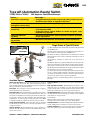
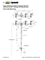
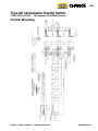
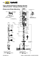
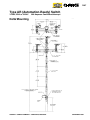
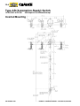
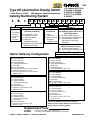
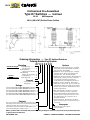
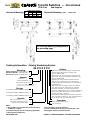
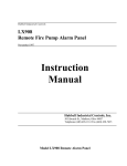
® ® 14A 14A-1 POWER SYSTEMS, INC. OVERHEAD SWITCHES Gang-Operated Type AR, Type D7 and Type D6 Warranty - Material The Chance Company warrants all products sold by it to be merchantable (as such term is defined in the Uniform Commercial Code) and to be free from defects in material and workmanship. Buyer must notify the Company promptly of any claim under this warranty. The Buyer's exclusive remedy for breach of this warranty shall be the repair or replacement, F.O.B. factory, at the Company's option, of any product defective under the warranty which is returned to the Company within one year from the date of shipment. NO OTHER WARRANTY, WHETHER EXPRESS OR ARISING BY OPERATION OF LAW, COURSE OF DEALING, USAGE OF TRADE OR OTHERWISE IMPLIED, SHALL EXIST IN CONNECTION WITH THE COMPANY'S PRODUCTS OR ANY SALE OR USE THEREOF. The Company shall in no event be liable for any loss of profits or any consequential or special damages incurred by Buyer. The Company's warranty shall run only to the first Buyer of a product from the Company, from the Company's distributor, or from an original equipment manufacturer reselling the Company's product, and is non-assignable and non-transferable and shall be of no force and effect if asserted by any person other than such first Buyer. This warranty applies only to the use of the product as intended by Seller and does not cover any misapplication or misuse of said product. Warranty - Application The Chance Company does not warrant the accuracy of and results from product or system performance recommendations resulting from any engineering analysis or study. This applies regardless of whether a charge is made for the recommendation, or if it is provided free of charge. Responsibility for selection of the proper product or application rests solely with the purchaser. In the event of errors or inaccuracies determined to be caused by The Chance Company, its liability will be limited to the re-performance of any such analysis or study. NOTE: Because Hubbell has a policy of continuous product improvement, we reserve the right to change design and specifications without notice. Copyright 2007 Hubbell Incorporated • 210 North Allen Street • Centralia, MO 65240 USA HUBBELL / CHANCE COMPANY – CENTRALIA, MISSOURI Printed in USA © SEPTEMBER 2007 ® ® 14A-2 POWER SYSTEMS, INC. U.S. Patents 6,207,919; 6,215,082; 6,281,460; 6,409,135; 6,459,053; 6,541,717; 6,818,846; 6,946,607. Type AR (Automation-Ready) Switch 14.4kV, 25kV or 34.5kV 900 Amperes Continuous/Interrupt Description The Hubbell unitized Type AR switch is a distribution-level, loadbreak, gang-operated side-break switch designed to meet not only today’s needs but well into utilities’ future of distribution automation. Designed for nominal system voltages of 14.4kV and 25kV three- and four-wire systems and 34.5kV grounded-wye systems. The Type AR switch is available with a variety of options, and in ratings for present and planned requirements. To minimize field installation time, the Type AR switch is pre-assembled, adjusted and mounted on a crossarm. Installation time is even faster for a Type AR switch with the hook stick-operation option. Horizontal Mounting Variations and Configurations The Type AR switch is available in five basic configurations: •Horizontal •Vertical •Phase-over-Phase •Delta •Inverted All feature clockwise opening and are operable by torsional or reciprocating controls as well a hookstick operation option (full-length down-the-pole control or crossarm-mounted hook stick-operation control). 1. Full-length down-the-pole controls consist of Torsional swing-handle operation for Horizontal, Delta and Inverted switches and Reciprocating pump-handle operation for Vertical and Phase-over-Phase switches. (Standard Duty or Heavy Duty conrols are available for Vertical and Phase-over-Phase switches.) Switch open or close positions locking provisions are provided. 2. Crossarm-mounted hook stick-operation controls provide pull-to-open / pull-to-close switch with maximum target hook stick accessibility. (Torsional down-the-pole control shown) Features: All three phase switches feature a four-link overtoggle mechanism to assure locked closed blades, mechanical advantage for easier open and close operation, and "snap" feedback to the operator. Inverted Mounting (Hook stick control shown) PhaseoverPhase Mounting Delta Mounting Vertical Mounting (Reciprocating down-the-pole control shown) (Reciprocating down-the-pole control shown) (Hook stick control shown) Type AR Switch Ratings Nominal Voltage/Lightning Impulse Withstand .... 14.4 kV/110 kV, 25 kV/150 kV or 34.5 kV grounded-wye/150 kV Continuous Current ................................................. 900 amperes Interrupting Current ............................................... 900 amperes Peak Withstand Current...........................................65,000 amperes peak Short Time Withstand Current...........3 sec.............25,000 amperes, symmetrical Fault Making: 1 time ............................................25,000 amperes, asymmetrical 3 time ............................................20,000 amperes, asymmetrical Dead-ending: .............................................................8,000-lb. working load Ice Breaking: ............................................................3/4-in. thick, opening and closing SEPTEMBER 2007 HUBBELL / CHANCE COMPANY – CENTRALIA, MISSOURI ® ® 14A-3 POWER SYSTEMS, INC. Type AR (Automation-Ready) Switch 14.4kV, 25kV or 34.5kV 900 Amperes Continuous/Interrupt Feature — Advantage — • Automation-ready design • Compatible with today’s D/A environment by adding a motor operator and RTU of your choice, or upgrade in the future • Meets present and future operation requirements • 900-amp continuous and interruption current rating • Four-link overtoggle mechanism • Hook stick operation capability • Unitized, pre-assembled construction • Four mounting arrangements • Mechanical advantage reduces operating torque to the lowest level in the industry to date • Overtoggle feature assures blades are closed and gives “snap” feedback to the operator • Minimizes installation time, reduces possible vandalism, eliminates control adjustments • Minimizes installation time and eliminates control adjustments • Meets various utility installation requirements 7 Interrupter 5 8 6 4 2 3 1 Available Options Hook stick Operation The Type AR switch can be operated by a hook stick operation. This option eliminates control pipe sections down the pole and their attendant adjustment during installation and maintenance. Extra Pipe The extra pipe section includes guide, coupling, and all hardware for attachment. Single Phase of Type AR Switch (1) Hot-rolled steel base formed into a channel and galvanized per ASTM A153. (2) Hot-rolled crank lever provides high strength and corrosion resistance. Galvanized per ASTM A153. (3) Delrin® bushing coupled with a cast aluminum rotating shaft eliminates the need for lubrication during the life of the switch. (4) Insulators available in 2.25" bolt circle, porcelain or polymer. (5) High-conductivity copper with phosphorous-bronze backup springs and copper-tungsten fault-closing tips provide reliable contact areas. Silver-to-silver current-transfer points. (6) Blade formed from hard-drawn, high-conductivity copper for maximum current carrying capability. (7) Interrupter provides current interruption without external arc or flame. High-strength polyurethane material for strength, weatherability and UV resistance. Bolted tonguein-groove mounting ensures positive alignment. (8) Polycarbonate ice shield helps protect contacts from ice build up. Crossarm Braces Crossarm braces may be specified as an option. ESP™ polymer Insulators The distribution insulators, 2.25inch bolt circle, are available in a U.S.-manufactured ESP polymer design. They are light weight, durable, and they offer long-term performance in every type of environment. Extension Links When deadending to the AR switch, extension links must be used to give needed clearance. The end clevis has a slotted hole for inserting the machine bolt without having to remove the extension bar. The extension links supplied are 14 inches long, hot-dip galvanized, and REA accepted. Catalog No. C2070112; six required per switch. Terminal Connectors Catalog No. ATC1343, fortified cadmium-plated aluminum parallel-groove clamp can be supplied with switches. Six per switch. Surge Arrester Brackets Three brackets can be supplied for mounting six surge arresters (utility supplied) for overvoltage protection. Control Insulator One 150 kV LIW (Lightining Impulse Withstand - BIL) polymer insulator in vertical control pipe. Sensor Brackets Extension Brackets can be supplied, or added to the AR Switch, to allow for the additon of line voltage/current sensors. HUBBELL / CHANCE COMPANY – CENTRALIA, MISSOURI Cable Range: Minimum No. 2 solid copper [0.258 inch (6.55 mm)] to maximum 500 kcmil copper [0.811 inch (20.60 mm)]. Captive Hardware Two stainless-steel spline bolts pressed into each terminal pad, nuts and lockwashers included. SEPTEMBER 2007 ® ® 14A-4 POWER SYSTEMS, INC. Type AR (Automation-Ready) Switch 14.4kV, 25kV or 34.5kV 900 Amperes Continuous/Interrupt Horizontal Mounting SEPTEMBER 2007 HUBBELL / CHANCE COMPANY – CENTRALIA, MISSOURI ® ® 14A-5 POWER SYSTEMS, INC. Type AR (Automation-Ready) Switch 14.4kV, 25kV or 34.5kV 900 Amperes Continuous/Interrupt Vertical Mounting HUBBELL / CHANCE COMPANY – CENTRALIA, MISSOURI SEPTEMBER 2007 ® ® 14A-6 POWER SYSTEMS, INC. Type AR (Automation-Ready) Switch 14.4kV, 25kV or 34.5kV 900 Amperes Continuous/Interrupt Phase-over-Phase Mounting 6-1/2" 165 MM 7-1/4" 184 MM (17.1KV)16-1/4" 413 MM (29KV)19-1/4" 489 MM "A" "A" ALL MOUNTING HARDWARE 5/8"(16 MM)DIA 25" 635 MM 6" 152 MM 10" 254 MM 14" 356 MM SIDE VIEW 2-1/2" 64 MM 32" 813 MM VIEW "A"-"A" 23-1/2" 597 MM 4"(102 MM)SQUARE CROSSARM GALV STEEL OR FIBERGLASS 3/4"(19 MM)NPS GALV PIPE OR 1"(25 MM)FIBERGLASS ROD 81-1/2" 2070 MM 14" 356 MM ENF OF CROSSARM TOP SECTION 1-1/4"(32 MM) NPS GALV PIPE OR FIBERGLASS 32" 813 MM 11-1/2" 292 MM 8-1/2" 216 MM 99" 2515 MM 86-3/4" 2203 MM TOP SECTION 3/4"(19 MM) NPS GALV PIPE OR 1"(25 MM) FIBERGLASS ROD GUIDES COUPLINGS 84" 2134 MM (TYPICAL) ALL LOWER SECTIONS 3/4"(19 MM) NPS GALV PIPE 85" 216 MM (TYPICAL) ALL LOWER SECTIONS 1-1/4"(32 MM) NPS GALV PIPE STEADY LEVER "B-B" (TYPICAL) 6" 152 MM (TYPICAL) "B" 28 FT(8.5 M)MAX WITHOUT ADDITION OF PIPE SECTION "B" GROUND STRAP RECIPROCATING HANDLE 6" 152 MM OPEN AND CLOSED LOCKING PROVISIONS HEAVY DUTY CONTROL TYPE "T" AND "G" SEPTEMBER 2007 NAMEPLATE STANDARD CONTROL TYPE "S" AND "F" AS REQUIRED BY USER HUBBELL / CHANCE COMPANY – CENTRALIA, MISSOURI ® ® 14A-7 POWER SYSTEMS, INC. Type AR (Automation-Ready) Switch 14.4kV, 25kV or 34.5kV 900 Amperes Continuous/Interrupt Delta Mounting HUBBELL / CHANCE COMPANY – CENTRALIA, MISSOURI SEPTEMBER 2007 ® ® 14A-8 POWER SYSTEMS, INC. Type AR (Automation-Ready) Switch 14.4kV, 25kV or 34.5kV 900 Amperes Continuous/Interrupt Inverted Mounting SEPTEMBER 2007 HUBBELL / CHANCE COMPANY – CENTRALIA, MISSOURI ® ® 14A-9 POWER SYSTEMS, INC. Type AR (Automation-Ready) Switch 14.4kV, 25kV or 34.5kV 900 Amperes Continuous/Interrupt Catalog Numbering System A R Position 1: U.S. Patents 6,207,919; 6,215,082; 6,281,460; 6,409,135; 6,459,053; 6,541,717; 6,818,846; 6,946,607. 1 X X X X X X X X X X X X Position 2: Position 3: Position 4: Crossarm/InterPhase Shaft Standard Controls — Pipe sizes Configuration on drawings, pages 14A-4 thru -8 1 = Horizontal (All configurations) S = Steel 1 = 110 porcelain (17.1kV) 2 = Vertical S = All Steel Vertical Sections F = Fiberglass 3 = 110 polymer (17.1kV) 3 = Ø-over-Ø F = One Fiberglass Vertical Section M = Steel crossarm, 4 = 150 polymer (29kV) 4 = Delta H =Vertical Controls replaced fiberglass 6 = 150 polymer 5 = Inverted with Hook stick Operating interphase shaft (38kV grounded-wye) Mechanism 7 = 150 polymer Long Leak (39.6") Heavy-Duty Controls — 11⁄4" IPS (38kV grounded-wye) (Vertical and Ø-over-Ø only) T = All Steel Vertical Sections G = One Fiberglass Vertical Section Insulation, kV Impulse (maximum system kV) Option Tables by Configuration Horizontal and Inverted Switches B = Sensor Brackets * C = Control Insulator † H = Captive Hardware L = Surge Arrester Brackets * P = Extra Pipe * PP = Two Extra Pipes S = Steel Crossarm Brace, only one supplied † T = Terminal Connectors (ATC 1343) W = Wood Crossarm Brace, only one supplied X = Extension Links Phase-over-Phase Switch, S & F Controls B = Sensor Brackets * C = Control Insulator † H = Captive Hardware L = Surge Arrester Brackets * P = Extra Pipe * PP = Two Extra Pipes † T = Terminal Connectors (ATC 1343) X = Extension Links Phase-over-Phase Switch, S & F Controls B = Sensor Brackets * C = Control Insulator † H = Captive Hardware L = Surge Arrester Brackets * R = Extra Pipe * RR = Two Extra Pipes † T = Terminal Connectors (ATC 1343) X = Extension Links Positions 5 through 12: See Option Tables for each Configuration Vertical Switch, S & F Controls B = Sensor Brackets * C = Control Insulator H = Captive Hardware L = Surge Arrester Brackets * P = Extra Pipe * PP = Two Extra Pipes † T = Terminal Connectors (ATC 1343) Vertical Switch, T & G Controls B = Sensor Brackets * D = Control Insulator H = Captive Hardware L = Surge Arrester Brackets * R = Extra Pipe * RR = Two Extra Pipes † T = Terminal Connectors (ATC 1343) Delta Switch B = Sensor Brackets * C = Control Insulator † H = Captive Hardware L = Surge Arrester Brackets * P = Extra Pipe * PP = Two Extra Pipes † T = Terminal Connectors (ATC 1343) X = Extension Links *Options C, P, R, PP and RR do not apply when Hook Stick Operated Control is supplied. Options H and T, Captive Hardware and Terminal Connectors, cannot be ordered together. † Replacement Parts C8180001 E8181000P Interrupter for all Mounting Configurations Live Parts for all kV Ratiings and Mounting Configurations HUBBELL / CHANCE COMPANY – CENTRALIA, MISSOURI SEPTEMBER 2007 ® ® 14A-10 POWER SYSTEMS, INC. Unitized and Pre-Assembled Type D7 Switches — Unitized 15 to 38 kV 600 Amperes Three mounting variations of the D7 are available. Horizontal Mounting Riser Pole Mounting Phase-over-Phase Mounting Application and Ratings The Chance unitized D7 is a distribution-level, gang-operated, side-break switch for 15 through 38 kV applications. It is pre-assembled, adjusted, and mounted on a common support at the factory for three-phase service. D7 switches meet a continuous-current rating of 600 amperes, a momentary rating of 40,000 amperes, a three-second short time current rating of 25,000 amperes, and applicable NEMA and ANSI standards. It is available in 15 kV (110 kV LIW*), 27 kV (150 kV LIW*), 34.5kV (150kV LIW*) or 38 kV (200 kV LIW*). The D7 is a 600-ampere loadbreak switch with the Duogap® expulsion interrupters. With the Duogap, the D7 is capable of switching load currents up to 600 amperes, with full recovery voltage across the switch, and interrupting transformer magnetizing and line-charging currents. This switch may be used for disconnecting, line sectionalizing, circuit breaker bypassing, and isolating. *Lightning Impulse Withstand (BIL) Convenient Installation Field installation time of this pre-assembled switch is greatly reduced below what is usually required to install separate gang-operated distribution level switches. The three-phase unit is conveniently raised in one piece to its mounting position, secured to the pole, control sections attached, and field adjustment made. Proper synchronization and phase spacing have been made at the factory. Unitized switches are installed in 2 to 4 hours, compared to non-unitized switches that take 6 to 8 hours. One-lift installation cuts time and cost of separate gang-operated, distributionlevel switches. SEPTEMBER 2007 HUBBELL / CHANCE COMPANY – CENTRALIA, MISSOURI ® ® 14A-11 POWER SYSTEMS, INC. Unitized and Pre-Assembled Type D7 Switches — Unitized 15 to 38 kV 600 Amperes Design Features The jaw socket and hinge terminal castings of the D7 are bronze with tin-plated NEMA terminal pads. The blade is a round tubular copper with flattened ends to allow for a silver/copper contact. A four-point silver plated contact is supplied on the jaw end to make the switch easier to open and close. An all-copper current path is provided. Interrupters Chance 15.5, 27 and 38 kV Duogap expulsion interrupters . Chance Duogap® expulsion interrupter converts any D7 to a loadbreak switch. Built-in sockets on each switch accept the interrupter. The Duogap may be ordered with the switch or may be hotstick-installed for load management conversion. For more on the Duogap, see Bulletin No. 14-9405. Terminal Pads, Arcing Horns Two-hole NEMA terminal pads are standard. The D7 terminal pads are bronze with tin-plating to provide low-resistance efficient current transfer. A stainless steel arcing horn is provided to pick up load current, thus preventing burning or arc pitting on the main contacts. Insulators The Vee configuration of the insulators simulates a low profile with less bulk and a pleasing visual appearance. The gray-tone insulator for the unitized D7 switch is NEMA 3-inch BC. 15 thru 34.5 kV Switch Base and Bearings The base castings consist of high strength, high corrosion resistant aluminum alloy. This lightweight aluminum is comparable to bronze in almost all metal technical categories, such as: ultimate tensile, tensile yield, elongation, hardness, modulus of elasticity, thermal conductivity, and electrical conductivity. Bearings are high-strength, high-density Delrin, for smooth pivotal action. Conductors are dead-ended to each individual switch base. Pull-off holes are designed for a 6,000-lb. working load rating. The switch frame is limited to an unequal loading of 700 lb. Common Support The 4 x 4-inch common support member is furnished in either galvanized-steel or fiberglass tubing. The “interphase” shaft which connects the three rotating insulators is constructed of the same material as the crossarm. Controls Controls are either all metal or metal with a vertical fiberglass section. Three options combine the metal or insulated interphase shaft with the metal or fiberglass common support. The arcing horn will pick up load current upon closing to prevent burning or arc pitting on the main contact surfaces. HUBBELL / CHANCE COMPANY – CENTRALIA, MISSOURI SEPTEMBER 2007 ® ® 14A-12 POWER SYSTEMS, INC. Unitized and Pre-Assembled Type D7 Switches — Unitized 15 to 38 kV 600 Amperes Riser Pole Mounting Dimensions (inches) D C kV E 15 36 15 36 17 48 27 42 17 *34.5 48 42 *150 kV LIW (Lightning Impulse Withstand) SEPTEMBER 2007 HUBBELL / CHANCE COMPANY – CENTRALIA, MISSOURI ® ® 14A-13 POWER SYSTEMS, INC. Unitized and Pre-Assembled Type D7 Switches — Unitized 15 to 38 kV Horizontal Mounting 600 Amperes Dimensions (inches) D C E kV 15 36 36 15 17 48 42 27 17 42 *34.5 48 *150 kV LIW (Lightning Impulse Withstand) Horizontal Mounting 38 kV — 200 BIL HUBBELL / CHANCE COMPANY – CENTRALIA, MISSOURI SEPTEMBER 2007 ® ® 14A-14 POWER SYSTEMS, INC. Unitized and Pre-Assembled Type D7 Switches — Unitized 15 to 38 kV 600 Amperes Phase-over-Phase Mounting Phase-over-Phase Mounting Dimensions (inches) B A kV 36 84 15 48 108 27 48 108 *34.5 *150 kV LIW (Lightning Impulse Withstand) SEPTEMBER 2007 38 kV — 200 kV LIW (Lightning Impulse Withstand) HUBBELL / CHANCE COMPANY – CENTRALIA, MISSOURI ® ® 14A-15 POWER SYSTEMS, INC. Unitized and Pre-Assembled Type D7 Switches — Unitized 15 to 38 kV 600 Amperes 15kV (110kV LIW*) Switch Phase Outline 4" x 4" CROSSARM STEEL OR FIBERGLASS 27kV (150kV LIW*) Switch Phase Outline 4" x 4" CROSSARM STEEL OR FIBERGLASS 34.5 kV (150kV LIW*) Switch Phase Outline 4" x 4" CROSSARM STEEL OR FIBERGLASS *Lightning Impulse Withstand HUBBELL / CHANCE COMPANY – CENTRALIA, MISSOURI SEPTEMBER 2007 ® ® 14A-16 POWER SYSTEMS, INC. Unitized and Pre-Assembled Type D7 Switches — Unitized 38 kV 600 Amperes 38 kV (200 LIW*) Switch Phase Outline Ordering Information — Type D7 Unitized Switches Catalog Numbering System D7 X X X X X X Mounting Horizontal Upright Vertical Phase-over-Phase CCW Opening ------------ H CW Opening ------------ X CCW Opening Extra pole clearance - R CW Opening Extra pole clearance - T CCW Opening ------------V CCW Opening ------------ P Support Galvanized Steel --- S Fiberglass ------------ E Ratings 15 kV/110 kV LIW* NEMA Porcelain Insulator ---1 15 kV/110 kV LIW* NEMA Polymer Insulator -----4 27 kV/150 kV LIW* NEMA Porcelain Insulator ---2 38 kV/200 kV LIW* NEMA Porcelain Insulator ---3 38 kV/200 kV LIW* NEMA Polymer Insulator ---- 6 34.5 kV/150 kV LIW* NEMA Porcelain Insulator--7 Controls All steel controls (Used with steel support only) --A Fiberglass universal section and steel interphase shaft (Used with steel support only) ----------------- B Fiberglass universal section and interphase rod (used with Fiberglass support only) ----------------- C Options A-Additional 10 ft. operating pipe, coupling, and guide bracket. Horizontal mounting only. Cat. No. E8012729P. B-Additional 10 ft. operating pipe, coupling, and pipe guide. Phase-Over-Phase and Vertical only. Cat. No. E8012729P. D-Lightning arrester brackets. Horizontal and Vertical only. Specify Cat. No. C8011014 for complete mounting assembly for six distribution class lightning arresters. E-Lighting arrester brackets. Phase-Over- Phase only. Specify Cat. No. C8011381 for complete mounting assembly for six distribution class arresters; C8011380 for three arrester application. Q-One 150 kV LIW* insulator in vertical controls. Specify porcelain or polymer. T-Six fortified cadmium-plated aluminum parallel-groove terminal connectors. Cat. No. ATC1343 for one connector, No. 2 through 500 kcmil. U-Crossarm braces. Wood braces for fiber- glass crossarm (pair), steel brace for steel crossarms. Interrupter L -With Duogap® Interrupter N -No interrupter NOTE: (1) 200 kV LIW* not available with vertical mounting or fiberglass crossarm. (2) Consult factory for motor operators. *Lightning Impulse Withstand SEPTEMBER 2007 HUBBELL / CHANCE COMPANY – CENTRALIA, MISSOURI ® ® 14A-17 POWER SYSTEMS, INC. Type D6 Switches — Non-Unitized 15 to 38 kV 600 Amperes Application and Ratings The Chance Type D6 is a distribution-level, gang-operated, side-break switch for 15 through 38kV applications. D6 switches meet a continuous-current rating of 600 amperes, a momentary rating of 40,000 amperes, a three-second shorttime current rating of 25,000 amperes, and all applicable NEMA and ANSI standards. It is available in 15 kV (110 kV LIW*), 27 kV (150 kV LIW*) and 38 kV (200 kV LIW*). The unit is a 600-ampere loadbreak switch with Duogap® expulsion interrupters. Each switch comes prefitted with a socket to accept the Duogap. Orders also may specify switches come without the interrupters. With the Duogap, D6 is capable of switching load currents up to 600 amperes, with full recovery voltage across the switch, and interrupting transformer magnetizing and line-charging currents. The D6 switch may be used for disconnecting, line sectionalizing, circuit breaker bypassing, and isolating. Design Features D6 jaw socket and hinge terminal pads are bronze castings with stainless steel supports. The blade is round tubular copper with flattened ends to allow for a silver/copper contact. Silver contacts are used to ensure smooth, easy operation. Bases and Bearings The switch base for 38 kV (200 kV LIW*) is galvanized-steel hat-section. A sealed, greaseless main bearing supports the rotating insulator. The stainless-steel balls are encased in a high-strength, heat-treated aluminum housing for maintenance-free operation. The switch base for 15 kV (110 kV LIW*) and 27 kV (150 kV LIW*) is extruded aluminum channel and the bearings are high-density Delrin. Insulators 15 kV (110 kV LIW*) Switch Phase The Sky-Glaze® insulator is gray porcelain NEMA 3-inch BC. Blade Opening All side-break D6 switches open in the counter-clockwise direction. Terminal Pads, Arcing Horn NEMA-standard, two-hole terminal pads accept aluminum or bronze connectors. Tin-plated bronze D6 pads reduce resistance to assure efficient current transfer. A stainless steel arcing horn picks up load current, preventing burning or arc pitting on the main contacts. Interrupters Chance Duogap® expulsion interrupter makes the D6 a loadbreak switch. Built-in sockets on each switch accept the interrupter. The Duogap may be ordered with the switch or may be hotstick-installed for load management conversion. For more on the Duogap, see Bulletin No.14-9405. 27 kV (150 kV LIW*) Switch Phase 38 kV (200 kV LIW*) Switch Phase Alternate Mounting Arrangements The standard D6 switch design allows for a multitude of mounting and control configurations. The switch can be mounted horizontally or vertically. Controls can be installed on any side of the pole or off the switch ends for structure mount. Some common configurations are shown below. Consult factory for other requirements. *Lightning Impulse Withstand HUBBELL / CHANCE COMPANY – CENTRALIA, MISSOURI SEPTEMBER 2007 ® ® 14A-18 15 to 38 kV POWER SYSTEMS, INC. Horizontal Mounting Type D6 Switches — Non-Unitized kV 15 27 Dimensions (inches) E F G 36 15 36 48 17 42 600 Amperes Horizontal Mounting 38 kV — 200 kV LIW* For alternate mounting configurations, see preceding page. Ordering Information Catalog Numbering System Mounting D6 X X X X X X Phase-over-Phase CCW Opening ---P Horizontal Upright CCW Opening -- H Vertical (Riser Pole) CCW Opening ---V Support None ------------------ 0 * Galvanized Steel --- S (Horizontal mount only) * Supports are bundled with the control pipe separate from the switch crate. Ratings 15 kV/110 kV LIW* NEMA Insulator - 1 27 kV/150 kV LIW* NEMA Insulator - 2 38 kV/200 kV LIW* NEMA Insulator - 3 Controls All steel controls -------------------- A Fiberglass universal section and steel interphase shaft --- B NOTE: 1. 200 kV KIW* is not available with vertical mounting or fiberglass support. 2. Consult factory for structure mounting applications. Options A-Additional 10 ft. operating pipe, coupling, and guide bracket. Horizontal mounting only. Cat. No. E8012729P. B-Additional 10 ft. operating pipe, coupling, and pipe guide. Phase-Over-Phase and Vertical only. Cat. No. E8012729P. D-Lightning arrester brackets. Horizontal and Vertical only. Specify Cat. No. C8011014 for complete mounting assembly for six distribution class arresters. E-Lighting arrester brackets. Phase-Over-Phase only. Specify Cat. No. C8011381 for complete mounting assembly for six distribution-class arresters; C8011380 for three arrester application. Q-One 150 kV LIW* insulator in vertical controls. Specify porcelain or polymer. T-Six fortified cadmium-plated aluminum parallel groove terminal connectors. Cat. No. ATC1343 for one connector, No. 2 through 500 kcmil. Interrupter L - With Duogap® Interrupter N - No interrupter 3. Consult factory for motor operators. 4. If non-standard phase spacing is required, please provide length of interphase control desired. *Lightning Impulse Withstand SEPTEMBER 2007 HUBBELL / CHANCE COMPANY – CENTRALIA, MISSOURI ® ® 14A-19 POWER SYSTEMS, INC. HUBBELL / CHANCE COMPANY – CENTRALIA, MISSOURI SEPTEMBER 2007 ® ® 14A-20 POWER SYSTEMS, INC. Web: http://www.hubbellpowersystems.com E-mail: [email protected] UNITED STATES MEXICO HUBBELL POWER SYSTEMS, INC. 210 N. Allen Centralia, Mo 65240-1395 Phone: 573-682-5521 Fax: 573-682-8714 e-mail: [email protected] HUBBELL DE MEXICO, S.A. DE. CV Av. Coyoacan No. 1051 Col. Del Valle 03100 Mexico, D.F. Phone: 52-55-9151-9999 Fax: 52-55-9151-9988 e-mail: [email protected] ™ SEPTEMBER 2007 ® ® ® HUBBELL / CHANCE COMPANY – CENTRALIA, MISSOURI ®