1
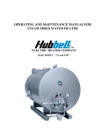
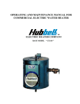
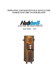
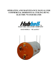
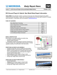
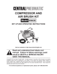
OPERATING AND MAINTENANCE MANUAL FOR
COMMERCIAL INDIRECT POWERED WATER
HEATER
ELECTRIC HEATER COMPANY
BASE MODEL “ T ”
HUBBELL
ELECTRIC HEATER COMPANY
P.O. BOX 288
STRATFORD, CT 06615
PHONE: (203) 378-2659
FAX:
(203) 378-3593
INTERNET: http://www.hubbellheaters.com/
-- IMPORTANT -Always reference the full model number and serial number when calling the factory.
WARNING / CAUTION
1. Tank is to be completely filled with water and all air is to be vented before energizing.
2. Due to the rigors of transportation, all connections should be checked for tightness before heater
is placed in operation.
3. Safety relief valve must be installed in tapping provided.
4. KEEP AWAY FROM LIVE ELECTRICAL CIRCUITS.
Do not perform any maintenance, make any adjustments, or replace any components inside the
control panel with the high voltage power supply turned on. Under certain circumstances,
dangerous potentials may exist even when the power supply is off. To avoid casualties, always
turn the power supply safety switch to off, turn the charge or ground the circuit before
performing any maintenance or adjustment procedure.
5. The unit is designed to operate at pressure not more than 150 psi.
6. Generalized instructions and procedures cannot anticipate all situations. For this reason, only
qualified installers should perform the installations. A qualified installer is a person who has
licensed training and a working knowledge of the applicable codes regulation, tools, equipment,
and methods necessary for safe installation of an electric resistance water heater. If questions
regarding installation arise, check your local plumbing and electrical inspectors for proper
procedures and codes. If you cannot obtain the required information, contact the company.
2
TABLE OF CONTENTS
SECTION
TITLE
PAGE #
I
GENERAL DESCRIPTION AND CONSTRUCTION
5
II
INSTALLATION
8
III
SCHEDULED MAINTENANCE AND OPERATION
12
IV
TROUBLESHOOTING
15
V
SERVICING AND REPLACEMENT OF PARTS
16
VI
MISCELLANEOUS CHARTS AND FORMULAS
25
3
4
SECTION I - GENERAL DESCRIPTION AND CONSTRUCTION
GENERAL DESCRIPTION
This book describes a packaged boiler water powered indirect water heater that is a stationary, selfcontained unit. The complete assembly on a standard unit consists of the storage tank, immersion
heating coil, and an ASME rated combination temperature and pressure safety relief valve. Optional
equipment may be supplied with your unit. Please consult the product drawing for details specific to
your assembly. The unit is factory assembled, insulated, jacketed, wired, tested, and ready for electrical
and plumbing service connections.
CONSTRUCTION
TANK
The standard storage tank is constructed of steel and internally lined with specially formulated
Hydrastone cement to a ½-inch minimum thickness. The tank is designed for a maximum allowable
working pressure of 150 psi (300 psi TP).
TANK CONNECTIONS
The heater is supplied with separate cold water and hot water connections. Water entering the cold
water inlet is deflected by means of a baffle within the tank. The hot water outlet includes a built in heat
trap to prevent hot water from radiating out from the heater. A ¾-inch FNPT connection is located on
the side of the heater for mounting a combination safety temperature and pressure relief valve. An
overflow line should be installed from the relief valve outlet to a floor drain. A ¾-inch GHT connection
is supplied for draining. See drawing for locations and sizes.
OUTER SHELL AND INSULATION
The tank is encapsulated in 2-inch thick polyurethane foam insulation. The insulation is protected by a
high impact non-corroding colorized composite protective jacket.
HEATING COIL
The water heater is supplied with a high quality, factory installed, high efficiency, single walled,
copper finned heating coil designed for a maximum working pressure of 150 psi. The tubing is
installed in a heavy-duty fabricated steel head with threaded NPT connections. Each assembly is
fastened to a corresponding tank flange using a gasket and hex head steel bolts and nuts. Double
walled tubing may be supplied as an option.
5
CONTROL THERMOSTAT
The water heater is supplied with an immersion thermostatic
switch. The thermostat can be adjusted through a range of 120°
- 140° F.
OPTIONAL BACK-UP ELECTRIC HEATING SYSTEM
Back-up Electric Heating Element
The water heater may be supplied with an electric immersion heating element assembly(s). Each
assembly is fastened to a corresponding tank flange using a gasket and four (4) 3/8-16 x 1-inch long
hex head steel bolts and nuts. See drawing for voltage and power ratings.
Control Thermostat
The water heater may be supplied with either a surface mounted or immersion thermostatic switch to
control the back-up electric heating system. See drawing for specific details. The surface mounted
thermostat can be adjusted through a range of 110° - 170° F. The immersion thermostat can be adjusted
through a range of 100° - 190° F. Both thermostats are adjustable with a flat tip screwdriver.
Surface Mounted Thermostat
Immersion Thermostat
6
Temperature High Limit Switch
As a safety device, either a surface mounted high temperature cut-off switch with manual reset, factory
set at 190° F, or an immersion high temperature cut-off switch with manual reset, factory set at 180° F,
may be provided. In the event of an over-temperature condition, the thermostat will disengage the
power from the back-up electric heating system. The high limit must be manually reset thereafter to
restart the heater.
Manual Reset
Surface Mounted High
Temperature Cut-Off Switch
Immersion High Temperature Cut-Off Switch
7
SECTION II – INSTALLATION
WARNING / CAUTION
DO NOT TURN ON THE BOILER WATER SUPPLY to this equipment until heater is completely
filled with water and all air has been released. If the heater is NOT filled with water when the power
is turned on, damage to the heating coil may result.
For protection against excessive pressures and temperatures, local codes require the installation of a
temperature-and-pressure (T&P) relief valve certified by a nationally recognized laboratory that
maintains periodic inspection of production of listed equipment of materials, as meeting the
requirements for Relief Valves and Automatic Gas Shutoff for Hot Water Supply Systems. ANSI
Z21.22-1971. THE CUSTOMER IS RESPONSIBLE TO PROTECT PROPERTY AND
PERSONNEL FROM HARM WHEN THE VALVE FUNCTIONS.
All water heaters have a risk of leakage at some unpredictable time. IT IS THE CUSTOMER'S
RESPONSIBILITY TO PROVIDE A CATCH PAN OR OTHER ADEQUATE MEANS, SO THAT
THE RESULTANT FLOW OF WATER WILL NOT DAMAGE FURNISHINGS OR PROPERTY.
WATER HEATER PLACEMENT
1. Place the heater on a solid foundation in a clean, dry location nearest to the point of most
frequent hot water use. If the heater is to be raised off the floor, the entire bottom of the
heater should be supported by a solid surface.
2. The water heater should be protected from freezing and waterlines insulated to reduce energy
and water waste.
3. Leave a minimum of 18” clearance for element withdrawal, if necessary.
INSTALL THE HEAT EXCHANGER COIL
1. Remove the access panel. (See diagram below).
2. Insert the heat exchanger and align the holes in the cover plate with the slotted holes in the
flange. (Note: align heat exchanger pipe connections with the opening in the access panel.)
3. WARNING: THE NYLON BUSHINGS MUST BE IN THE OPENINGS BEFORE THE
BOLTS ARE INSERTED. FAILURE TO DO THIS WILL VOID THE WARRANTY.
4. Insert and secure the bolts to the nuts one at a time in the following manner.
a. Place the nut behind the slotted flange opening.
b. Hold the nut in place with one hand – insert the bolt with the other.
c. Thread the bolt into the nut and tighten.
d. Proceed to the next opening.
e. NOTE: BE SURE TO PLACE BOLTS IN ALL OF THE OPENINGS.
8
PIPING INSTALLATION
NOTE: The most effective means for preventing deterioration from accelerated corrosion due to
galvanic and stray current is the installation of dielectric fittings/unions. The installation of these
fittings is the responsibility of the installing contractor.
1. All integral components have been properly sized to meet design conditions. Piping to the
unit should be sized to meet the design conditions, as dictated by good engineering practices.
2. Connect boiler water supply and return lines to heating coil assembly.
3. Connect the cold water inlet and hot water outlet to the appropriate connections as shown;
refer to the drawing for location and sizes.
9
4. Install the combination temperature and pressure safety relief valve in the tapping provided.
Note that this is required by law for safety considerations.
Outlet to floor drain
Install into provided tapping
Manual Release
Lever
Temperature Probe
Temperature and Pressure Relief Valve
5. Install a relief valve overflow pipe to a nearby floor drain. CAUTION: No valve of any type
should be installed between the relief valve and tank or in the drain line.
10
ELECTRICAL INSTALLATION
1. Connect electrical wiring from boiler controls and circulator pump to immersion thermostat.
2. If supplied with a back-up electric heating element; enter electric enclosure with properly
sized feeder leads. Be sure to properly ground the water heater. Install these power leads into
the box lugs on the terminal block.
3. Torque screws per torque chart included in Section VI.
4. All other electrical connections are made at the factory; therefore, no other electrical
connections are necessary.
FILLING THE HEATER
1. Completely close the drain valve.
2. Open the highest hot water faucet to allow all air to escape from piping.
3. Open the valve to the cold water inlet and allow the heater and piping system to completely
fill, as indicated by a steady flow of water from the open faucet.
FINAL CHECKS
1. Check all connections for tightness.
2. Ensure that all the above steps are completed
3. After the water is heated for the first time, monitor the water temperature as described in
Section III, Quarterly Inspection.
11
SECTION III - SCHEDULED MAINTENANCE AND OPERATION
WARNING / CAUTION
Before performing any maintenance procedure, make certain boiler water and electric supply is OFF
and cannot accidentally be turned on.
MAINTENANCE AND OPERATION
The water heater is automatic in its operation. It will maintain a full tank of water at the temperature
setting of the thermostat. The water heater should not be turned on without first making sure that the
tank is full of water and that all air has been released.
FREEZING
The tank should be fully drained in the event the boiler water has been turned off and if there is
danger of freezing.
QUARTERLY INSPECTION
1. Monitor thermostat
a. Let water heater completely heat to a designated thermostat setting.
b. After thermostat satisfies (that is, when the thermostat actually clicks off), draw water from
heater.
c. Compare water temperature of drawn water to the temperature setting of the thermostat when
it satisfies. Normal variation between the two points is approximately + 5°F.
d. If these two readings do not coincide within acceptable tolerances and verification has been
made of the accuracy of the temperature-reading gauge, replace the thermostat.
2. Lift test lever on relief valve and let water run through valve for a period of approximately 10
seconds. This will help flush away any sediment that might build up in water passageways.
3. Inspect heating coil flange for leakage as follows:
a. Remove heating coil housing cover.
b. Visually inspect heating coil gasket for evidence of leaks.
c. Rub finger around gasket that is between the heating coil and tank flange for any evidence of
moisture. If moisture is present or a water drip is observed, follow procedure outlined in
Section V.
4. Check for loose electrical connections. Tighten as necessary.
12
ANNUAL INSPECTION
1. Flush tank as follows
a.
b.
c.
d.
Shut off power supply.
Close valve on hot water outlet piping.
Open valve on drain piping.
Cold water inlet line pressure will be strong enough to flush sediment from the bottom of the
tank out through the drain. Let water run for 3-4 minutes.
e. Close drain valve.
f. Open hot water valve.
g. Turn power supply ON.
2. Units subject to fouling or scaling should be cleaned periodically. A marked increase in pressure
drop and/or reduction in performance usually indicates cleaning is necessary.
3. To clean inside of tubes, remove all heads and covers. (Caution: Do not loosen heads until you
are sure all pressure is off the equipment, and the unit is drained).
4. Clean the unit using the following methods.
a. Circulate hot fresh water at a reasonable velocity.
b. Try spraying with water hose.
c. Consult with manufacturers of cleaning compounds and chemicals. They will check the
nature of the deposit, recommend the right cleaning compound, and in many cases provide
equipment and personnel for a complete cleaning job.
5. If the unit is dismantled for any reason, it should be reassembled using new gaskets.
6. Do not tighten bolts until gaskets are properly seated.
7. When tightening bolts in the element head, tighten the bolts in a criss-cross pattern. This will
evenly distribute pressure around the flange, and help prevent warping.
13
SECTION IV – TROUBLESHOOTING
Symptom
Gradual loss of heating
capacity.
Overheating.
Immediate loss of heating
capacity.
Excessive vibration.
Water hammer.
Probable Cause
Tubes are fouled.
Corrective Action / Remedy
Clean tubes per Section III, annual
scheduled maintenance.
Excess silt in bottom of tank. Drain and flush tank per Section III ,
annual scheduled maintenance.
Ruptured tube(s) in heating
Remove / replace heating coil.
coil.
Thermostat needs adjusting. Adjust thermostat
Circulator not operating.
Repair or replace per separate O&M.
Blockage in return line.
Clean blockage from return line.
High rate of flow beyond
design conditions.
Under sized piping to the
unit.
Undersized return lines.
Insufficient slope on return
lines causing backup.
Consult factory.
Re-pipe lines to unit using proper
sized lines.
Re-pipe return line using proper sized
lines.
Increase slope on return lines.
* Red symptom indicates that equipment should be shut down immediately and cause of malfunction
corrected before unit is re-started or serious damage may result.
14
BACK-UP ELECTRCIAL HEATER SYSTEM (if supplied)
Symptom
No hot water
Probable Cause
Circuit breaker tripped at source.
High limit switch tripped.
Loose wires.
Heating element inoperable.
Low line voltage.
Faulty thermostat.
Water temperature
below settings at all
times
Faulty thermostat.
Heating element not working on
all phases
Heater improperly sized
Relief valve
discharges
continuously
Excessive temperature or
pressure in tank
Corrective Action / Remedy
Reset circuit breaker.
Reset high limit switch.
Tighten wires. Torque screws per torque
chart included in Section VI.
Check heating element operation by
clamping an Amprobe around each wire to
the element. The ampere reading should
agree with the nameplate ‘AMP’ figure.
Have source electrical system checked by
an electrician.
Move thermostat dial through full range. A
definite ‘click’ should be heard. If not,
replace thermostat.
Check thermostat adjustment. Monitor
thermostat as described in Section III,
Quarterly Inspection. Replace if necessary.
Check to see that heating element is
working on all phases, by checking the
resistance (ohms) value for each element
and comparing with expected rating.
Verify heater is properly sized for the flow
rate and temperature rise of your system.
Replace elements with proper size as
necessary.
Temperature and pressure relief valves are
made to operate if the water temperature
exceeds 210°F or water pressure exceeds
the pressure rating of the safety relief valve.
If trouble is excessive temperature, then
thermostat is not shutting off at the right
setting and thermostat must be replaced.
15
SECTION V - SERVICING & REPLACEMENT OF PARTS
WARNING / CAUTION
Before servicing or replacing any part make sure to turn the power supply switch to the OFF position.
RELIEF VALVE
1. Disconnect power from unit.
2. Shut off incoming water and boiler water supply.
3. Lift test lever on relief valve to relieve pressure in tank.
4. Disconnect overflow piping.
5. Unscrew relief valve, remove assembly and replace with new one.
6. Connect overflow piping.
7. Turn on incoming water supply and check for leaks.
8. Turn safety switch to ON position.
Test Lever
Overflow Piping Outlet
Tank Connection
Temperature Probe
16
HEATING COIL
1.
2.
3.
4.
Disconnect power from unit.
Shut off incoming cold and boiler water supply.
Attach hose to drain connection.
Lift manual release lever on relief valve to let air into system or break union on outgoing
water line.
5. Drain water from tank.
6. Disconnect supply and return lines from heating coil.
7. Remove bolts securing the heating coil to the tank flange.
Tank Flange
Gasket
Heating Coil Assembly
Supply and Return
Connections
Bolts
8. Withdraw heating coil assembly and remove gasket.
9. Install new gasket and insert new heating coil assembly.
10. Secure heating coil assembly to tank flange using bolt tightening pattern and torque as shown
in Section III.
11. Reconnect supply and return lines to heating coil.
12. Fill tank and check around gasket for any leaks.
17
SURFACE TEMPERATURE HIGH LIMIT CUT-OFF (if supplied)
1. Disconnect power from unit.
2. Remove access cover.
3. Disconnect the four (4) 14 gauge wires or three (3) 14 gauge wires and a jumper, as required.
Control Wires
4. Remove the two (2) mounting screws or disconnect from thermostat, as required.
Mounting Screws
5. Replace control and install new high limit switch by performing above steps in reverse order.
18
IMMERSION TEMPERATURE HIGH LIMIT CUT-OFF (if supplied)
1. Disconnect power from unit.
2. Remove access cover.
3. Remove high limit cover screw and cover.
Cover
Cover Screw
Reset Tab
4. Disconnect the two (2) 14 gauge wires.
Wires
Capillary Tube
5. Remove capillary tube and bulb from
thermowell
6. Remove two (2) mounting screws.
Mounting Screws
7. Remove control and install new high limit switch by performing above steps in
reverse order. (Note: Be sure to place capillary tube into slot in base prior to installing cover.)
19
HEATING ELEMENT (if supplied)
1. Disconnect power from unit.
2. Shut off incoming water supply.
3. Attach hose to drain connection.
4. Lift manual release lever on relief valve to let air into system or break union on outgoing
water line.
5. Drain water from tank.
6. Disconnect the wires from the heating element terminals.
Tank Flange
Wires
7. Remove the 3/8-16 nuts.
8. Withdraw element assembly and remove gasket.
Gasket
Element Assembly
Nuts
9. Install new gasket and insert new heating element.
10. Rewire element according to type of unit as shown below.
11. Fill tank and check around gasket for any leaks.
20
L1
L1
L2
L3
L2
1
3
2
1
3
2
4
1
4
2
1
2
1
3
2
Single Element Operation
1
4
2
3 Ø Open Delta Wiring for Simultaneous Operation
21
L1
1
2
L2
L1
3
4
1
1
2
3
4
1
4
4
2
2
1
1
2
2
Interlocked for Non-Simultaneous Operation
22
L2
Non-Interlocked for Simultaneous Operation
SURFACE MOUNTED THERMOSTAT (if supplied)
1. Disconnect power from unit.
2. Remove access cover and locate thermostat.
3. Disconnect the two (2) or three (3) 14 gauge wires and jumpers, as required.
Control Wires
4. Remove two (2) mounting screws and disconnect from high limit cut-off, if required.
Mounting Screws
5. Replace thermostat using the reverse procedure.
23
IMMERSION THERMOSTAT (if supplied)
1. Disconnect power from unit.
2. Remove access cover and locate thermostat.
3. Remove high limit cover screw and cover.
Cover
Cover Screw
4. Disconnect the two (2) or three (3)
14 gauge wires, as required.
Wires
Capillary Tube
5. Remove capillary tube and bulb from
thermowell.
6. Remove two (2) mounting screws.
Mounting Screws
7. Replace thermostat using reverse procedure. (Note: Be sure to
place capillary tube into slot in base prior to installing cover.)
24
SECTION VI – MISCELLANEOUS CHARTS AND FORMULAS
FORMULAS
25
26
T Model – Coil Curves