1
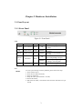
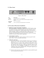
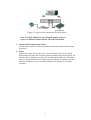
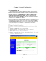
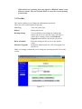
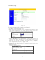
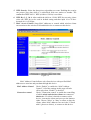
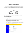
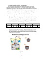
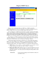
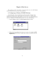
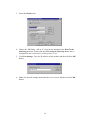
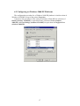
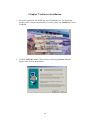
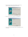
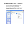
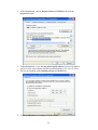
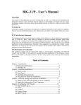
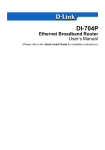
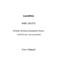
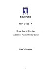
2-Port Wireless Bridge/AP
with Print Server
User Guide
Before operating the unit, please read this manual thoroughly, and retain it for future reference.
FCC Interference Statement
This equipment has been tested and found to comply with the limits for a Class B digital device
pursuant to Part 15 of the FCC Rules. These limits are designed to provide reasonable protection
against radio interference in a commercial environment. This equipment can generate, use and radiate
radio frequency energy and, if not installed and used in accordance with the instructions in this manual,
may cause harmful interference to radio communications. Operation of this equipment in a residential
area is likely to cause interference, in which case the user, at his own expense, will be required to take
whatever measures are necessary to correct the interference.
CE Declaration of Conformity
This equipment complies with the requirements relating to electromagnetic compatibility, EN
55022/A1 Class B, and EN 50082-1. This meets the essential protection requirements of the European
Council Directive 89/336/EEC on the approximation of the laws of the member states relation to
electromagnetic compatibility.
2
Contents
CHAPTER 1 INTRODUCTION ........................................................................1
1.1 Functions and Features ............................................................................................1
1.2 Packing List .............................................................................................................2
CHAPTER 2 HARDWARE INSTALLATION ...................................................3
2.1 Panel Layout ............................................................................................................3
2.2 Procedure of Hardware Installation .........................................................................4
CHAPTER 3 GENERAL CONFIGURATION ...................................................6
3.1 Log in and Start up...................................................................................................6
3.2 Inspect System Information .....................................................................................6
3.3 Tool Box ..................................................................................................................7
3.4 Primary Setup...........................................................................................................8
CHAPTER 4 CONFIGURE AS A BRIDGE....................................................11
4.1 Bridge Configuration .............................................................................................11
4.2 Create a Bridge Network Environment..................................................................12
CHAPTER 5 DHCP SERVER........................................................................13
CHAPTER 6 PRINT SERVER .......................................................................15
6.1 Configuring on Windows 95/98/ME Platforms.....................................................15
6.2 Configuring on Windows 2000/XP Platforms.......................................................17
CHAPTER 7 SOFTWARE INSTALLATION ..................................................18
Appendix A
TCP/IP Configuration for Wireless Windows 95/98/ME/2000/XP.....21
0
Chapter 1 Introduction
Congratulations that you purchase an outstanding Wireless Bridge. This product is
a transceiver that connects two or more remote network into a single LAN and can act
as a center point of a standalone wireless network or as the connection point between
wireless and wired network. This product can also be used as a rugged access point,
providing network access to wireless client devices. It provides a solution for building
a LAN environment and sharing resources with or without wire. This bridge/access
point uses a browser-base management system. The system settings are on web pages.
Before you install and use this product, please read this manual carefully for fully
functions of this product.
1.1 Functions and Features
•
2 in 1 wireless bridge or access point
2-in-1 integrated function, flexibility and cost effective.
•
Point-to-point, Multipoint-to-multipoint connectivity
Lets users transfer information between two or multiple buildings across the
area.
•
Excellent range with antenna options
Provide wireless links up to 25km (16 miles) using antennas and boosters.
•
High speed for wireless LAN connection
11Mbps data rate by incorporating Direct Sequence Spread Spectrum (DSSS).
•
Roaming
Provides seamless roaming within the IEEE 802.11b WLAN infrastructure.
•
IEEE 802.11b compatible
Allowing inter-operation among multiple vendors.
•
Auto fallback
11M, 5M, 2M, 1M data rate with auto fallback.
•
Auto-sensing Ethernet Switch
Equipped with a 2-port auto-sensing Ethernet switch.
•
Printer sharing (Optional)
Embeds a print server to allow all of the networked computers to share one
printer.
1
•
DHCP server supported
All of the networked computers can retrieve TCP/IP settings automatically
from this product.
•
Web-based configuring
Configurable through any networked computer’s web browser.
•
MAC Address Access Control supported
Allows you to assign different access right for different users.
•
Firmware Upgradable
Provides firmware upgrade via Web Browser or Windows Application.
1.2 Packing List
Wireless Bridge/Access Point unit
Installation CD
Power adapter
Cross over Fast Ethernet cable
Rubber Antenna
2
Chapter 2 Hardware Installation
2.1 Panel Layout
2.1.1 Front Panel
Figure 2-1 Front Panel
LED:
LED
Function
POWER Power indication
Color
Status
Green
On
Description
Power is being applied to this
product.
M1
System status 1
Orange
Blinking
This product is functioning
properly.
WLAN
Wireless activity
Green
Blinking
Sending or receiving data via
wireless
Link/Act.
1~2
Link status
10/100
Data Rate
On
An active station is connected to
the corresponding LAN port.
Blinking
The corresponding LAN port is
sending or receiving data.
On
Data is transmitting in 100Mbps
on the corresponding LAN port.
Green
Green
Port:
RESET
To reset system settings to factory defaults, please follow the steps:
1. Power off the device,
2. Press the reset button and hold,
3. Power on the device,
4. Keep the button pressed about 5 seconds,
5. Release the button,
6. Watch the M1 LED, it will flash 8 times and then M1 flash once per
second.
3
2.1.2 Rear Panel
Figure 2-2 Rear Panel
Port
12VDC
Port 1-2
PRINTER
Antenna
Description
Power inlet: DC 12V, 1.5A (minimum)
The ports where you will connect networked computers and other
devices.
Printer Port (Optional)
Connect with antenna (Omni-directional or Directional)
2.2 Procedure of Hardware Installation
1. Decide how to place this product and antenna
Because this product is a radio device works in the 2.4 GHz frequency range.
For optimum utilization, install this product away from microwave ovens or
other devices, operating in the 2.4 GHz frequency range, which can cause
signal interference. Otherwise, install this product’s antenna in an area where
the trees, buildings and large steel structures such as file cabinet and
bookshelves do not obstruct the signal to and from the antenna. The antenna
should be located for the direct line-of-sight space.
2. Connecting the Antenna
This product provides a TNC antenna connector on the rear panel. Use the
proper cable to connect this product and antenna.
3. Setup LAN connection
a. Wired LAN connection: connect an Ethernet cable from your computer’s
Ethernet port to one of the LAN ports on this product’s rear panel.
Repeat the process to connect other computers to this product. If you
need to connect more than two computers to this product, use a 10/100
Fast Ethernet switch (preferred) or hub and connect the Ethernet cable
from the AP to the switch/hub’s UPLINK port. You may need a
switch/hub, which include UPLINK feature. This product supports up to
253 network computers and devices.
b. Wireless LAN connection: locate this product at a proper position to gain
the best transmission performance.
4
Figure 2-3 Setup of LAN connections for this product
Note: If an UPLINK port is not available, simply connect a
cross-over Ethernet cable from the AP to the switch/hub.
4. Connect this Product to the Printer
Use the printer cable to connect the printer to the printer port of this product.
(Optional)
5. Power
Connect the power code to the power outlet and turn on the power switch.
This product will enter the self-testing status automatically. In this phrase, the
indicator M1 will light on for about 10 seconds, and then the M1 will flash 3
times to represent that the self-testing has been finished. Eventually, the M1
indicator will flash once per second to stand for this product is in normal
operation.
5
Chapter 3 General Configuration
3.1 Log in and Start up
This product provides a web based configuration scheme, make possible to
configure by web browser such as Netscape Communicator or Internet Explorer.
1. Start the web browser, and disable the proxy or add the IP address of this
product into the exceptions of Proxy setting. Then, type this product’s IP
address (the default setting is 192.168.123.254) in the Location (for Netscape)
or Address (for IE) field and press ENTER.
2. You will see the web user interface after the connection is established. To log in
as an administrator, enter the system password (the default setting is” admin ”)
in the System Password field and click on the Log in button. If the password is
correct, the web appearance will change to Administrator’s Main Menu.
3.2 Inspect System Information
Check system information with click the System Info in Administrator’s Main
Menu.
A. Network ID (SSID): The current setting of SSID
B. Firmware Version: The current firmware version on this device
C. MAC Address: The MAC address of this device
D. Printer: The possible kinds of printer status include “Ready”, “Not ready”,
“Printing…”, and “Device error”.
Figure 3.1
6
When this device is printing, there may appear a “Kill Job” button on the
Sidenote column. You can click this button to cancel the current printing
job manually.
3.3 Tool Box
This option enables you to change the administrator password.
There are some useful buttons in this page:
View Log
View the system logs
Reboot
Reboot this device
Backup Setting
You can backup your settings by clicking this
button and save it as a bin file. Once you want to
restore these settings, please click Firmware
Upgrade button and use the bin file you saved
Reset to Default
Reset the settings of this device to the default
values
Firmware Upgrade
Prompt the administrator for a file and upgrade it to
this device
Note: we strongly recommend you to change the system password for security
reason.
Figure 3.2
7
3.4 Primary Setup
Figure 3.3
This option is primary to enable this product to work properly.
1.IP Address: the IP address of this device.
2.Mode: the operating mode of this device. The default mode is “Bridge”, which
is the normal operation mode of a Bridge. Users can change it to the “AP”
mode if you want this product to work as a wireless access point.
Figure 3.4
3.Network ID (SSID): Network ID is used for identifying the Wireless LAN
(WLAN). Client stations can roam freely over this product and other Access
Points that have the same Network ID. (The factory setting is “default”).
Note: This item won’t take effect in “Bridge” mode.
4.Channel: The radio channel number. The permissible channels depend on the
Regulatory Domain.
The factory setting is as follows:
Channel 6
USA/Canada
Europe/Australia (ETSI)
Japan (All)
Spain, France
Channel 10
Japan
Channel 14
8
5. WEP Security: Select the data privacy algorithm you want. Enabling the security
can protect your data while it is transferred from one station to another. The
standardized IEEE 802.11 WEP (64-bit or 128-bit) is used here.
6. WEP Key 1, 2, 3 & 4: After enable the 64-bit or 128-bit WEP key security, please
select one WEP key to be used in default setting and then input 10 or 26 hexdecimal (0-9, A-F) digits.
7. MAC Access Control: Setup MAC addresses to control which wireless clients
can associate to the wireless LAN and this device or connect to this device.
Figure 3.5
MAC Address Control allows only client devices with specified MAC
addresses to associate and pass data through this device.
MAC Address Control
Check “Enable” to enable the “MAC Address
Control”. All of the settings in this page will take
effect only when “Enable” is checked.
Connection control
Check "Connection control" to enable the controlling
of which wired and wireless clients can connect to
this device. If a client is denied to connect to this
device, it means the client can't access to the Internet
either. Choose "allow" or "deny" to allow or deny the
clients, whose MAC addresses are not in the "Control
table" (please see below), to connect to this device.
9
Association control
Check "Association control" to enable the controlling
of which wireless client can associate to the wireless
LAN. If a client is denied to associate to the wireless
LAN, it means the client can't send or receive any data
via this device. Choose "allow" or "deny" to allow or
deny the clients, whose MAC addresses are not in the
"Control table", to associate to the wireless LAN.
Control table
"Control table" is the table at the bottom of the "MAC
Address Control" page. Each row of this table
indicates the MAC address and the expected IP
address mapping of a client. There are four columns in
this table:
MAC
Address
IP Address
MAC address indicates a
specific client.
Expected IP address of the
corresponding client. Keep it
empty if you don't care its IP
address.
C
When "Connection control" is
checked, check "C" will
allow/deny the corresponding
client to connect to this device.
A
When "Association control" is
checked, check "A" will
allow/deny the corresponding
client to associate to the
wireless LAN.
In this page, we provide the following Combobox and button to help users to
input the MAC address.
Figure 3.6
Select a specific client in the “DHCP clients” Combobox, and then click on
the “Copy to” button to copy the MAC address of the client you select to the ID
selected in the “ID” Combobox.
Previous page and Next Page To make this setup page simple and clear, we have
divided the “Control table” into several pages.
You can use these buttons to navigate to different
pages.
10
Chapter 4 Configure as a Bridge
Two of these devices have capability to communicate with each other when these
two devices are working in the “Bridge” Mode. Users can connect two or more wired
LANs together via wireless connection with wireless bridge function. The connection
is as follows:
Figure 4.1
Note: This device can’t be a wireless AP when it has been operated as a wireless
bridge. This means there is no wireless client can make the connection to this device
when it’s in the “Bridge” mode.
4.1 Bridge Configuration
1.
2.
3.
4.
Login this device with the administrator’s password as “admin” (default).
Select Primary Setup.
In the Primary Setup page, make sure the Mode is Bridge.
Enter the address into IP Address field which is in the same subnet with your
network environment.
5. Set the “Channel” of this device and another one which you want to connect in
the same channel.
6. Save the settings above and then reboot this device.
11
4.2 Create a Bridge Network Environment
The bridge supports external antennas with omni-directional or directional
capabilities. Omni-directional antennas are suited for systems requiring a signal
distribution in more than one direction. High-gain directional antennas are best suited
for longer coverage range in a fixed direction.
Due to the differences in placement and physical environment, every network
application has their unique installation. Before installing multiple bridges, you
should implement a testing of each site to determine the optimum networking
components and to maximize coverage range and network performance.
Think about the operating and environmental conditions of following when
implement this testing:
•
•
Throughput of Data – Coverage range is inversely proportional to data rates.
The maximum radio range is achieved at the lowest workable data throughput.
Antenna type and placement – The coverage range is increasing by the
antenna’s height and gain. For this reason, proper antenna configuration is a
critical factor in maximizing coverage range. The recommended combination
of antenna/cable/booster for various ranges is as following:
Range
Cable
Antenna gain
(dBi)
Booster
•
4~10km
3/5M 10M
12~18 18
1M
12
None None None 0.5W 0.5W 0.5W
1W
1M
12
3km
3/5M 10M
12~18 18
1M
12
11~18km
3/5M 10M
12~18 18~20
1W
1W
1M
20
1W
19~25km
3/5M 10M
12~21 18~21
5W
Physical environment and Obstructions - Open areas provide better coverage
range than closed areas. Also, the obstructer such as steel buildings or trees
can block or decrease communication between bridges. To avoid this situation,
the antennas should be located in where is no or few obstruction between the
sending and receiving antennas.
Figure 4.2
12
5W
Chapter 5 DHCP Server
Dynamic Host Configuration Protocol (DHCP) is a TCP/IP standard for
simplifying management of host IP configuration. The DHCP standard provides for
the use of DHCP servers as a way to manage dynamic allocation of IP.
Every computer on a TCP/IP network must have a unique computer name and IP
address. The IP address (together with subnet mask) identifies both the host computer
and the subnet to which it is attached. When you move a computer to a different
subnet, the IP address must be changed. DHCP allows you to dynamically assign an
IP address to a client from a DHCP server IP address database on your local network
The settings of a TCP/IP environment of include host IP, Subnet Mask, Gateway,
and DNS configurations. For TCP/IP-based networks, DHCP reduces the complexity
and amount of administrator work involved in reconfiguring computers.
This product supports the function of DHCP server. If you enable this product’s
DHCP server and configure your computers as “automatic IP allocation” mode, then
when your computer is powered on, it will automatically load the proper TCP/IP
settings from this product. The settings of DHCP server include the following items:
1. DHCP Server: Check “Enable” to enable the DHCP server function. All the
settings in this page will take effect only if “Enable” is checked.
2. Range of IP Address Pool: Whenever there is a request, the DHCP server will
automatically allocate an unused IP address from the IP address pool to the
requesting computer. You must specify the starting and ending address of the
IP address pool.
Clients List
List the current mapping of the IP and MAC address for
each DHCP client.
13
Fixed Mapping
In general, DHCP server assigns an IP address chosen
from the IP addresses pool randomly. Fixed Mapping
allows you to assign a specific IP address to the
specified MAC address.
14
Chapter 6 Print Server
This product provides the function of network print server for MS Windows
95/98/NT/2000/XP, Linux and Unix based platforms.
6.1 Configuring on Windows 95/98/ME Platforms
After finished the software installation procedure described in Chapter 7, the
computer has ability to print via this product. For convenience, we call the printer
connected to the printer port of this product as printer server. To configure this printer
server on a Windows 95/98/ME platform, please refer to the following steps.
1. Open the Printers window in the My Computer dialogue window.
2. Find out the corresponding icon of your server printer, for example, the HP
LaserJet 6L. Click the mouse’s right button on that icon, and then select the
Properties item:
15
3. Select the Details item.
4. Choose the “PRTmate: (All-in-1)” from the list attached at the Print To the
following port item. Ensure that the Print using the following driver item is
configured to the correct driver of this printer server.
5. Click Port Settings. Type the IP address of this product and then click the OK
button.
6. Make sure that all settings mentioned above are correct and then click the OK
button.
16
6.2 Configuring on Windows 2000/XP Platforms
The configuration procedure for a Windows 2000/XP platform is similar to that of
Windows 95/98/ME except of the printer Properties.
Compare to the procedure for the setting of windows 95/98/ME, the selection of
Details (windows 95/98/ME) is equivalent to the selection of Ports (windows
2000/XP), and Port Settings (windows 95/98/ME) is equivalent to Configure Port
(windows 2000/XP).
17
Chapter 7 Software Installation
1. Insert the installation CD-ROM into the CD-ROM device. The following
window will be shown automatically. If it isn’t, please run “install.exe” in the
CD-ROM.
2. Click the INSTALL button. Wait until the following Welcome dialogue
appears, and click the Next button.
18
3. Select the destination folder and click the Next button. Then, the setup
program will begin to install this program into the computer.
4. When the following window is displayed, click the Finish button.
5. Select the item to restart the computer and then click the OK button to reboot
your computer.
19
6. After rebooting your computer, you can configure this device (refer to Chapter
4) and setup the Print Server (refer to Chapter 6).
20
Appendix A TCP/IP Configuration for Wireless Windows
95/98/ME/2000/XP
This chapter will introduce how to install the TCP/IP protocol in the personal
computer and using the TCP/IP setting to connect this device correctly.
A.1 Configure Windows 95/98/ME Platforms for working with this
device
1. Connect this device to a computer by general network cable.
2. On the Windows 95/98/ME Platforms, click Start button and choose Settings,
then click Control Panel.
3. Double click Network icon and select Configuration tab in the Network
window.
4. Click Add button to add network component into your PC.
5. Double click Protocol to add TCP/IP protocol.
6. Select Microsoft item in the manufactures list. Then choose TCP/IP in the
21
Network Protocols list. Click OK button to return to Network window.
7. The TCP/IP protocol shall be listed in the Network window. Click OK to
complete the install procedure and restart your PC to enable the TCP/IP
protocol.
8. After rebooting, click Start button and choose Settings, then click Control
Panel.
9. Double click Network icon. Select the TCP/IP line that has been associated to
your network card in the Configuration tab of the Network window.
10. Click Properties button to set the TCP/IP protocol for this device.
11. Select Specify an IP address in the IP Address tab. The default IP address of
22
this product is 192.168.123.254. So please use 192.168.123.xxx (xxx is
between 1 and 253) for IP Address field and 255.255.255.0 for Subnet Mask
field.
12. In the Gateway and DNS tab, do not put anything.
13. Click OK button to finish the TCP/IP setting and restart the computer.
23
A.2 Configure Windows 2000/XP Platforms for working with this
device
1. After complete installation the windows 2000/XP, the system will
automatically install the TCP/IP protocol.
2. Connect this device to a computer by general network cable.
3. On the Windows 2000/XP platform, right click My Network Places on the
desktop then select Properties.
4. In the Network Connections dialogue window, right click the network
connection icon of Wireless LAN PC Card and select properties.
24
5. In the General tab, choose Internet Protocol (TCP/IP) and click the
properties button.
6. In the General tab, select Use the following IP address and set a IP address
which is in the same subnet with this product(default is 192.168.123.254).
7. Do not put anything in the Default gateway and DNS field.
8. Click the OK button to complete TCP/IP setting.
25