1
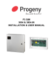
DNCP Solutions, LLC
- A Platinum Equity Company
U522 Ethernet PCI Card
Installation Guide
Part Number: MAN0063-00
Notice
The information contained in this document is subject to change without notice.
UNLESS EXPRESSLY SET FORTH IN A WRITTEN AGREEMENT SIGNED BY AN AUTHORIZED
REPRESENTATIVE OF DNCP SOLUTIONS, LLC. DNCP SOLUTIONS, LLC MAKES NO WARRANTY OR
REPRESENTATION OF ANY KIND WITH RESPECT TO THE INFORMATION CONTAINED HEREIN, INCLUDING
WARRANTY OF MERCHANTABILITY AND FITNESS FOR A PURPOSE. DNCP Solutions, LLC assumes no
responsibility or obligation of any kind for any errors contained herein or in connection with the furnishing, performance,
or use of this document.
This document contains information that is the property of DNCP Solutions, LLC. This document may not be copied,
reproduced, reduced to any electronic medium or machine readable form, or otherwise duplicated, and the information
herein may not be used, disseminated or otherwise disclosed, except with the prior written consent of DNCP Solutions,
LLC.
DNCP, FTX, MultiStack, RSN, SCEnic, and SINAP are trademarks of DNCP Solutions, LLC.
Hewlett-Packard, HP-UX, and all Hewlett-Packard product names in this document are trademarks of Hewlett-Packard
Company.
All other trademarks and registered trademarks are the property of their respective holders.
Manual Name: U522 Ethernet PCI Card Installation Guide
Part Number: MAN0063
Revision Number: 00
Printing Date: September 2002
DNCP Solutions, LLC
55 Fairbanks Boulevard
Marlboro, MA 01752-9899
Copyright © 2002 by DNCP Solutions, LLC.
All Rights Reserved.
Contents
About This Guide
Purpose
Audience
Revision Information
Software Information
How to Use This Guide
Notation and Terminology Conventions
Product Documentation
Related Books
Software
Hardware
A Note on the Contents of DNCP Books
Ordering Documentation
How to Send Comments About This Document
Customer Assistance Center
ix
ix
ix
ix
ix
x
x
xi
xii
xii
xii
xiii
xiii
xiii
xiv
1. Overview
U522 4-Port Ethernet PCI Card
Locating the PCI Cards
Handling PCI Cards
Cabling Specifications
Hardware Requirements
Software Requirements
1-1
1-2
1-3
1-5
1-7
1-7
1-8
2. Installing or Replacing a U522 PCI Card
Installing a U522 PCI Card
Connecting Cables and Configuring the Card
Removing a U522 PCI Card
2-1
2-1
2-6
2-8
3. Troubleshooting
Getting Help
Interpreting the PCI Card Status Lights
Ethernet Network Status Lights
3-1
3-1
3-3
3-5
Contents
iii
Figures
Figure 1-1.
Figure 1-2.
Figure 1-3.
Figure 1-4.
Figure 1-5.
Figure 2-1.
Figure 2-2.
Figure 2-3.
Figure 2-4.
Figure 2-5.
Figure 2-6.
Figure 2-7.
Figure 3-1.
Figure 3-2.
U522 Ethernet PCI Card
PCI Card Cages
Location of PCI Cards
Grounding-Strap Jacks
UTP Cable with the RJ-45 Connector
Installing a U522 Card: Step 1
Installing a U522 Card: Step 3
Installing a U522 Card: Steps 6–8
Connecting Cables and Closing the Card Cage
Removing a U522 PCI Card: Steps 2 and 3
Removing a U522 Card: Steps 5 and 6
Removing a U522 Card: Step 8
PCI Card Status Lights
Ethernet Network Status Lights
1-2
1-3
1-4
1-6
1-7
2-2
2-3
2-5
2-7
2-9
2-11
2-13
3-4
3-6
Figures
v
Tables
Table 3-1.
Table 3-2.
PCI Card Status Lights
Ethernet Network Status Lights
3-3
3-5
Tables
vii
About This Guide
Preface-
Purpose
This guide provides an overview of the U522 PCI (peripheral component interconnect)
card. It also describes how to install or replace the card in a DNCP (Distributed Network
Control Platform) Series 400/400-CO system. The abbreviation CO indicates a Central
Office system.
Audience
This guide is intended for DNCP Solutions customers who are installing or maintaining
a U522 Ethernet PCI card in a DNCP Series 400/400-CO system.
Revision Information
This is the first edition of this document.
Software Information
The U522 PCI card is supported on DNCP Series 400/400-CO systems that run the
HP-UX Operating System. For operating systems prior to HP-UX version 11.00.61, the
U522 card may require that software patches be installed on the operating system. See
the DNCP Patches for U522, U405, U406, D843, and D844 (R300066) document for
the operating system versions and patches required to support the U522 Ethernet PCI
card.
About This Guide
ix
About This Guide
How to Use This Guide
Read...
To Learn About...
Chapter 1
The U522 PCI Card, the location of the cards in the DNCP Series
400/400-CO system, how to handle the cards, cabling
specifications, and hardware and software requirements.
Chapter 2
How to install and replace a U522 PCI Card.
Chapter 3
How to get help and how to interpret PCI Card and Ethernet
network status lights.
Notation and Terminology Conventions
x
Convention
Indicates
Example
Italics
Introduces or defines
terms
This chapter provides an overview of
the U522 PCI card and peripheral
component interconnect cards in
general.
Boldface
Emphasis
Always store the PCI card in its
static-protective envelope if it is not
installed in the system.
Monospace
Commands, functions,
code fragments,
filenames, directories
As long as your system has power,
you can initiate a reboot through the
shutdown or init commands.
CO
Central Office
DNCP Series 400/400-CO systems
provide continuously available
hardware for central office
environments.
U522 Ethernet PCI Card Installation Guide (MAN0063)
About This Guide
Product Documentation
The DNCP Series 400 and 400-CO system documentation is shipped on a DNCP
Series 400/400-CO Documentation CD-ROM containing the following documentation:
• DNCP Series 400 and 400-CO: Site Planning Guide (MAN0050)
• DNCP Series 400 and 400-CO: Attaching and Removing the Caster
Plates (MAN0051)
• DNCP Series 400 and 400-CO: D859 CD-ROM Drive: Installation and Operation
Guide (MAN0052)
• DNCP Series 400 and 400-CO: T807/T808 Tape Drive Release Notes (MAN0053)
• DNCP Series 400 and 400-CO: D84X Disk Drive Release Notes (MAN0054)
• DNCP Series 400 and 400-CO: Tape Drive Installation and Operation
Guide (MAN0055)
• DNCP Series 400 and 400-CO: Operation and Maintenance Guide (MAN0056)
• DNCP Series 400 and 400-CO: PA-8600 Suitcase Replacement and Upgrade
Guide (MAN0057)
• U406 Synchronous PCI Card Installation Guide (MAN0058)
• U450 Asynchronous PCI Card Installation Guide (MAN0059)
• U501 SCSI PCI Card Installation Guide (MAN0060)
• U512 Ethernet PCI Card Installation Guide (MAN0061)
• U522 Ethernet PCI Card Installation Guide (MAN0063)
• U916 T1/E1 PCI Card Installation Guide (MAN0064)
About This Guide
xi
About This Guide
Related Books
In addition to this document, the following documentation contains information related
to the DNCP fault-tolerant platforms and supported operating systems:
Software
• DNCP Patches for U522, U405, U406, D843, and D844 (R300066)
• HP-UX Operating System: Fault Tolerant System Administration (MAN0004)
• HP-UX Operating System: Read Me Before Installing (MAN0003)
• HP-UX Operating System: LAN Configuration Guide (MAN0005)
• HP-UX Operating System: Redundant Network Interface (MAN0006)
• HP-UX Operating System: Peripherals Configuration (MAN0001)
• HP-UX Operating System: Installation and Update (MAN0002)
• HP-UX Operating System: Remote STREAMS Release Notes and Installation
Instructions (R1013H)
Hardware
• DNCP Series 400 and 400-CO: Site Planning Guide (MAN0050)
• DNCP Series 400 and 400-CO: Operation and Maintenance Guide (MAN0056)
• U450 Asynchronous PCI Card Installation Guide (MAN0059)
• U501 SCSI PCI Card Installation Guide (MAN0060)
• U512 Ethernet PCI Card Installation Guide (MAN0061)
• U513 Ethernet PCI-Card Installation Guide (MAN0062)
• U916 T1/E1 PCI Card Installation Guide (MAN0064)
xii
U522 Ethernet PCI Card Installation Guide (MAN0063)
About This Guide
A Note on the Contents of DNCP Books
DNCP books document all of the subroutines and commands of the user interface. Any
other commands and subroutines contained in the operating system are intended
solely for use by DNCP Solutions personnel and are subject to change without warning.
Ordering Documentation
You can order additional manuals or documentation CD-ROMs in either of the following
ways:
• If your system is connected to the Remote Service Network (RSN), add a call using
the Site Call System (SCS). See the scsac(1) man page for more information.
• Call the Customer Assistance Center (see ‘‘Customer Assistance Center”). Your
order will be forwarded to Order Administration.
You can also download manuals from the DNCP Solutions Patch Manager web site at
http://pman3.com/pman. You will need your Site ID and password to access this
site.
How to Send Comments About This Document
If you have comments about this document, you can fill out and mail the postage-paid
response card at the back of this document.
We welcome any corrections and suggestions for improving this document.
About This Guide
xiii
About This Guide
Customer Assistance Center
You may contact the DNCP Solutions Customer Assistance Center (CAC), 24 hours a
day, 7 days a week by calling one of the phone numbers listed below.
xiv
Service Area
CAC Location
Phone Number
North and South
America
Scottsdale, Arizona
USA
800-404-1561 (within North America)
480-391-8561 (outside North America)
EMEA (Europe,
Middle East and
Africa)
Sophia Antipolis, France
+33-492-386-208
Greater China
Hong Kong, China
+852-8202-2562
Asia / Pacific
Tokyo, Japan
0120-787287 (within Japan)
81-3-3589-6034 (outside Japan)
U522 Ethernet PCI Card Installation Guide (MAN0063)
Chapter 1
Overview
1-
This chapter provides an overview of the U522 PCI card and peripheral component
interconnect (PCI) cards in general. This chapter includes:
• Locating the PCI Cards
• Handling PCI Cards
• Cabling Specifications
• Hardware Requirements
• Software Requirements
Overview
1-1
U522 4-Port Ethernet PCI Card
U522 4-Port Ethernet PCI Card
The U522 PCI card is a high-performance 4-Port Ethernet adapter that enables you to
connect a DNCP Series 400/400-CO system to a local area network (LAN). The U522
PCI card is based on a 32-bit bus architecture that optimizes data flow between the
system and the network, resulting in the highest possible throughput with low CPU
utilization.
The U522 PCI card provides both 10 megabits-per-second (Mbps) Regular Ethernet
and 100-Mbps Fast Ethernet communication. The card automatically senses the speed
of the port to which it is attached, and configures itself accordingly.
Each DNCP Series 400/400-CO system can support up to four U522 PCI cards (16
LAN ports). These cards can be paired, using the Redundant Network Interface (RNI),
to provide backup fail-over protection. Figure 1-1 shows the U522 PCI card.
Figure 1-1. U522 Ethernet PCI Card
1-2
U522 Ethernet PCI Card Installation Guide (MAN0063)
Locating the PCI Cards
Locating the PCI Cards
The PCI cards in a DNCP Series 400/400-CO system are installed in one of two PCI
card cages, located at the rear of the cabinet (Figure 1-2).
PCI Card Cages
Card
Cage 2
Rear of
System
Card
Cage 3
cp0145
Figure 1-2. PCI Card Cages
Overview
1-3
Locating the PCI Cards
Figure 1-3 shows the location of the PCI cards in the PCI card cages. The U522 card
can be installed in any of the “optional PCI card” slots.
Rear of
System
SCSI
PCI Card
PCI
Bridge Card
PCI
Status
Lights
Card Cage
Slot Labels
Optional
PCI
Cards
7
Red
Yellow
Green
6
SCSI
PCI Card
Optional
PCI
Cards
PCI
Bridge Card
Optional
PCI
Cards
5
4
0
3
2
Optional
PCI
Cards
1
7
6
5
4
0
3
2
1
PCI Card
Cage 2
PCI Card
Cage 3
cp0146
Figure 1-3. Location of PCI Cards
1-4
U522 Ethernet PCI Card Installation Guide (MAN0063)
Handling PCI Cards
Handling PCI Cards
PCI cards are extremely sensitive to electrostatic discharge. To avoid damaging a PCI
card during handling, take the following precautions.
CAUTION
Do not walk around carrying a PCI card that is not in its
static-protective envelope, as it can damage the card.
• Always store the PCI card in its static-protective envelope if it is not installed
in the system.
• Always hold a PCI card by its edges.
• Always ground yourself before handling a PCI card. To ground yourself, touch
the inside of the PCI card cage to discharge any static electricity, or wear a
grounding strap. If you have a grounding strap, attach one end to the rear of
the system, and place the other around your wrist (Figure 1-4).
Overview
1-5
Handling PCI Cards
Figure 1-4 shows the location of the grounding-strap jacks on the 400-CO system.
Grounding-Strap
Jack
Rear of System
cp0254
Figure 1-4. Grounding-Strap Jacks
1-6
U522 Ethernet PCI Card Installation Guide (MAN0063)
Cabling Specifications
Cabling Specifications
The U522 PCI card uses unshielded twisted-pair (UTP) Category 5 Data Grade cable
with an RJ-45 connector. The maximum length of the cable from the U522 PCI card to
the concentrator or switch cannot exceed 100 meters.
Figure 1-5 shows the UTP cable with the RJ-45 connector.
ux0056
Figure 1-5. UTP Cable with the RJ-45 Connector
Hardware Requirements
Depending on how the card will be used, one or more of the following must be installed
or available at your site.
• DNCP Series 400/400-CO system
• RJ-45 Connector
• UTP Category 5 Data Grade cable
Overview
1-7
Software Requirements
Software Requirements
For operating systems prior to HP-UX version 11.00.61, the U522 card may require that
software patches be installed on the operating system. See the DNCP Patches for
U522, U405, U406, D843, and D844 (R300066) document for the HP-UX operating
systems and software patches needed to support the U522 PCI card on the DNCP
platform.
Also, the required Ethernet communications software must be installed before you can
use the U522 card. For information about installing and configuring the
communications software to be used with the U522 card, refer to the following:
• HP-UX Operating System: LAN Configuration Guide (MAN0005)
• HP-UX Operating System: Redundant Network Interface (MAN0006)
CAUTION
Do not use the RNI to pair two cards in the same card
cage. If you pair two cards in the same card cage, loss of
power to that card cage (including opening the card cage
door) will terminate the network link.
CAUTION
Do not use the RNI to pair two LAN ports on a single U522
PCI card.
1-8
U522 Ethernet PCI Card Installation Guide (MAN0063)
Installing or Replacing a U522 PCI Card
Chapter 2
Installing or Replacing a U522
PCI Card
2-
Installing a U522 PCI Card
Before installing and using a U522 card, make sure the appropriate communications
software is installed and configured at your site.
CAUTION
Opening a card cage door stops the data communications
associated with any simplexed cards in that card cage.
Before you open the card cage door, determine what
resources will be affected.
1. Open the door of the PCI card cage (Figure 2-1). When you open the door, the
power to that card cage is suspended.
2. Identify the slot into which you intend to install the PCI card.
Installing or Replacing a U522 PCI Card
2-1
Installing a U522 PCI Card
Rear of
System
cp0181
Figure 2-1. Installing a U522 Card: Step 1
2-2
U522 Ethernet PCI Card Installation Guide (MAN0063)
Installing a U522 PCI Card
3. Loosen the thumbscrews and open the retainer bar that secures the filler panel to
the card cage frame for this slot. Then remove the filler panel (Figure 2-2).
Retainer Bar
Filler
Panel
Rear of
System
cp0182
Figure 2-2. Installing a U522 Card: Step 3
Installing or Replacing a U522 PCI Card
2-3
Installing a U522 PCI Card
4. Touch the side of the PCI card cage to discharge any static electricity.
CAUTION
To avoid damaging the PCI card, leave the card in its
static-protective envelope until you are ready to install it.
When you remove the card, hold it by its edges.
5. Remove the U522 card from its static-protective envelope.
6. Align the PCI card with the appropriate slot in the card cage frame and with the
backplane connector (Figure 2-3).
7. Press the PCI card gently but firmly into the backplane connector.
8. Close the retainer bar that secures the PCI card to the card cage frame and tighten
the thumbscrews.
2-4
U522 Ethernet PCI Card Installation Guide (MAN0063)
Installing a U522 PCI Card
6
Card
Slot
7
Backplane
Connector
8
Retainer Bar
cp0283
Figure 2-3. Installing a U522 Card: Steps 6–8
Installing or Replacing a U522 PCI Card
2-5
Installing a U522 PCI Card
Connecting Cables and Configuring the Card
After installing the U522 card in the PCI card cage, you must connect the UTP cables
to the card and, if necessary, configure the card.
1. Connect the UTP cables to the card connectors on the top of the PCI card cage
(Figure 2-4).
2. Close the card cage door. When you close the door, power is restored to the card
cage.
3. If you replaced a U522 card that had been previously installed in the same slot, the
card performs a self-test, during which the yellow status light on the card cage is
illuminated. The yellow light then flashes while the system configures the card.
When the card is online, both the green and the yellow lights are illuminated,
indicating the card is running simplexed.
If this is a first-time installation, the red status light is illuminated, indicating that you
must install the communications software and configure it for use with the U522
card. Refer to the appropriate manual from those listed in the ‘‘Software
Requirements’’ in Chapter 1 for information on these procedures.
2-6
U522 Ethernet PCI Card Installation Guide (MAN0063)
Installing a U522 PCI Card
1
2
3
Rear of System
Red
Yellow
Green
cp0325
Figure 2-4. Connecting Cables and Closing the Card Cage
Installing or Replacing a U522 PCI Card
2-7
Removing a U522 PCI Card
Removing a U522 PCI Card
CAUTION
When handling a PCI card, always ground yourself to
prevent electrostatic discharge from damaging the card.
In addition, always hold the card by its edges; never touch
the components on the card.
1. Check to see whether the red indicator light is illuminated. If it is, do not remove the
card from service without consulting your local DNCP Solutions Customer
Assistance Center. See ‘‘Getting Help” in Chapter 3. Otherwise, proceed to the
step.
2. Stop any processes or software that are using the U522 PCI card. If remote users
are connected through the card, ask them to log off, as disconnecting the card will
remove the system from the network.
3. Disconnect the cable or cables from the PCI card by squeezing the side of the
cable connector and gently pulling it out of the PCI card (Figure 2-5).
4. Disable the PCI card. Refer to HP-UX Operating System: Fault Tolerant System
Administration (MAN0004) for disabling instructions.
CAUTION
Opening a card cage door stops the communications
associated with any simplexed cards in that card cage.
Before you open the card cage door, determine what
resources will be affected.
5. Open the door of the PCI card cage (Figure 2-5). When you open the door, the
power to that card cage is suspended.
2-8
U522 Ethernet PCI Card Installation Guide (MAN0063)
Removing a U522 PCI Card
4
5
Rear of System
Figure 2-5. Removing a U522 PCI Card: Steps 2 and 3
Installing or Replacing a U522 PCI Card
2-9
Removing a U522 PCI Card
6. Identify the slot from which you intend to remove the PCI card.
NOTE
Due to the heat generated when the system is running, a
PCI card may feel warm when you remove it. The PCI card
will cool if you wait for two minutes after opening the card
cage door before you remove the card.
7. Loosen the thumbscrews and open the retainer bar that secures the card to the
frame of the PCI card cage (Figure 2-6).
8. Grasp the top of the card with both hands (remember not to touch the components
on the card). Pull one end of the card outward to loosen it from the backplane
connector, then pull the other end outward to remove the card from the connector.
When the card is free, gently pull it out of the card cage.
2-10
U522 Ethernet PCI Card Installation Guide (MAN0063)
Removing a U522 PCI Card
Retainer Bar
7
8
cp0284
Figure 2-6. Removing a U522 Card: Steps 5 and 6
Installing or Replacing a U522 PCI Card
2-11
Removing a U522 PCI Card
CAUTION
To avoid damaging the PCI card, store it in a
static-protective envelope.
9. Store the PCI card in a static-protective envelope. If you are replacing the PCI card
with a new card, see the ‘‘Installing a U522 PCI Card” section in this chapter now.
If not, see step 8.
10. Install the filler panel that covers the opening in the rear of the card cage frame.
Then, close the retainer bar that secures the PCI card to the card cage frame and
tighten the thumbscrews (Figure 2-7).
11. Enable the PCI card. See HP-UX Operating System: Fault Tolerant System
Administration (MAN0004) for more information.
12. Close the card cage door. When you close the door, power is restored to the card
cage.
2-12
U522 Ethernet PCI Card Installation Guide (MAN0063)
Removing a U522 PCI Card
Filler
Panel
10
Retainer Bar
cp0187
Figure 2-7. Removing a U522 Card: Step 8
Installing or Replacing a U522 PCI Card
2-13
Chapter 3
Troubleshooting
3-
DNCP Solutions maintenance software continuously monitors the function of PCI
cards. If a PCI card malfunctions, the system determines the severity of the problem.
If a malfunction is transient, the PCI card restarts automatically. If a malfunction is
permanent, the system takes the card out of service and the red status light on the PCI
card cage is illuminated.
In addition, the system records all PCI malfunctions in the online system error log files
and displays corresponding error messages on the system console. HP-UX error log
files use the path name /var/adm/syslog/syslog.log
Getting Help
DNCP Solutions systems offer a unique failure-reporting and remote diagnosis feature
known as the Remote Service Network (RSN). If the RSN is connected to your system,
it automatically reports all part failures to the DNCP Solutions Customer Assistance
Center (CAC), which then notifies you of the problem and diagnoses its cause. (If you
are serviced by a distributor, the remote diagnosis and service process may vary.) If
the problem is caused by a failed PCI card, the CAC provides you with a replacement
procedure.
You may contact the DNCP Solutions Customer Assistance Center (CAC), 24 hours a
day, 7 days a week by calling one of the phone numbers listed below.
Service Area
CAC Location
Phone Number
North and South
America
Scottsdale, Arizona
USA
800-404-1561 (within North America)
480-391-8561 (outside North America)
EMEA (Europe,
Middle East and
Africa)
Sophia Antipolis, France
+33-492-386-208
Greater China
Hong Kong, China
+852-8202-2562
Asia / Pacific
Tokyo, Japan
0120-787287 (within Japan)
81-3-3589-6034 (outside Japan)
Troubleshooting
3-1
Getting Help
DNCP Solutions does not expect you to diagnose complex problems or perform major
repairs. However, in some cases you may be able to solve a problem without replacing
the card or contacting the CAC. When a status light or console message suggests that
either a U522 PCI card has failed or there is a network problem, follow these steps.
1. Check the syslog.log file, which may provide more detailed information about
the problem.
2. If the CAC has not contacted you, notify the CAC of the card failure. The CAC will
verify your diagnosis.
NOTE
By helping you perform online diagnostic tests, the CAC
may be able to assist you in fixing a PCI card related
problem without replacing the PCI card.
3. If the CAC advises you to replace a PCI card, see “Chapter 2, ‘‘Installing or
Replacing a U522 PCI Card,” for the replacement procedures.
3-2
U522 Ethernet PCI Card Installation Guide (MAN0063)
Interpreting the PCI Card Status Lights
Interpreting the PCI Card Status Lights
Each PCI card has three status lights that are arranged in a traffic light configuration
directly above the card on the PCI card cage. These status lights indicate the current
condition of the card. Figure 3-1 shows the status lights, and Table 3-1 explains their
meaning. A status light sticker is attached below the PCI card doors, in the rear of the
cabinet, for easy reference.
Table 3-1. PCI Card Status Lights
Light
State
Meaning
Action
Red
Yellow
Green
On
Off
Off
The PCI card has
failed.
Do not remove the card from service
without consulting the CAC. See the
‘‘Getting Help” section in this chapter.
Red
Yellow
Green
Off
On
On
The PCI card is
functioning correctly.
No action is required.
Red
Yellow
Green
On
Off
On
Ethernet ports are not
functioning correctly.
See the ‘‘Getting Help” section in this
chapter. Do not open the card cage door or
remove the cable for this card. Either action
will stop the data communications
associated with this PCI card.
Red
Yellow
Green
On
On
On
One of the PCI card’s
Ethernet ports is not
functioning correctly.
See the ‘‘Getting Help” section in this
chapter. Do not open the card cage door or
remove the cable for this card. Either action
will stop the data communications
associated with this PCI card.
Troubleshooting
3-3
Interpreting the PCI Card Status Lights
PCI
Card Cage 2
Status Lights
PCI
Card Cage 3
Status Lights
Red
Yellow
Green
Rear of
System
cp0147
Figure 3-1. PCI Card Status Lights
3-4
U522 Ethernet PCI Card Installation Guide (MAN0063)
Ethernet Network Status Lights
Ethernet Network Status Lights
In addition to the status lights on the PCI card cage, there are eight status lights located
on the U522 PCI card itself. These status lights show activity on the Ethernet network.
There is a pair of green and yellow lights above and below the four RJ-45 cable
connectors. The yellow LNK (link) light indicates the card is connected to the network
and is receiving link pulses. The green ACT (activity) light indicates activity on the
network.
Figure 3-2 shows the Ethernet-network status lights on the U522 PCI card, and
Table 3-2 explains their meaning.
Table 3-2. Ethernet Network Status Lights
Lights
State
Meaning
Green
Yellow
On
On
The U522 PCI card is operating normally. The network is operational.
Green
Yellow
On
Off
The U522 PCI card is operational, but is not transmitting or receiving
data. Either the network is idle or the network driver is not loaded.
Green
Yellow
Off
Off
There is a network failure. Either the power to the card is off, the card
has been disconnected from the network, the diagnostics have failed,
or the card is a standby.
Troubleshooting
3-5
Ethernet Network Status Lights
CH1
(Port 4)
CH2
(Port 5)
CH3
(Port 6)
CH4
(Port 7)
Figure 3-2. Ethernet Network Status Lights
3-6
U522 Ethernet PCI Card Installation Guide (MAN0063)
Status Lights
LNK (Green)
ACT (Yellow)
U522 Ethernet PCI Card Installation Guide
(MAN0063)
Customer Survey
We value your comments...
Our goal is to continuously improve the quality of our documentation. You can help us achieve this goal by taking
a few minutes to complete this survey.
1
Please rate the quality of this manual in each of the following areas.
Strongly
Agree
Neutral
Disagree
Strongly
Disagree
Technical Accuracy
The product works as described in the manual.
Completeness
The information is complete.
Clarity
The information is easy to understand.
Organization
The information is easy to find.
Figures
The figures are clear and useful.
Examples
The examples are clear and useful.
Index
The topics lead to the information that you need.
Physical Appearance
The format of the manual enhances readability.
Effectiveness
The manual helped you to perform your job.
Fold
Cut along dotted line.
Agree
2
What did you like most about this manual? _____________________________________________________
_______________________________________________________________________________________
3
What did you like least about this manual?_____________________________________________________
_______________________________________________________________________________________
4
Fold
5
6
Is there any information that you would like to have added to this manual? If so, where would it be most helpful?
New information that you would like to have added
Location
____________________________________________________
___________________
____________________________________________________
___________________
Would you like to see more examples in this manual? If so, where would they be most helpful?
New examples that you would like to have added
Location
____________________________________________________
___________________
____________________________________________________
___________________
Did you find errors in this manual? If so, please note the problem(s) and the location in the manual.
Any inaccuracies that you found in this manual
Location (page/paragraph)
____________________________________________________
___________________
____________________________________________________
___________________
Customer Survey
MAN0063-00
7
Do you have any other comments or suggestions? ___________________________________________________
___________________________________________________________________________________________
8
Would you please complete the following information so that we may better understand who reads our manuals?
Name: ____________________
Title: ____________________
Company: _________________________
Mailing Address: ____________________________________________________________________________
What is your level of expertise with this product? ____________________________________________________
What tasks do you perform using this product? _____________________________________________________
Would you be willing to talk to us about your comments?
Yes
No
If yes, what is your phone number and when is a good time to call you? ___________________________________
Fold
Thank you for your help.
BUSINESS REPLY MAIL
FIRST CLASS
MAIL PERMIT NO. 86
MARLBORO, MA
Postage will be paid by addressee:
DNCP Solutions, LLC
c/o DNCP Publications
55 Fairbanks Boulevard
Marlboro, MA 01752-9899
Cut along dotted line.
NO POSTAGE
NECESSARY
IF MAILED
IN THE
UNITED STATES
Fold
DNCP Solutions, LLC
55 Fairbanks Boulevard
Marlboro, MA 01752-9899
9