1
PID Network
Interface Module for
RelianceTM Shark PLC
7 May 2002
MAN0003-04
Page iii
LIMITED WARRANTY AND LIMITATION OF LIABILITY
Horner APG, LLC., ("HE") warrants to the original purchaser that the PID Network Module
manufactured by HE is free from defects in material and workmanship under normal use and
service. The obligation of HE under this warranty shall be limited to the repair or exchange of any
part or parts which may prove defective under normal use and service within two years from the
date of manufacture or eighteen (18) months from the date of installation by the original purchaser,
which ever occurs first. Such defect to be disclosed to the satisfaction of HE after examination by
HE APG of the allegedly defective part or parts. THIS WARRANTY IS EXPRESSLY IN LIEU OF
ALL OTHER WARRANTIES EXPRESSED OR IMPLIED INCLUDING THE WARRANTIES OF
MERCHANTABILITY AND FITNESS FOR USE AND OF ALL OTHER OBLIGATIONS OR
LIABILITIES AND HE APG NEITHER ASSUMES, NOR AUTHORIZES ANY OTHER PERSON
TO ASSUME FOR HE, ANY OTHER LIABILITY IN CONNECTION WITH THE SALE OF THIS PID
NETWORK MODULE. THIS WARRANTY SHALL NOT APPLY TO THIS PID NETWORK
MODULE OR ANY PART THEREOF WHICH HAS BEEN SUBJECT TO ACCIDENT, NEGLIGENCE, ALTERATION, ABUSE, OR MISUSE. HE APG MAKES NO WARRANTY WHATSOEVER IN RESPECT TO ACCESSORIES OR PARTS NOT SUPPLIED BY HE. THE TERM
"ORIGINAL PURCHASER", AS USED IN THIS WARRANTY, SHALL BE DEEMED TO MEAN
THAT PERSON FOR WHOM THE PID NETWORK MODULE IS ORIGINALLY INSTALLED. THIS
WARRANTY SHALL APPLY ONLY WITHIN THE BOUNDARIES OF THE CONTINENTAL
UNITED STATES.
In no event, whether as a result of breach of contract, warranty, tort (including negligence) or
otherwise, shall HE APG or its suppliers be liable for any special, consequential, incidental or
penal damages including, but not limited to, loss of profit or revenues, loss of use of the products
or any associated equipment, damage to associated equipment, cost of capital, cost of substitute
products, facilities, services or replacement power, down time costs, or claims of original
purchaser's customers for such damages.
To obtain warranty service, return the product to your distributor after obtaining a "Return Material
Authorization" (RMA) number. Send the module with a description of the problem, proof of
purchase, post paid, insured, in a suitable package.
Page iv
TABLE OF CONTENTS
PREFACE .
.
.
.
.
ABOUT THE PROGRAMMING EXAMPLES
COPYRIGHT NOTICE
.
.
.
TRADEMARK ACKNOWLEDGMENTS .
.
.
.
.
.
.
.
.
.
.
.
.
vi
vi
vi
vi
.
.
.
.
.
.
.
.
.
.
.
.
.
.
.
.
.
.
.
.
Page 1-1
Page 1-1
.
Page 1-1
Page 1-2
Page 1-2
.
.
.
.
.
.
.
.
Page 2-1
Page 2-1
What is a "Recipe"? .
.
.
.
.
What is a "Job"?
.
.
.
.
.
PID Parameter Information Flow .
.
.
Starting the Recipe Editor Software
.
.
The Status Bar
.
.
.
.
.
Accessing Commands Using the Pull-Down Menus
.
.
.
.
.
.
Page 3-1
Page 3-2
Page 3-2
.
Page 3-4
Page 3-4
Page 3-4
3.6.1
3.6.2
3.6.3
3.6.4
CHAPTER 1:INTRODUCTION
1.1
1.2
1.3
1.4
1.5
Manual Convention .
What You Have
.
What Else You Need
System Features .
Hardware Description
CHAPTER 2:INSTALLATION
2.1
2.2
Module Placement .
Terminal Wiring
.
CHAPTER 3:THE RECIPE EDITOR SOFTWARE
3.1
3.2
3.3
3.4
3.5
3.6
The File Menu
.
The Recipe Menu .
The Job Number Menu
The Change Menu .
.
.
.
.
.
.
.
.
.
.
.
.
.
.
.
.
Page 3-4
Page 3-5
Page 3-6
Page 3-6
Commands Initiated by the PLC .
NIM I/O Reference Usage .
.
.
.
.
.
.
.
Page 4-1
Page 4-1
CHAPTER 4:AUTOMATIC MODE
4.1
4.2
Page v
4.3
4.4
NIM I/O Reference Definitions
Executing PLC Commands.
.
.
.
.
.
.
.
.
Page 4-1
Page 4-3
RECIPE DOWNLOAD
.
JOB DOWNLOAD .
.
MONITOR PID
.
.
DOWNLOAD PID SETPOINT
.
.
.
.
.
.
.
.
.
.
.
.
.
.
.
.
Page 4-4
Page 4-5
Page 4-6
Page 4-7
Page vi
PREFACE
This manual explains how to use the Horner APG PID Network Module which interfaces with
the Reliance Shark PLCs. This manual describes the operation of the 45C-PIDNET when used
in conjunction with the stand alone PID controllers .
ABOUT THE PROGRAMMING EXAMPLES
The example programs and program segments in this manual are included solely for illustrative
purposes. Due to the many variables and requirements associated with any particular
installation, Horner APG cannot assume responsiblity or liability for actual use based on the
examples and diagrams. It is the sole responsibility of the system designer utilizing the PID
Network Module to appropriately design the end system, to appropriately integrate the PID
Network Module and to make safety provisions for the end equipment as is usual and customary
in industrial applications as defined in any codes or standards which apply.
COPYRIGHT NOTICE
Copyright (c) 2002, Horner APG, LLC., 640 N. Sherman Drive, Indianapolis, IN 462013899. All rights reserved. No part of this publication may be reproduced, transmitted,
transcribed, stored in a retrieval system, or translated into any language or computer language,
in any form by any means, electronic, mechanical, magnetic, optical, chemical, manual or
otherwise, without prior agreement and written permission of Horner APG, LLC.
Information in this document is subject to change without notice and does not represent a
commitment on the part of Horner APG, LLC Inc.
TRADEMARK ACKNOWLEDGMENTS
Reliance is a trademark of Reliance Industrial Control.
CHAPTER 1: INTRODUCTION
Page 1-1
CHAPTER 1: INTRODUCTION
The PID Network Interface Module (NIM) allows for the seamless integration of stand-alone PID
controllers with the Reliance Shark PLC. The module interfaces via RS-485 with up to 28 PID
controllers. These controllers feature a wide variety of input and output configurations. The
operation of these controllers is described in detail in the HE Stand Alone PID Controller User
Manual. The "stand-alone" nature of these controllers allow many PID loops to be integrated with
a single Shark PLC without significantly increasing the scan time of the PLC system. The
controllers also can continue to operate normally whether or not the PLC is operational.
1.1
Manual Convention
In this manual, the Network Interface Module will be referred to as an NIM. The stand-alone PID
controllers will be referenced as PIDs. These abbreviations will be made for both clarity and brevity
of the instructions contained in this manual.
1.2
What You Have
The HE Network Interface Module (NIM) comes complete with the
following items:
1.3
A.
Network Interface Module (NIM),
B.
Recipe Editor Software,
C.
This Manual.
What Else You Need
A complete HE PID Network also requires the following:
A.
An IBM compatible computer running DOS 2.0 or later with at least one serial
(COM) port. The COM port must be interrupt based. Almost all personal
computers utilize interrupt based serial ports.
Page 1-2
1.4
CHAPTER 1: INTRODUCTION
B.
A Serial Cable to connect a personal computer to the NIM RS-232
serial port.
C.
One or more HE stand-alone PID Controllers (PIDs)
and the associated user's manual.
D.
Shielded, twisted-pair wiring for connection between the NIM
and the PIDs.
System Features
The HE Network Interface Module (NIM) features:
o
The ability to communicate with up to 28 HE stand-alone PID
controllers via RS-485,
o
PID parameters set-up with personal computer software,
o
Stores up to 41 sets of PID parameters ("recipes"),
o
Stores up to 51 lists of controllers and recipes ("jobs") which can be downloaded
automatically for easy production line changeover,
o
Updates the PLC with the latest process and control variable values for each
controller.
1.5
Hardware Description
The HE Network Interface Module (NIM) features an 80C51 microprocessor running at 11.052
MHz. It incorporates two serial ports. The RS-232 port is used for setup purposes and operates
at 9600 baud, no parity, eight data bits and one stop bit. The RS-485 port is used for network
communications with the PID controllers (PIDs) and operates at 2400 baud, no parity, eight data
bits, and one stop bit.
CHAPTER 2: INSTALLATION
Page 2-1
CHAPTER 2: INSTALLATION
2.1
Module Placement
The Horner Electric PID Network Interface Module (NIM) may be placed in any Reliance Shark
PLC slot. Follow the instructions in your Reliance manual for module insertion and removal.
2.2
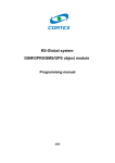
Terminal Wiring
The Network Interface Module features two (2) serial communications port. The RS-232
(programming) port has a DB-9, 9-pin female connector. The cable diagrams in Figure 2-1 can
be used to construct a serial cable for communications between the port and a personal
computer.
NIM
COMPUTER (AT)
DB9M
DB9F
2
3
5
7
8
2
3
5
7
8
Figure 2-1
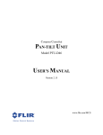
The RS-485 (network) port has a DB-15, 15-pin female connector. Only three wires are required
for communications between the NIM and the PID controllers. The wiring diagram in Figure 22 illustrates proper cable construction for network communications. Note the terminating
resistor that must be added to the terminal strip of the last PID controller on the daisy chained
network
NIM
DB15M
120Ω
Ω
(internal)
PID CONTROLLER
SCREW TERMINAL
9
10
B
11
A
1
COM
Figure 2-2
120Ω
Ω
(user supplied, end
unit only)
Page 3-1
CHAPTER 3: THE RECIPE EDITOR SOFTWARE
CHAPTER 3: THE RECIPE EDITOR SOFTWARE
The Network Interface Module (NIM) serves two purposes in the PID network. First, it provides
an interface between the PID controllers (PIDs) and the Reliance Shark PLC. This interface
allows the PLC to receive updates on the current status of control variables and process
variables in individual PID controllers. Second, it stores within its memory PID parameter
recipes and jobs. These can be downloaded to the PIDs upon command from the PLC.
The NIM operates under two “modes” of operation, Manual and Automatic. In Automatic
Mode, the NIM receives its instructions from the PLC. This is the normal mode of operation
after a PID network has been installed and is controlling the process. Before this can happen,
recipes and jobs should be created and stored in the NIM. Manual Mode, discussed here,
typically is the mode of operation during the setup of the NIM, when it receives its commands
from the Recipe Editor software.
3.1
What is a “Recipe”?
A recipe is a complete set of PID parameters stored in the NIM which may be downloaded on
demand to one or more PID controller(s). PID parameters stored in the recipe are described
in detail in the HE Stand-Alone PID Controllers User’s Manual, and include the
following:
CONTROLLER TYPE
SETPOINT
GAIN OUTPUT
GAIN RATIO OUTPUT
PID RATE
PID RESET TIME
CYCLE TIME PID OUTPUT 1
CYCLE TIME PID OUTPUT 2*
RAMP-TO-SETPOINT TARGET TIME
LOWER SETPOINT LIMIT
UPPER SETPOINT LIMIT
* applies only to PIDs with two outputs.
Up to 41 different recipes can be stored in the NIM. Each recipe must have a unique number,
between 0 and 40 inclusive. Each PID may use several different recipes. Also, one recipe
may be shared by several different PIDs. The only restriction is that a recipe can only be
shared by PIDs of identical type (i.e. same type of inputs and outputs). Figure 3-1 shows a
sample recipe as stored in the NIM.
CHAPTER 3: THE RECIPE EDITOR SOFTWARE
Page 3-2
Figure 3-1
3.2
What is a “Job”?
In manufacturing operations, a single production line may produce many different products.
The process of adjusting or modifying a production line to run a different product is often called
“changeover”. When using PIDs on a production line, changing parameters or recipes is a
common way in which the PIDs can be “changed over” to produce a different product.
A “job” is a list of PIDs with specified recipe numbers which are to be used in a given production line setup. When a production line changeover to a new job is instigated by the PLC, the
NIM downloads new recipes to the PIDs based on the information stored in the job list. Figure
3-2 shows a sample job as stored in the NIM.
If a production line produces many different products, a unique “job” may be stored for each
product. If a production line produces only one product, it is likely that only one job will be
used. Up to 51 different jobs, numbered 0 to 50, may be stored in the NIM.
3.3
PID Parameter Information Flow
Recipes and jobs are created and stored in the NIM with the Recipe Editor software package.
This package runs on IBM compatible personal computers (see Chapter 2 for complete hardware requirements). This package allows users to set PID parameters, store them to disk,
store them in the NIM, and download them from the NIM to the PIDs. An outline of the flow of
information between the computer, NIM, and PIDs is shown in Figure 3-3.
Page 3-3
CHAPTER 3: THE RECIPE EDITOR SOFTWARE
Shark
Figure 3-2N
COMPUTER
PID 1
PID n
I
M
RS-232 RS-485
Figure 3-3
Recipe and job storage is restricted to personal computer magnetic disk until an RS-232 link
is established between the personal computer and the NIM. At that point, recipes and jobs
may be downloaded and stored to non-volatile RAM in the NIM. If PIDs are connected via RS485 to the NIM, the NIM’s stored recipes can then be transferred to the PIDs upon command
from the personal computer. After system installation, the PLC initializes the transfer of recipes from the NIM to the PIDs.
CHAPTER 3: THE RECIPE EDITOR SOFTWARE
3.4
Page 3-4
Starting the Recipe Editor Software
Before running the Recipe Editor Software, you should make a working copy of the distribution
diskette and put the distribution diskette in a safe place for future use. If utilizing a personal
computer with a hard drive, it is best to create a subdirectory on your hard drive from which to
run the software.
To start the software, type PIDNET from the DOS prompt. Figure 3-1 shows the screen
layout.
3.5
The Status Bar
The Status Bar is the portion of the screen where the Recipe Editor software displays the
current status of the following items:
COM Port. The selected COM port on the computer is displayed, along with its
“initialized” (INIT) or “not initialized” (NOT INIT) status. If the port is not initialized, it is
likely that the port either does not exist or is inoperative. Another port should be selected.
Status.
This shows the status of the NIM-computer RS-232 connection.
The Recipe Editor software checks periodically to verify the connection. If there is a
communications problem, a “not connected” status will be reported. If the connection is
OK, a “connected” status will be reported.
Mode.
While connected, the Recipe Editor software monitors the mode of the
NIM, “Automatic” or “Manual”. If this mode is changed by the software, the status bar
will indicate the change. If the mode is changed in the PLC configuration while the
software is connected, the status bar will indicate this change as well. If the NIM is “not
connected”, the software is unable to inquire as to the current NIM mode. In that case
the status bar will always indicate a mode of “manual”.
3.6
Accessing Commands Using the Pull-Down Menus
The Recipe Editor software utilizes pull-down menus for easy operation. The available menus
are accessed by pressing the <Backspace> key. The <Right> and <Left> arrow keys are
used to move the cursor to select the desired menu. Once the desired menu is highlighted,
the <Up> and <Down> arrow keys are used to move the cursor to the desired menu item.
Pressing <Enter> activates the chosen menu item command. To exit from the pull-down menu
system without making a selection, press the <Escape> key.
3.6.1 The File Menu
Page 3-5
CHAPTER 3: THE RECIPE EDITOR SOFTWARE
The File Menu offers commands relevent to starting a new session, retrieving and saving
information to computer disk, and ending the session. The available commands are as follows:
New. Clears all the recipes and jobs currently resident in the IBM program’s RAM
memory. This command should only be used if the information has been previously
stored to disk, or if it is to be discarded.
Load. Retrieves recipes and jobs from computer diskette to the IBM program’s RAM
memory. This information is stored in the program PID.DAT. In order to save more
than one setup you should copy this file to a different file name. Then when you wish to
retrieve this information simply copy your file to PID.DAT. The Recipe Editor software
will load this file when the load command is chosen.
Save. Saves the current recipes and jobs residing in the IBM Program's RAM memory
to computer diskette or the NIM memory. After selecting the Save item, the user is
asked whether the information is to be saved to the NIM or to computer disk. In order to
save to the NIM, the Connection Status must be “Connected”.
Quit. This aborts operation of the Recipe Editor software and returns to DOS. This
command should only be used if the information residing in the program’s RAM
memory has been previously stored to disk, or if it is to be discarded.
3.6.2 The Recipe Menu
The Recipe Menu allows new recipes to be created, existing recipes to be edited, viewed, and
downloaded to the appropriate controller. Menu items include the following:
Copy. This command allows an existing recipe to be copied into another. This is useful
when creating a new recipe which is virtually identical to another recipe (for instance,
same except for different setpoint). After this item has been selected, the user is
prompted for the recipe to copy from, and then the recipe number to copy to.
Edit. This command allows new or existing recipes to be edited. Once this item has
been selected, pop-up windows prompt the user for the recipe number to be edited,
and the controller input and output types. The cursor is then placed on the recipe parameter list, which the user may complete. While editing recipe parameters, the <Up>
and <Down> arrow keys are used to navigate the cursor to the different parameters.
Once highlighted, individual parameter values are filled-in simply by typing in the value
followed by the <Enter> key. Editing the recipe is complete when the <Escape> key is
pressed or when the <Enter> or <Down> arrow key is pressed while the cursor resides on the final parameter, “Upper Setpoint Limit”.
Download. This command allows a recipe stored in the memory of the NIM to be
downloaded to an individual PID controller. Note that the recipe must reside in the NIM
before download to a PID controller. Therefore a recipe created with the Recipe Editor
CHAPTER 3: THE RECIPE EDITOR SOFTWARE
Page 3-6
software must be saved to the NIM prior to download to a PID controller. See Save
under the File Menu.
View. The view command is used to view recipes already created by the Recipe
Editor software. After selecting this item, a pop-up window will appear indicating the
recipe number displayed. The <Right> and <Left> arror keys are used to increment
and decrement the recipe number as the recipes are perused. Pressing <Escape>
exits recipe view mode.
3.6.3 The Job Number Menu
The Job Number Menu allows new jobs to be created, existing jobs to be edited, viewed, and
downloaded to the appropriate controllers. Menu items include the following:
Copy. This command allows an existing job to be copied into another. This is useful
when creating a new job which is virtually identical to another job. After this item has
been selected, the user is prompted for the job to copy from, and then the job number to
copy to.
Edit. This command allows new or existing jobs to be edited. Once this item has
been selected, pop-up windows prompt the user for the job number to be edited. The
cursor is then placed on the job list, which the user may edit. The job list consists of a
list of PIDs, and the recipes which the PIDs will use for a particular production job. The
PIDs may all run the same recipe, or they may each run different recipes. Setting the
recipe for a particular PID is accomplished in two steps. First, use the <Up> and
<Down> arrow keys to place the blinking cursor on the desired PID number. Then, use
the <Left> and <Right> arrow keys to select the appropriate recipe number for that
PID. When the correct recipe number is displayed for that PID, press <Enter>. Repeat
the process until all the PIDs used for that job are assigned a recipe. Editing the job is
complete when the <Escape> key is pressed.
Download. This command causes a job download to occur from the NIM to the
appropriate PIDs. The NIM will download recipes to PIDs as mapped out by the selected job list. Note that the job must reside in the NIM before downloading to PIDs will
occur. Therefore a job created with the Recipe Editor software must be saved to the
NIM prior to download to the PIDs. See Save under the File Menu.
View. The view command is used to view jobs already created by the Recipe Editor
software. After selecting this item, a pop-up window will appear indicating the job
number displayed. The <Right> and <Left> arror keys are used to increment and
decrement the job number as the jobs are perused. Pressing <Escape> exits job view
mode.
3.6.4 The Change Menu
Page 3-7
CHAPTER 3: THE RECIPE EDITOR SOFTWARE
Mode.
The Mode function allows the user to put the NIM in “Automatic” or
“Manual” mode. In “Manual” mode, the NIM receives all commands from the Recipe
Editor software via the RS-232 connection to the personal computer. In “Automatic”
mode, the NIM receives its commands from the PLC CPU outputs. In order to
change the mode of the NIM, the NIM Status must be “Connected”.
Port.
The Port function allows the user to select the personal computer COM
port used in the NIM RS-232 connection. Upon selection of this menu item, a pop-up
window appears, prompting the user for the desired port number. Only COM ports 1
thru 4 are legal values. Immediately upon receiving the desired port number, the
Recipe Editor software attempts to initialize the port. If it is unable to initialize the
port, the port is not valid for that computer and another COM port must be selected.
Status.
The Status function when selected attempts to establish a connection
between the computer’s COM port and the NIM module. If it is successful, the
Status Bar will change to indicate the “Connected” status. If it is unsuccessful, the
Status Bar will indicate a “Not Connected” status. A “Connected” status is required
before many functions (such as saving recipes and jobs to the NIM memory) can be
performed.
Monitor.
This function is used to select color or monochorome mode. If a
monochrome monitor is used, menu use is difficult when the program is setup in
color mode.
CHAPTER 4: AUTOMATIC MODE
Page 4-1
CHAPTER 4: AUTOMATIC MODE
The previous chapter discussed the manner in which recipes and jobs are created and
stored to the NIM with the Recipe Editor software. That process is largely conducted while
the NIM is in Manual Mode, in which the NIM receives its commands from the Recipe Editor
software. This chapter discusses the operation of the NIM in Automatic Mode, in which the
NIM receives its commands from the PLC.
4.1
Commands Initiated by the PLC
After the recipes and jobs have been created and downloaded to the NIM, the PLC can take
over the task of initiating commands to the NIM. The following commands can be initiated
by the PLC:
Download Recipe to PID. This command, when issued by the PLC, causes a recipe stored
in the NIM to be downloaded to a single PID.
Download Job.
This command causes a job list stored in the NIM to be executed.
Every PID on the job list will have a recipe downloaded to it as specified by the job list.
Monitor.
This command causes the NIM to report to the PLC the current values of the
Process Variable and Control Variable of a given PID.
Download New Setpoint. This command causes the PLC to download a new setpoint to
be loaded into a particular PID.
4.2
NIM I/O Reference Usage
The NIM utilizes seven SHARK I/O registers. These registers are "mapped" in the SHARK
I/O "Slot" memory similar to the way analog modules are mapped. Their quantity and function is as follows:
`
4.3
I/O Type
Number
Function
Input Registers
3
Status/Error Bits and PID variables (PV & CV)
Output Registers
4
Command Bits and Command Parameters
NIM I/O Reference Definitions
16 Bit Input Registers
1
2
3
Status/Error Bits
Process Variable
Setpoint Variable
Page 4-2
CHAPTER 4: AUTOMATIC MODE
Status/Error Bits
15 14 13 12 11 10
9
8
7
6
5
4
3
2
1
0
Download Recipe Error
Download Job Error
Monitor Error
Download Sepoint Error
Unused
Unused
Unused
Unused
Done Servicing
Monitor Successful
Unused
Unused
Unused
Unused
Unused
Unused
16 Bit Output Registers
1
2
3
4
Command Bits
Job Number
Recipe Number or Setpoint
PID Controller Number
Command Bits
15 14 13 12 11 10
9
8
7
6
5
4
3
2
1
0
Download Recipe to PID
Download Job to PID
Monitor PID
Download Sepoint to PID
Unused
Unused
Unused
Unused
Unused
Unused
Unused
Unused
Unused
Stop Monitoring PID
Clear Status Bits
CHAPTER 4: AUTOMATIC MODE
4.4
Page 4-3
Clear Error Bits
Executing PLC Commands
Executing the commands described in Section 4.1 is accomplished by manipulating and
monitoring the I/O References described in Section 4.2. This is performed in the PLC
ladder logic. To perform the desired function (download job, download recipe, monitor PID
parameters, change PID setpoint) the PLC ladder logic must manipulate the bits as described in the following pages.
Page 4-4
CHAPTER 4: AUTOMATIC MODE
RECIPE DOWNLOAD
Downloads a specific recipe to a specific PID.
To Start Recipe Download...
1)
2)
3)
Load the recipe number into output register 3.
Load the PID number into output register 4.
Set bit (0) in output register 1 to a 1.
If Successful...
1
1)
2)
3)
Error bit (0) in input register 1 will be 0.
Status bit (8) in input register 1 will be 1.
Clear bit (0) in output register 1 and Set bit (14) in output register 1 to a
to prepare for the next transaction.
If Unsuccessful...
1
1)
2)
3)
Error bit (0) in input register 1 will be 1.
Status bit (8) in input register 1 will be 0.
Clear bit (0) in output register 1 and Set bit (15) in output register 1 to a
to prepare for the next transaction.
CHAPTER 4: AUTOMATIC MODE
Page 4-5
JOB DOWNLOAD.
Downloads a complete job to the PIDs.
To Start a Job Download...
1)
2)
3)
Load the job number into output register 2.
Load the PID number into output register 4.
Set bit (1) in output register 1 to a 1.
If Successful...
1 to
1)
2)
3)
Error bit (1) in input register 1 will be 0.
Status bit (8) in input register 1 will be 1.
Clear bit (1) in output register 1 and Set bit (14) in output register 1 to a
prepare for the next transaction.
If Unsuccessful...
1 to
1)
2)
3)
Error bit (1) in input register 1 will be 1.
Status bit (8) in input register 1 will be 0.
Clear bit (1) in output register 1 and Set bit (15) in output register 1 to a
prepare for the next transaction.
Page 4-6
CHAPTER 4: AUTOMATIC MODE
The Change Menu allows the user to change the Mode (Manual or Auto), the selected personal
computer COM port for the NIM RS-232 connection, and the Status of the connection between
the personal computer and the NIM. The following items reside on the Change Menu:
MONITOR PID
Monitors a specified PID's Process Variable (PV) and Setpoint Variable (SV).
Can be called at any time. Once it is initiated, the selected PID is constantly
monitored and its PV and SV values are placed in input registers 2 and 3. If
another command (such as download) is executed, monitoring will continue
following the completion of that command. Monitoring is stopped when the
“Stop Monitoring” bit is set.
To Start Monitoring a PID...
1)
2)
Load the PID number into output register 4.
Set bit (2) in output register 1 to a 1 to begin monitoring that PID.
If Successful...
1)
2)
3)
4)
5)
6)
Status bit (9) in input register 1 will be a 1.
Error bit (2) in input register 1 will be 0.
Input register 2 will contain PID’s PV.
Input register 3 will contain PID’s SV.
Set bit (13) in output register 1 to a 1 to stop monitoring.
Clear bit (13) and (2) in output register 1 to prepare for the next
monitoring transaction.
If Unsuccessful...
ter
1)
Error bit (2) in input register 1 will be 1 and Status bit (9) in input regis1 will be a 0.
Either...
and
1)
Continue monitoring until Status bit (9) in input register 1 is a 1
error bit (2) in input register 1 is a 0.
1)
2)
Set bit (13) in output register 1 to a 1 to stop monitoring.
Clear bit (13) and bit (2) in input register 1 to prepare for the next
monitoring transaction.
Or...
CHAPTER 4: AUTOMATIC MODE
Page 4-7
DOWNLOAD PID SETPOINT
Downloads a new setpoint to a PID controller's RAM memory. To load a new
value to non-volatile memory, a Recipe or Job Download must be performed.
To Start a PID Setpoint Download...
1)
2)
3)
Load the new setpoint value into output register 3.
Load the PID number into output register 4.
Set bit (3) in output register 1 to a 1.
If Successful...
1 to
1)
2)
3)
Error bit (3) in input register 1 will be 0.
Status bit (8) in input register 1 will be 1.
Clear bit (3) in output register 1 and Set bit (14) in output register 1 to a
prepare for the next transaction.
If Unsuccessful...
1 to
1)
2)
3)
Error bit (3) in input register 1 will be 1
Status bit (8) in input register 1 will be 0.
Clear bit (3) in output register 1 and Set bit (15) in output register 1 to a
prepare for the next transaction.