1
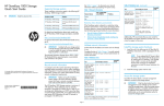
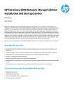
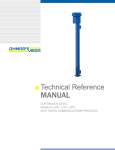
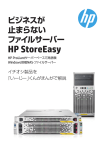
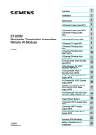
The HP StoreEasy 5000 Storage is the general name
for several 5xx0 hardware-software solutions. The
Microsoft Windows Storage Server 2012 Standard
Edition operating system is preinstalled and activated
on all systems. The instructions in this guide apply to
all HP StoreEasy 5000 Storage models unless
otherwise noted.
HP StoreEasy 5000 Storage
Quick Start Guide
Abstract
IMPORTANT:
Each storage system features HP server blades and
dense disk storage combined in a single 3U chassis
(Figure 1 (page 1)).
Read this document first.
Figure 1 HP StoreEasy 5000 Storage front view
1. Disk drive
2. Server blade 1, OS drives
3. Server blade 1, Bay 1
4. Server blade 2, Bay 2
5. Server blade 2, OS drives
6. Chassis fault LED
Figure 2 (page 1) shows components referenced
elsewhere in this guide.
Figure 2 HP StoreEasy 5000 Storage rear view
© Copyright 2012, 2013 Hewlett-Packard Development Company, L.P.
1. System fans (redundant)
HP Part Number: B7E02-96027
Published: June 2013
*B7E02-96027*
Edition: 2
2. HP 2-port 10 Gb I/O module
(2); these modules connect to
the integrated NIC located on
each server blade motherboard.
3. Intraconnect (internal switch 4. Drive fans (redundant)
connecting EMU)
5. SAS I/O module (2)
Page 1
6. Power button
7. Power supply (2)
Active Directory objects or certain administrative
permissions. See the following Microsoft articles for
more information:
8. HP 4–port, 1 Gb Ethernet
PCI-e module
9. HP 2-port, 1 Gb Ethernet I/O 10. Management port for iLO
module (connects to the
(servers 1 and 2), and Enclosure
mezzanine NIC in each server Manager Unit (EMU)
blade)
IMPORTANT: A System Recovery DVD is
included with your storage system. This DVD is
used to restore the storage system to factory
defaults and should be kept in a safe place.
•
How to Create a Cluster in a Restrictive Active
Directory environment
•
Failover Cluster Step-by-Step Guide: Configuring
Accounts in Active Directory
Validate network information
Confirm that the IP address and names are not already
in use.
Record network information
Complete the tests in Table 2 (page 2) to verify
network connectivity. Consult with your network
administrator to confirm test results.
It is critical to have the correct networking information
available before proceeding with the system
installation and configuration. It may be necessary to
pre-stage DNS information. Contact your system
administrator to clarify network configuration
requirements.
Table 2 Validation tests
Test
Ping the IP address ping <node 2 address>
of Node 2 from
Node 1.
IMPORTANT: Before joining the StoreEasy
system nodes to the Active Directory domain,
ensure that there is network connectivity between
each node and the domain controller.
Ping the name of
Node 2 from
Node 1.
The StoreEasy 5000 requires a minimum of 7 IP
addresses. These addresses may be statically assigned
or assigned by a DHCP server or both. If you are using
static addressing or a DHCP server that does not
automatically update DNS, ensure that both forward
and reverse DNS information (A and PTR records) is
pre-staged in the DNS server.
Ping the name of
Node 1 from
Node 2.
ping <node 2 fqdn>
ping <node1 name>
ping <node1 fqdn>
Verify forward and nslookup <node 1
reverse DNS
address>
information for
nslookup <node 1 name>
Node 1 is correct.
nslookup <node 1 fqdn>
Table 1 Network information
Fully qualified DNS
name (FQDN)
ping <node 2 name>
Ping the IP address ping <node 1>
of Node 1 from
Node 2.
Use Table 1 (page 2) to document your network
information before proceeding with system setup.
Network device
Command(s) to execute
Verify forward and nslookup <node 2
reverse DNS
address>
information for
nslookup <node 2 name>
Node 2 is correct.
nslookup <node 2 fqdn>
IP address
Enclosure Manager
Node 1 iLO
Ping the domain
controller from
Node 1.
Node 2 iLO
Node 1
Node 2
ping <domain controller
address>
ping <domain controller
name>
ping <domain controller
fqdn>
Cluster
First file server
Restrictive Active Directory environments
If the StoreEasy system is placed in a restrictive Active
Directory environment, it may require pre-staging
Page 2
Successful?
(Y/N)
Table 2 Validation tests (continued)
Test
Command(s) to execute
Ping the domain
controller from
Node 2.
ping <domain controller
address>
3.
Successful?
(Y/N)
4.
ping <domain controller
name>
Ensure that the disk drives are fully seated in the
disk drive drawer and disk enclosures.
To verify the lever is fully latched, pull on the lever
but do not press the release button. If any lever
appears to be loose, press the lever until it clicks.
Connect the storage system power cords to the
rack power supply using standard procedures.
ping <domain controller
fqdn>
Verify the network
path to the domain
controller and
DNS servers is
correct.
pingpath <domain
controller address>
Connect the storage system network cables
pingpath <domain
controller name>
The EMU provides connections to two types of
management processors:
pingpath <DNS server
address> (repeat for each DNS
server)
•
EMU processor
•
iLO processor for each server blade
pingpath <DNS server
name> (repeat for each DNS
server)
To simplify initial setup, the EMU and iLO processors
are configured for static addressing as follows:
•
EMU: 10.0.0.10
Additionally, verify that the DNS information is valid
for the cluster and file server. HP recommends that you
also verify the iLO and Enclosure Manager IP
address/name resolution; however, this is not critical
to support the cluster and file server.
•
Server 1 iLO: 10.0.0.11
•
Server 2 iLO: 10.0.0.12
•
Subnet: 255.255.255.0
Rack the storage system hardware
Figure 3 Storage system network ports
Figure 3 (page 3) identifies the network ports on the
rear of the storage system.
WARNING! The storage system is heavy.
Always use at least two people to move the
storage system into the rack.
1.
2.
If you ordered the storage system without the rack,
install the rail kit and storage system chassis by
following the HP 3U Storage System Rail Kit
Installation Instructions, packaged with the rail
kit.
Optionally, install any disk enclosures.
a. Add disk enclosures to the rack by following
the HP 2U Storage System Rail Kit Installation
Instructions, packaged with the rail kit.
b. Cable the disk enclosures to the storage
system chassis. For supported cabling, see
the HP StoreEasy 5000 Storage
Administrator Guide.
1. Server 1, 10 GbE port 1
2. Server 2, 10 GbE port 1
3. Server 1, 10 GbE port 2
4. Server 2, 10 GbE port 2
5. Intraconnect (internal switch 6. Enclosure Manager NIC
connecting EMU)
(includes iLO connections for
both servers)
IMPORTANT: Ensure that cabling in the
back of the rack does not interfere with
system operation or maintenance. Bind
cables loosely with cable ties and route
excess cable out of the way, along the side
of the rack.
7. Server 1, Mezz NIC, port 1
8. Server 2, Mezz NIC, port 1
9. Server 1, PCI-e NIC, ports
1-4
10. Server 2, PCI-e NIC, ports
1-4
Power on the storage system
1.
Page 3
Power on the disk enclosures, if any.
2.
Power on the storage system by pushing the
power button (6, Figure 3 (page 3)) on the back
of the chassis.
DHCP addressing options for IPV4. Available
options are:
NOTE: Approximately 30 seconds after
the storage system is powered on, the
server blades should start to power on
automatically. During this time, the
Enclosure Manager (EM) fault LED flashes
amber. After the EM has powered on, the
EM fault LED turns off and the EM health
LED turns solid green. Then, the server
blades start to power on.
5.
6.
Once the storage system power is on,
power on the server blades if they do not
automatically power on.
7.
NOTE: The amber chassis fault LED (6,
Figure 1 (page 1)) flashes if any component
fault is detected by the System Management
Homepage. A fault can be as minor as a cable
unplugged from a NIC port, and therefore may
not be cause for concern.
Configure iLO and EMU network ports
1.
2.
3.
4.
Connect a system (the configuration system) in
the environment or a laptop to the EMU port (10,
Figure 2 (page 1)).
Use an Ethernet cable connected directly to the
system or through a switch.
Configure the NIC on your system to a static
address of 10.0.0.20 with the subnet mask
255.255.255.0.
Configure iLO on blade 1. Open a web browser
and log in to iLO using the address http://
10.0.0.11. You are prompted to enter the user
name and password. The password for the iLO
Administrator is located on a pull-out tab on the
front of the server blade. After logging in, HP
recommends that you change the Administrator
password. To do so, select Administration→User
Administration in the iLO management interface.
Configure the network as required for your
environment. Select Administration→Network in
the iLO management interface. You can either
enable DHCP or edit the IP address details and
enter site-specific network settings.
•
Use DHCPV4 Supplied Gateway
•
Use DHCPv4 Supplied Static Routes
•
Use DHCPv4 Supplied Domain name
•
Use DHCPv4 DNS Servers
•
Use DHCPv4 Supplied WINS Servers
Click Apply to save your settings.
Configure iLO on blade 2. Open a web browser
and log in to iLO using http://10.0.0.12.
Repeat steps 4 and 5.
Connect to the Enclosure Manager software using
a secure shell application (PuTTY, for example).
Log in to the EMU with the EMU IP address
(10.0.0.10), port (22) and connection type (SSH).
When prompted, enter the EMU Administrator
password on the tear-away label attached to the
top left rear of the enclosure. Configure the
following:
a. Change your EMU Administrator password
by typing set password at the command
line prompt (optional).
b. To change the static IP address, type the
command set ipconfig static at the
command line prompt and follow the
instructions.
c. To change the EMU addressing to DHCP,
type set ipconfig dhcp at the command
line prompt. If you have a DHCP server in
your network, you can choose to assign the
IP address automatically by the DHCP server.
NOTE: You cannot connect to iLO or the EMU
from the configuration system until you change
the network settings on the configuration system.
HP recommends that you configure the EMU so that
administrators have remote network access to the unit.
See the HP StoreEasy 5000 Storage Administrator
Guide for network options.
Access the storage system
Configuration of the storage system, including the
cluster setup, is designed to be performed from a single
blade server. Connect to either one of the servers using
the remote console (iLO) or a local I/O diagnostic
(SUV) cable. The iLO remote console is the
recommended method. If you are using iLO, you must
have the EMU/iLO port (10, Figure 2 (page 1))
When you configure the iLO IP addressing to use
DHCP, ensure that you select the appropriate
Page 4
connected to your network, and iLO addresses
configured appropriately.
Completing initial configuration
NOTE: HP BladeSystem c-Class KVM Interface
Adapters are not supported.
After the servers reboot, continue the configuration
using the first node. A default Windows Administrator
password (HPinvent!) has been set and this is used
to log on automatically. Leave this Windows
Administrator password unchanged until you are
prompted for a new password in a later configuration
step. On logon, the HP ICT window is launched
automatically.
The server from which you choose to perform the
configuration will be designated the first node. The
other server will be designated the second node.
For instructions on using each access method, see the
HP StoreEasy 5000 Storage Administrator Guide or
the HP Integrated Lights-Out User Guide.
Use the HP ICT to perform setup tasks such as setting
the time zone, network configuration, changing the
computer name, joining a domain, and creating the
cluster. To create a cluster, each server will need
network connectivity to the domain controller and a
DNS server.
Set up Windows and discover second
node
When the storage system starts, the servers will begin
a first time setup procedure that takes approximately
10–15 minutes, including the Set Up Windows wizard.
Use only one server node (blade) to complete the setup
procedure.
IMPORTANT: HP strongly recommends that
you validate your configuration when using
clusters. Whether you create a cluster through
the ICT or the Failover Cluster Manager, one of
the first steps is validating your configuration
using the Microsoft cluster validation tool. If you
choose to skip the validation step, you can still
validate the cluster after it is created.
NOTE: Your storage system comes
pre-installed with the Microsoft Windows
Storage Server 2012 Standard Edition
operating system. No operating system
installation is required.
After the storage system installation process is
complete, you can use the browser (iLO) and remote
desktop methods to access and configure the storage
system. See the HP StoreEasy 5000 Storage
Administrator Guide for more information about using
these access methods.
In the Set Up Windows wizard, you are asked to
choose a language, country, and keyboard. After you
accept the EULA, the server you are connected to
attempts to discover the second server. This is done
over the internal switch (3, Figure 2 (page 1)). If the
second server is not ready, you may see a message
stating Cannot establish communication
with the second node. Click Retry to attempt
discovery, and repeat the retry until the second node
is discovered.
IMPORTANT: Be sure to install any available
software updates. You can be notified of
updates by subscribing to the HP Driver,
Support, and Security alerts e-mail list:
1. Go to http://www.hp.com/go/
StoreEasy5000.
2. Select Technical Support/Manuals.
3. On the product page that appears, select
Signup: driver and support alerts.
After the second node is discovered, there will be a
few more installation steps that occur automatically on
each server, and then both servers will reboot.
NOTE: If you click Cancel instead of Retry,
you must access the second node from iLO or
a local I/O diagnostic (SUV) cable and
manually follow the Set Up Windows wizard
on the second node. Because the discovery
process was not completed, there will also be
an extra step later to establish a connection
between the two nodes. You will find instructions
for this, if needed, in the online help of the Initial
Configuration Tasks (ICT).
To manually check for updates, perform steps
1 and 2. On the product page that appears,
select Download drivers and software. Select
your StoreEasy 5000 product and then select
the operating system. A list of available
downloads is displayed.
HP strongly recommends that you also install Insight
Remote Support as described in the HP StoreEasy
5000 Storage Administrator Guide.
Page 5
Supporting documentation
•
HP StoreEasy 5000 Storage Administrator Guide
•
HP StoreEasy 5000 Storage Release Notes
•
HP 3U Storage System Rail Kit Installation
Instructions (to install rails and rack the storage
system chassis)
•
HP 2U Storage System Rail Kit Installation
Instructions (to install rails and rack disk
enclosures)
You can find these documents from the following
website:
http://www.hp.com/support/manuals
Select NAS Systems in the storage group and then
select HP StoreEasy 5000 Storage. Localized versions
of this quick start guide are also located on the
Manuals page.
For iLO documentation, go to www.hp.com/go/iLO
and select HP iLO 3 Documentation.
Regulatory information
For important safety, environmental, and regulatory
information, see Safety and Compliance Information
for Server, Storage, Power, Networking, and Rack
Products, available at http://www.hp.com/support/
Safety-Compliance-EnterpriseProducts.
Documentation feedback
Send any errors, suggestions, or comments to
Documentation Feedback ([email protected]).
Page 6