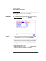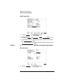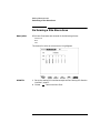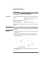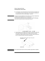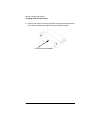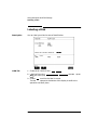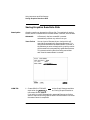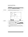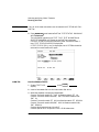
1
User’s Guide DSn/SONET Operation HP 37718A OmniBER 718 Copyright HewlettPackard Ltd.1998 All rights reserved. Reproduction, adaption, or translation without prior written permission is prohibited, except as allowed under the copyright laws. HP Part No. 37718-90022 Warranty WARNING The information contained in this document is subject to change without notice. Warning Symbols Used on the Product ! Hewlett-Packard makes no warranty of any kind with regard to this material, including, but not limited to, the implied warranties or merchantability and fitness for a particular purpose. The product is marked with this symbol when the user should refer to the instruction manual in order to protect the apparatus against damage. Hewlett-Packard shall not be liable for errors contained herein or for incidental or consequential damages in connection with the furnishing, performance, or use of this material. The product is marked with this symbol to indicate that hazardous voltages are present First edition, 09/98 Second Edition, 12/98 Printed in U.K. Hewlett-Packard Limited Telecommunications Networks Test Division South Queensferry West Lothian, Scotland EH30 9TG The product is marked with this symbol to indicate that a laser is fitted. The user should refer to the laser safety information in the Calibration Manual. User’s Guide DSn/SONET Operation HP 37718A OmniBER 718 About This Book This book tells you how to select the features that you want to use for your test. The selections available are presented in the following groups: • Transmit and receive interfaces • Test features, for example, the addition of errors and alarms to the test signal • Measurements including test timing • Storing, logging and printing results with general printer information • Using instrument and disk storage • Using the “Other” features. The selections available will depend on the options fitted to your instrument. The examples given in this book cover all options and therefore may include selections which are not available on your instrument. iv Contents 1 Setting the Interfaces Setting DSn Transmit Interface 2 Setting SONET Transmit Interface 4 Setting Jitter Transmit Interface 7 Setting Wander Transmit Interface 9 Setting SONET THRU Mode 11 Using Smart Test 13 Setting DSn Receive Interface 15 Setting SONET Receive Interface 17 Setting Jitter Receive Interface 18 Setting Extended Jitter Receive Interface 19 Setting Wander Receive Interface 20 2 Selecting Test Features Using Transmit Overhead Setup 22 Using Receive Overhead Monitor 24 Setting Overhead Trace Messages 26 Generating Overhead Sequences 27 Using Receive Overhead Capture 29 Adding Frequency Offset to SONET Signal 31 Adding Frequency Offset to the DSn Signal 33 Setting up Signaling Bits 34 Setting Transmit Structured Payload/Test Signal 37 Setting Receive Structured Payload/Test Signal 39 Setting Transmit N x 64 kb/s/N x 56 kb/s Structured Payload/Test Signal 40 Setting Receive N x 64 kb/s/N x 56 kb/s Structured Payload/Test Signal 42 v Contents Inserting an External DSn Payload/Test Signal 43 Dropping an External Payload/Test Signal 46 Adding Errors & Alarms at the SONET Interface 49 Adding Errors & Alarms to the DSn Interface/DSn Payload 50 Using FEAC Codes 51 Setting DSn Spare Bits 53 Adding Pointer Adjustments 54 Using Pointer Graph Test Function 61 Stressing Optical Clock Recovery Circuits 63 Generating Automatic Protection Switch Messages 64 Inserting & Dropping Data Communications Channel 65 3 Making Measurements Using Overhead BER Test Function 68 Test Timing 69 Making SONET Analysis Measurements 70 Making DSn Analysis Measurements 71 Measuring Frequency 72 Measuring Optical Power 73 Measuring Round Trip Delay 74 Monitoring Signaling Bits 76 Measuring Service Disruption Time 77 Performing a SONET Tributary Scan 80 Performing an SONET Alarm Scan 82 Performing a DSn Alarm Scan 83 Measuring Jitter 84 Measuring Extended Jitter 86 Measuring Wander 87 Measuring Jitter Tolerance 89 vi Contents Measuring Jitter Transfer 92 4 Storing, Logging and Printing Saving Graphics Results to Instrument Store 98 Recalling Stored Graph Results 99 Viewing the Bar Graph Display 101 Viewing the Graphics Error and Alarm Summaries 103 Logging Graph Displays 105 Logging Results 107 Logging on Demand 110 Logging Jitter Tolerance Results 112 Logging Jitter Transfer Results 114 Logging Results to Parallel (Centronics) Printer 116 Logging Results to HP-IB Printer 117 Logging Results to Internal Printer 118 Logging Results to RS-232-C Printer 119 Printing Results from Disk 120 Connecting an HP 850C DeskJet Printer to a Parallel Port 121 Changing Internal Printer Paper 122 Cleaning Internal Printer Print Head 125 5 Using Instrument and Disk Storage Storing Configurations in Instrument Store 128 Titling Configuration in Instrument Store 129 Recalling Configurations from Instrument Store 130 Formatting a Disk 131 vii Contents Labeling a Disk 132 Managing Files and Directories on Disk 133 Saving Graphics Results to Disk 140 Saving Data Logging to Disk 142 Saving Configurations to Disk 143 Recalling Configuration from Disk 144 Recalling Graphics Results from Disk 145 Copying Configuration from Instrument Store to Disk 146 Copying Configuration from Disk to Instrument Store 148 Copying Graphics Results from Instrument Store to Disk 150 6 Selecting and Using "Other" Features Coupling Transmit and Receive Settings 154 Setting Time & Date 155 Enabling Keyboard Lock 156 Enabling Beep on Received Error 157 Suspending Test on Signal Loss 158 Setting Error Threshold Indication 159 Setting Screen Brightness and Color 160 Dumping Display to Disk 161 Running Self Test 163 viii Contents 7 STS-1 SPE Background Patterns 8 ETSI/ANSI Terminology ETSI/ANSI Conversion and Equivalent Terms 170 ix Contents x 1 1 Setting the Interfaces This chapter tells you how to set the instrument interfaces to match the network being tested. Setting the Interfaces Setting DSn Transmit Interface Description DSn transmit interface settings should match network equipment settings of Rate, Termination and Line Code and determine the Payload to be tested. TIP: To set the Transmitter and Receiver to the same interface settings choose OTHER SETTINGS CONTROL COUPLED . HOW TO: 1 Choose the required SIGNAL rate. Rates of DS1, DS3, 2 Mb/s and 34 Mb/s are available. 2 If you have chosen 2 Mb/s as the SIGNAL rate, choose the required CLOCK SYNC source - internally generated or recovered from the received DSn signal. If Jitter, Option 204, 205 or 206, is fitted and SIGNAL 2 Mb/s is chosen a 2M REF choice is added to the menu. This allows you to choose the synchronization source for the 2 Mb/s reference. The synchronization source is supplied from the SONET Clock module. It can be internally generated, derived from an external clock or recovered from the SONET received signal. 2 Setting the Interfaces Setting DSn Transmit Interface 3 If DS1 or DS3 is chosen, choose the required OUTPUT LEVEL. 4 If you have chosen 2 Mb/s as the SIGNAL rate, choose the required TERMINATION. (At all other signal rates the impedance is fixed). 5 If you have chosen 2 Mb/s or DS1 as the SIGNAL rate, choose the required LINE CODE. (At 34 Mb/s and DS3 coding is fixed). 6 If required, choose the FREQUENCY OFFSET value. See “Adding Frequency Offset to the DSn Signal” page 33. 7 Choose the required PAYLOAD TYPE. If STRUCTURED is required FRAMED must be chosen. If STRUCTURED is chosen the DSn test signal must be set up. See “Setting Transmit Structured Payload/Test Signal” page 37. If you have chosen 2 Mb/s, DS1 or DS3 as the DSn signal rate, the Framed choice is expanded to provide a menu of framing types. 8 Choose the PATTERN type and the PRBS POLARITY. 3 Setting the Interfaces Setting SONET Transmit Interface Setting SONET Transmit Interface Description SONET transmit interface settings should match the network equipment settings of Rate, Wavelength and Mapping, determine the payload to be tested and set background conditions to prevent alarms while testing. TIP: If you wish to set the HP 37718A transmitter and receiver to the same interface settings choose OTHER SETTINGS CONTROL COUPLED . HOW TO: 1 Make your choice of SIGNAL rate. If Option 106, Dual Wavelength optical module, is fitted and an optical rate is chosen, choose the required wavelength (1550) or (1310). If STS-1 is chosen, choose the required interface level. Choose INTERNAL unless THRU MODE is required. If THRU MODE is chosen, see "Setting SONET THRU Mode " page 11. 2 Make your choice of CLOCK synchronization source. The RECEIVE clock synchronization choice depends on the SONET Receive Interface choice. EXTERNAL allows a choice of MTS, BITS or 10 MHz clocks. 3 If required choose the FREQUENCY OFFSET value. See “Adding Frequency Offset to SONET Signal” page 31. 4 Setting the Interfaces Setting SONET Transmit Interface 4 Choose FOREGROUND F/G MAPPING , BACKGROUND B/G MAPPING MAPPING and type of payload. Mapping may be selected from a pictorial display by moving the cursor to MAPPING and pressing SET . Use and to move between STS Layer choice, VT Layer choice and Payload Layer choice. Use and to choose the mapping. Use SET to confirm your choice and return to the SONET MAIN SETTINGS display. 5 If VT-6 mapping is chosen, VT CONCATENATION selection is enabled, choose OFF or the tributary at which the concatenation begins, VT6-2C through VT6-6C. The BACKGROUND, PATTERN IN OTHER VT-6’s is fixed at NUMBERED, that is, each VT-6 contains a unique number to allow identification in case of routing problems. 6 If required, choose DS1/2M/34M/DS3 OFFSET value. See “Adding Frequency Offset to SONET Signal” page 31 7 If FULL SPE, VT-6, VT-2 or VT-1.5 mapping is chosen, choose the test tributary CHANNEL, including the STS-3 for an OC-12/OC-48 signal. 8 Choose the payload framing under PAYLOAD TYPE or VT PAYLOAD. If STRUCTURED is required FRAMED must be chosen. If STRUCTURED is chosen, the Payload test signal must be set up. See “Setting Transmit Structured Payload/Test Signal” page 37. If INSERT is chosen, see “Inserting an External DSn Payload/Test Signal” page 43. 5 Setting the Interfaces Setting SONET Transmit Interface If you have chosen 2 Mb/s, DS1 or DS3 under Mapping, the Framed choice is expanded to provide a menu of framing types. 9 Choose the PATTERN type and PRBS polarity. 10 Choose the mapping required in the background (non-test) STS’s. 11 If VT mapping is chosen for the test STS, choose the PATTERN IN OTHER VT’s. 6 Setting the Interfaces Setting Jitter Transmit Interface Setting Jitter Transmit Interface Description: You can add jitter to the transmitted DSn or SONET signal at 2 Mb/s, 34 Mb/s, STS-3, OC-3, OC-12, and OC-48. You can source the jitter modulation internally or from an external source. HOW TO: 1 If you are adding jitter to the DSn signal, set up the DSn transmit interface. See Chapter “Setting DSn Transmit Interface”. 2 If you are adding jitter to the SONET signal, set up the SONET transmit interface. See “Setting SONET Transmit Interface” page 4. 3 Choose JITTER/WANDER JITTER . If you wish to add wander to the DSn or SONET signal, See “Setting Wander Transmit Interface” page 9. 4 Choose JITTER ON . If you wish to perform a Jitter Tolerance measurement, choose AUTO TOLERANCE . See “Measuring Jitter Tolerance” page 89. If you wish to perform a Jitter Transfer measurement choose TRANSFER FUNCTION . See “Measuring Jitter Transfer” page 92. 7 Setting the Interfaces Setting Jitter Transmit Interface 5 Choose the modulation source. If adding jitter to the DSn signal and EXTERNAL is chosen, connect the external source to the MOD IN port of the DSn Jitter TX module. Up to 10 UI of external jitter modulation can be added at the MOD IN port. If adding jitter to the SDH signal and EXTERNAL is chosen, connect the external source to the MOD IN port of the SONET Clock module. Up to 20 UI of external jitter modulation can be added at the MOD IN port. 6 Choose the JITTER MASK setting required. You can choose the jitter range, jitter modulating frequency and jitter amplitude if OFF is chosen. If you choose SWEPT , the HP 37718A will "sweep" through the ITU-T jitter mask (G.823 for DSn, G.958, G.825 or G.253 for SONET) adjusting the jitter amplitude according to the jitter frequency. If you choose SPOT , you can choose the "spot" jitter frequency. The jitter amplitude is adjusted and controlled according to your jitter frequency choice. TIP: If, when using the SWEPT MASK capability, a problem occurs around a certain frequency, this may require closer examination. Stop the sweep at that point by choosing SPOT . You can then control the "spot" jitter frequency to make closer examination of the problem. 8 Setting the Interfaces Setting Wander Transmit Interface Setting Wander Transmit Interface Description: You can add Wander to the 2 Mb/s DSn signal and the STS-3, OC-3, OC-12 or OC-48 SONET signal. HOW TO: DSn Wander (2 Mb/s) 1 Connect REF OUT on the SONET Clock module to REF IN on the DSn Jitter TX module (this provides the Wander Reference). 2 Set up the DSn transmit interface, choose CLOCK SYNC 2M REF and select the SOURCE required from the menu. See “Setting DSn Transmit Interface” page 2. 3 Choose JITTER/WANDER WANDER . If you wish to add jitter to the DSn signal, See “Setting Jitter Transmit Interface” page 7. 4 Choose WANDER ON . 5 Choose the modulation source. If EXTERNAL is chosen, connect the external source to the MOD IN port of the DSn Jitter TX module. Up to 10 UI of external wander modulation can be added. 9 Setting the Interfaces Setting Wander Transmit Interface 6 Choose the WANDER MASK setting required. You can choose the wander modulating frequency and wander amplitude if OFF is chosen. If you choose SPOT , you can choose the "spot" wander frequency. The wander amplitude is adjusted and controlled according to your wander frequency choice. SONET Wander (STS-3, OC-3, OC-12, OC-48) 7 Set up the SONET transmit interface. See “Setting SONET Transmit Interface” page 4. 8 Choose JITTER/WANDER WANDER . If you wish to add jitter to the SONET signal, see "Setting Jitter Transmit Interface " page 7. 9 Choose WANDER ON . 10 Choose the WANDER MASK setting required. You can choose the wander modulating frequency and wander amplitude if OFF is chosen. If you choose SPOT , you can choose the "spot" wander frequency. The wander amplitude is adjusted and controlled according to your wander frequency choice. 10 Setting the Interfaces Setting SONET THRU Mode Setting SONET THRU Mode Description THRU mode is used to non-intrusively monitor SONET lines where no protected monitor points are available. As THRU mode locks some user settings, you must set SIGNAL RATE, STS rate, STS-1 SPE CHANNEL (if appropriate) before selecting THRU mode. The entire frame can be errorred at a user defined rate if PAYLOAD OVERWRITE and TOH+POH CHANNEL OVERWRITE are both set to OFF . If either overwrite is enabled the ENTIRE FRAME ERROR RATE function is disabled. OC-1/STS-1, OC-3/STS-3 You can substitute a new payload, Section and Line Overhead (TOH) and Path overhead (POH) in the received OC-1/STS-1 or OC-3/STS-3 signal for testing. OC-12, OC-48 The overhead and payload may be overwritten for STS-3c SPE and AU3. PAYLOAD OVERWRITE is not available for STS-12C or STS-48C. TOH+POH CHANNEL overwrite is available for STS-12C and STS-48C. HOW TO: 1 Make the required SIGNAL RATE, MAPPING and CHANNEL choices on the SONET TRANSMIT and RECEIVE displays, See "Setting SONET Transmit Interface " page 4 and "Setting SONET Receive Interface " page 17. 11 Setting the Interfaces Setting SONET THRU Mode 2 Make the PAYLOAD OVERWRITE choice required. If STS-3c SPE, STS-1 SPE, VT-6, VT-2 or VT-1.5 is chosen, the Section, Line and Path CVs are recalculated before transmission and the Mapping, Selected VT, VT Payload, Pattern, Tributary Offset and Pattern in other VT’s settings are displayed. To choose the settings in these, See "Setting SONET Transmit Interface " page 4, steps 4 through 10. 3 Make the TOH+POH CHANNEL OVERWRITE choice required. You can only modify those overhead bytes available under TRANSMIT SONET TEST FUNCTION SONET : Errors & Alarms, Sequences, Overhead BER, APS Messages and DCC Insert. The Section, Line and Path CVs are recalculated before transmission. 4 If you wish to add jitter to the STS-3, OC-3, OC-12 or OC-48 signal, See “Setting Jitter Transmit Interface” page 7. 12 Setting the Interfaces Using Smart Test Using Smart Test Description The Smart Test function can help speed-up configuring the instrument in two ways. 1 A Smartsetup feature that will attempt to configure the instrument to receive the incoming signal. 2 A series of “links” that provide quick access to some of the most frequently used features of the instrument. Note that these tests are run with the instrument in its current configuration, no attempt is made to set the instrument to the requirements of the test. Smartsetup can help the user by attempting to identify the incoming signal structure and detect mixed payload signal structures. HOW TO USE SMARTSETUP: 1 Connect the HP 37718A to the network and choose if necessary the required SONET RECEIVE interface on the HP 37718A (Smartsetup will select DSn or SONET/SDH, but can not select between SONET and SDH). 2 Press SMART TEST . The display will show the Smart Test menu above. 3 Press either SET or SELECT . 13 Setting the Interfaces Using Smart Test 4 In SONET mode the incoming signal will be identified on the top line of the display, and under this the payload mappings, the J1 Trace and C2 byte indicators are displayed on the bottom lines. 5 Use the and keys to display the J1 Trace information for each STS SPE. When the STS SPE of interest has been identified choose either VIEW PAYLOAD or PRBS SEARCH . 6 Choosing VIEW PAYLOAD will identify and display the payload mapping of the TUG structured signal, as shown below. Choose the required tributary using and . 7 There are four choices available at this point: SETUP RX which sets the receiver to receive the selected tributary. TROUBLE SCAN which sets the receiver to receive the selected tributary, exits to the RESULTS TROUBLE SCAN display and starts gating. VIEW LABELS which displays the C2/V5/J1/J2 trace information for the selected tributary. TOP LEVEL which returns the display to the STS SPE selection window. 8 Choosing PRBS SEARCH at Step 5 will prompt you for additional information about patterns and which mapping to search. When the required data has been entered press GO . 9 When the search is complete a tributary display appears, with any tributaries containing the required PRBS indicated with a “P”. Choose the required tributary using and . 14 Setting the Interfaces Setting DSn Receive Interface Setting DSn Receive Interface Description DSn Receive interface settings should match the network equipment settings of Rate, Termination and Line Code and determine the Payload to be tested. TIP: To set the transmitter and receiver to the same interface settings choose OTHER SETTINGS CONTROL COUPLED . HOW TO: 1 Choose the required SIGNAL rate. 2 If you have chosen 2 Mb/s as the SIGNAL rate, choose the required TERMINATION. (At all other rates the impedance is fixed.) 3 If you have chosen 2 Mb/s or DS1 as the SIGNAL rate, choose the required LINE CODE. (At 34Mb/s and DS3 coding is fixed.) 4 If you are measuring at the network equipment monitor point, set the LEVEL field to MONITOR . In this case the received signal will be 20 to 30 dB below the normal level. Choose the GAIN required to return the received signal to normal. Choose EQUALIZATION ON to compensate for cable losses if required. 15 Setting the Interfaces Setting DSn Receive Interface 5 Choose the PAYLOAD TYPE. If STRUCTURED is required FRAMED must be chosen. If STRUCTURED is chosen, the DSn test signal must be set up. See “Setting Transmit Structured Payload/Test Signal” page 37. If you chose 2 Mb/s, DS1 or DS3 as the PDH/DSn SIGNAL rate, the FRAMED choice is expanded to provide a menu of framing types. 6 Choose the PATTERN type and the PRBS POLARITY required. 16 Setting the Interfaces Setting SONET Receive Interface Setting SONET Receive Interface Description SONET Receive interface settings should match the network equipment settings of Rate and Mapping, and determine the payload to be tested. TIP: If you wish to set the HP 37718A transmitter and receiver to the same interface settings, choose OTHER SETTINGS CONTROL COUPLED . HOW TO: 1 Choose the required SIGNAL source. If STS-1 or STS-3 is chosen, choose the required LEVEL. If the LEVEL chosen is MONITOR choose the required GAIN. 2 Choose mapping and type of payload. 3 If VT-6 mapping is chosen, and CONCATENATION is enabled, choose the tributary at which the concatenation begins. If VT-6, VT-2 or VT-1.5 mapping is chosen, choose the test tributary under CHANNEL. 4 Choose the payload framing under PAYLOAD TYPE or VT PAYLOAD. If STRUCTURED is required FRAMED must be chosen. If STRUCTURED is chosen the Payload test signal must be set up. See “Setting Receive Structured Payload/Test Signal” page 39. If DROP is chosen, see “Dropping an External Payload/Test Signal” page 46. 5 Choose the PATTERN type and PRBS polarity. 17 Setting the Interfaces Setting Jitter Receive Interface Setting Jitter Receive Interface Description: Jitter and error measurements are made simultaneously when a jitter option is fitted. The measurements are made on the normal input to the DSn or SONET receiver and the interface selections are the normal Receiver selections. The jitter receive interface is selected with RECEIVE PDH/DSn JITTER or RECEIVE SONET JITTER MEASUREMENT TYPE JITTER . The choices made on the jitter receive interface determine the jitter measurement range, the threshold level for determining a jitter hit and which filters are used in the jitter measurement. HOW TO: 1 Choose MEASUREMENT TYPE JITTER . 2 Choose the RECEIVER RANGE - the jitter measurement range. 3 Choose the HIT THRESHOLD level - if the received jitter exceeds the value chosen a jitter hit is recorded. 4 Choose the FILTER you wish to include in the peak to peak and RMS jitter measurement. 18 Setting the Interfaces Setting Extended Jitter Receive Interface Setting Extended Jitter Receive Interface Description: Extended Jitter measurements are made in a jitter bandwidth of 0.1 Hz to 25 kHz. These measurements are made at the upper end of the standard wander frequency range and the lower end of the standard jitter frequency range. The extended jitter receive interface is selected with RECEIVE PDH/DSn JITTER or RECEIVE SONET JITTER MEASUREMENT TYPE EXTENDED . The choices made on the jitter receive interface determine the threshold level for determining a jitter hit. The measurement Range and the Filters are not selectable. HOW TO: 1 Choose MEASUREMENT TYPE EXTENDED . 2 Choose the HIT THRESHOLD level - if the received jitter exceeds the value chosen a jitter hit is recorded. 19 Setting the Interfaces Setting Wander Receive Interface Setting Wander Receive Interface Description: You can measure Wander at all DSn and SONET rates. An external timing reference should be selected on the TRANSMIT PDH/DSn or SONET MAIN SETTINGS display to ensure accurate Wander results. HOW TO: 1 Choose an external timing reference on the TRANSMIT SONET MAIN SETTINGS display. See, “Setting SONET Transmit Interface” page 4. 2 If you intend to measure wander on a DSn signal, set up the DSn receive interface. See, “Setting DSn Receive Interface” page 15. 3 If you intend to measure wander on a SONET signal, set up the SONET receive interface. See, “Setting SONET Receive Interface” page 17. 4 Choose MEASUREMENT TYPE WANDER . 5 Choose the wander HIT THRESHOLD - if the received wander exceeds the value chosen a wander hit is recorded. 20 2 2 Selecting Test Features Selecting Test Features Using Transmit Overhead Setup Description You can set an overhead byte to a known static state to aid troubleshooting, for example to quickly check for "stuck bits" in path overhead bytes. Transport Overhead, Path Overhead, Trace Messages and Labels can be set using this feature. HOW TO: 1 Set up the SONET transmit interface and payload required. See "Setting SONET Transmit Interface " page 4. 2 Choose the type of overhead to SETUP. If OC-12 or OC-48 is chosen as the SONET interface, choose the STS3# and STS-1# you wish to set up. If STS-3 is chosen as the SONET interface, choose the STS-1# you wish to set up. DEFAULT - Use to set all overhead bytes to the standard values defined by ITU-T. If a test function is active then the overhead byte value is determined by the choices made in the Test Function. If APS Messages is chosen, for example, K1K2 value is set by the APS Messages setup. 22 Selecting Test Features Using Transmit Overhead Setup If TOH (Transport Overhead) is chosen, choose the STS-1 to be displayed. Many bytes in STS-1# 2 and STS-1#3 are unlabeled as the other overhead functions have not yet been defined. If STS-1# 1,2,3 is chosen, the hexadecimal value of all 81 bytes of the STS-3 section & line overhead selected are displayed (all 324 bytes of an OC-12 or 1,296 bytes of an OC-48 are displayed 81 bytes at a time by selecting each STS-3 in turn). The value of the bytes can be set using DECREASE DIGIT INCREASE DIGIT . If BYTE NAMES is chosen, the labels for the STS-1# 1,2,3 overhead bytes are displayed. 3 If POH (Path Overhead) is chosen, choose the TYPE of overhead within STS-1 under test to be setup. J1 and J2 bytes can be set under Path Overhead or Trace Messages. H4 byte has a choice of sequences for VT-2, VT-1.5 and VT-6 mapping: Full Sequence - 48 byte binary sequence. Reduced Sequence - Binary count sequence of 0 to 3 i.e. 111111(00 to 11). COC1 Sequence - Binary count sequence of 0 to 3 i.e. 110000(00 to 11). H4 byte is transmitted as all zero’s for 34 Mb/s and DS3. 4 If TRACE MESSAGES is chosen, see "Setting Overhead Trace Messages " page 26. NOTE Any bit of an overhead byte which is displayed as x or s cannot be set at any time. All other bits can be set to 0 or 1. TIP: You can set all overhead bytes to the default state by selecting SETUP DEFAULT . You can set all overhead bytes and test functions to the default state by recalling Stored Settings [0] on the OTHER display. 23 Selecting Test Features Using Receive Overhead Monitor Using Receive Overhead Monitor Description When first connecting to a SONET network, a start up confidence check can be made by viewing the behavior of all the overhead bytes. If the SONET network shows alarm indications, some diagnosis of the problem may be gained from viewing all the overhead bytes.The OVERHEAD MONITOR display is updated once per second (once per 8000 frames) approximately. TIP: A snapshot of the received overhead can be logged to the chosen logging device. See "Logging on Demand " page 110. HOW TO: 1 Set up the receive SONET interface and payload as required. See “Setting SONET Receive Interface” page 17. 2 Choose the type of overhead to MONITOR. 3 If TOH (Transport Overhead) is chosen, choose the STS-3 # and STS-1# to be displayed. Many bytes in STS-1# 2 and STS-1#3 are unlabeled because the other overhead functions have not yet been defined. If STS-1# 1,2,3 is chosen, the hexadecimal value of all 81 bytes of section overhead is displayed (all 324 bytes of an OC-12 or 1,296 bytes of an OC-48 are displayed 81 bytes at a time by selecting each STS-3 in turn).The value of the bytes can be set using DECREASE DIGIT INCREASE DIGIT 24 . Selecting Test Features Using Receive Overhead Monitor If BYTE NAMES is chosen, the labels for the STS-1# 1,2,3 overhead bytes are displayed. 4 If POH (Path Overhead) is chosen, choose the source of the overhead, SPE or VTSPE. J1 and J2 bytes can be monitored under Path Overhead or Trace Messages 5 If TRACE MESSAGES is chosen, you can monitor a data message to verify portions of the network. If the 16 byte CRC7 message structure is detected, the 15 characters within the message are displayed. If the CRC7 structure is not detected in J1, the 64 byte message format is assumed and displayed. If the CRC7 structure is not detected for J0 or J2, all 16 bytes are displayed. 6 If LABELS is chosen, the S1 sync status, STS path label (C2) and the VT Path label (V5) are monitored. 7 If APS MESSAGES is chosen, choose the TOPOLOGY, LINEAR (GR253) or RING (GR-1230). The K1 and K2 bits are monitored. TIP: If any abnormal behavior is observed on a particular path or section overhead byte, or an associated group of bytes (3XA1,3XA2; D1 - D3), the RECEIVE TEST FUNCTION display of OVERHEAD CAPTURE can be used to "Zoom" in on the suspect byte or bytes on a frame by frame basis. See "Using Receive Overhead Capture " page 29. 25 Selecting Test Features Setting Overhead Trace Messages Setting Overhead Trace Messages Description You can insert a data message to verify portions of the network: J0 verifies the section overhead. J1 verifies the STS-1 SPE or STS-3c SPE path connection. J2 verifies the VT SPE path connection. HOW TO: 1 Choose the message for insertion in the chosen trace channel. Choosing LABELS in TRACE MESSAGES allows the setting of the S1 SYNC STATUS, STS PATH LABEL (C2) and VT PATH LABEL (V5). 26 Selecting Test Features Generating Overhead Sequences Generating Overhead Sequences Description You may insert a pattern into a functional group of overhead bytes for testing or troubleshooting purposes. HOW TO: 1 Set up the SONET transmit interface and payload required. See “Setting SONET Transmit Interface” page 4. 2 Choose the type of sequence required. SINGLE RUN - runs the sequence once and then stops. REPEAT RUN - runs the sequence repeatedly until STOPPED is chosen. 3 Choose the overhead type as required. SOH- Section Overhead LOH- Line Overhead POH - Path Overhead 4 Choose the byte or bytes of overhead required. 5 Set up the required number of data patterns and the number of frames in which each data pattern should appear. Your sequence is derived from up to 5 blocks of hexadecimal data. Each block can be transmitted in up to 64,000 frames. The data and the number of frames are set using DECREASE DIGIT INCREASE DIGIT . 27 Selecting Test Features Generating Overhead Sequences 6 Start the sequence by choosing START . NOTE When you start the sequence illustrated, one Out of Frame alarm and one Loss of Frame alarm should occur every eight seconds. 28 Selecting Test Features Using Receive Overhead Capture Using Receive Overhead Capture Description Section, Line and Path overhead provide network support functions, responding dynamically to network conditions and needs. It is therefore useful to capture overhead activity on a frame by frame basis. TIP: The Overhead Capture display can be logged to the chosen logging device. See "Logging on Demand " page 110. HOW TO: 1 Set up the receive SONET interface and payload as required. See “Setting SONET Receive Interface” page 17. 2 Choose the overhead type as required. SOH- Section Overhead LOH- Line Overhead POH- Path Overhead 3 Choose the Byte or bytes of overhead to be captured. Choose the TRIGGER to determine the start point of the capture. OFF - starts immediately the capture is initiated. Can be used to provide a frame by frame monitor of the chosen byte or bytes. ON -captures activity after your specified overhead state has occurred. Can be used for transient detection from a specified expected state. 29 Selecting Test Features Using Receive Overhead Capture ON NOT - captures activity after the first occurrence of a deviation from your specified overhead state. Can be used for transient detection from a specified expected state. 4 Up to 16 records of overhead state are provided. Each record will represent between 1 and 64,000 frames. A capture is started by pressing CAPTURE START and terminates when up to 16 records have been captured. The capture can be terminated earlier by pressing CAPTURE STOP . 30 Selecting Test Features Adding Frequency Offset to SONET Signal Adding Frequency Offset to SONET Signal Description Frequency offset can be added to the SONET interface rate signal and to the payload signal. HOW TO: SONET Line Rate Offset 1 Choose the amount of frequency offset required. You can set the Frequency Offset in the range -999 ppm to +999 ppm in 1 ppm steps using DECREASE DIGIT INCREASE DIGIT and . The amount of applied Frequency Offset can be varied while measurements are taking place. If the value of the SONET line rate offset chosen is sufficient to cause the maximum stuff rate to be exceeded, the asynchronous payload is offset to prevent bit errors occurring and the maximum stuff rate is maintained. When Floating Byte 2 Mb/s is chosen, in conjunction with SONET line rate offset, the chosen tributary will be offset as the line rate is offset. (No pointer movements). 31 Selecting Test Features Adding Frequency Offset to SONET Signal Tributary Offset ±100 ppm 1 Choose the amount of tributary offset required. You can set the Offset in the range -100 ppm to +100 ppm in 1 ppm steps using DECREASE DIGIT INCREASE DIGIT and . The amount of applied Frequency Offset can be varied while measurements are taking place. Tributary offset affects the stuff rate but does not cause pointer movements and can be used to test mapping jitter. If the combined value of SONET line rate offset and tributary offset chosen is sufficient to cause the maximum stuff rate to be exceeded the payload is offset to prevent bit errors occurring and the maximum stuff rate is maintained. 32 Selecting Test Features Adding Frequency Offset to the DSn Signal Adding Frequency Offset to the DSn Signal Description You can add frequency offset to the interface DSn SIGNAL at all rates. Frequency Offset can be added at preset ITU values or as User defined values in the range ±100 ppm. The preset values change with the SIGNAL rate chosen as shown: DS-1 (1.544 Mb/s) 2 Mb/s (E1) 34 Mb/s (E3) DS-3 (44.736 Mb/s) HOW TO: + 32 ppm + 50 ppm + 20 ppm + 20 ppm −32 ppm −50 ppm −20 ppm −20 ppm 1 Choose the FREQUENCY OFFSET required. 2 If you choose USER OFFSET, you can set the frequency offset to be between -100 ppm and +100 ppm in 1 ppm steps. Select the field immediately below USER OFFSET and use and to set the DECREASE DIGIT , INCREASE DIGIT , frequency offset. (The amount of frequency offset can be varied while measurements are taking place.) 33 Selecting Test Features Setting up Signaling Bits Setting up Signaling Bits Description When transmitting 2.048 Mb/s signals with timeslot-16 CAS (PCM30 or PCM30CRC) multiframing the state of A,B,C,D signaling bits can be set. The signaling bits of all timeslots are set to the user-defined 4 bit value. When transmitting a DS1 framed, structured signal the values of the A,B signaling bits for D4 and SLC-96 payloads, and A,B,C,D signaling bits for ESF payloads can be defined. HOW TO Transmit a 2 Mb/s signal with user-defined signaling bits DSn Operation 1 Choose PDH/DSn on the TRANSMIT display. 2 Choose SIGNAL 2 Mb/s and PAYLOAD TYPE PCM30 or PCM30CRC on the MAIN SETTINGS display. 3 If UNSTRUCTURED is chosen set the 2M CAS ABCD bits value on the MAIN SETTINGS display. If STRUCTURED is chosen set the 2M CAS ABCD bits value on the STRUCTURED SETTINGS display. 34 Selecting Test Features Setting up Signaling Bits SONET Operation 1 Choose SONET on the TRANSMIT display 2 Choose MAPPING ASYNC 2Mb/s or FL BYTE 2Mb/s and VT PAYLOAD PCM30 or PCM30CRC on the MAIN SETTINGS display. 3 If UNSTRUCTURED is chosen set the 2M CAS ABCD bits value on the MAIN SETTINGS display. If STRUCTURED is chosen set the 2M CAS ABCD bits value on the STRUCTURED SETTINGS display. HOW TO Transmit a DS1 payload signal with user-defined signaling bits DSn Operation 1 Choose PDH/DSn on the TRANSMIT display. 35 Selecting Test Features Setting up Signaling Bits 2 Choose SIGNAL DS1 or DS3 , and PAYLOAD TYPE STRUCTURED on the MAIN SETTINGS display 3 Choose TEST SIGNAL 56 kb/s or Nx56 kb/s on the STRUCTURED SETTINGS display. 4 Set the A,B bits (for D4 and SLC-96) and A,B,C,D bits (for ESF) as required. SONET Operation 1 Choose SONET on the TRANSMIT display. 2 Choose MAPPING ASYNC DS1 or DS3 and VT PAYLOAD STRUCTURED on the MAIN SETTINGS display 3 Choose TEST SIGNAL 56 kb/s or Nx56 kb/s on the STRUCTURED SETTINGS display . 4 Set the A,B bits (for D4 and SLC-96) and A,B,C,D bits (for ESF) as required. 36 Selecting Test Features Setting Transmit Structured Payload/Test Signal Setting Transmit Structured Payload/Test Signal Description Structured DSn Payload/Test Signal settings determine the SONET payload or the DSn test signal to be tested and set any background (non test) conditions to prevent alarms while testing. TIP: If you wish to set the HP 37718A transmitter and receiver to the same Payload settings, choose OTHER SETTINGS CONTROL COUPLED . HOW TO: 1 Choose the required TEST SIGNAL rate. If Nx64 kb/s or N X 56 kb/s is chosen, see "Setting Transmit N x 64 kb/s/N x 56 kb/s Structured Payload/Test Signal " page 40. 2 Choose the PAYLOAD framing pattern. If TEST SIGNAL 2Mb/s is chosen INSERT 2 Mb/s is added to the PAYLOAD menu. See "Inserting an External DSn Payload/Test Signal " page 43. If TEST SIGNAL DS1 is chosen INSERT DS1 is added to the menu. See "Inserting an External DSn Payload/Test Signal " page 43. 3 Choose the test tributary in the structured payload, under 34Mb, 8Mb, 2Mb, 64 kb/s or DS2, DS1, 56 kb/s. 4 Choose the PATTERN type and PRBS POLARITY. 37 Selecting Test Features Setting Transmit Structured Payload/Test Signal 5 Choose the B/G PATTERN. The B/G PATTERN in the non test 56/64 kb/s timeslots is fixed as NUMBERED, that is, each timeslot contains a unique number to allow identification in case of routing problems. Signaling 6 If a 2 Mb/s PAYLOAD with PCM30 or PCM30CRC framing, or 56 kb/s or Nx56kb/s Test Signal is chosen. See, "Setting up Signaling Bits " page 34. 38 Selecting Test Features Setting Receive Structured Payload/Test Signal Setting Receive Structured Payload/Test Signal Description Structured DSn Payload/Test Signal settings determine the SONET payload or the DSn test signal to be tested. TIP: If you wish to set the HP 37718A transmitter and receiver to the same Payload settings, choose OTHER STORED SETTINGS COUPLED . HOW TO: 1 Choose the required Test Signal rate. If N x 64 kb/s or N x 56 kb/s is chosen, see "Setting Receive N x 64 kb/s/N x 56 kb/s Structured Payload/Test Signal " page 42. 2 Choose the Framing pattern of the PAYLOAD. If TEST SIGNAL 2 Mb/s is chosen, DROP 2 Mb/s is added to the menu. See "Dropping an External Payload/Test Signal " page 46. If TEST SIGNAL DS1 is chosen, DROP DS1 is added to the menu. See "Dropping an External Payload/Test Signal " page 46. 3 Choose the test tributary within the structured payload, under 34Mb, 8Mb, 2Mb, 64 kb or DS2, DS1, 56 kb/s. 4 Choose the PATTERN type and PRBS polarity. 39 Selecting Test Features Setting Transmit N x 64 kb/s/N x 56 kb/s Structured Payload/Test Signal Setting Transmit N x 64 kb/s/N x 56 kb/s Structured Payload/Test Signal Description Wideband services such as high speed data links and LAN interconnection require a bandwidth greater than 56/64 kb/s but less than DS1/2 Mb/s for example 112 kb/s or 336 kb/s. These wideband signals are sent in a DS1/2 Mb/s frame by sharing the signal between multiple timeslots. N x 64kb/s/N x 56 kb/s structured payload allows a test pattern to be inserted across a number of timeslots even if the chosen timeslots are non-contiguous. HOW TO: 1 Choose the required Test Signal rate. 2 Choose the Framing pattern of the 2M or DS1 PAYLOAD. 3 Choose the test timeslots within the structured payload using and softkeys. As each DESELECT ALL DESELECT SELECT timeslot is selected, an * marks the chosen timeslot. In the example above Timeslots 3, 5, 9, 21, 22, 23 are selected for test. 4 Choose the PATTERN type and PRBS polarity. 5 Choose the B/G PATTERN. 40 Selecting Test Features Setting Transmit N x 64 kb/s/N x 56 kb/s Structured Payload/Test Signal 6 The B/G PATTERN in the non-test 56/64 kb/s timeslots is fixed as NUMBERED, that is, each timeslot contains a unique identification number. Signaling 7 If a 2 Mb/s PAYLOAD with PCM30 or PCM30CRC framing, or 56 kb/s or Nx56kb/s Test Signal is chosen. See, "Setting up Signaling Bits " page 34. 41 Selecting Test Features Setting Receive N x 64 kb/s/N x 56 kb/s Structured Payload/Test Signal Setting Receive N x 64 kb/s/N x 56 kb/s Structured Payload/Test Signal Description Wideband services such as high speed data links and LAN interconnection require a bandwidth greater than 56/64 kb/s but less than DS1/2 Mb/s e.g. 112 kb/s or 336 kb/s. These wideband signals are sent in a DS1/2 Mb/s frame by sharing the signal between multiple timeslots. N x 64kb/s and N x 56 kb/s structured payload/test signal allows the test Timeslots to be chosen for error measurement even when the Timeslots are non contiguous. HOW TO: 1 Choose the required Test Signal rate. 2 Choose the Framing pattern of the 2M or DS1 PAYLOAD. 3 Choose the test timeslots within the structured payload using and softkeys. As each DESELECT ALL DESELECT SELECT timeslot is chosen an * marks the chosen timeslot. In the example above Timeslots 3, 5, 9, 21, 22, 23 are chosen for test. 4 Choose the PATTERN type and PRBS polarity. 42 Selecting Test Features Inserting an External DSn Payload/Test Signal Inserting an External DSn Payload/Test Signal Description You can insert a DSn signal from external equipment into the SONET signal, or you can insert 2 Mb/s or DS1 into the structured DSn signal, as shown in the table below. DS3 and 34 Mb/s can only be inserted if SONET is chosen as the receive interface. 2 Mb/s or DS1 can be inserted from a structured or non-structured SONET payload and from a structured DSn signal. RATE HOW TO: Availability Option DS3 SONET 011 Only 34Mb/s SONET 010 and 011 2Mb/s DSn & SONET 010 and 011 DS1 DSn & SONET 011 Only Insert 34 Mb/s & DS3 1 Connect the external payload to the 75Ω IN port of the PDH/DSn receive module. 2 Set up the required transmit SONET interface, and choose VT PAYLOAD INSERT 34 Mb/s or INSERT DS3 as required. 43 Selecting Test Features Inserting an External DSn Payload/Test Signal Insert 2 Mb/s or DS1 (Unstructured SONET Payload) 1 Connect the external payload to the MUX port of the PDH/DSn Transmit module. If 2 Mb/s connect to 75Ω MUX port. If DS1 connect to 100Ω MUX port. 2 Set up the required transmit SONET interface, and choose VT-2 or VT-1.5 MAPPING and VT PAYLOAD INSERT 2 Mb/s or INSERT DS1 . Insert 2 Mb/s or DS1 (Structured SONET Payload or Structured DSn) 1 Connect the external payload to the MUX port of the DSn Transmit module. If 2 Mb/s connect to 75Ω MUX port. If DS1 connect to 100Ω MUX port. 44 Selecting Test Features Inserting an External DSn Payload/Test Signal Structured SONET Payload 2 Set up the required transmit SONET interface. See "Setting SONET Transmit Interface " page 4. 3 Set up the SONET structured payload. See "Setting Transmit Structured Payload/Test Signal " page 37. 4 Choose 2M PAYLOAD/DS1 PAYLOAD INSERT 2 Mb/s or INSERT DS1 . 5 Choose the LINE CODE. Structured DSn 6 Set up, the required transmit DSn interface, See "Setting DSn Transmit Interface " page 2. 7 Set up the DSn Test Signal interface. See "Setting Transmit Structured Payload/Test Signal " page 37 8 Choose 2M PAYLOAD/DS1 PAYLOAD INSERT 2 Mb/s or INSERT DS1 . 9 Choose the LINE CODE. 45 Selecting Test Features Dropping an External Payload/Test Signal Dropping an External Payload/Test Signal Description You can drop a DSn signal from the received payload or drop 2 Mb/s or DS1 from the structured DSn signal to external equipment as shown in the table below. DS3 and 34 Mb/s can only be dropped if SONET is chosen as the receive interface. 2 Mb/s or DS1 can be dropped from a structured or non-structured SONET payload and from a structured DSn signal. RATE HOW TO: Availability Option DS3 SONET 011 Only 34Mb/s SONET 010 and 011 2Mb/s DSn & SONET 010 and 011 DS1 DSn & SONET 011 Only Drop 34 Mb/s & DS3 1 Connect the 75Ω OUT port of the DSn Transmit module to the external equipment. 2 Set up the receive SONET interface, and choose VT PAYLOAD , DROP 34 Mb/s or DROP DS3 . If DROP DS3 is chosen, choose the DS3 output level. 46 Selecting Test Features Dropping an External Payload/Test Signal Drop 2 Mb/s /DS1 (Unstructured SONET Payload) 1 Connect the DEMUX port of the DSn module to the external equipment. 2 Set up the required receive SONET interface, and choose VT-2 or VT-1.5 MAPPING and VT PAYLOAD DROP 2 Mb/s or DROP DS1 . 3 Choose the required LINE CODE. Drop 2 Mb/s/DS1 (Structured SONET Payload or Structured DSn 1 Connect the DEMUX port of the Receive DSn module to the external equipment. If 2 Mb/s connect to 75Ω DEMUX port. If DS1 connect to 100Ω DEMUX port. 47 Selecting Test Features Dropping an External Payload/Test Signal Structured SONET Payload 2 Set up the required receive SONET interface. See "Setting SONET Receive Interface " page 17. 3 Set up the SONET structured payload. See "Setting Receive Structured Payload/Test Signal " page 39. 4 Choose 2M PAYLOAD DROP 2 Mb/s or DS1 PAYLOAD DROP DS1 . 5 Choose the LINE CODE. Structured DSn 6 Set up, the required receive DSn interface, See "Setting DSn Receive Interface " page 15. 7 Set up the DSn Test Signal interface. See "Setting Receive Structured Payload/Test Signal " page 39 8 Choose 2M PAYLOAD DROP 2 Mb/s or DS1 PAYLOAD DROP DS1 . 9 Choose the LINE CODE. 48 Selecting Test Features Adding Errors & Alarms at the SONET Interface Adding Errors & Alarms at the SONET Interface Description Errors and alarms can be added to the SONET interface signal during testing. HOW TO: 1 Set up the SONET transmit interface and payload required. See "Setting SONET Transmit Interface " page 4. 2 Choose the ERROR ADD TYPE and RATE required. Errors can be added at preset rates and at USER programmable rate. With the exception of ENTIRE FRAME and A1A2 FRAME, errors can be added at ERROR ALL rate. If CV-L errors are chosen errors can be added to trigger an APS THRESHOLD. This takes the form of N errors in T time period. N and T are both selectable. 3 Choose the ALARM TYPE Errors and Alarms can be added at the same time. 49 Selecting Test Features Adding Errors & Alarms to the DSn Interface/DSn Payload Adding Errors & Alarms to the DSn Interface/ DSn Payload Description Errors and alarms can be added to the DSn interface/payload signal during testing. HOW TO: 1 If SONET interface is chosen, set up the SONET transmit interface and payload required. See “Setting SONET Transmit Interface” page 4. If DSn interface is chosen, set up the DSn interface and payload required. See “Setting DSn Transmit Interface” page 2. 2 Choose the ERROR ADD TYPE and RATE on the Transmitter TEST FUNCTION display. The RATE can be selected from a fixed value or is user programmable. If you select USER PROGRAM you can select the error rate before enabling the errors. This feature is useful for error threshold testing. 3 Choose the ALARM TYPE. Errors and Alarms can be added at the same time. 50 Selecting Test Features Using FEAC Codes Using FEAC Codes Description The third C-Bit in subframe 1 is used as a FEAC channel, where alarm or status information from the far-end terminal can be sent back to the near-end terminal. The channel is also used to initiate DS3 and DS1 line loopbacks at the far-end terminal from the near-end terminal. The codes are six digits long and are embedded in a 16 bit code word; the format is 0XXXXXX011111111. There are two types of code, Loopback and Alarm Status. Loopback provides a choice of two DS1 messages and two DS3 Messages. The DS1 Messages can be sent in ALL DS1 channels or in a SINGLE channel. The message can be repeated up to 15 times. Alarm Status provides 13 preset codes and a USER programmable code function. These codes can be transmitted continuously or in bursts. The new code is transmitted by choosing BURST or ON HOW TO: . Transmit an FEAC code 1 Choose SIGNAL DS3 and PAYLOAD TYPE CBIT on the TRANSMIT MAIN SETTINGS display. 2 Choose TRANSMIT TEST FUNCTION and ALARM TYPE DS3 FEAC . When a FEAC code is not being transmitted, an all ones pattern is transmitted. 51 Selecting Test Features Using FEAC Codes 3 Choose the FEAC CODE TYPE. 4 Choose the MESSAGE from the choices displayed. If you chose a DS1 message an additional field to the right of the DS1 MESSAGE is displayed. Position the cursor on this field and choose ALL or SINGLE CHANNEL . If you choose SINGLE CHANNEL use the EDIT keys to select a channel from 1 to 28. Press END EDIT when finished. 5 If LOOPBACK is chosen, choose the REPEAT (TIMES) LOOP and MESS, in the range 1 to 15. 6 If ALARM/ STATUS is chosen, choose the BURST LENGTH (TIMES). 7 Choose TRANSMIT NEW CODE BURST or ON to transmit the selected FEAC message. TIP: To View FEAC Messages The received FEAC message can be viewed on the RESULTS display. 52 Selecting Test Features Setting DSn Spare Bits Setting DSn Spare Bits Description Certain Spare Bits will cause the occurrence of a minor alarm when received as a logical "0".: 8 Mb/s & 34 Mb/s - FAS Bit 12 2 Mb/s - NFAS Timeslot (timeslot 0 of NFAS frame) Bit 0 HOW TO: 1 If SONET interface is chosen, set up the SONET transmit interface and payload required. See "Setting SONET Transmit Interface " page 4. If DSn interface is chosen, set up the DSn transmit interface and payload required. See "Setting DSn Transmit Interface " page 2. 2 Set the value of the spare bits required for testing. If a BIT SEQUENCE is required, choose SEND SEQUENCE ON to transmit the sequence. 53 Selecting Test Features Adding Pointer Adjustments Adding Pointer Adjustments Description The transmitted SPE or VT pointer value can be adjusted for testing purposes. HOW TO: 1 Set up the SONET transmit interface and payload required. See "Setting SONET Transmit Interface " page 4. 2 Choose the POINTER TYPE. 3 Choose the ADJUSTMENT TYPE required. BURST - You determine the size of the burst by the number of PLACES chosen. If, for example, you choose 5 PLACES the pointer value will be stepped 5 times in unit steps e.g. 0 (start value), 1, 2, 3, 4, 5 (final value). The interval between steps is as follows: For AU and TU-3, the minimum spacing between adjustments is 500 us. For VT the minimum spacing between adjustments is 2 ms. Choose ADJUST POINTER [ON] to add the chosen burst. NEW POINTER - You can choose a pointer value in the range 0 to 782 with or without a New Data Flag. The current pointer value is displayed for information purposes. Choose ADJUST POINTER [ON] to transmit the new pointer value. 54 Selecting Test Features Adding Pointer Adjustments OFFSET - You can frequency offset the line rate or the SPE/VT rate, relative to each other, thus producing pointer movements. If you offset the SPE pointer, an 87:3 sequence of pointer movements is generated. The available configurations are listed in the following table. If you are currently adding Frequency Offset to the SONET interface or payload, pointer OFFSET is not available. Pointer Type Line Rate SPE Rate VT Rate SPE Constant Offset Tracks AU Payload SPE Offset Constant Constant VT Constant Constant Offset VT Offset Tracks Line Rate Constant T1.105/GR-253 - Provides pointer movements according to T1.105 and GR-253: 4 Choose the T1.105/GR-253 ADJUSTMENT TYPE. 5 Choose the POLARITY, INTERVAL and PATTERN (where applicable) for the selected sequence. 6 Choose POINTER SEQUENCES START INIT to generate the selected G.783 sequence and STOP INIT to stop the pointer sequences. T1.105/GR-253 Pointer Sequences Explained In addition to the BURST, NEW POINTER and OFFSET pointer movements described, the HP 37718A can also generate pointer sequences (pointer movements) according to T1.105.03 and GR-253. Before running a pointer sequence you can elect to run an initialization sequence, followed by a cool down period, and then run the chosen sequence. This is selected using the START INIT softkey shown in the display on the previous page. Initialized pointer sequences are made up of three periods: the Initialization Period, the Cool Down Period, and the Sequence (Measurement) Period, an example is given in the following figure: 55 Selecting Test Features Adding Pointer Adjustments Non Periodic Sequence Initialization Sequence Periodic Sequence No Pointer Activity Sequence Continuous Sequence Time Initialization Cool Down Measurement Period Note: SINGLE (A1), BURST (A2) and PHASE TRANSIENT(A3) are Non Periodic Sequences. Initialization Period For SINGLE A1, BURST A2 and PHASE TRANSIENT A3 sequences the initialization sequence consists of 60 seconds of pointer adjustments applied at a rate of 2 adjustments per second and in the same direction as the specified pointer sequence. Cool Down Period A period following the initialization period which for SINGLE e), BURST f) and PHASE TRANSIENT sequences is 30 seconds long when no pointer activity is present. Sequence (Measurement) Period The period following the Cool Down period where the specified pointer sequence runs continuously. Periodic Test Sequences For periodic test sequences (for example PERIODIC ADD) both the 60 second initialization and 30 second cool down periods consist of the same sequence as used for the subsequent measurement sequence. If the product of the period T and the selected Optional background pattern (87+3 or 26+1) exceeds 60 seconds then the longer period is used for the initialization. For example, if T is set for 10 seconds then the initialization period may be extended to 900 seconds. The HP 37718A displays a message indicating which phase (initialization, cool down or measurement) the transmitter is currently generating. 56 Selecting Test Features Adding Pointer Adjustments NOTE The following conditions apply for pointer sequence generation: The sequences can only be applied to the SPE pointer when the SPE does not contain a VT structure, otherwise it is applied to the VT pointer. Pointer sequence generation is not available when a frequency offset is being applied to the Line Rate. The following figure gives an example of a T1.105/GR-253, 87-3 Pointer Sequence. T1.105 A4 and A5, 87-3 Pattern No Pointer Adjustment Start of Next 87-3 Pattern Pointer Adjustment 87 3 An Example of a Pointer Sequence Pointer Sequence Description T1.105 A1 SINGLE GR-253 5-29 Periodic Single adjustments, all of the same polarity which is selectable. Separation between pointer adjustments is fixed at approximately 30 seconds. T1.105 A2 BURST OF 3 GR-253 5-30 Periodic bursts of 3 adjustments, all of the same polarity which is selectable. The interval between bursts is fixed at approximately 30 seconds. The interval between adjustments within a burst is set to the minimum. 57 Selecting Test Features Adding Pointer Adjustments Pointer Sequence Description T1.105 A3 PHASE TRANSIENT GR-253 5031 Phase transient pointer adjustment burst test sequence. All adjustments are of the same polarity, which is selectable. The interval between bursts is fixed at 30 seconds. Each burst consists of 7 pointer movement. The first 3 in each burst are 0.25 s apart, and the interval between the 3 and 4 movement, and each remaining movement 0.5 seconds. T1.105 A4 PERIODIC NORMAL (87-3 Pattern) GR-253 5-33(b) An 87-3 pattern is selected. The sequence pattern is 87 pointer movements followed by 3 missing pointer movements. Pointer polarity is selectable and the time interval between pointer adjustments settable. T1.105 A4 PERIODIC NORMAL (Continuous Pattern) GR-253 5-34(b) Provides a continuous sequence of pointer adjustments. The polarity of the adjustments is selectable, and the time interval between adjustments can be set (see Note 1). GR-253 5-32(b) This selection is only available if you have selected VT1.5 mapping. PERIODIC NORMAL (26-1 The sequence pattern is 26 pointer movements followed by 1 Pattern) missing pointer movement. Pointer polarity is selectable and the time interval between pointer adjustments programmable to 200 ms, 500 ms, 1 s, 2 s, 5 s or 10 seconds. T1.105 A5 PERIODIC ADD An 87-3 pattern is selected. The sequence pattern is 87 pointer (87-3 Pattern) movements followed by 3 missing pointer movements with an added GR-253 5-33(c) pointer movement after the 43rd pointer. The spacing between the added adjustment and the previous adjustment is set to the minimum. Pointer polarity is selectable. The time interval between pointer adjustments can be set (see Note 1). Added adjustments occur every 30 seconds or every repeat of the 87-3 pattern, whichever is longer. T1.105 A5 PERIODIC ADD Periodic Single adjustments, with selectable polarity and added (Continuous Pattern) adjustment (1 extra). The spacing between the added adjustment GR-253 5-34(c) and the previous adjustment is set to the minimum, (see Note 2). The time interval between pointer adjustments can be set (see Note 1). Added adjustments occur every 30 seconds or every repeat of the 87-3 pattern, whichever is longer. 58 Selecting Test Features Adding Pointer Adjustments Pointer Sequence Description GR-253 5-32(c) PERIODIC ADD (26-1 Pattern) This selection is only available if you have selected VT1.5 mapping. The sequence pattern is 26 pointer movements followed by 1 missing pointer movement. The added adjustment occurs 2 ms after the 13th pointer adjustment. Pointer polarity is selectable and the time interval between pointer adjustments programmable to 200 ms, 500 ms, 1 s, 2 s, 5 s or 10 s. Added adjustments occur every 30 seconds or every repeat of the 26-1 pattern, whichever is longer. T1.105 A5 PERIODIC CANCEL (87-3 pattern) GR-253 5-33(d) An 87-3 pattern is selected. The sequence pattern is 87 pointer movements followed by 3 missing pointer movements with a cancelled pointer movement at the 87th pointer. Pointer polarity is selectable, and the time interval between pointer adjustments can be set (see Note 1). Cancelled adjustments occur every 30 seconds or every repeat of the 87-3 pattern, whichever is longer. T1.105 A5 PERIODIC CANCEL (Continuous Pattern) GR-253 5-34(d) Periodic Single adjustments, with selectable polarity and cancelled adjustment (1 less). The time interval between pointer adjustments can be set (see Note 1). Cancelled adjustments occur every 30 seconds or every repeat of the 87-3 pattern, whichever is longer. GR-253 5-32(d) PERIODIC CANCEL (26-1 pattern) This selection is only available if you have selected VT1.5 mapping. The sequence pattern is 26 pointer movements followed by 1 missing pointer movement. The cancelled adjustment is the 26th pointer adjustment, that is the one before the regular gap of 1. Pointer polarity is selectable and the time interval between pointer adjustments programmable to 200 ms, 500 ms, 1 s, 2 s, 5 s or 10s. Cancelled adjustments occur every 30 seconds or every repeat of the 26-1 pattern, whichever is longer. NOTE For SPE pointers the sequence interval is selectable from 7.5 ms, 10, 20, 30, 34 ms; 40 to 100 ms in 10 ms steps, 100 to 1000 ms in 100 ms steps 1, 2, 5, 10 seconds. For VT pointers the sequence interval is selectable from: 200 ms, 500 ms, 1, 2, 5 and 10 seconds. For SPE pointers the minimum spacing between adjustments is 500 us. For VT pointers the minimum spacing between adjustments is 2 ms. 59 Selecting Test Features Adding Pointer Adjustments Table 1 Pointer Sequences Available with Selected Mapping MAPPING POINTER SEQUENCE SPE VT6, VT2 VT1.5 A1 SINGLE ✓ ✓ ✓ A2 BURST OF 3 ✓ ✓ ✓ A3 PHASE TRANSIENT ✓ ✓ ✓ A4 PERIODIC NORMAL(87-3) ✓ A4 PERIODIC NORMAL (Continuous) ✓ ✓ ✓ ✓ PERIODIC NORMAL (26-1) A5 PERIODIC ADD (87-3) ✓ A5 PERIODIC ADD (Continuous) ✓ ✓ ✓ PERIODIC ADD (26-1) A5 PERIODIC CANCEL (g) 87-3 ✓ A5 PERIODIC CANCEL (Continuous) ✓ PERIODIC CANCEL 26-1 60 ✓ ✓ ✓ ✓ Selecting Test Features Using Pointer Graph Test Function Using Pointer Graph Test Function Pointer Graph shows the relative offset during the measurement period. This allows the time relationship of SPE or VT pointer movements to be observed. Up to 4 days of storage allows long term effects such as Wander to be observed. If an alarm occurs during the measurement period, a new graph starts at the centre of the display (offset zero) after recovery from the alarm. TIP: The Pointer Graph display can be logged to the chosen logging device. See "Logging on Demand " page 110. TIP: The graph can also be viewed on the RESULTS SONET RESULTS display at the end of the measurement. HOW TO: 1 Set up the receive SONET interface and payload as required. See “Setting SONET Receive Interface” page 17. 2 Choose the CAPTURE INTERVAL required. The capture interval determines the time between captures. Low values of capture interval should be chosen when a high degree of pointer movements is expected. High values of capture interval should be chosen when a low degree of pointer movements is expected, for example Wander over 1 day, use 5 MINS and Wander over 4 days, use 20 MINS. 61 Selecting Test Features Using Pointer Graph Test Function If, during a long term measurement (4 days), an event occurs at a particular time each day, a short term measurement can be made at the identified time to gain more detail of the event. 3 Choose the POINTER UNDER TEST type. 4 Press RUN/STOP to start the measurement. TIP: If the event occurs outside normal working hours, a Timed Start measurement can be made. 1 SEC - display window of approximately 5 minutes. 5 SECS - display window of approximately 25 minutes. 20 SECS - display window of approximately 1 hour 40 minutes. 1 MIN - display window of approximately 5 hours. 5 MIN - display window of approximately 1 day. 20 MIN - display window of approximately 4 days. 62 Selecting Test Features Stressing Optical Clock Recovery Circuits Stressing Optical Clock Recovery Circuits Description Ideally clock recovery circuits in the network equipment optical interfaces should recover the clock even in the presence of long strings of 0’s. You can check the performance of your optical clock recovery circuits using the STRESS TEST test function. The stress test is available at all optical rates. HOW TO: 1 Set up the SONET transmit interface and payload required. See "Setting SONET Transmit Interface " page 4. Choose the required STRESSING PATTERN. The G.958 test pattern consists of 7 consecutive blocks of data as follows: the first row of section overhead bytes, ALL ONES, a PRBS, the first row of section overhead bytes, ALL ZEROS, a PRBS and the first row of section overhead bytes. 2 If you choose ALL ONES or ALL ZEROS as the stressing pattern, choose the number of bytes in the BLOCK LENGTH. 63 Selecting Test Features Generating Automatic Protection Switch Messages Generating Automatic Protection Switch Messages Description You can program the K1 and K2 bytes to exercise the APS functions for Both LINEAR (ITU-T G.783) and RING (ITU-T G.841) topologies. HOW TO: 1 Set up the SONET transmit interface and payload required. See "Setting SONET Transmit Interface " page 4. 2 Choose the ITU-T TOPOLOGY required. 3 Choose the message to be transmitted. If LINEAR topology is chosen, choose the CHANNEL, the BRIDGED CHANNEL NO., the ARCHITECTURE and the RESERVED bits you require. If RING topology is chosen, choose the DESTINATION NODE ID, the SOURCE NODE ID, the type of PATH and the status code (K2 Bits 6>8) The current TX and RX, K1 and K2, values are displayed for reference only. 4 Choose DOWNLOAD to transmit the new K1/K2 values. 64 Selecting Test Features Inserting & Dropping Data Communications Channel Inserting & Dropping Data Communications Channel Description The Data Communications Channel (DCC) of the regenerator and multiplexer section overhead can be verified by protocol testing. The Insert and Drop capability provides access to the DCC via the RS-449 connector on the front panel of the Multirate Analyser module. DCC INSERT is available on the TRANSMIT , SONET , TEST FUNCTION display. DCC DROP is available on the RECEIVE SONET TEST FUNCTION display. HOW TO: 1 Connect the Protocol Analyzer to the DCC port on the Multirate Analyzer module. 2 Choose the required DCC. 65 Selecting Test Features Inserting & Dropping Data Communications Channel 66 3 3 Making Measurements Making Measurements Using Overhead BER Test Function Using Overhead BER Test Function Description You can perform a Bit Error Rate test on chosen bytes of the section, line and path overhead bytes. You can access the transmit Overhead BER on the TRANSMIT TEST FUNCTION display. HOW TO: SONET 1 Set up the SONET transmit interface and payload required. See "Setting SONET Transmit Interface " page 4. 2 Set up the receive SONET interface and payload as required. See "Setting SONET Receive Interface " page 17. 3 Choose the overhead byte to be tested on the RECEIVE TEST FUNCTION display. 4 Choose the overhead byte to be tested on the TRANSMIT TEST FUNCTION display. 5 Press RUN/STOP to start the test. 6 The PRBS pattern can be errored by pressing SINGLE . 68 SONET SONET Making Measurements Test Timing Test Timing Description There are two aspects to test timing: • Error results may be displayed as short term or cumulative over the measurement period.If short term error measurements are required, the short term period may be selected. • The period of the test may be defined or controlled manually. HOW TO: 1 Choose TIMING CONTROL on the RESULTS display. 2 Choose the SHORT TERM PERIOD to the timing required for short term results. 3 Choose the type of TEST TIMING required: For manual control with RUN/STOP choose MANUAL . For a single timed measurement period started with RUN/STOP , choose SINGLE and choose the Test duration. For a timed period starting at a specified time, choose TIMED , choose the Test duration and the test START date and time. 69 Making Measurements Making SONET Analysis Measurements Making SONET Analysis Measurements Description G.826, M.2101, M.2110 and M.2120 analysis results are provided for all relevant SONET error sources. In addition the following results are provided: Cumulative error count and error ratio Short Term error count and error ratio Alarm Seconds Frequency Pointer Values Pointer Graph HOW TO: 1 Set up the receive SONET interface and payload required. See "Setting SONET Receive Interface " page 17. 2 If required set up the SONET transmit interface and payload. See "Setting SONET Transmit Interface " page 4. 3 Press RUN/STOP to start the measurement. 4 You can view the analysis results on the RESULTS ANALYSIS display. TIP: SONET The measurement will not be affected if you switch between the different results provided. 70 Making Measurements Making DSn Analysis Measurements Making DSn Analysis Measurements Description G.821, G.826, M.2100, M.2110 and M.2120 analysis results are provided for all relevant DSn and DSn Payload error sources. In addition the following results are provided: Cumulative error count and error ratio Short Term error count and error ratio Alarm Seconds SIG/BIT Monitor. See "Monitoring Signaling Bits " page 76. HOW TO: 1 If SONET is chosen as the interface, set up the Receive Interface and Payload required. See "Setting SONET Receive Interface " page 17. If required set up the Transmit Interface and Payload. See "Setting SONET Transmit Interface " page 4. 2 If DSn is chosen as the interface, set up the DSn receive interface. See "Setting DSn Receive Interface " page 15. If required set up the DSn transmit interface. See "Setting DSn Transmit Interface " page 2. 3 Press RUN/STOP to start the measurement. 4 If SONET is chosen as the interface, you can view the analysis results on the RESULTS DSn PAYLOAD ERROR ANALYSIS display If DSn is chosen as the interface, you can view the analysis results on the RESULTS DSn ERROR ANALYSIS display. 71 Making Measurements Measuring Frequency Measuring Frequency Description The signal frequency and the amount of offset from the standard rate can be measured to give an indication of probability of errors. HOW TO: 1 Connect the signal to be measured to the IN port of the DSN Receive module or the IN port of the Multirate Analyzer module (SONET electrical) or the IN port of the Optical Interface module (SONET optical). NOTE Frequency measurement is always available even if test timing is off. 72 Making Measurements Measuring Optical Power Measuring Optical Power Description Optical power measurement can be performed on the SONET signal connected to the Optical module IN port. HOW TO: 1 Connect the SONET optical signal to the IN port of the Optical Interface module. 2 Choose the received input signal rate on the RECEIVE display. NOTE SONET Optical power measurement is always available even if test timing is off. 73 Making Measurements Measuring Round Trip Delay Measuring Round Trip Delay Description: The time taken for voice traffic to pass through the network is very important. Excessive delay can make speech difficult to understand. The Round Trip Delay feature of the HP 37718A measures the delay in a 64 kb/s timeslot. A test pattern is transmitted in the 64 kb/s timeslot and a timer is set running. A loopback is applied to the network equipment to return the test signal. The received pattern stops the timer and the Round Trip Delay is calculated. NOTE You can only measure Round Trip Delay on a 64 kb/s test signal obtained from a 34 Mb/s or 2 Mb/s DSn interface or DSn payload signal. HOW TO: 1 If measuring on an SONET interface, set up the SONET transmit and receive interfaces and payloads required. See "Setting SONET Transmit Interface " page 4 and “Setting SONET Receive Interface” page 17. 2 If measuring on a DSn interface, set up the DSn transmit and receive interfaces and payloads required. See “Setting DSn Transmit Interface” page 2 and “Setting DSn Receive Interface” page 15. 3 Connect a loopback to the network equipment. 74 Making Measurements Measuring Round Trip Delay 4 Choose ACTION ON to start the measurement. If measuring on an SONET interface, the results are available on the RESULTS DSn PAYLOAD display. If measuring on a DSn interface, the results are available on the RESULTS DSn display. The Round Trip delay measurement range is up to 2 seconds. The resolution varies with the received interface signal rate: 2 Mb/s 1 microsecond 34 Mb/s 110 microseconds STS-1,STS-3 0.5 milliseconds OC-12, OC-48 0.5 milliseconds 75 Making Measurements Monitoring Signaling Bits Monitoring Signaling Bits Description The HP 37718A receiver can be used to monitor the state of signaling bits in received 2 Mb/s signals with timeslot-16 CAS multiframing (PCM30 or PCM30CRC) and DS1 structured signals. 2.048 Mb/s Results For 2 Mb/s signals with timeslot-16 CAS multiframing a table showing the values of A,B,C,D signaling bits in all 30 channels is given. DS1 Results D4 and SLC-96 payloads A table simultaneously showing the state of the A and B signaling bits in the 6th and 12th frames of a superframe is given. Each frame contains 24 timeslots. In SLC-96 mode A and B choices are 0, 1 or alternating. If you set bit A or B to alternate, the displayed bit changes to an A, to indicate that the bit is alternating from 1 to 0. The same signaling is transmitted in all channels. ESF Payloads A table simultaneously showing the state of the A, B, C and D signaling bits in the 6th, 12th, 18th and 24th frames of a superframe is given. Each frame contains 24 timeslots. 76 Making Measurements Measuring Service Disruption Time Measuring Service Disruption Time Description: Protection switching ensures that data integrity is maintained and revenue protected when equipment failure occurs. The speed of operation of the protection switch can be measured. The sequence of events involved in measuring the switching time is: • Pattern Synchronization (no errors) is achieved. • The protection switch is invoked - Pattern Synchronization is lost. • The standby line is in place - Pattern Synchronization is regained. The time interval between pattern sync loss and pattern sync gain is a measure of the disruption of service due to protection switching. Service Disruption is chosen on the RESULTS page except for the following configuration: • If you choose a DSn or SONET interface and an ANSI (DS1, DS3) framed, unstructured payload you must select Service Disruption on the Transmitter and Receiver TEST FUNCTION display. 77 Making Measurements Measuring Service Disruption Time NOTE At DS1 and DS3 Service Disruption results are only available for Unstructured payloads. Error Burst Definition Error bursts start and finish with an error. Bursts of less than 10 us are ignored. Bursts are assumed to have completed when >2000ms elapses without any errors being received. The longest burst detected is 2 seconds. Accuracy 300 us for DS1, 2Mb/s and 34Mb/s signals. 60 us for DS3 signals. HOW TO: 1 If interfacing at SONET set up the SONET transmit and receive interfaces and payloads required. See "Setting SONET Transmit Interface " page 4 and "Setting SONET Receive Interface " page 17. 2 If interfacing at DSn set up the DSn transmit and receive interfaces and payloads as required. See "Setting DSn Transmit Interface " page 2 and "Setting DSn Receive Interface " page 15. 3 If you choose a DS1 or DS3 framed unstructured payload, choose SERVICE DISRUPT on the TRANSMIT and RECEIVE TEST FUNCTION displays. 78 Making Measurements Measuring Service Disruption Time 4 Press RUN/STOP to start the measurement. 5 Invoke the protection switch. 6 View the results on the RESULTS SRVC DISRUPT display. Results Displayed LONGEST - Longest burst of errors during measurement. SHORTEST - Shortest burst of errors during measurement. LAST - Length of last burst of errors detected during measurement. 79 Making Measurements Performing a SONET Tributary Scan Performing a SONET Tributary Scan Description Tributary Scan tests each tributary for error free operation and no occurrence of Pattern Loss. A failure is indicated by highlighting the tributary in which the failure occurred. The TRANSMIT SONET MAIN SETTINGS , mapping setup determines the tributary structure. The HP 37718A will configure the Transmitter to the Receiver and the PATTERN is forced to the payload it will fill. TIP: The SONET Tributary Scan display can be logged to the chosen logging device. See "Logging on Demand " page 110. HOW TO: 1 Set up the transmit and receive SONET interfaces and payload as required. See "Setting SONET Transmit Interface " page 4 and "Setting SONET Receive Interface " page 17. 2 Choose the required BIT ERROR THRESHOLD. This determines the error rate above which a failure is declared. 3 Choose the required TEST TIMING. The value you choose is the test time for each individual tributary and not the total test time. For example, 28 VT-1.5 tributaries in an STS-1 SPE - the time taken to complete the Tributary Scan will be 28 X TEST TIMING choice. 80 Making Measurements Performing a SONET Tributary Scan 4 The Tributary Scan results can be viewed on the RESULTS SONET TRIBSCAN display. The Scan can be started on the TRANSMIT SONET TEST FUNCTION display or the RESULTS display by choosing START. If the Scan is started on the TRANSMIT SONET TEST FUNCTION display, the HP 37718A changes to the RESULTS display. If a single path, for example, MAPPING STS-3c SPE is chosen, then Tributary Scan is disabled. NOTE The keyboard is locked during tributary scan. 81 Making Measurements Performing an SONET Alarm Scan Performing an SONET Alarm Scan Description SONET Alarm Scan tests each channel for alarm free operation and identifies and indicates any Unequipped channels. You can configure the Scan to check for the occurrence of any Path layer CV errors above a chosen threshold. The channel in which an alarm occurred is highlighted if any of the following alarms occur: STS SPE: LOP-P, RDI-P, AIS-P, VT-1.5: LOP-P, AIS-P, RDI-P, H4 LOM, LOP-V, AIS-V, RDI-V TIP: The SONET Alarm Scan display can be logged to the chosen logging device. See "Logging on Demand " page 110. HOW TO: 1 Set up the receive SONET interface and payload as required. See “Setting SONET Receive Interface” page 17. 2 Choose SONET ALM SCAN on the RESULTS display. 3 Choose AUTO or RX SETTINGS. RX SETTINGS: The scan checks the structure set on the RECEIVE SONET display. AUTO: The scan checks the structure being received. This can be particularly useful when receiving mixed payloads. 4 Choose the CV error threshold. 5 Choose START to start the Alarm Scan. 82 Making Measurements Performing a DSn Alarm Scan Performing a DSn Alarm Scan Description DSn Alarm Scan tests each channel for the following alarms: Frame Loss RAI AIS The channel in which an alarm occurs is highlighted. HOW TO: 1 Set up the receive DSn interface as required. See “Setting DSn Receive Interface” page 15. 2 Choose ON to start the Alarm Scan. 83 Making Measurements Measuring Jitter Measuring Jitter Description: Jitter and error measurements are made simultaneously when a jitter option is fitted. The measurements are made on the normal input to the DSn or SONET receiver and the interface selections are the normal DSn or SONET Receiver selections. Cumulative and Short Term results of Jitter Amplitude and Jitter Hits are provided on the RESULTS JITTER display. Graph and Text results for Jitter Transfer and Jitter Tolerance are also provided. HOW TO: 1 If measuring Jitter on a DSn signal, set up the receive DSn interface and the receive Jitter interface. See “Setting DSn Receive Interface” page 15 and “Setting Jitter Receive Interface” page 18. 2 If measuring Jitter on an SONET signal, set up the receive SONET interface and the receive Jitter interface. See “Setting SONET Receive Interface” page 17 and “Setting Jitter Receive Interface” page 18. 84 Making Measurements Measuring Jitter 3 If performing a Jitter Tolerance measurement, See “Measuring Jitter Tolerance” page 89. If performing a Jitter Transfer measurement, See “Measuring Jitter Transfer” page 92. 4 Press RUN/STOP to start the measurement. 5 You can view the Jitter hits and Amplitude results on the RESULTS JITTER display. 85 Making Measurements Measuring Extended Jitter Measuring Extended Jitter Description: Extended jitter measurements are made in a jitter bandwidth of 0.1 Hz to 25 kHz. These measurements are made at the upper end of the standard wander frequency range and the lower end of the standard jitter frequency range. When EXTENDED is chosen Jitter results are provided. Cumulative and Short Term results of Jitter Amplitude and Jitter Hits are provided on the RESULTS JITTER display. HOW TO: 1 If measuring Extended Jitter on a DSn signal, set up the receive DSn interface and the receive Jitter interface. See “Setting DSn Receive Interface” page 15 and "Setting Extended Jitter Receive Interface " page 19. 2 If measuring Extended Jitter on an SONET signal, set up the receive SONET interface and the receive Jitter interface. See “Setting SONET Receive Interface” page 17 and "Setting Extended Jitter Receive Interface " page 19. 3 Press RUN/STOP to start the measurement. 86 Making Measurements Measuring Wander Measuring Wander Description: Accurate Wander measurements require a Wander reference derived from the SONET Clock module. Wander results are displayed in UI and nanoseconds and Jitter Amplitude and Jitter Hits results are available. When wander is measured at 2 Mb/s, Estimated Bit and Frame slips are calculated and a Bar Graph shows the cumulative Wander over the measurement period. HOW TO: Make the Measurement 1 To obtain the Wander reference from the DSn transmitter connect REF OUT on the SONET Clock module to REF IN on the DSn Jitter TX module. Choose SIGNAL 2 Mb/s on the TRANSMIT PDH/DSn MAIN SETTINGS display, choose CLOCK SYNC WANDER REF IN and choose the SOURCE required from the menu. See “Setting DSn Transmit Interface” page 2. 2 To obtain the Wander reference from the SONET transmitter choose the required reference from the CLOCK menu on the TRANSMIT SONET MAIN SETTINGS display. See, “Setting SONET Transmit Interface” page 4. 3 If measuring wander at a DSn rate set up the DSn receive interface. See, “Setting DSn Receive Interface” page 15. 87 Making Measurements Measuring Wander 4 If measuring wander at a SONET rate set up the SONET receive interface. See, “Setting SONET Receive Interface” page 17. 5 Choose MEASUREMENT TYPE WANDER . 6 Choose the WANDER HIT THRESHOLD level - if the received wander exceeds the value chosen a wander hit is recorded. 7 Press RUN/STOP to start the measurement. HOW TO: View the Results 1 Choose WANDER on the RESULTS display and choose the display units required: TIME displays the wander results in nanoseconds. UI displays the wander results in Unit Intervals If you are measuring wander at 2 Mb/s Estimated Bit slips and Estimated Frame slip results are provided and a GRAPH choice is added to the menu. If GRAPH is chosen the cumulative wander results are displayed in graphical form. The Graphs are additive and in the example shown above the Wander is -76.5 BITS. NOTE Estimated Bit Slips signify the slippage from the start of the measurement. One Estimated Frame Slip corresponds to 256 Bit Slips. Implied Frequency Offset is calculated from the Wander results. 88 Making Measurements Measuring Jitter Tolerance Measuring Jitter Tolerance Description: The jitter auto tolerance feature provides jitter tolerance measurements within the relevant ITU-T mask, G.823 for DSn, G.958, G.825 and Bellcore GR-253 for SONET. Jitter is generated at a range of frequencies within the mask and an error measurement is made. If no errors occur (PASS), the jitter amplitude at that frequency point is increased until errors occur (FAIL) or the maximum jitter amplitude is reached. The highest jitter amplitude at which PASS occurs is plotted on the graph as the Jitter Tolerance for that jitter frequency. TIP: The transmitter and receiver can be set to different rates to allow testing across multiplexers, for example transmitter set to STS-3 with embedded DS-3 and receiver set to DS-3. HOW TO: Make the Measurement 1 If you are performing jitter tolerance on the DSn signal, set up the DSn transmit and receive interfaces. See “Setting DSn Transmit Interface” page 2 and “Setting DSn Receive Interface” page 15. 89 Making Measurements Measuring Jitter Tolerance 2 If you are performing jitter tolerance on the SONET signal, set up the SONET transmit and receive interfaces. See “Setting SONET Transmit Interface” page 4 and “Setting SONET Receive Interface” page 17. 3 If SONET is chosen as the interface, choose the SONET MASK. TYPE A masks as per ITU-T G.958 have good jitter tolerance and the mask corner points are modified to compensate. TYPE B masks as per ITU-T G.958 have poorer jitter tolerance but a narrower jitter transfer function and the mask corner points are modified to compensate. 4 Choose the required test PATTERN. 5 Choose the NUMBER OF POINTS at which jitter is transmitted (3 to 55) 6 Choose the DWELL TIME - the time jitter is generated at each jitter frequency point (1 to 99.9 seconds). 7 Choose the DELAY TIME - the time delay between the jitter frequency/amplitude being applied and the error measurement being made. This allows the network equipment to settle as jitter frequency is changed. (0 to 99.9 seconds). 8 Choose the ERROR THRESHOLD. If ANY ERRORS is chosen, any BIP or BIT error will result in a FAIL. If BIT ERRORS is chosen, choose a value between 1 and 1,000,000 to determine the bit error threshold for the jitter tolerance PASS/FAIL decision. BER>= shows the bit error ratio calculated from the bit error threshold choice and the dwell time choice. 9 Press RUN/STOP to start the jitter auto tolerance measurement. The measurements progress can be monitored on the TRANSMIT display. At the end of the test the results can be viewed on the TRANSMIT or RESULTS displays. The TRANSMIT display is cleared when TRANSMIT is pressed but the results remain on the RESULTS display until the next jitter tolerance measurement is made. 90 Making Measurements Measuring Jitter Tolerance HOW TO: View the Results 1 Choose the results FORMAT. If GRAPH is chosen, a plot of the jitter tolerance results against the ITU-T mask is displayed. If TEXT is chosen, the results from which the graph is constructed are displayed, Point number, Frequency, Mask amplitude, Tolerance, Result. If applicable, results 13 through 55 can be viewed on pages 2 through 5. If you wish to log the jitter tolerance results to a printer, See “Logging Jitter Tolerance Results” page 112. 91 Making Measurements Measuring Jitter Transfer Measuring Jitter Transfer Description: You can perform Jitter transfer measurements at each of the four DSn rates, STS-3, OC-3, OC-12 and OC-48. The jitter generator provides the stimulus for the jitter transfer measurement. Narrow band filtering is used in the jitter receiver thus allowing selection and measurement of the relevant jitter components to provide accurate and repeatable results. The jitter transfer results are presented in graphical and tabular form. Graphical results are plotted as Gain V Frequency. The relevant Pass Mask (ITU-T G.823 for DSn, ITU-T G.958 and Bellcore GR-253 for SONET) is also displayed on the graph. NOTE 1.The Transmitter and Receiver must be set to the same interface rate. HOW TO: Achieve the required accuracy: 1 The HP 37718A must be connected back to back in order to perform a calibration cycle before making a Jitter Transfer measurement. 2 The HP 37718A must have been switched on for 1 hour before starting a calibration cycle. 3 The climatic conditions must remain stable from switch-on to end of measurement. 4 The Jitter Transfer measurement must be started within 10 minutes of completion of the Calibration. 5 If maximum Delay time, maximum Dwell time and maximum number of Points is selected, the accuracy specification cannot be guaranteed as the time from start of calibration to end of measurement (test period) will be approximately two hours. It is recommended that the maximum test period does not exceed 90 minutes. Test Period = Delay Time + Dwell Time + 5 Seconds X Number of Points X 2 (Calibration + Measurement). NOTE For best results, a Dwell Time of 20 seconds and a Delay Time of 10 seconds, are recommended. 92 Making Measurements Measuring Jitter Transfer HOW TO: Perform Jitter Transfer Calibration NOTE The CALIBRATION should always be carried out with LEVEL TERMINATE selected on the RECEIVE JITTER display. 1 If DSn Jitter Transfer is required, set up the DSn transmit and receive interfaces, the receive jitter interface and connect DSn IN to DSn OUT. See “Setting DSn Transmit Interface” page 2, “Setting DSn Receive Interface” page 15 and “Setting Jitter Receive Interface” page 18. 2 If OC-3, OC-12 or OC-48 Optical Jitter Transfer is required, set up the SONET transmit and receive interfaces, the receive jitter interface and connect the OUT port of the Optical module to the IN port of the Optical module. See “Setting SONET Transmit Interface” page 4, “Setting SONET Receive Interface” page 17 and “Setting Jitter Receive Interface” page 18. CAUTION If OC-3/12/48 SONET Jitter Transfer is required, a 15 dB attenuator must be connected between the IN and OUT ports of the Optical module. 3 If you wish to measure STS-3 electrical jitter transfer, connect IN port to OUT port on the SONET module. 93 Making Measurements Measuring Jitter Transfer 4 Choose JITTER TRANSFER FUNCTION on the TRANSMIT JITTER display. 5 Choose the NUMBER OF POINTS at which jitter is transmitted (3 to 55) 6 Choose the DWELL TIME - the time jitter is generated at each jitter frequency point (5 to 30 seconds). 7 Choose the DELAY TIME - the time delay between the jitter frequency/amplitude being applied and the error measurement being made. This allows the network equipment to settle as jitter frequency is changed (5 to 30 seconds). 8 Choose the INPUT MASK. If measuring SONET jitter transfer, the ITU-T G.958 mask can be Type A or Type B and the Bellcore GR-253 mask can be High or Low. TYPE A masks have good jitter tolerance and the mask corner points are modified to compensate. TYPE B masks have poorer jitter tolerance but a narrower jitter transfer function and the mask corner points are modified to compensate. GR-253 Low mask covers the lower frequency band. GR-253 High mask covers the upper frequency band. If measuring 2 Mb/s jitter transfer, a Q Factor choice is provided. Your Q Factor choice should match the network equipment regenerator Q Factor. LOW Q systems have good jitter tolerance and the mask corner points are modified to compensate. High Q systems have poorer jitter tolerance but a narrower jitter transfer function and the mask corner points are modified to compensate. If G.823 (DSn) or G.958 (SONET) is chosen the mask frequencies and amplitudes are displayed for information purposes. If USER is chosen, choose the mask jitter frequencies, F1, F2, F3 and F4, and mask jitter amplitudes A1 and A2. 9 Choose MODE CALIB and press RUN/STOP to start the calibration. The Jitter Transfer display is replaced by an information display for the duration of the Calibration. A bar graph showing the progress of the calibration will appear on the display. When the Calibration is complete, the display will revert to the TRANSMIT JITTER display. 94 Making Measurements Measuring Jitter Transfer HOW TO: Start the Jitter Transfer Measurement NOTE The Jitter Transfer measurement must be started within 10 minutes of the completion of calibration. 1 After the CALIBRATION is completed, remove the back to back connection from the DSn or SONET or optical interfaces. If the measurement is to be made at a network equipment monitor point, choose MONITOR on the DSn or SONET RECEIVE display before making the jitter transfer measurement. 2 Choose MODE MEASURE on the TRANSMIT JITTER display and press RUN/STOP . The measurement’s progress can be monitored on the TRANSMIT display. At the end of the test the graph can be viewed on the RESULTS JITTER display. 95 Making Measurements Measuring Jitter Transfer HOW TO: View the Results 1 Choose the results FORMAT. If GRAPH is chosen, a plot of the jitter transfer results against the ITU-T mask is displayed. If TEXT is chosen, the results from which the graph is constructed are displayed: Point number, Frequency, Mask amplitude (dB), Jitter Gain (dB), Result. If applicable, results 13 through 55 can be viewed on pages 2 through 5. 2 If GRAPH is chosen, choose the SCALE required. WIDE provides a vertical axis range of +5 to -60 dB and is recommended for viewing the high frequency portion of the graph. This allows a clearer view of the difference between the actual result and the ITU-T pass mask. NARROW provides a vertical axis range of +3 to -3 dB and is recommended for viewing the low frequency portion of the graph. This allows a clearer view of the difference between the actual result and the ITU-T pass mask. 3 If you wish to log the jitter tolerance results to a printer, See “Logging Jitter Transfer Results” page 114. 96 4 4 Storing, Logging and Printing Storing, Logging and Printing Saving Graphics Results to Instrument Store Saving Graphics Results to Instrument Store Description Graphical representation of measurement results is very useful particularly during a long measurement period. It provides an overview of the results and can be printed for record keeping. Graphics results can be stored in instrument graph storage or on floppy disk. HOW TO: 1 Before starting your measurement, choose the GRAPH STORAGE resolution and location. The resolution chosen affects the ZOOM capability when viewing the bar graphs. If 1 MIN is selected, 1 MIN/BAR, 15 MINS/BAR and 60 MINS/BAR are available. If 15 MINS is selected, 15 MINS/BAR and 60 MINS/BAR are available. If 1 HOUR is selected, 60 MINS/BAR is available. The graphics results can be stored in the instrument - INTERNAL or stored on DISK. Storage to disk will use a default file name unless a file name is specified on the OTHER FLOPPY DISK display. See “Saving Graphics Results to Disk” page 140. 2 Press RUN/STOP to start the measurement. Graphical results will be stored in the chosen location. 98 Storing, Logging and Printing Recalling Stored Graph Results Recalling Stored Graph Results Description Results stored from a previous measurement can be recalled to the graphics displays for viewing and printing. HOW TO: 1 If currently viewing the bar graph display, select TEXT RESULTS then STORE STATUS . If currently viewing the error or alarm summary, select STORE STATUS . 2 Using and , move the highlighted cursor to the store location which contains the required results. If the required results are stored on Disk, move the highlighted cursor to DISK and choose RECALL GRAPHICS on the FLOPPY DISK display. See “Recalling Graphics Results from Disk” page 145. 3 Choose GRAPH RESULTS if you wish to view the bar graphs. The display will change to the bar graph display of the highlighted results. 4 Choose TEXT RESULTS if you wish to view the error and alarm Summaries. The display will change to the text results display of the highlighted results. DELETE STORE deletes the results in the highlighted store. If DELETE ALL is chosen, a CONFIRM DELETE ; ABORT DELETE choice prevents accidental deletion of all the stored results. 99 Storing, Logging and Printing Recalling Stored Graph Results The top row of the display comprises five fields: Store Memory location in which the displayed bar graph data is stored. Move the highlighted cursor, to the STORE location desired, using and . Start Date The start date of the test, which produced the stored results. Start Time The start time of the test, which produced the stored results. Test Duration The duration of the test, which produced the stored results. Store Use 100 The percentage (%) of the overall storage capacity occupied by each set of stored results. The TOTAL percentage used and the percentage still FREE is provided at the bottom of the STORE USE column. Storing, Logging and Printing Viewing the Bar Graph Display Viewing the Bar Graph Display Description All the graphic results obtained during the measurement are available for viewing. Identify a period of interest and zoom in for more detailed examination. HOW TO: 1 To view the current bar graphs, press GRAPH and use CHANGE UPPER and CHANGE LOWER to obtain the bar graphs required. 2 To view previously stored graphs, see "Recalling Stored Graph Results " page 99. 3 For more detailed inspection of the bar graph, position the cursor centrally within the area of interest using , and select ZOOM IN to reduce the time axis to 15 MINS/BAR. This is only possible if the graphics results were stored with a STORAGE resolution of 1 SEC,1 MINS or 15 MINS. For further reduction of the time axis to 01 MINS/BAR or 01 SECS/ BAR, position the cursor centrally within the area of interest and select ZOOM IN until the required time axis is obtained. The top row of the display comprises three fields: Store Memory location in which the displayed bar graph data is stored. Store can only be changed when the status of stored results is displayed. See "Recalling Stored Graph Results " page 99. 101 Storing, Logging and Printing Viewing the Bar Graph Display Zoom The width, in minutes, of each "bar" in the bar graph, controlled by ZOOM IN / ZOOM OUT . Cursor The cursor position in terms of time and date, controlled by and . The cursor position changes in steps of 1 second, 1 minute, 15 minutes or 60 minutes dependent upon the ZOOM setting. The cursor is physically located between the two graphs. 102 Storing, Logging and Printing Viewing the Graphics Error and Alarm Summaries Viewing the Graphics Error and Alarm Summaries Description The error and alarm summaries of the measurement chosen are displayed on the TEXT RESULTS display. The error summary or alarm summary can be viewed at any time. HOW TO: 1 To view the error or alarm summary associated with the current bar graphs, press GRAPH then TEXT RESULTS . 2 To view the error or alarm summary associated with previously stored bar graphs, see "Recalling Stored Graph Results " page 99. 3 To view the Alarms which have occurred during the measurement, select ALARM SUMMARY . Use NEXT SUMMARY to view the DSn/DSn; and SONET Alarm Summaries in turn if applicable. 4 To view the Errors which have occurred during the measurement select ERROR SUMMARY . Use NEXT SUMMARY to view the DSn/DSn; and SONET Error Summaries in turn if applicable. The top row of the display comprises three fields: Store Memory location in which the bar graphs, error summary and alarm summary are stored. Store can only be changed when the status of stored results is displayed. See "Recalling Stored Graph Results " page 99. 103 Storing, Logging and Printing Viewing the Graphics Error and Alarm Summaries Start The start time and date of the test, that produced the displayed results. Stop The stop time and date of the test, that produced the displayed results. 104 Storing, Logging and Printing Logging Graph Displays Logging Graph Displays Description The bar graphs and error and alarm summaries can be logged to the disk for printing at a later date. If Option 601, Remote Control, is fitted, the bar graphs and error and alarm summary can be logged to an external HP DeskJet printer at the end of the test period. If a printer is not immediately available, the graphics results remain in memory and can be logged at a later time when a printer becomes available. HOW TO: Log to an External Printer 1 Connect an external RS-232-C HP DeskJet printer to the HP 37718A RS232 port. See "Logging Results to RS-232-C Printer " page 119 or connect an external HP-IB HP DeskJet printer to the HP 37718A HPIB port. See "Logging Results to HP-IB Printer " page 117 or connect a Parallel DeskJet printer to the HP 37718A Parallel port. See "Logging Results to Parallel (Centronics) Printer " page 116. 2 Make the required selections on the OTHER LOGGING display: LOGGING PORT [HPIB] or [RS232] or [PARALLEL] and LOGGING [ON]. 3 To log the Error and Alarm summaries, the displayed Bar graphs and the Alarm graph to the printer, choose PRINT on the bar graph display. 105 Storing, Logging and Printing Logging Graph Displays 4 Choose to confirm or abort the print. To confirm the print and only print the portion of the graph displayed and the summaries choose THIS SCREEN . To confirm the print and print the graph for the whole measurement period and the summaries choose CURSOR TO END . To abort the print choose ABORT . 5 To log the selected Error and Alarm summaries to the printer, choose PRINT on the Text Results display. HOW TO: Log to the Disk Drive 1 Insert a floppy disk in the disk drive. 2 Choose LOGGING PORT DISK on the OTHER LOGGING display. Enter a filename on the OTHER FLOPPY DISK display. See "Saving Data Logging to Disk " page 142. 3 To log the Error and Alarm summaries, the displayed Bar graphs and the Alarm graph to the disk, choose PRINT on the bar graph display. 4 Choose to confirm or abort the print. To confirm the print and only print the portion of the graph displayed and the summaries choose THIS SCREEN . To confirm the print and print the graph for the whole measurement period and the summaries choose CURSOR TO END . To abort the print choose ABORT . 5 To log the selected Error and Alarm summaries to the disk, choose PRINT on the Text Results display. 106 Storing, Logging and Printing Logging Results Logging Results Description Test Period Logging If degradations in system performance can be observed at an early stage, then the appropriate remedial action can be taken to maximize circuit availability and avoid system crashes. Test period logging allows you to monitor the error performance of your circuit. At the end of the test period the selected results are logged. Results can be logged at regular intervals during the test period by selecting a LOGGING PERIOD of shorter duration than the test period. An instant summary of the results can be demanded by pressing PRINT NOW without affecting the test in progress. Error Event Logging Manual tracing of intermittent faults is time consuming. Error event logging allows you to carry out unattended long term monitoring of the circuit. Each occurrence of the selected error event is logged. The results obtained during the test are retained in memory until they are overwritten by the next set of results. The results can be logged at any time during the test period and at the end of the test period. The results required are selected using OTHER LOGGING LOGGING SETUP CONTROL . Any Alarm occurrence results in a timed and dated message being logged. BER and Analysis results can be selected by the user. Cumulative and Period versions of the results are calculated and can be selected by the user. Period The results obtained over a set period of time during the test. The Period is defined by the LOGGING PERIOD selection. Cumulative The results obtained over the time elapsed since the start of the test. The results can be logged to the following devices, selectable using OTHER LOGGING LOGGING SETUP DEVICE : 107 Storing, Logging and Printing Logging Results • Optional Internal printer fitted into the instrument front cover (Option 602) • External HP-IB printer (option 601) • External RS-232-C printer (option 601) • External Parallel Port printer (option 601) • Disk Drive HOW TO: 1 Choose LOGGING [ON] - enables the logging of results and alarms. 2 Choose LOGGING PERIOD - determines how regularly the results and alarms are logged. USER PROGRAM provides a choice of 10 minutes to 99 hours. 3 Choose RESULT LOGGED - allows you to log all results to or choose only those results you require. 4 Choose WHEN - allows you to choose to only log when the error count for the logging period is greater than 0. If the error count is 0 then the message NO BIT ERRORS is displayed. 5 Choose CONTENT - allows you a choice of error results to be logged. Error Results, Analysis or Error and Analysis (ER & ANAL) and Period, Cumulative or Period and Cumulative (PER & CUMUL). 6 If LOG ERROR SECONDS [ON] is chosen a timed and dated message is logged each time an error second occurs (excessive occurrences of error seconds during the logging period will result in heavy use of 108 Storing, Logging and Printing Logging Results printer paper). 7 Choose the logging DEVICE. If RS232 is chosen, see "Logging Results to RS-232-C Printer " page 119. If HPIB is chosen, see "Logging Results to HP-IB Printer " page 117. If PARALLEL is chosen, see "Logging Results to Parallel (Centronics) Printer " page 116. If DISK is chosen, see “Saving Data Logging to Disk” page 142. If Option 602, Internal Printer, is fitted and INTERNAL is chosen, see "Logging Results to Internal Printer " page 118. 109 Storing, Logging and Printing Logging on Demand Logging on Demand Description When PRINT NOW is pressed the chosen results are logged to the chosen logging device. The choice of results for logging is: RESULTS SNAPSHOT - last recorded measurement results OVERHEAD SNAPSHOT - last recorded overhead values of the chosen STS-3 OVERHEAD CAPTURE - Overhead Capture display SCREEN DUMP - allows logging of the chosen display POINTER GRAPH - Pointer Graph display SONET TRIBUTARY SCAN - SONET Tributary Scan display SONET ALARM SCAN - SONET Alarm Scan display SELTEST FAILS - Last recorded selftest failures HOW TO: 1 Choose LOG ON DEMAND to determine results to be logged when PRINT NOW is pressed. SCREEN DUMP allows you to log the selected display when PRINT NOW is pressed. (Logging or Disk displays cannot be logged using this feature). 2 Choose the logging DEVICE. If RS232 is chosen, see "Logging Results to RS-232-C Printer " page 119. If HPIB is chosen, see "Logging Results to HP-IB Printer " page 117. 110 Storing, Logging and Printing Logging on Demand If PARALLEL is chosen, see "Logging Results to Parallel (Centronics) Printer " page 116. If DISK is chosen, see “Saving Data Logging to Disk” page 142. If Option 602, Internal Printer, is fitted and INTERNAL is chosen, see "Logging Results to Internal Printer " page 118. 111 Storing, Logging and Printing Logging Jitter Tolerance Results Logging Jitter Tolerance Results Description The jitter auto tolerance feature provides jitter tolerance measurements within the relevant ITU-T mask, G.823 for DSn, G.958, G.825 and G.253 for SONET. You can log the jitter auto tolerance results to a printer for record keeping purposes. The GRAPH version or the TEXT version of the jitter tolerance results can be logged to an external printer. HOW TO: 1 If logging to a Parallel Port (Centronics) printer, connect the printer to the PARALLEL port. See "Connecting an HP 850C DeskJet Printer to a Parallel Port " page 121. 2 If a non-HP printer is connected choose ALT. PRINTER . 3 Choose 80 character column width ( NORMAL ) or 40 character column width ( COMPRESS ) according to the capabilities of your printer. 4 If logging to an HP-IB printer, connect an HP-IB printer to the HPIB port. See "Logging Results to HP-IB Printer " page 117. 5 If logging to an RS-232-C printer, connect an RS-232-C printer to the RS232 port. See "Logging Results to RS-232-C Printer " page 119. 6 If a non HP printer is connected, choose ALT. PRINTER . 112 Storing, Logging and Printing Logging Jitter Tolerance Results 7 Choose 80 character column width ( NORMAL ) or 40 character column width ( COMPRESS ) according to the capabilities of your printer. 8 Choose the same baud SPEED as chosen on your printer. 9 Choose the PROTOCOL required for the transfer of logging data. 10 Choose LOGGING ON on the LOGGING SETUP CONTROL display. 11 Choose GRAPH on the RESULTS AUTO TOLER display if you wish to log the graph to the printer. Choose TEXT and the PAGE number on the RESULTS AUTO TOLER display if you wish to log the text results to the printer. 12 Press PRINT NOW to log the chosen results to the printer. 113 Storing, Logging and Printing Logging Jitter Transfer Results Logging Jitter Transfer Results Description The jitter transfer feature provides jitter transfer measurements within the relevant ITU-T mask, G.823 for DSn and G.958 for SONET. You can log the jitter transfer results to a printer for record keeping purposes. The GRAPH version or the TEXT version of the jitter transfer results can be logged to an external printer. HOW TO: 1 If logging to a Parallel Port (Centronics) printer, connect the printer to the PARALLEL port. See "Connecting an HP 850C DeskJet Printer to a Parallel Port " page 121. 2 If a non-HP printer is connected, choose ALT. PRINTER . 3 Choose 80 character column width ( NORMAL ) or 40 character column width ( COMPRESS ) according to the capabilities of your printer. 4 If logging to an HP-IB printer, connect an HP-IB printer to the HPIB port. See "Logging Results to HP-IB Printer " page 117. 5 If logging to an RS-232-C printer, connect an RS-232-C printer to the RS232 port. See "Logging Results to RS-232-C Printer " page 119. 6 If a non HP printer is connected, choose ALT. PRINTER . 7 Choose 80 character column width ( NORMAL ) or 40 character column 114 Storing, Logging and Printing Logging Jitter Transfer Results width ( COMPRESS ) according to the capabilities of your printer. 8 Choose the same baud SPEED as chosen on your printer. 9 Choose the PROTOCOL required for the transfer of logging data. 10 Choose LOGGING ON on the LOGGING SETUP CONTROL display. 11 Choose GRAPH and SCALE NARROW or WIDE on the RESULTS JITTER TN FUNCTION display if you wish to log the graph to the printer. Choose TEXT and the PAGE number on the RESULTS JITTER TN FUNCTION display if you wish to log the text results to the printer. 12 Press PRINT NOW to log the chosen results to the printer. 115 Storing, Logging and Printing Logging Results to Parallel (Centronics) Printer Logging Results to Parallel (Centronics) Printer Description If Option 601, Remote Control Interface, is fitted, you can log the results and alarms to an external Parallel printer connected to the PARALLEL port. The Parallel port provides a standard IEEE 1284-A compatible interface. CAUTION Damage to the instrument may result if a serial connection is made to this port. HOW TO: 1 Connect the Parallel printer to the PARALLEL port. See "Connecting an HP 850C DeskJet Printer to a Parallel Port " page 121. 2 If a non HP printer is connected choose ALT PRINTER. Choose NORMAL 80 character column width or COMPRESS 40 character column width according to the capabilities of your printer. 3 Choose LOGGING SETUP CONTROL and set up the display as required. See "Logging Results " page 107 or "Logging on Demand " page 110. 116 Storing, Logging and Printing Logging Results to HP-IB Printer Logging Results to HP-IB Printer Description If Option 601, Remote Control Interface, is fitted, you can log the results and alarms to an external HP-IB printer connected to the HP-IB port. HOW TO: 1 Connect an HP-IB printer to the HPIB port. NOTE Choosing HP-IB external printer for logging prevents the use of HP-IB remote control. 2 Choose the LOGGING SETUP CONTROL and set up the display as required. See "Logging Results " page 107 or "Logging on Demand " page 110. 117 Storing, Logging and Printing Logging Results to Internal Printer Logging Results to Internal Printer Description If Option 602, Internal Printer is fitted, you can log the results and alarms to the in-lid printer. HOW TO: 1 Choose the LOGGING SETUP CONTROL and set up the display as required. See "Logging Results " page 107. 118 Storing, Logging and Printing Logging Results to RS-232-C Printer Logging Results to RS-232-C Printer Description If Option 601, Remote Control Interface, is fitted, you can log the results and alarms to an external RS-232-C printer connected to the RS232 port. HOW TO: 1 Connect an RS-232-C printer to the RS232 port. NOTE Choosing RS232 external printer for logging prevents the use of RS-232-C remote control. 2 If a non HP printer is connected choose ALT PRINTER. Choose NORMAL 80 character column width or COMPRESS 40 character column width according to the capabilities of your printer. 3 Choose the LOGGING SETUP CONTROL and set up the display as required. See "Logging Results " page 107 or "Logging on Demand " page 110. 119 Storing, Logging and Printing Printing Results from Disk Printing Results from Disk Description The results and alarms you logged to Disk can be printed by removing the Disk from the HP 37718A and inserting it into a personal computer (PC). HOW TO: Print from DOS Prompt copy/b a:\<filename> <printer name> HOW TO: Print from Windows 1 Choose the required file from Filemanager. 2 Choose FILE - COPY FILE TO <printer name> 120 Storing, Logging and Printing Connecting an HP 850C DeskJet Printer to a Parallel Port Connecting an HP 850C DeskJet Printer to a Parallel Port Description If Remote Control Option, 601, is fitted, the HP 37718A has the capability of interfacing with an HP 850C DeskJet printer or, an alternative suppliers printer, via the PARALLEL port. CAUTION Do not connect a serial printer e.g. RS-232-C or HPIB to the HP 37718A Parallel port as this will damage the interface. HOW TO: 1 Connect the HP 37718A Parallel port to the HP 850C DeskJet Parallel port using printer cable HP part number 24542D. 121 Storing, Logging and Printing Changing Internal Printer Paper Changing Internal Printer Paper Description The printer accepts rolls of thermal paper with the following dimensions: Width: 216 mm (8.5 in) or 210 mm (8.27 in) (A4) tolerance +2.0 mm - 1.0 mm Maximum Outside Diameter: 40 mm Inside Core Diameter: Between 12.5 mm and 13.2 mm Suitable rolls of paper are available from Hewlett Packard, Part Number 9270-1360. WARNING The paper tear-off edge is SHARP. This edge is exposed when the printer cover is raised. Note the ! CAUTION SHARP EDGE label on the cover. HOW TO: 1 Raise the two locking tabs on the sides of the printer cover and then raise the cover. 2 Raise the printer mechanism front cover. This releases the paper drive. Remove any remaining paper from the front (in the normal direction of operation). 3 Lift out the spindle. Adjust the paper width adaptor to the width of the paper being used. 122 Storing, Logging and Printing Changing Internal Printer Paper 4 Put the paper roll on the spindle such that the sensitive side will be on the underside of the print mechanism. Ensure that the relocation of the spindle locks the blue width adaptor in position. NOTE The paper must be installed such that when it is in the print mechanism, the sensitive side (slightly shiny) is the underside. The illustrations here show the correct fitting for HP 9270-1360 paper which has the sensitive side on the outside of the roll. 5 Feed the paper into the upper entry of the print mechanism. When the front cover of the print mechanism is closed, the printer should automatically feed the paper through until there is approximately 2.5 cm (1 in) clear at the front of the print mechanism. Align paper with the leftmost edge of the printer mechanism slot INSERT PAPER CAUTION Do not close the outer cover until the automatic paper feed is complete. 123 Storing, Logging and Printing Changing Internal Printer Paper 6 If the printer paper is incorrectly aligned, raise the printer mechanism front cover to releases the paper drive and realign the paper. LIFT TO ADJUST PAPER ALIGNMENT 124 Storing, Logging and Printing Cleaning Internal Printer Print Head Cleaning Internal Printer Print Head Description The print head should be cleaned when broken or light characters occur in a vertical line on the page. To maintain a high quality print, clean the print head after 200 to 300 prints. The print head is cleaned with a special cleaning paper which is supplied with the instrument. WARNING The paper tear-off edge is SHARP. This edge is exposed when the printer cover is raised. Note the ! CAUTION SHARP EDGE label on the cover. HOW TO: 1 Open the printer as for changing the paper. See "Changing Internal Printer Paper " page 122. If printer paper is fitted, remove it from the printer. 2 Feed the cleaning paper into the top entry of the print mechanism with the rough black side, which contains the cleaning material, towards the rear of the printer. 3 When the automatic feed is complete and the paper stops moving use the instrument front panel key PAPER FEED to move the cleaning paper through the print mechanism. 4 Remove the cleaning paper and replace the normal printer paper. See "Changing Internal Printer Paper " page 122. NOTE Retain the cleaning paper. It is designed to last for the life of the printer. 125 Storing, Logging and Printing Cleaning Internal Printer Print Head 126 5 5 Using Instrument and Disk Storage Using Instrument and Disk Storage Storing Configurations in Instrument Store Storing Configurations in Instrument Store Description You can store measurement settings which are used regularly and recall them with a single operation. One preset store is provided which cannot be overwritten, STORED SETTING NUMBER [0]. This store is used to set the instrument to a known state, the FACTORY DEFAULT SETTINGS. HOW TO: 1 Set the HP 37718A to the configuration you wish to store. 2 Choose the STORED SETTING NUMBER to receive the configuration. 3 Choose LOCK OFF . 4 Choose ACTION SAVE to store the configuration in the chosen store. 5 To add a descriptive title see "Titling Configuration in Instrument Store " page 129. 128 Using Instrument and Disk Storage Titling Configuration in Instrument Store Titling Configuration in Instrument Store Description When storing configurations, you can give them an easily remembered title for identification at a later date. HOW TO: 1 Choose the STORED SETTING NUMBER which contains the stored configuration. 2 Choose LOCK OFF . 3 Use JUMP ; NEXT CHAR ; PREVIOUS CHAR ; settings. and to title the 129 Using Instrument and Disk Storage Recalling Configurations from Instrument Store Recalling Configurations from Instrument Store Description Having stored a configuration for future use, you must be able to recall that configuration in the future. HOW TO: 1 Choose the STORED SETTING NUMBER which contains the stored configuration. 2 Choose ACTION RECALL to recall the stored configuration. The recall operation can be verified by checking the relevant display settings. 130 Using Instrument and Disk Storage Formatting a Disk Formatting a Disk Description Only 1.44M, MS-DOS compatible disks can be used in the HP 37718A. Any other format or capacity will result in a disk access error being displayed. NOTE Disks can be formatted in an IBM compatible PC (1.44M, MS-DOS only) but it is recommended that the disk is formatted in the HP 37718A as this will ensure full compatibility with the Floppy Disk power fail recovery included in the HP 37718A. HOW TO: 1 Choose DISK OPERATION DISK FORMAT . 2 Insert the Disk into the Disk drive. 3 Choose OK to Format the disk. A warning that this operation will erase all data is displayed and asks “do you wish to continue”. If YES is selected, all the data on the Disk will be erased and the disk will be formatted. If NO is selected, the operation is aborted. This allows you to view the data on the Disk and verify that it is no longer needed. 131 Using Instrument and Disk Storage Labeling a Disk Labeling a Disk Description You can label your disks for ease of identification. MY DISK HOW TO: 1 Choose DISK OPERATION DISK LABEL . 2 Label the Disk using PREVIOUS CHAR NEXT CHAR SET and use the pop-up keypad. or press 3 Choose OK to confirm the label is correct. The label is displayed at the bottom of the display to confirm the operation has taken place. 132 Using Instrument and Disk Storage Managing Files and Directories on Disk Managing Files and Directories on Disk Description File and Directory structures can be important in speeding up the transfer of data between the instrument and the disk drive. It is recommended that you create a directory structure as an aid to efficient file management particularly when the disk is moved to a PC. Creating a Directory on Disk HOW TO: 1 Choose DISK OPERATION FILE CREATE DIRECTORY on the OTHER FLOPPY DISK display, 2 Enter the directory name using PREVIOUS CHAR NEXT CHAR or press SET and use the pop-up keypad. The directory name can contain up to 8 alphanumeric characters. 3 To create the directory choose OK . This will create a sub directory of the directory displayed at the bottom of the display. In this example A:\SONET will be created. 133 Using Instrument and Disk Storage Managing Files and Directories on Disk Accessing Directories and Files 1 Choose DISK OPERATION SAVE . 2 Choose FILE TYPE you wish to view. This acts as a filter on the filename extension: CONFIGURATION - .CNF filter, GRAPHICS - .SMG filter, DATA LOGGING - .PRN filter, SCREEN DUMP - .BMP filter. 3 Move the highlighted cursor to the NAME field and press SET . NOTE . <DIR> - Current Directory. .. <DIR> - Parent directory. Move highlighted cursor to this line and press SET to move to parent directory. 4 Move the highlighted cursor to .. <DIR> and press SET to move to parent directory. 5 Move the highlighted cursor to the directory required and press SET to move to that directory. (The directory name will appear on the display). Only the files with the file extension chosen in FILE TYPE will be displayed. 6 Move the highlighted cursor up and down the display using . 134 and Using Instrument and Disk Storage Managing Files and Directories on Disk NOTE Title Bar - File types displayed and current directory. (cannot be highlighted). . <DIR> - Current Directory. .. <DIR> - Parent directory. Move highlighted cursor to this line and press SET to move to parent directory. SONET1.PRN - File (with named extension) in current directory. Move highlighted cursor to this line and press SET to select the file. The display will return to the SAVE display and the selected file name will appear in the FILE NAME field. NEXT - Move highlighted cursor to this line and press SET to access the next page of file names. PREV - Move highlighted cursor to this line and press SET to access the previous page of file names. 7 NEW. - Allows entry of new file name using pop-up keypad. Press SET to obtain the pop-up keypad display. Enter the new filename, Choose END and press SET to return to the file manager display. 8 Press CANCEL to return to the SAVE display. The filename entered via the keypad appears on the SAVE display. The file extension is added automatically. The Directory name and the disk Label appear at the bottom of the display. 135 Using Instrument and Disk Storage Managing Files and Directories on Disk Renaming a File on Disk Description Files can be renamed as an aid to efficient file management. HOW TO: 1 Choose DISK OPERATION FILE RENAME . 2 Enter the FROM filename using PREVIOUS CHAR NEXT CHAR or Choose the directory which contains the file to be renamed. See "Accessing Directories and Files " page 134. Move the highlighted cursor to the file to be renamed and press SET to return to the FILE RENAME display. The filename, with extension, can contain up to 12 alphanumeric characters. 3 Choose the directory in which to locate the renamed file (it will appear on the display). See "Accessing Directories and Files " page 134. 4 Enter the TO filename using PREVIOUS CHAR NEXT CHAR or press SET twice and use the pop-up keypad. The filename can contain up to 8 alphanumeric characters. The file extension is fixed to the FROM filename extension. 5 To rename the file choose OK . If you have entered a filename which already exists, a warning "File exists - are you sure" you wish to continue is displayed. If YES is selected, the data in the file will be overwritten. If NO is selected, the operation is aborted. This allows you the opportunity to verify before renaming. 136 Using Instrument and Disk Storage Managing Files and Directories on Disk Deleting a File on Disk Description Obsolete files can be deleted as an aid to efficient file management. HOW TO: 1 Choose DISK OPERATION FILE DELETE DELETE FILE . 2 Choose the directory containing the file to be deleted. See "Accessing Directories and Files " page 134. 3 Enter the filename to be deleted using PREVIOUS CHAR NEXT CHAR or press SET , highlight the file to be deleted on the file manager display, and press SET . The file name can contain up to 12 alphanumeric characters, including the filename extension. 4 To delete the file choose OK . A warning "Are you sure you wish to continue" is displayed. If YES is selected, the file is deleted. If NO is selected, the operation is aborted. This prevents accidental deletion of a wanted file. 137 Using Instrument and Disk Storage Managing Files and Directories on Disk Deleting a Directory on Disk Description Obsolete Directories should be deleted as an aid to efficient file management. NOTE A directory cannot be deleted until all the files within the directory have been deleted. See "Deleting a File on Disk " page 137. HOW TO: 1 Choose the directory you wish to delete (it will appear on the display). See "Accessing Directories and Files " page 134. 2 Choose DISK OPERATION FILE DELETE DELETE DIRECTORY . 3 To delete the directory choose OK . A warning "Are you sure you wish to continue" is displayed. If YES is selected, the directory is deleted. If NO is selected, the operation is aborted. This prevents accidental deletion of a wanted directory. If the directory is not empty the messages "delete directory failed" "directory is not empty" are displayed. 4 If files need to be deleted to prepare the directory for deletion. See "Deleting a File on Disk " page 137. 138 Using Instrument and Disk Storage Managing Files and Directories on Disk Adding Descriptors to Disk Files Description When storing configurations or graphics on disk, you can give them an easily remembered descriptor for identification at a later date. Descriptors can be added to .CNF and .SMG files. HOW TO: 1 Choose the directory containing the file you wish to add the descriptor to. See "Accessing Directories and Files " page 134. 1 Choose DISK OPERATION FILE PROPERTIES and DISPLAY OPTION FILE DESCRIPTOR . 2 Move the highlighted cursor to the FILE NAME DESCRIPTOR field. Enter the file descriptor using PREVIOUS CHAR NEXT CHAR or press SET , highlight the file required on the file manager display, and press SET . 3 Move the highlighted cursor to Select OK to perform operation and choose OK. The File List will show the descriptor instead of the TIME and DATE information as long as FILE DESCRIPTOR is selected. NOTE This slows down the updating of the display. 139 Using Instrument and Disk Storage Saving Graphics Results to Disk Saving Graphics Results to Disk Description HOW TO: Graphics results can be saved to a file on disk. Two methods of naming the file, which is created when the measurement is started, are available: Automatic A filename in the form meas001 is created automatically without any action from you. Your Choice You can input a filename of your choice which will override the automatically generated filename. This must be entered before the measurement is started. If the filename you enter already exists, graphics results will be saved to the automatically generated filename. This prevents existing files from being overwritten each time the measurement is started. 1 Choose GRAPH STORAGE DISK and the Graph Storage resolution required on the RESULTS display. See “Saving Graphics Results to Instrument Store” page 98. If you wish to use the automatically generated filename no further action is required and the graphics results will be saved on Disk when the measurement is completed. 140 Using Instrument and Disk Storage Saving Graphics Results to Disk 2 Choose the directory in which to save the graphics results. See "Accessing Directories and Files " page 134. 3 If you wish to enter your own choice of filename, choose DISK OPERATION SAVE FILE TYPE GRAPHICS . 4 Move the highlighted cursor to NAME and enter the filename using or press SET twice and use PREVIOUS CHAR NEXT CHAR the pop-up keypad. The filename can contain up to 8 alphanumeric characters. The filename extension is fixed as .SMG. The graphics results will be saved on Disk at the end of the measurement. 141 Using Instrument and Disk Storage Saving Data Logging to Disk Saving Data Logging to Disk Description Data Logging can be saved to a file on disk. The disk can be transferred to a personal computer (PC) and the logging investigated at a later date. HOW TO: 1 Choose the directory in which to save the logging results. See "Accessing Directories and Files " page 134. 2 Choose DISK OPERATION SAVE FILE TYPE DATA LOGGING and enter your choice of filename using PREVIOUS CHAR NEXT CHAR or press SET twice and use the pop-up keypad. The filename can contain up to 8 alphanumeric characters. The filename extension is fixed as .PRN. 3 If you wish to add the data logging to a file which already exists, choose APPEND TO FILE. The data logging is added to the named file on Disk in the available free space. If you wish to overwrite the contents of the named file with the data logging, choose OVERWRITE. 4 Set up the OTHER LOGGING display. See “Logging Results” page 107. When the named file is opened, data logging is saved on the disk: • As each logging output occurs during the measurement or • 142 PRINT NOW is pressed. Using Instrument and Disk Storage Saving Configurations to Disk Saving Configurations to Disk Description You can store a large number of measurement settings which are used regularly and recall them when required. Configurations can be stored to a file on the floppy disk. The floppy disk can be used in other instruments which have the same option structure. HOW TO: 1 Set the HP 37718A to the configuration you wish to store. 1 Choose the directory in which you wish to save the HP 37718A configuration. See "Accessing Directories and Files " page 134. 2 Choose DISK OPERATION SAVE , FILE TYPE CONFIGURATION and enter the filename using PREVIOUS CHAR NEXT CHAR or press SET twice and use the pop-up keypad. The filename extension is fixed as .CNF. The filename can contain up to 8 alphanumeric characters. 3 Choose OK to save the current configuration to disk. If you have entered a filename which already exists, a warning "File exists - are you sure you wish to continue" is displayed. If YES is selected, the configuration will be saved. To cancel, change OK to OFF and enter new filename. See "Accessing Directories and Files " page 134. 143 Using Instrument and Disk Storage Recalling Configuration from Disk Recalling Configuration from Disk Description If a configuration has been stored on disk, you will need to recall it at some time in the future to configure the instrument. HOW TO: 1 Choose the directory that contains the configuration file to be recalled. See "Accessing Directories and Files " page 134. 2 Choose DISK OPERATION RECALL FILE TYPE CONFIGURATION and enter your choice of filename using PREVIOUS CHAR NEXT CHAR . The filename can contain up to 8 alphanumeric characters. The filename extension is fixed as .CNF. 3 To recall the configuration from disk to instrument, choose OK . The recall operation can be verified by checking the relevant display settings. 144 Using Instrument and Disk Storage Recalling Graphics Results from Disk Recalling Graphics Results from Disk Description If graphic results have been stored on disk, you will need to recall them in able to view the results on the GRAPH . display. HOW TO: 1 Choose the directory that contains the graphics file to be recalled. See "Accessing Directories and Files " page 134. 2 Choose DISK OPERATION RECALL FILE TYPE GRAPHICS and enter your choice of filename using PREVIOUS CHAR NEXT CHAR The filename can contain up to 8 alphanumeric characters. The filename extension is fixed as .SMG. 3 To recall the graphics results from disk to instrument, choose OK . 4 To view the graphics results, see “Recalling Stored Graph Results” page 99. 145 Using Instrument and Disk Storage Copying Configuration from Instrument Store to Disk Copying Configuration from Instrument Store to Disk Description If you have a configuration stored in the instrument store that you wish to use on another instrument, you can copy it to disk. The configuration can then be downloaded from the disk in to another HP 37718A with the same options as the original instrument. HOW TO: 1 Choose the directory to receive the configuration file. See "Accessing Directories and Files " page 134. 1 Choose DISK OPERATION FILE COPY CONFIGURATION and enter the Instrument Store number using DECREASE DIGIT and INCREASE DIGIT or press SET and use the pop-up keypad. The Stored Settings description appears alongside the store number. If required the description can be modified using JUMP NEXT CHAR or press SET and use the pop-up keypad. PREVIOUS CHAR The description can contain up to 24 alphanumeric characters. 2 Enter the chosen filename using PREVIOUS CHAR NEXT CHAR or press SET twice and use the pop-up keypad. The file name can contain up to 8 alphanumeric characters. The filename extension is fixed as .CNF. 146 Using Instrument and Disk Storage Copying Configuration from Instrument Store to Disk 3 To copy the configuration from instrument to Disk choose OK . If you have entered a filename which already exists, a warning "File exists - are you sure you wish to continue" is displayed. If YES is selected, the data on the Disk will be overwritten. If NO is selected, the operation is aborted. 147 Using Instrument and Disk Storage Copying Configuration from Disk to Instrument Store Copying Configuration from Disk to Instrument Store Description If you have a configuration stored in the instrument store that you wish to use on another instrument, you can copy it to Disk. The configuration can then be downloaded from the disk in another HP 37718A with the same options as the original instrument. HOW TO: 1 Choose the directory containing the configuration file. See "Accessing Directories and Files " page 134. 2 Choose DISK OPERATION FILE COPY CONFIGURATION and enter the Instrument Store number using DECREASE DIGIT and INCREASE DIGIT or press SET and use the pop-up keypad. Enter a description of the configuration using PREVIOUS CHAR or press SET and use the pop-up keypad. NEXT CHAR The description can contain up to 24 alphanumeric characters. 3 Enter the filename the configuration is to be copied from using or press SET , highlight the PREVIOUS CHAR NEXT CHAR file to be copied on the file manager display and press SET . The file name can contain up to 8 alphanumeric characters. The filename extension is fixed as .CNF. 148 Using Instrument and Disk Storage Copying Configuration from Disk to Instrument Store 4 To copy the configuration from Disk to instrument, choose OK . If you have entered a instrument store number which already contains a configuration, a warning "Are you sure you wish to continue" is displayed. If YES is selected, the data in the instrument store will be overwritten. If NO is selected, the operation is aborted. 149 Using Instrument and Disk Storage Copying Graphics Results from Instrument Store to Disk Copying Graphics Results from Instrument Store to Disk Description You can copy Graphics Results from the instrument store to the Disk. This is useful under the following conditions: • If you have graphics results stored in the instrument that you wish to prevent from being overwritten by a future measurement (only 10 store locations in the instrument) • If you wish to retrieve the graphics results for viewing via a spreadsheet. HOW TO: 1 Choose the directory to receive the graphics file. See "Accessing Directories and Files " page 134. 2 Choose DISK OPERATION FILE COPY GRAPHICS and enter the Instrument Store number using DECREASE DIGIT and INCREASE DIGIT or press SET and use the pop-up keypad. 3 Enter the filename the graphic results are to be copied to using or press SET twice and use PREVIOUS CHAR NEXT CHAR the pop-up keypad. The file name can contain up to 8 alphanumeric characters. The filename extension is fixed as .SMG. 150 Using Instrument and Disk Storage Copying Graphics Results from Instrument Store to Disk 4 If you wish to view the graphic results at a later date via a spreadsheet, choose FORMAT CSV . CSV is Comma Separated Variable. If you wish to view the graphic results at a later date on an HP 37718A, choose FORMAT NORMAL . 5 To copy the configuration from instrument to Disk, choose OK . If you have entered a filename which already exists, a warning "File exists - are you sure you wish to continue" is displayed. If YES is selected, the data on the Disk will be overwritten. If NO is selected, the operation is aborted. This allows you the opportunity to view the data on the Disk and verify that it is no longer needed. 151 Using Instrument and Disk Storage Copying Graphics Results from Instrument Store to Disk 152 6 6 Selecting and Using "Other" Features Selecting and Using "Other" Features Coupling Transmit and Receive Settings Coupling Transmit and Receive Settings Description When generating and measuring at the same interface level, you can have the transmit and receive settings coupled together. Any settings change made on the transmit display will automatically occur on the receive display. Any settings change made on the receive display will automatically occur on the transmit display. This function is available on the OTHER SETTINGS CONTROL display. HOW TO: 1 Choose TRANSMITTER AND RECEIVER COUPLED 154 . Selecting and Using "Other" Features Setting Time & Date Setting Time & Date Description When making Bit error measurements and recording results you can have certain events timed chronologically, for example, Alarms; Error Seconds. The capability to set the Time and Date is provided on the OTHER TIME & DATE display. HOW TO: 1 Choose CLOCK MODE SETUP and set the Time and Date using ; ; ; INCREASE DIGIT and DECREASE DIGIT . ; 2 Choose CLOCK MODE RUN to complete the setting of Time and Date. 155 Selecting and Using "Other" Features Enabling Keyboard Lock Enabling Keyboard Lock Description You can protect the measurement settings from interference during a test. This function is provided in the HP 37718A on the OTHER MISCELLANEOUS display. The following keys are not affected by Keyboard Lock: • Display keys TRANSMIT ; RECEIVE ; RESULTS ; GRAPH ; OTHER • cursor keys • SHOW PAPER FEED and LOCAL SMART TEST The following display functions are not affected by Keyboard Lock: • RESULTS type on the RESULTS display • KEYBOARD LOCK on the OTHER display HOW TO: 1 Choose KEYBOARD LOCK ON 156 . Selecting and Using "Other" Features Enabling Beep on Received Error Enabling Beep on Received Error Description You can have an audible indication of an error which is particularly useful when the display on the test set is hidden from view. This function is provided in the HP 37718A on the OTHER MISCELLANEOUS display. HOW TO: 1 Choose BEEP ON RECEIVED ERROR ON . 157 Selecting and Using "Other" Features Suspending Test on Signal Loss Suspending Test on Signal Loss When running a test, you can choose to suspend the test during periods of signal loss. This function is available on the OTHER MISCELLANEOUS display. HOW TO: 1 Choose SUSPEND TEST ON SIGNAL LOSS ON . 158 Selecting and Using "Other" Features Setting Error Threshold Indication Setting Error Threshold Indication Description When making error measurements, you can have an indication of when an error count or error ratio threshold has been exceeded. You can set the HP 37718A to indicate this by a color change, from yellow to red, of the bar on the GRAPH display and the result on the RESULTS display. You can choose the thresholds at which the color change occurs. The Count and Ratio selections are independent. This function is available on the OTHER COLOR CONTROL HOW TO: display. 1 Choose COLOR ENHANCE RESULTS ON . 2 Choose the COUNT THRESHOLD and RATIO THRESHOLD. 159 Selecting and Using "Other" Features Setting Screen Brightness and Color Setting Screen Brightness and Color Description The HP 37718A screen can be set to single or two color using the COLOR PALETTE selection on the OTHER , COLOR CONTROL display. The screen brightness can be set to full or half brightness. The half brightness setting is used when the room brightness is such that half brightness is desirable and will also prolong the life of the screen. If the brightness is set to FULL and there have been no key presses in the last hour, then the screen automatically dims to the half brightness level and the status message “Display set to half brightness” is shown. Any key press will return the screen to full brightness. This function is available on the OTHER COLOR CONTROL HOW TO: 1 Choose the DISPLAY BRIGHTNESS to suit the operating environment. 160 display. Selecting and Using "Other" Features Dumping Display to Disk Dumping Display to Disk Description The chosen display may be stored on disk in bitmap format using the Screen Dump feature of the HP37718A. Logging and Floppy Disk must be set up for screen dump. The current display is stored on disk when PRINT NOW . is pressed. HOW TO: 1 Choose LOGGING SETUP DEVICE and LOGGING PORT DISK on the OTHER , LOGGING display. 2 Choose LOGGING SETUP CONTROL LOG ON DEMAND SCREEN DUMP on the OTHER , LOGGING display. 3 If compression is required to save disk space, select BITMAP COMPRESSION (RLE) ON . 161 Selecting and Using "Other" Features Dumping Display to Disk 4 Choose the directory in which to save the Screen Dump. See "Accessing Directories and Files " page 134. 5 If you wish to enter your own choice of filename, choose DISK OPERATION SAVE FILE TYPE SCREEN DUMP . NOTE You have the option of an auto generated filename or entering your chosen filname. The file name can have a maximum of 8 characters. The file extension is fixed as .BMP. The file name must satisfy DOS requirements, that is, there must be no spaces or other illegal characters. 6 Move the highlighted cursor to NAME and enter the filename using or press SET twice and use PREVIOUS CHAR NEXT CHAR the pop-up keypad. 7 Choose the display you want to store on disk and press PRINT NOW . After a few second the message "SAVING SCREEN DUMP . . . (XX% COMPLETE)" is displayed. 162 Selecting and Using "Other" Features Running Self Test Running Self Test Description Before using the HP 37718A to make measurements, you can run Self Test ALL TESTS to ascertain the integrity of the HP 37718A. These tests take between at least 1 hour to complete depending on the options fitted. Alternatively you can run Confidence Tests which only takes 2 to 3 minutes to complete. This is not a full verification but performs BER measurements with internal and external loopbacks fitted. HOW TO: Run ALL TESTS 1 Choose TEST TYPE ALL TESTS on the OTHER SELF TEST display. 2 Insert a formatted disk into the instrument disk drive. 3 Make the loopback connections listed below: Connect Transmit module 75Ω OUT to Receive module 75Ω IN Connect Transmit module 100/120Ω OUT to Receive module 100/ 120Ω IN Connect Transmit module 75Ω MUX to Receive module 75Ω DEMUX Connect Transmit module 100/120Ω MUX to Receive module 100/ 120Ω DEMUX Connect Multirate Analyser IN to OUT Connect Optical OUT to Optical IN via a 15 dB attenuator. 163 Selecting and Using "Other" Features Running Self Test NOTE If any or all of these connections are not made the HP 37718A will FAIL Self Test. 4 Press RUN/STOP to activate the Self Test. TEST STATUS RUNNING will be displayed. The information pertaining to TEST TYPE, TEST NUMBER and SUBTEST NUMBER will change as the Self Test progresses. If the HP 37718A is functioning correctly, after a time of at least 1 hour, TEST STATUS PASSED is displayed. If TEST STATUS [FAIL nnn] is displayed, the HP 37718A should be returned to a service office for repair. HOW TO: Run Confidence TESTS 1 Choose TEST TYPE CONF. TESTS on the OTHER SELF TEST display. 2 Insert a formatted disk into the instrument disk drive. 3 Make the loopback connections listed below: Connect Transmit module 75Ω OUT to Receive module 75Ω IN Connect Transmit module 100/120Ω OUT to Receive module 100/ 120Ω IN Connect Transmit module 75Ω MUX to Receive module 75Ω DEMUX Connect Transmit module 100/120Ω MUX to Receive module 100/ 120Ω DEMUX Connect Multirate Analyser IN to OUT Connect Optical OUT to Optical IN via a 15 dB attenuator. 164 Selecting and Using "Other" Features Running Self Test 4 Press RUN/STOP to activate the Self Test. TEST STATUS RUNNING will be displayed. The information pertaining to TEST TYPE, TEST NUMBER and SUBTEST NUMBER will change as the Self Test progresses. If the HP 37718A is functioning correctly, after a time of 2 to 3minutes, TEST STATUS PASSED is displayed. If TEST STATUS [FAIL nnn] is displayed, the HP 37718A should be returned to a service office for repair. NOTE Each individual self test requires unique loopback connections. To obtain a list of the connections required move the highlighted cursor to CABLING INFO and press SET . The Loopbacks list will appear on the display. 165 Selecting and Using "Other" Features Running Self Test 166 Appendix A 7 STS-1 SPE Background Patterns The following tables list the background patterns available when selecting specific foregrounds. STS-1 SPE Background Patterns Table 2 STS-1 SPE Background Patterns Foreground Background choice in Foreground TUG-3 Background choice in other AU-3 STS-1 SPE --------- VT-1.5, VT-2 Mapping or SPE Word (8 bit user programmable word). VT-6 Pattern in other VT-6s is numbered. They contain the word 11NNNNNx, where NNNNN is the binary number of the TU. VT-1.5, VT-2 Mapping or SPE Word (8 bit user programmable word). VT-2 structure, unframed with 2E15-1, 2E9-1 PRBS or 1100 word pattern in all information bits. VT-2, VT-1.5 Mapping or SPE Word (8 bit user programmable word). VT-2 (2 Mb/s) Framed VT-2 structure, framed with 2E15-1, 2E9-1 PRBS, NUMBERED or 1100 word pattern. In Numbered mode, each timeslot contains the pattern 0NNNNNNX where NNNNNN is the binary number of the TU. The least significant digit (X) is alternated between 0 and 1 in successive frames. VT-2, VT-1.5 Mapping or SPE Word (8 bit user programmable word). VT-2 (2 Mb/s) Unframed VT-1.5 (DS1) Unframed VT-1.5 (DS1) Framed 168 VT-1.5 structure, D4 framed with 2E15-1, 2E9-1 PRBS or 1100 Word pattern in other TU-11s. VT-2, VT-1.5 Mapping or SPE Word (8 bit user programmable word). VT-1.5 structure, DS1, D4 framed with 2E15-1, 2E9-1 PRBS, NUMBERED or 1100 word pattern in other TU-11s. In Numbered mode, each timeslot contains the pattern 1NNNNNN1 where NNNNNN is the binary number of the TU. Framing type will be the same as the foreground except when SLC96 is selected. In this case, D4 framing is inserted in the background VT-2, VT-1.5 Mapping or SPE Word (8 bit user programmable word). Appendix B 8 ETSI/ANSI Terminology A table of ETSI terms with their ANSI equivalents. ETSI/ANSI Terminology ETSI/ANSI Conversion and Equivalent Terms ETSI/ANSI Conversion and Equivalent Terms Introduction The terminology used on the instrument display can be ETSI (SDH) or ANSI (SONET) terminology. Refer to the table given in this appendix for an explanation of equivalent SDH/SONET terms. ETSI: European Telecommunications Standards Institute. ANSI: American National Standards Institute. Table 3 ETSI / ANSI Terminology ETSI Term 170 ANSI Term AU-3 STS-1 SPE + H1, H2, H3 AU-4 STS-3c SPE + H1, H2, H3 BIP (Bit Interleaved parity) CV (Code Violation) High Order Path (HP / HO) STS Path I-n Intra Office, (n=STM-n level) Intermediate Reach (IR) L-n.1 or L-n.2 long haul LR long reach Low Order Path (LP / LO) VT Path LP-REI REI-V M.S.P A.P.S Multiplexer Section (MS) Line Multiplexer Section Protection Automatic Protection Switching MS-AIS Line AIS / AIS-L MS-BIP Line CV / CV-L MS-DCC Line DCC / DCC-L MS-REI Line FEBE / REI-L ETSI/ANSI Terminology ETSI/ANSI Conversion and Equivalent Terms Table 3 ETSI / ANSI Terminology , continued ETSI Term ANSI Term MS-RDI Line FERF / RDI-L Multiplexer Section Overhead Line Overhead Network Node Interface Line Interface OOF SEF (severely errored frame defect) Path AIS / AU-AIS AIS-P Path REI / HP REI REI-P Path FERF / HP RDI RDI-P Path IEC / AU-IEC IEC-P Path Overhead Path Overhead Regenerator Repeater Regenerator Section (RS) Section Regenerator Section Overhead Section Overhead Remote Alarm Indicator RAI RS-DCC Section DCC (DCC-S) Section Overhead (SOH) Transport Overhead (TOH) S-n.1 or S-n.2 short haul Short Reach (SR) SOH TOH STM-m OC-n / STS-n (where m= n÷ 3 for m ≥ 1 STM-0 STS-1 STM-1 OC3c / STS-3c STM-4 OC-12 / STS-12 STM-16 OC-48 / STS-48 Tributary Unit (TU) Virtual Tributary (VT) 171 ETSI/ANSI Terminology ETSI/ANSI Conversion and Equivalent Terms Table 3 ETSI / ANSI Terminology , continued ETSI Term ANSI Term TU VT TU-11 VT 1.5 TU-12 VT 2 TU-2 VT 6 TU-3 NONE TU BIP VT BIP (CV-V) TU RDI / LP-RDI RDI-V TUG VT Group TUG2 VT Group (12 columns) TUG3 VT Group (86 columns) TU multiframe VT superframe TU PATH AIS VT AIS (AIS-V) VC SPE VC4 STS3C SPE Virtual Container (VC) Synchronous Payload Envelope (SPE) NOTE: VC is an ETSI abbreviation for Virtual Container and an ETSI / ANSI abbreviation for (ATM) Virtual Channel. The context of VC must therefore be taken into account when converting between standards. 172 Index A Alarm scan DSn, 83 SONET, 82 Alarms & errors DSn add, 50 DSn payload add, 50 SONET add, 49 Analysis measurement DSn, 71 DSn payload, 71 SONET, 70 APS messages generation, 64 monitoring, 25 test function, 64 Automatic protection switch message generation, 64 Autotolerance, 89 B B/G mapping selection SONET, 5 Background mapping selection SONET, 5 Background Patterns, 168 Beep on received error, 157 C Capture overhead, 29 Centronics printer, 116 Color control for error threshold indication, 159 Confidence tests, 164 Configuration copy from disk to instrument, 148 copy from instrument to disk, 146 recall from disk, 144 recall from instrument, 130 store in instrument, 128 store on disk, 143 Copy configuration from disk to instrument, 148 from instrument to disk, 146 Coupling, 154 Create directory, 133 D Date & time, 155 DCC drop, 65 insert, 65 DCC Insert test function, 65 Delay time, jitter tolerance, 90 Delete directory, 138 file, 137 Directory create, 133 delete, 138 management, 133 Disk accessing a directory, 134 accessing files, 134 adding descriptors to files, 139 copy configuration from instrument, 146 copy configuration to instrument, 148 copy graphics results from instrument, 150 create directory, 133 delete directory, 138 delete file, 137 format a disk, 131 label a disk, 132 managing directories, 133 managing files, 133 recall configuration, 144 recall graphics results, 145 rename a file, 136 save data logging, 142 save graphics results, 140 Drop DCC, 65 external payload/test signal, 46 DSn alarm scan, 83 analysis measurement, 71 errors & alarms, 50 external test signal drop, 46 external test signal insert, 43 frequency measurement, 72 frequency offset, 33 N X 64 kb/s payload transmit, 40 N X 64 kb/s test signal receive, 42 N X 64 kb/s test signal transmit, 40 payload, receive, 16 payload, transmit, 3 receive interface, 15 spare bits, 53 structured test signal receive, 39 structured test signal transmit, 37 transmit interface, 2 Dumping display to disk, 161 Dwell time, jitter tolerance, 90 E Error Burst Definition Service Disruption, 78 Error Indication Audio setting, 157 Error threshold indication setting, 159 Error threshold, jitter tolerance, 90 Errors & alarms DSn add, 50 DSn payload add, 50 SONET add, 49 Errors and alarms DSn test function, 50 Errors and alarms SONET test function, 49 Extended jitter measurement, 86 receive interface, 19 External payload/test signal drop, 46 payload/test signal insert, 43 External printer connecting to parallel port, 121 F F/G mapping selection SONET, 5 File accessing, 134 delete, 137 descriptors, 139 management, 133 rename, 136 Foreground mapping selection SONET, 5 Format a disk, 131 Frequency measurement, 72 Frequency offset DSn, 33 SONET, 31 SONET line rate, 31 SONET tributary, 32 173 Index G G.821 analysis measurement, 71 G.826 analysis measurement, 71 Graphics copy results from instrument to disk, 150 logging displays, 105 recall results from disk, 145 recall stored results, 99 saving results to disk, 140 saving to instrument, 98 storage resolution, 98 viewing error & alarm summaries, 103 viewing the bar graphs, 101 H H4 byte sequence setting, 23 HP path label monitoring, 25 HP-IB printer, 117 I Insert DCC, 65 external payload/test signal, 43 Internal printer change paper, 122 logging, 118 print head cleaning, 125 J J1, J2 bytes setting, 23 Jitter measurement, 84, 86 receive interface, 18, 19 transmit interface, 7 Jitter tolerance delay time, 90 dwell time, 90 error threshold, 90 graph result, 91 logging results, 112 measurement, 89 number of points, 90 text result, 91 Jitter transfer accuracy, 92 calibration, 93 delay time, 94 dwell time, 94 graph results, 96 input mask, 94 logging results, 114 measurement, 92 number of points, 94 Q factor, 94 K Keyboard lock, 156 L Labeling a disk, 132 Labels, overhead monitoring, 25 Line overhead insertion, 27 Lock keyboard, 156 Logging content, 108 control, 108 device, 109, 110 error event, 107 graph displays, 105 jitter tolerance results, 112 jitter transfer results, 114 on Demand, 110 Overhead Capture, 110 overhead snapshot, 110 Pointer Graph, 110 result logged, 108 results, 107 results snapshot, 110 selftest failures, 110 SONET Tributary Scan, 110 test period, 107 to Centronics printer, 116 to disk, 142 to HP-IB printer, 117 to internal printer, 118 to RS-232-C printer, 119 when, 108 LOH insertion, 27 M M2100 analysis measurement, 71 M2110 analysis measurement, 71 174 M2120 analysis measurement, 71 Managing disk directories, 133 disk files, 133 Measuring DSn analysis, 71 extended jitter, 86 frequency, 72 jitter, 84 jitter tolerance, 89 jitter transfer, 92 optical power, 73 overhead BER, 68 round trip delay, 74 service disruption, 77 SONET analysis, 70 wander, 87 Monitor equalizer, 15 indicator, 15 receive overhead, 24 MSP messages generation, 64 monitoring, 25 test function, 64 O Optical clock stress, 63 power measurement, 73 Overhead all labels, 23 APS messages monitoring, 25 BER test, 68 capture, 29 default transmit, 22 H4 byte sequences, 23 Labels monitoring, 25 monitor receive, 24 path monitor, 25 path transmit, 23 sequence generation, 27 TOH transmit, 23 trace messages, 26 transmit, 22 Overhead capture trigger, 29 Overhead capture test function, 29 Index Overhead sequence repeat run, 27 single run, 27 P Paper change internal printer, 122 Parallel port connecting Centronics printer, 121 Path overhead capture and display, 29 insertion, 27 Payload analysis measurement, 71 DSn receive, 16 DSn transmit, 3 errors & alarms, 50 framing SONET transmit, 5 framing, SONET receive, 17 insert external, 43 N X 64 kb/s receive, 42 N X 64 kb/s transmit, 40 SONET receive, 17, 39 SONET transmit, 5, 37 spare bits, 53 POH capture and display, 29 insertion, 27 monitor, 25 setting, 23 Pointer adjustments burst, 54 new pointer, 54 offset, 55 Pointer adjustments test function, 54 Pointer graph, 61 Pointer graph test function, 61 Print head cleaning, 125 Printer Centronics, 116 Centronics, connecting to parallel port, 121 Centronics, logging to, 116 HP-IB, logging to, 117 internal, changing paper, 122 internal, cleaning print head, 125 internal, logging to, 118 RS-232-C, logging to, 119 Printing results from disk, 120 R Recall configuration from disk, 144 configuration from instrument, 130 graphics results from disk, 145 stored graph results, 99 Receive interface DSn, 15 extended jitter, 19 jitter, 18, 19 SONET, 17 wander, 20 Receive settings Coupled to transmit, 154 Rename a file, 136 Round trip delay, 74 RS-232-C logging to printer, 119 S S1 sync status monitoring, 25 Save configuration to disk, 143 data logging to disk, 142 graphics results to disk, 140 graphics results to instrument, 98 Screen dump to disk, 161 Self Test confidence tests, 164 Self test, 163 Sequence generation test function, 27 Sequences Overhead generation, 27 service disruption DS1 and DS3, 78 Service disruption measurement, 77 Setting up Signaling Bits, 34 Short term period selection, 69 Signal Loss suspending test on, 158 Signaling Bits D4 and SLC-96 payloads, 76 ESF Payload, 76 Monitoring, 76 Signaling bits setting up, 34 SONET alarm scan, 82 analysis measurement, 70 APS messages, 64 DCC insert, 65 errors & alarms add, 49 external payload drop, 46 frequency measurement, 72 frequency offset, 31 line rate offset, 31 Mapping selection, 5 MSP messages, 64 N X 64 kb/s payload receive, 42 optical clock stress, 63 optical power measurement, 73 overhead BER test, 68 overhead capture, 29 overhead monitor, 24 overhead sequences, 27 overhead trace messages, 26 overhead transmit, 22 payload, receive, 17 payload, transmit, 5 pointer adjustments, 54 pointer graph, 61 receive interface, 17 service disruption measurement, 77 structured payload receive, 39 structured payload transmit, 37 thru mode, 11 transmit interface, 4 tributary rate offset, 32 tributary scan, 80 Spare bits, 53 Spare bits test function, 53 Store configuration in instrument, 128 configuration on disk, 143 Stress test test function, 63 STS-1 SPE Background Patterns, 168 Suspending Test on Signal Loss, 158 Suspending test on signal loss, 158 Synchronization source DSn, 2 SONET, 4 T Test function 175 Index APS messages, 64 DCC insert, 65 errors & alarms DSn, 50 errors & alarms SONET, 49 MSP messages, 64 overhead BER test, 68 overhead capture, 29 pointer adjustments, 54 pointer graph, 61 sequence generation, 27 spare bits, 53 stress test, 63 tributary scan, 80 Test period selection, 69 Test signal drop external, 46 insert external, 43 N X 64kb/s receive, 42 N X 64kb/s transmit, 40 Test Timing, 69 Threshold indication setting, 159 Thru mode SONET, 11 Time & date, 155 TOH Setting, 23 Trace messages, 26 Transmit interface DSn, 2 jitter, 7 SONET, 4 wander, 9 Transmit settings Coupled to Receive, 154 Tributary scan, 80 V Viewing bar graphs, 101 graphics error & alarm summaries, 103 Voice channel round trip delay, 74 W Wander bar graph, 88 measurement, 87 receive interface, 20 transmit interface, 9 176 Wander reference DSn, 2 SONET, 4 Hewlett-Packard Sales and Service Offices If you need technical assistance with a Hewlett-Packard test and measurement product or application please contact the Hewlett-Packard office or distributor in your country. Asia Pacific: Hong Kong: Tel: (852) 2599 7889 India: Tel: (91-11) 682-6000 Japan: Hewlett-Packard Japan Ltd. Measurement Assistance Center 9-1, Takakura-Cho, Hachioji-Shi, Tokyo 192-8510, Japan Tel: (81) 426-56-7832 Fax: (81) 426-56-7840 Korea: Tel: (82-2) 769 0800 For countries in Asia Pacific not listed, contact: Hewlett-Packard Asia Pacific Ltd 17-21/F Shell Tower, Times Square, 1 Matheson Street Causeway Bay Hong Kong Tel: (852) 2599 7777 Fax: (852) 2506 9285 Australia/New Zealand: Hewlett-Packard Australia Ltd. 31-41 Joseph Street Blackburn, Victoria 3130 Australia Tel: 1 800 629 485 Canada: Hewlett-Packard Canada Ltd. 5150 Spectrum Way Mississauga, Ontario L4W 5G1 Tel: (905) 206 4725 Malaysia: Tel: (60-3) 291 0213 Europe, Africa and Middle East: Philippines: Tel: (63-2) 894 1451 Austria: Tel: (0)1 25000-0 People’s Republic of China: Tel: (86-10) 6505 0149 Singapore: Tel: (1800) 292 8100 Taiwan: Tel: (886-3) 492 9666 Thailand: Tel: (66-2) 661 3900 Belgium and Luxembourg: Tel: (02) 778 3417 Baltic Countries: Tel: (358) 08872 2100 Czech Republic: Tel: 420-2-4743111 Denmark: Tel: 45 99 10 00 Hewlett-Packard Sales and Service Offices (cont’d) Finland: Tel: (90) 88 721 France: Tel: (0)1 69.82.60.60 Germany: Tel: (0180) 532 62-33 Greece: Tel: 30-1-7264045 Hungary: Tel: 36-1-4618219 Ireland: Tel: (01) 284 4633 Israel: Tel: 972-3-5380333 Italy: Tel: 02 - 92 122 241 Netherlands: Tel: (020) 547 6669 Norway: Tel: (22) 73 57 50 Poland: Tel: 48-22-6087700 Portugal: Tel: (11) 482 85 00 Russia: Tel: (7/095) 928 6885 Fax: (7/095) 916 9844 South Africa: Tel: 27-22-8061000 Spain: Tel: (34) 1 631 1323 Sweden: Tel: (08) 444 22 77 Switzerland: Tel: (01) 735 7111 Turkey: Tel: 90-212-2245925 United Kingdom: Tel: (01344) 366 666 For countries in Europe/Middle East and Africa not listed, contact: Hewlett-Packard International Sales Europe Geneva, Switzerland Tel: +41-22-780-4111 Fax: +41-22-780-4770 Latin America: Hewlett-Packard Latin American Region Headquarters 5200 Blue Lagoon Drive 9th Floor Miami, Florida 33126 U.S.A. Tel: (305) 267-4245 Tel: (305) 267-4220 Fax: (305) 267-4288 United States: Hewlett-Packard Company Test and Measurement Organization 5301 Stevens Creek Blvd. Bldg. 51L-SC Santa Clara, CA 95052-8059 Tel: 1 800 452 4844 About This Edition This is the 2nd edition of the DSn/SONET Users Guide. It documents the product as of December 1998. Edition dates are as follows: 1st Edition, Sept. 1998 2nd Edition, Dec. 1998 Copyright HewlettPackard Ltd. 1998. All rights reserved. Reproduction, adaption, or translation without prior written permission is prohibited, except as allowed under the copyright laws. In This Book This book tells you how to select and use the various instrument functions available. Printed in U.K. 12/98 37718-90022