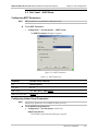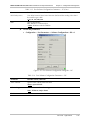
1
RADview/TDM
Element Management System for TDM Applications
FCD-E1LC/FCD-T1LC
© 1994–2004 RAD Data Communications
Publication 357-626-11/04
Contents
Chapter 1. Introduction
1.1 Overview of RADview FCAPS model ........................................................................... 1-1
1.2 Brief Description of the FCD-E1LC and FCD-T1LC devices.......................................... 1-1
1.3 Launching RADview FCD-E1LC /FCD-T1LC................................................................. 1-2
Opening the FCD-E1LC /FCD-T1LC View Window .............................................................. 1-2
Using the Graphical User Interface (GUI)............................................................................... 1-6
LEDs..................................................................................................................................... 1-8
1.4 Port Level Operations ................................................................................................ 1-14
Chapter 2. Fault Configuration
2.1 System Level – Edit Menu ............................................................................................ 2-1
Viewing Sanity Check Errors.................................................................................................. 2-1
2.2 System Level – Agent Menu ......................................................................................... 2-2
Masking Alarms..................................................................................................................... 2-2
Displaying All Active Alarms .................................................................................................. 2-3
Displaying System Level Alarms............................................................................................. 2-4
Clearing FCD Agent Alarms................................................................................................... 2-5
Defining Scope of Alarm Reports........................................................................................... 2-5
Displaying the History Log .................................................................................................... 2-6
Displaying Self-Test Results ................................................................................................... 2-8
2.3 Port Level – Edit Menu ................................................................................................ 2-9
Configuring BERT Parameters................................................................................................ 2-9
Configuring Inband Loop Parameters .................................................................................... 2-9
2.4 Port Level – Agent Menu ........................................................................................... 2-11
Masking Port Alarms ........................................................................................................... 2-11
Clearing the Alarm Buffer.................................................................................................... 2-14
Displaying Port Failures....................................................................................................... 2-14
Running the Diagnostic Tests............................................................................................... 2-15
BERT Counters.................................................................................................................... 2-16
Chapter 3. Configuration Management
3.1 System Level – Edit Menu ............................................................................................ 3-1
Configuring FCD Information ................................................................................................ 3-1
Displaying System Information .............................................................................................. 3-2
Configuring Timeslot Assignment........................................................................................... 3-3
Reading (Uploading) the Agent Configuration........................................................................ 3-6
Updating (Downloading) the Configuration to the Agent........................................................ 3-7
Polling the Agent................................................................................................................... 3-8
Displaying the Agent View .................................................................................................... 3-8
3.2 System Level – Agent Menu ......................................................................................... 3-8
Displaying FCD Information.................................................................................................. 3-8
Setting System Information.................................................................................................. 3-10
Setting the Agent Date and Time......................................................................................... 3-11
Displaying Timeslot Routing Connections ............................................................................ 3-12
Resetting the FCD-E1LC/FCD-T1LC .................................................................................... 3-13
Configuring the Manager List............................................................................................... 3-13
RADview/TDM FCD-E1L/FCD-T1L Installation and Operation Manual
i
Table of Contents
Displaying the Agent View .................................................................................................. 3-14
3.3 Port Level – Edit Menu .............................................................................................. 3-14
Configuring User Information .............................................................................................. 3-14
Configuring Port Parameters................................................................................................ 3-15
3.4 Port Level – Agent Menu ........................................................................................... 3-26
Displaying Port Information................................................................................................. 3-26
Displaying Port Configuration.............................................................................................. 3-27
Configuring Callout Destinations ......................................................................................... 3-38
Chapter 4. Performance Monitoring
4.1 System – Edit Menu ..................................................................................................... 4-1
Polling the Agent................................................................................................................... 4-1
4.2 System – Agent Menu .................................................................................................. 4-1
Displaying G.826 Statistics .................................................................................................... 4-1
4.3 Port – Edit Menu ......................................................................................................... 4-3
4.4 Port – Agent Menu ...................................................................................................... 4-4
Viewing Port Statistics ........................................................................................................... 4-4
Viewing Port Performance Data ............................................................................................ 4-5
Displaying FDL Rx Messages (FCD-T1L only) ....................................................................... 4-10
Chapter 5. Configuring a Typical Application
5.1 Overview..................................................................................................................... 5-1
Application ........................................................................................................................... 5-1
Guidelines for Configuring Typical Application ...................................................................... 5-1
5.2 Configuring FCD-LC Units ........................................................................................... 5-2
Configuring the IP Parameters ............................................................................................... 5-2
Configuring Manager List ...................................................................................................... 5-2
5.3 Configuring TDM Parameters....................................................................................... 5-3
Configuring Line Type........................................................................................................... 5-3
List of Figures
1-1.
1-2.
1-3.
1-4.
1-5.
TDM Nodes on the Net Map................................................................................................. 1-2
FCD-E1L Edit Configuration in Focus ..................................................................................... 1-3
FCD-T1L Edit Configuration in Focus..................................................................................... 1-4
FCD-E1L Agent Configuration in Focus.................................................................................. 1-5
FCD-T1L Agent Configuration in Focus.................................................................................. 1-6
2-1. Sanity Check Error List........................................................................................................... 2-2
2-2. Mask System Alarms Dialog Box ............................................................................................ 2-3
2-3. All Alarms Active List ............................................................................................................. 2-4
2-4. FCD Active List...................................................................................................................... 2-5
2-5. Alarm Report Dialog Box ....................................................................................................... 2-6
2-6. Alarm Buffer List.................................................................................................................... 2-7
2-7. Save File Dialog Box.............................................................................................................. 2-8
2-8. Self-Test Results..................................................................................................................... 2-9
2-9. Manager List.......................................................................................................................... 2-9
2-10. BERT Parameters ............................................................................................................... 2-10
ii
RADview/TDM FCD-E1L/FCD-T1L Installation and Operation Manual
Table of Contents
2-11.
2-12.
2-13.
2-14.
2-15.
2-16.
2-17.
2-18.
Inband Loop Parameters ................................................................................................... 2-11
Port Mask Alarms for FCD-E1L ......................................................................................... 2-12
Port Mask Alarms for FCD-T1L ......................................................................................... 2-13
Port Active Alarm List ........................................................................................................ 2-14
Line Status......................................................................................................................... 2-15
Port Tests – Agent – CH 1.................................................................................................. 2-16
BERT Counters – CH 1 – Agent ......................................................................................... 2-17
BERT Polling Interval ......................................................................................................... 2-18
3-1. System Information ............................................................................................................... 3-1
3-2. FCD Information ................................................................................................................... 3-2
3-3. TS Assignment for FCD-E1L ................................................................................................... 3-3
3-4. TS Assignment for FCD-T1L................................................................................................... 3-3
3-5. Group Connection ................................................................................................................ 3-5
3-6. Read Configuration Message ................................................................................................. 3-6
3-7. Update Configuration Dialog Box .......................................................................................... 3-7
3-8. FCD Information ................................................................................................................... 3-8
3-9. System Information ............................................................................................................. 3-10
3-10. Agent Date & Time............................................................................................................ 3-11
3-11. TS Assignment Window for FCD-E1L................................................................................. 3-12
3-12. TS Assignment Window for FCD-T1L ................................................................................ 3-12
3-13. User Information ............................................................................................................... 3-13
3-14. CONTROL DCE Port Configuration – SP ........................................................................... 3-14
3-15. CONTROL DCE Port Configuration – DP .......................................................................... 3-15
3-16. Port Software Configuration Parameters – Main E1 ............................................................ 3-17
3-17. Port Software Configuration Parameters – Main T1............................................................ 3-19
3-18. Port Software Configuration Dialog Box – CH 1................................................................. 3-22
3-19. Port Software Configuration Dialog Box – CH 2, HS Tab ................................................... 3-23
3-20. Port Software Configuration Dialog Box – CH 2, Ethernet Tab ........................................... 3-24
3-21. Sample Port Information.................................................................................................... 3-25
3-22. Port Software Configuration Dialog Box – SP ..................................................................... 3-26
3-23. Port Software Configuration Dialog Box – DP .................................................................... 3-27
3-24. Port Software Configuration Parameters – Main E1 ............................................................ 3-29
3-25. Port Software Configuration Parameters – Main T1............................................................ 3-32
3-26. Port Software Configuration Dialog Box – CH 1................................................................. 3-35
3-27. Ethernet Parameters Dialog Box – CH 2 ............................................................................ 3-36
3-28. Callout Destinations .......................................................................................................... 3-37
4-1.
4-2.
4-3.
4-4.
4-5.
4-6.
4-7.
4-8.
G.826 Current Data .............................................................................................................. 4-2
Link Current Data.................................................................................................................. 4-2
Link Last Data ....................................................................................................................... 4-3
Port Statistics ........................................................................................................................ 4-4
Polling Interval – E1 – Agent .................................................................................................. 4-5
Current Data ......................................................................................................................... 4-6
Intervals Data ........................................................................................................................ 4-8
FDL Rx Message Dialog Box .................................................................................................. 4-9
RADview/TDM FCD-E1L/FCD-T1L Installation and Operation Manual
iii
Table of Contents
List of Tables
1-1.
1-2.
1-3.
1-4.
1-5.
FCD-E1L LEDs....................................................................................................................... 1-8
System Level Management Options – Edit Mode ................................................................... 1-9
System Level Management Options – Agent Mode .............................................................. 1-10
Port Level Management Options – Edit Mode...................................................................... 1-11
Port Level Management Options – Agent Mode................................................................... 1-11
2-1. FCD Active List...................................................................................................................... 2-4
2-2. FCD Active List...................................................................................................................... 2-5
2-3. Alarm Report Parameters....................................................................................................... 2-6
2-4. Alarm Buffer List.................................................................................................................... 2-7
2-5. Manager List........................................................................................................................ 2-10
2-6. BERT Parameters ................................................................................................................. 2-10
2-7. Inband Loop Parameters ..................................................................................................... 2-11
2-8. Active Alarm List.................................................................................................................. 2-14
2-9. Port Tests ............................................................................................................................ 2-16
2-10. BERT Counters Parameters ................................................................................................ 2-17
3-1. System Information ............................................................................................................... 3-1
3-2. FCD Information Parameters ................................................................................................. 3-2
3-3. FCD Information Parameters ................................................................................................. 3-9
3-4. System Information ............................................................................................................. 3-10
3-5. Agent Date & Time.............................................................................................................. 3-11
3-6. User Information Parameters – SP ....................................................................................... 3-13
3-7. CONTROL DCE Port Configuration Parameters – SP ........................................................... 3-15
3-8. E1 Port Software Configuration Parameters.......................................................................... 3-17
3-9. T1 Port Software Configuration Parameters.......................................................................... 3-20
3-10. CH 1, CH 2 Port Configuration Parameters – HS Tab ........................................................ 3-23
3-11. CH 2 Port Software Configuration Parameters – Ethernet Tab............................................ 3-24
3-12. Port Software Configuration Parameters – SP ..................................................................... 3-26
3-13. Callout Parameters (DP Tab).............................................................................................. 3-27
3-14. E1 Port Software Configuration Parameters........................................................................ 3-30
3-15. T1 Port Software Configuration Parameters........................................................................ 3-32
3-16. CH 1, CH 2 Parameters – HS Tab ..................................................................................... 3-35
3-17. ETH Tab Parameters.......................................................................................................... 3-36
3-18. Call Out Destinations Parameters ...................................................................................... 3-37
4-1.
4-2.
3-3.
3-4.
3-5.
iv
Port Statistics ......................................................................................................................... 4-4
Polling Interval Parameters .................................................................................................... 4-5
Port Performance Current Data ............................................................................................. 4-7
Port Performance Interval Data (Additional Parameters)......................................................... 4-8
Port FDL Rx Message............................................................................................................. 4-9
RADview/TDM FCD-E1L/FCD-T1L Installation and Operation Manual
Chapter 1
Introduction
This chapter provides an overview of the FCD-E1LC/FCD-T1LC devices and the
RADview FCD-E1LC/FCD-T1LC user interface.
1.1 Overview of RADview FCAPS model
RADview provides a complete solution for monitoring and controlling FCD–E1LC
and FCD-T1LC devices. The RADview solutions conform to ITU-T
Telecommunication Management Network (TMN) recommendations for SNMP
management systems, known as the FCAPS model:
•
Fault management – detects and correlates fault in network devices, isolates
faults and initiates recovery actions.
•
Configuration management – tracks configuration changes, configures, installs
and distributes software and configuration files across the network.
•
Accounting management – collects accounting data and generates network
usage reports.
•
Performance management – continuously monitors network performance
(QoS, CoS) and resource allocation.
•
Security management – controls and restricts access to network resources.
1.2 Brief Description of the FCD-E1LC and FCD-T1LC
devices
The FCD-E1LC and FCD-T1LC are managed single- or dual-port access units for
business applications that integrate voice and data traffic over E1 (2.048 Mbps) /
T1 (1.544 Mbps) and fractional E1/T1 services. FCD-E1LC /FCD-T1LC can be
used as a rate and interface converter or as an integrating E1/T1 multiplexer for
Fractional E1/T1 services. Data port rates for FCD-E1LC are selectable for any
multiple of 64 kbps, up to 2048 kbps. Data port rates for FCD-T1LC are selectable
for any multiple of 64 kbps, up to 1536 kbps. User data of each port is placed into
an E1/T1 frame, using only the required number of timeslots.
FCD-E1LC /FCD-T1LC is available in a single- and dual-channel versions.
Note
In this manual, the generic term CH is used when the information is applicable both
to CH 1 and CH 2, as well as to a single-channel version. When information is
applicable to a specific channel (CH 1 or CH 2), this will be explicitly specified.
Brief Description of the FCD-E1LC and FCD-T1LC devices
1-1
RADview/TDM FCD-E1LC/FCD-T1LC User’s Manual
Chapter 1 Introduction
1.3 Launching RADview FCD-E1LC /FCD-T1LC
Opening the FCD-E1LC /FCD-T1LC View Window
A TDM Unit View window exists for each unit node on the map.
Figure 1-1. FCD-E1/T1-LC Devices on SNMP Map
To open the FCD-E1LC /FCD-T1LC window:
•
Double-click on an FCD-E1LC /FCD-T1LC icon in the net map.
The FCD-E1LC /FCD-T1LC Edit Configuration Mode appears.
1-2
Launching RADview FCD-E1LC /FCD-T1LC
RADview/TDM FCD-E1LC/FCD-T1LC User’s Manual
Chapter 1 Introduction
Figure 1-2. FCD-E1LC Edit Configuration in Focus
Figure 1-3. FCD-T1LC Edit Configuration in Focus
Launching RADview FCD-E1LC /FCD-T1LC
1-3
RADview/TDM FCD-E1LC/FCD-T1LC User’s Manual
Chapter 1 Introduction
Figure 1-4. FCD-E1LC Agent Configuration in Focus
Figure 1-5. FCD-T1LC Agent Configuration in Focus
1-4
Launching RADview FCD-E1LC /FCD-T1LC
RADview/TDM FCD-E1LC/FCD-T1LC User’s Manual
Chapter 1 Introduction
Using the Graphical User Interface (GUI)
The FCD-E1LC /FCD-T1LC Level window provides a dynamically updated
graphical representation of the front and rear panel, allowing you to monitor and
manage FCD-E1LC /FCD-T1LC operations. The view includes port interfaces and
their operational and communication status.
Status Bar
The Status Bar indicates if FCD-E1LC /FCD-T1LC is Connected or Disconnected.
Menu Bar
The Edit/Agent mode menu bars include any of the following pull-down menus:
Configuration, Fault, Diagnostics, Statistics, Window, Options and Help. Menu
contents differ between Edit and Agent modes, and differ when ports are selected.
Toolbar
The following shortcut keys are available on the toolbar:
current
FCD-E1LC /FCD-T1LC Info – Display status and configuration of
FCD-E1LC /FCD-T1LC .
TS Assignment – View the actual timeslot assignments for all ports.
Poll Agent – Causes the NMS to poll the agent.
Software Configuration – access the port configuration dialog box.
Reset – Resets the FCD-E1LC /FCD-T1LC device.
Agent/Edit Modes
Two views of the agent are displayed in the FCD-E1LC /FCD-T1LC view window:
•
The top view, Edit Configuration Mode, corresponds to a configuration that is
stored in the management station. In the Edit Configuration mode, you can
change configuration settings.
•
The bottom view, Agent Mode, corresponds to the agent unit as a whole, and
to the current configuration of the selected agent. In the Agent mode, you can
monitor the configurations and performance of the FCD-E1LC /FCD-T1LC
and its ports.
One mode may be selected at any given time. The selected (active) mode is
surrounded by a light blue border.
To display the Agent mode:
•
From the Window menu, select Agent View.
To toggle between the Agent mode and the Edit Configuration mode:
•
Click on the hub which is not currently selected.
Launching RADview FCD-E1LC /FCD-T1LC
1-5
RADview/TDM FCD-E1LC/FCD-T1LC User’s Manual
Chapter 1 Introduction
Edit Configuration Mode
The Edit Configuration mode (top) is always displayed in the FCD-E1LC /FCDT1LC Level window. The Edit Configuration mode is used to design configuration
modifications, without interfering with ongoing FCD-E1LC /FCD-T1LC activities.
Any Edit Configuration can be downloaded to the FCD-E1LC /FCD-T1LC unit.
The contents of the window Title Bar and Menu Bar depend on the selected
view.
If the Edit Configuration mode is selected, the following appears:
•
Window Title – The window title identifies the selected mode - E (Edit), the
selected configuration (1 to 10), the FCD-E1LC /FCD-T1LC name, and its
current status, Connected or Disconnected. It is possible to prepare a
configuration without being connected to the agent.
•
Window Menu Bar – The Edit Configuration mode menu bar includes the
Configuration, Fault, Window and Help pull-down menus. Menu contents
differ when cards or ports are selected.
Agent Mode
The Agent mode (bottom) displays the current parameters of the agent currently
operating. This data includes system information (hardware and software),
interface information, and channel configuration values. The data displayed in the
Agent mode may be used for comparison and analysis when preparing a
configuration in the Edit Configuration mode.
Diagnostic operations can also be performed at the management station from the
Agent mode. In addition, event and active alarm messages are accessed here.
If the Agent mode is selected, the following appears:
1-6
•
Window Title – The window title identifies the selected mode - A (Agent), the
selected configuration (1 to 10), the FCD-E1LC /FCD-T1LC name, and its
current status, Connected or Disconnected.
•
Window Menu Bar – The Agent mode menu bar includes the Configuration,
Statistics, Fault, Window, Options and Help pull-down menus. Menu
contents differ when ports are selected.
Launching RADview FCD-E1LC /FCD-T1LC
RADview/TDM FCD-E1LC/FCD-T1LC User’s Manual
Chapter 1 Introduction
LEDs
Table 1-1 describes the FCD-E1LC LEDs on the front panel.
Table 1-1. FCD-E1LC LEDs
LED Name
Color
Remarks
PWR
Green
On: When power is on (always in NMS)
Off: When power is off
TST
Yellow
Indicates that a test is running on one of the ports
ALM
Red
On: When there is a minor alarm
Blinking: When there is a major alarm
E1: LOC (MAIN)
(FCD-E1LC only)
Red
Indicates Local Sync Loss alarm on MAIN link
T1: RED (MAIN)
(FCD-T1LC only)
Red
Indicates Red alarm on MAIN link
E1: REM (MAIN)
(FCD-E1LC only)
Red
On: When there is a Remote Sync Loss alarm on the Main link
T1: YEL (MAIN)
(FCD-T1LC only)
Yellow
On: when there is a Yellow Alarm on the Main link
E1: LOC (SUB)
(FCD-E1LC only)
Red
Indicates Local Sync Loss alarm on SUB link
T1: RED (SUB)
(FCD-T1LC only)
Red
Indicates Red alarm on SUB link
E1: REM (SUB)
(FCD-E1LC only)
Red
Indicates Remote Sync Loss alarm on SUB link
T1: YEL (SUB)
(FCD-T1LC only)
Yellow
Indicates Yellow alarm on SUB link
Launching RADview FCD-E1LC /FCD-T1LC
1-7
RADview/TDM FCD-E1LC/FCD-T1LC User’s Manual
Chapter 1 Introduction
1.4 System Level Operations
Table 1-2 lists the system management options for FCD-E1LC /FCD-T1LC possible
in the Edit mode.
Table 1-2. System Level Management Options – Edit Mode
Tasks – Configuration
Dialog Box and Parameter Location
Path
Configuring FCD information
FCD information dialog box
(See Configuring FCD Information)
Configuration
FCD Info…
Displaying system
information
System Information dialog box
(See Displaying System Information)
Configuration
System Info…
Configuring TS Assignment
TS Assignment dialog box
(See Configuring Timeslot Assignment)
Configuration
TS Assignment…
Read
See Reading (Uploading) the Agent
Configuration
Configuration
Read …
Tasks – Fault
Dialog Box and Parameter Location
Path
Update
See Updating (Downloading) the
Configuration to the Agent
Configuration
Update …
Poll Agent
See Polling the Agent
Configuration
Poll Agent
Tasks – Fault
Dialog Box and Parameter Location
Path
Displaying Sanity Check
Errors
Sanity Check Errors List
(See Viewing Sanity Check Errors)
Fault
Sanity Check Errors…
Tasks – Window
Dialog Box and Parameter Location
Path
Displaying Edit/Agent View
See Displaying Agent View
Window
Agent View
1-8
System Level Operations
RADview/TDM FCD-E1LC/FCD-T1LC User’s Manual
Chapter 1 Introduction
Table 1-3 lists the management options for FCD-E1LC /FCD-T1LC possible in the
Agent mode.
Table 1-3. System Level Management Options – Agent Mode
Tasks – Fault
Dialog Box and Parameter Location
Path
Masking Alarms
Mask System Alarms dialog box
See Masking Alarms
Fault
Alarms
Mask…
Displaying all active alarms
All Active Alarm List
(See Displaying All Active Alarms)
Fault
Alarms
List
All…
Displaying active alarms on
the system level
Active System-Level Alarm List
(See Displaying System Level Alarms)
Fault
Alarms
List
System level…
Clearing active alarms
See Clearing FCD-LC Agent Alarms
Fault
Alarms
Clear
Clearing all alarms
See Clearing FCD-LC Agent Alarms
Fault
Alarms
Clear All
Defining Scope of Alarm
Reports
Alarm Report dialog box
See Defining Scope of Alarm Reports
Fault
Alarms
Report…
Displaying History Log
Alarm Buffer List
See Displaying the History Log
Fault
History Log
List…
Clearing History Log
Alarm Buffer List
See Displaying the History Log
Fault
History Log
Clear
Displaying Self Test Results
Self Test Results
See Displaying Self-Test Results
Fault
Self Test…
Tasks – Configuration
Dialog Box and Parameter Location
Path
Displaying FCD information
FCD Information dialog box
See Displaying FCD Information
Configuration
FCD Info…
Setting system information
System Information dialog box
See Setting System Information
Configuration
System Info…
Setting Date and Time
Agent Date & Time dialog box
See Setting the Agent Date and Time
Configuration
Date & Time…
Displaying TS Assignment
TS Assignment Window
See Displaying Timeslot Routing Connections
Configuration
TS Assignment…
System Level Operations
1-9
RADview/TDM FCD-E1LC/FCD-T1LC User’s Manual
Chapter 1 Introduction
Table 1-3. System Level Management Options – Agent Mode (Cont.)
Reset
See Resetting the FCD
Configuration
Reset
Tasks – Statistics
Dialog Box and Parameter Location
Path
Displaying G.826 Data
G.826 Current Data
See Displaying G.826 Statistics
Statistics
G.826 Data
Tasks – Options
Dialog Box and Parameter Location
Path
Configuring the Manager List
Manager List
(See Configuring the Manager List)
Options
Manager List…
1.5 Port Level Operations
Note
Port level operations are available only when a port is selected (in focus).
Table 1-4 lists the port level management options for FCD-E1LC /FCD-T1LC
available in the Edit mode.
Table 1-4. Port Level Management Options – Edit Mode
Tasks – Configuration
Dialog Box and Parameter Location
Path
Software Configuration
(Main E1, Main T1, CH 1,
CH 2, SP)
Port Software Configuration dialog box
See Configuring Port Parameters
Configuration
Port Parameters
Software Configuration…
Configuring BERT
Parameters
BERT Parameters dialog box
See Configuring BERT Parameters
Configuration
Port Parameters
BERT Param…
Configuring Inband Loop
Parameters
Inband Loop Parameters dialog box
See Configuring Inband Loop Parameters
Configuration
Port Parameters
Inband Loop Param…
Configuring User
Information
User Information dialog box
See Configuring User Information
Configuration
User Info…
Note
Port level operations are available only when a port is selected (in focus).
Table 1-5 lists the port level management options for FCD-E1LC /FCD-T1LC
available in the Agent mode.
1-10
Port Level Operations
RADview/TDM FCD-E1LC/FCD-T1LC User’s Manual
Chapter 1 Introduction
Table 1-5. Port Level Management Options – Agent Mode
Tasks – Fault
(CH and E1/T1 only)
Dialog Box and Parameter Location
Path
Mask Alarms
Port Mask Alarms
See Masking Port Alarms
Fault
Alarms
Mask…
List all alarms
Port Active Alarm List
See Displaying Port Active Alarms List
Fault
Alarms
List…
Clear alarms
See Clearing the Alarm Buffer
Fault
Alarms
Clear
Displaying E1 Link Status
Line Status
See Displaying Port Failures
Fault
Line Status…
Tasks – Configuration
Dialog Box and Parameter Location
Path
Displaying Port Information
Port Information dialog box
See Displaying Port Information
Configuration
Port Parameters
Port Information…
Displaying Port
Configuration
(for SP, E1/T1, CH)
System Information dialog box
See Displaying Port Configuration
Configuration
Port Parameters
Software Configuration…
Configuring Callout
Destinations
(for SP only)
Call Out Destinations dialog box
See Configuring Callout Destinations
Configuration
Port Parameters
Call Out Destinations
Bert Counters
Bert Counters dialog box
(See BERT Counters)
Configuration
BERT Param…
Inband Loop Parameters
Inband Loop Parameters dialog box
(See Configuring Inband Loop Parameters)
Configuration
Inband Loop Param…
Tasks – Diagnostics
Dialog Box and Parameter Location
Path
Running Diagnostic Tests
Port Tests dialog box
(See Running the Diagnostic Tests)
Diagnostics
Test…
BERT Counters (CH1 only)
BERT Counters dialog box
(See BERT Counters)
Diagnostics
BERT Counters…
Tasks – Statistics
Dialog Box and Parameter Location
Path
Polling Interval – E1/T1 – Agent
(See Polling Interval)
Statistics
Port Performance
Polling Interval…
(for CH and E1/T1 only)
(for E1/T1 only)
Set Polling interval
Port Level Operations
1-11
RADview/TDM FCD-E1LC/FCD-T1LC User’s Manual
Chapter 1 Introduction
Table 1-5. Port Level Management Options – Agent Mode (Cont.)
View Current Data table and
graph
Current Data
(See Displaying Current Data Table and
Graph)
Statistics
Port Performance
Current Data…
View Interval Data table and
graph
Interval Data
(See Displaying Interval Table and Graph)
Statistics
Port Parameters
Interval Data…
Resettng Statistics
See Reset Statisitics
Statistics
Port Performance
Reset Statistics…
Viewing FDL Rx messages
(FCD-T1LC only)
FDL Rx Message dialog box (see Displaying
FDL Rx Messages (FCD-T1LC only)
Statistics
FDL Message
Rx…
1-12
Port Level Operations
Chapter 2
Fault Configuration
2.1 System Level – Edit Menu
Viewing Sanity Check Errors
To view the results of the last agent sanity check:
1. Fault > Sanity Check Errors...
If the Edit Configuration does not contain error(s) or warning(s), the
message No Sanity Errors appears.
2. Click <OK> to continue.
If the sanity check detects errors or warning situations, the Sanity Check
Errors List and/or Warning List appears on the screen. Errors appear first in
the list, followed by warnings. If necessary, click the scroll bar and scroll
arrows to view the additional entries.
System Level – Edit Menu
2-1
Chapter 2 Fault Configuration
RADview/TDM FCD-E1LC/FCD-T1LC Installation and Operation Manual
Figure 2-1. Sanity Check Error List
2.2 System Level – Agent Menu
Masking Alarms
The Mask... command displays a list of active unmasked alarms for the selected
FCD-LC, including system (agent) and port alarms.
Note
Masking active alarms will also mask them from the History Log.
To view all active FCD-LC alarms:
1. Fault > Alarms > Mask…
The Mask System Alarms dialog box appears.
2. Select the alarms you want to mask and click <Set>.
2-2
System Level – Agent Menu
RADview/TDM FCD-E1LC/FCD-T1LC Installation and Operation Manual
Chapter 2 Fault Configuration
Figure 2-2. Mask System Alarms Dialog Box
Displaying All Active Alarms
The List>All... command displays a list of active unmasked alarms for the selected
FCD-LC, including system (agent) and port alarms.
To view all active FCD-LC alarms:
•
Fault > Alarms > List > All…
The FCD All Active Alarm List appears.
The FCD All Active Alarm List displays active system and port alarms. If the list is
long, you can click the scroll bar or scroll arrows to display more entries.
Table 2-1. FCD-LC Active List
Parameter
Possible Values / Remarks
Code
Code which indicates a certain alarm description
Port
Port in which the alarm originated.
Description
Description of the alarm
Status
State of the alarm
Minor , Major
System Level – Agent Menu
2-3
Chapter 2 Fault Configuration
RADview/TDM FCD-E1LC/FCD-T1LC Installation and Operation Manual
Figure 2-3. All Alarms Active List
Displaying System Level Alarms
The List>System Level command displays a list of active unmasked alarms for the
selected FCD-LC only.
To view all active FCD-LC system level alarms:
•
Fault > Alarms > List > System Level…
The FCD Active Alarm List appears.
The FCD Active List displays active system alarms. If the list is long, you can click
the scroll bar or scroll arrows to display more entries.
Table 2-2. FCD Active Alarm List
Parameter
Possible Values / Remarks
Code
Code which indicates a certain alarm description
Description
Description of the alarm
Status
State of the alarm
Minor , Major
2-4
System Level – Agent Menu
RADview/TDM FCD-E1LC/FCD-T1LC Installation and Operation Manual
Chapter 2 Fault Configuration
Figure 2-4. FCD Active Alarm List
Clearing FCD-LC Agent Alarms
You can clear only system level alarms or all active alarms from the system
database.
To clear active system level alarms:
•
Fault > Alarms > Clear.
The system does not request confirmation for this operation.
To clear all active alarms:
•
Fault > Alarms > Clear All.
The system does not request confirmation for this operation.
Defining Scope of Alarm Reports
Using the Reports command, you can define the severity of alarm reports received
at the network management station.
To define an alarm report:
1. Fault > Alarms > Report…
The Alarm Report dialog box appears where you can set the severity
criteria for reporting alarms.
2. Set the severity levels in each field.
3. Click <Set>.
System Level – Agent Menu
2-5
Chapter 2 Fault Configuration
RADview/TDM FCD-E1LC/FCD-T1LC Installation and Operation Manual
Figure 2-5. Alarm Report Dialog Box
Table 2-3. Alarm Report Parameters
Parameter
Possible Values / Remarks
Trap
Alarm On Severity:
Minimum level of severity required for sending a trap to the network
management station
No Report, Minor, Major
Alarm Off Severity:
Maximum level of severity allowed for a trap not to be sent to the network
management station
No Report, Minor, Major
Displaying the History Log
The history log contains all the alarms listed in FCD-LC alarm buffer in
chronological order of occurrence. The buffer's capacity is 256 alarms. You may
view and print its contents.
To display all the alarms in FCD-LC history alarm buffer:
•
Fault > History Log > List...
The Alarm Buffer List appears.
2-6
System Level – Agent Menu
RADview/TDM FCD-E1LC/FCD-T1LC Installation and Operation Manual
Chapter 2 Fault Configuration
Figure 2-6. Alarm Buffer List
The Alarm Buffer List displays all the unmasked recorded alarms from
system, card and port levels since the last time the log was recorded. If the
list is long, you can click the scroll bar or scroll arrows to display more
entries.
Table 2-4. Alarm Buffer List
Parameter
Possible Values / Remarks
Code
Code which indicates a certain alarm description
Port
Port number in which the alarm originated. This parameter is applicable only for
port alarms
Description
Description of the alarm
Status
The status of the alarm
Major, Minor, Off
Date
Date when the alarm occurred
Time
Time when the alarm occurred
To clear all the alarms from FCD-LC alarm buffer:
•
Fault > History Log > Clear
OR
•
Click <Clear>.
The system does not request confirmation for this operation.
To save the list:
1. Click <Save to File…>
The Save File Dialog Box appears.
System Level – Agent Menu
2-7
Chapter 2 Fault Configuration
RADview/TDM FCD-E1LC/FCD-T1LC Installation and Operation Manual
2. Enter filename and select type of file (PDF or HTML).
3. Select location to save the file and click <Save>.
Figure 2-7. Save File Dialog Box
To print the list:
•
Click <Print…>
The printer dialog box appears.
Displaying Self-Test Results
When powered, the FCD-LC runs a self-test to detect hardware failures and to
provide circuit-level diagnostics data. The Self Test command displays the results
of the selected FCD-LC self-tests.
To display FCD-LC self-test results:
•
Fault > Self Test...
The Self Test Results dialog box appears.
This dialog box lists all possible detectable agent failures and the status of each
failure. A failure in the parameter is indicated by “On”. No failure detected is
indicated by “—“.
Figure 2-8. Self-Test Results
2-8
System Level – Agent Menu
RADview/TDM FCD-E1LC/FCD-T1LC Installation and Operation Manual
Chapter 2 Fault Configuration
2.3 Port Level – Edit Menu
Configuring BERT Parameters
Note
BERT parameters are available for Main ports only.
To set BERT Parameters:
1. Configuration > Port Parameters > BERT Param...
The BERT Parameters dialog box appears.
Figure 2-9. BERT Parameters
Table 2-5. BERT Parameters
Parameter
Possible Values / Remarks
Port
Main E1, Main T1
Port Type
E1, T1
BERT Pattern
511, 2047, 2E15-1, QRSS, 2E23-1
BERT Error Inject Rate
No Error, 1
Configuring Inband Loop Parameters
Note
Inband Loop parameters are available for Main port only.
To set Inband Loop parameters:
•
Configuration > Port Parameters followed by
Inband Loop Param…
The Inband Loop Parameters dialog box appears.
Port Level – Edit Menu
2-9
Chapter 2 Fault Configuration
RADview/TDM FCD-E1LC/FCD-T1LC Installation and Operation Manual
Figure 2-10. Inband Loop Parameters
Table 2-6. Inband Loop Parameters
Parameter
Possible Values / Notes
Port
Main E1, Main T1
Port Type
E1, T1
Inband Loop
Pattern Configuration
RDL Loop, User Configured
Activate Pattern (bin)
Binary String of up to 8 bits (LSB is rightmost bit)
Only “1” or “0” digits will be allowed.
Default: 0
This field is enabled only when Pattern Configuration=User Configured
Dectivate Pattern (bin)
Binary String of up to 8 bits (LSB is rightmost bit)
Only “1” or “0” digits will be allowed.
Default: 0
This field is enabled only when Pattern Configuration=User Configured
2-10
Port Level – Edit Menu
RADview/TDM FCD-E1LC/FCD-T1LC Installation and Operation Manual
Chapter 2 Fault Configuration
2.4 Port Level – Agent Menu
Masking Port Alarms
Masking alarms changes the alarm status of the FCD-LC. If you want the change to
take place immediately, you must clear the current alarms, otherwise, the effect will
occur only after the next automatic system poll.
To mask alarms:
1. Fault > Alarms > Mask…
2. For each alarm you want to mask, check the appropriate checkbox.
Note
Choice of alarms for masking depends on selected port.
Figure 2-11. Port Mask Alarms
Displaying Port Active Alarms List
To list port active alarms:
•
Fault > Alarms List…
The Port Active Alarms List appears.
Port Level – Agent Menu
2-11
RADview/TDM FCD-E1LC/FCD-T1LC Installation and Operation Manual
Chapter 2 Fault Configuration
Figure 2-12. Port Active Alarm List
Table 2-7. Active Alarm List
Parameter
Possible Values / Notes
Port
MAIN E1, MAIN T1, SUB E1, SUB T1, CH 1, CH 2
Port Type
E1, T1, HS
Code
Alarm code
Description
Text description
Status
Minor, Major
To save the list:
1. Click <Save to File…>
The Save to File Dialog Box appears (Figure 2-7).
2. Enter filename and select type of file (PDF or HTML).
3. Select location to save the file and click <Save>.
2-12
Port Level – Agent Menu
RADview/TDM FCD-E1LC/FCD-T1LC Installation and Operation Manual
Chapter 2 Fault Configuration
To print the list:
•
Click <Print…>
The printer dialog box appears.
Clearing the Alarm Buffer
To clear alarms:
•
From the Fault menu, select Alarms followed by Clear.
The alarms are cleared from the buffer.
Displaying Port Failures
The Line Status command allows you to view failures, if any, in the selected port.
Note
Line Status is available for E1/T1 Main and Sub ports only.
To display port failures:
•
From the Fault menu, select Line Status.
The Line Status dialog box appears.
Figure 2-13. Line Status
The dialog box lists all possible detectable port failures and the status of each
failure. The possible failures depend on the type of port. The available status
options are:
On
Failure exists.
—
No failure.
Running the Diagnostic Tests
To enter the diagnostic test function:
•
Diagnostics > Test...
The Port Tests dialog box appears. A sample Port Tests dialog box is shown
for a CH 1 port.
Port Level – Agent Menu
2-13
RADview/TDM FCD-E1LC/FCD-T1LC Installation and Operation Manual
Chapter 2 Fault Configuration
Figure 2-14. Port Tests – Agent – CH 1
The Port Tests dialog box contains the port and port type identification at the top
and two main functional sections, Status and Activate.
Table 2-8. Port Tests
Parameter
Possible Values / Remarks
Port
Selected port
MAIN E1, MAIN T1, SUB E1, SUB T1, CH 1, CH 2
Port Type
Type of port
E1, T1, HS
The Status section shows the current testing status at the selected port. In addition,
you can stop a currently running test.
•
The Tests column lists the possible tests for the selected port and the status of
each test. The status can be Active or —(not active).
For CH 1 port, BERT testing status is also included. BERT Counter shows
the number of bit errors detected during the BERT test.
To activate/stop tests:
•
Select appropriate command from the drop down list box and click <Apply>.
The agent stops and/or starts the selected tests accordingly.
2-14
Port Level – Agent Menu
RADview/TDM FCD-E1LC/FCD-T1LC Installation and Operation Manual
Chapter 2 Fault Configuration
BERT Counters
Note
• BERT parameters are available for Main port only.
• In order to see the BERT counters, BERT test must running. Start (activate) BERT
testing from the Port Test Dialog Box.
To view the BERT counters:
•
Diagnostics > BERT Counters…
The BERT Counters Dialog Box appears.
Figure 2-15. BERT Counters – CH 1 – Agent
Port Level – Agent Menu
2-15
RADview/TDM FCD-E1LC/FCD-T1LC Installation and Operation Manual
Chapter 2 Fault Configuration
Table 2-9. BERT Counters Parameters
Parameter
Possible Values / Remarks
Port
Main E1, Main T1
Port Type
E1, T1
BERT Pattern
BER test pattern
511, 2047, 2E15-1, QRSS
BERT Error Inject Rate
(10E-)
Rate of BERT injection
No Error, 1
Tx Inband Loop
On, Off
Sync Status
Sync, Sync Loss
BERT Counters
Run Time (sec)
Indicates how much time (seconds) passed since BERT started to run
Errored Seconds
How many Errored Seconds were detected since BERT started to run
Sync Loss Events
How many times Sync Loss was detected since BERT started to run
Error Bits
How many Error Bits were detected since BERT started to run
Inject Error Command
[Stop]
Stops injection of BERT errors.
[Continuously]
Continously injects bit errors
[Single]
Injects one error
[Polling]
Clicking <Polling> opens BERT Polling Interval dialog box (Figure 2-16).
[Clear Error Bits]
Resets error bit counter to zero.
To Inject Errors while testing:
•
Click <Continuously> or <Single> (only one error is injected)
To stop Inject Errors while testing:
•
Click <Stop>.
To clear the Error Bits:
•
Click <Clear Error Bits>.
The error bits counter is reset to zero.
To set the BERT Polling Interval:
1. Click <Polling...>
The BERT Polling Interval dialog box appears (Figure 2-16).
2. Set the polling interval (10, 20, 30.,..,180 seconds) by choosing a value from
the drop-down list box.
3. Click <Set>.
2-16
Port Level – Agent Menu
RADview/TDM FCD-E1LC/FCD-T1LC Installation and Operation Manual
Chapter 2 Fault Configuration
Figure 2-16. BERT Polling Interval
To set BERT TSs:
1. Click <BERT TS...>
The BERT TSs dialog box appears (Figure 2-17).
2. Check the desired TSs.
3. Click <Close>.
Figure 2-17. BERT TSs
Port Level – Agent Menu
2-17
Chapter 2 Fault Configuration
2-18
Port Level – Agent Menu
RADview/TDM FCD-E1LC/FCD-T1LC Installation and Operation Manual
Chapter 3
Configuration Management
3.1 System Level – Edit Menu
Configuring FCD-LC Information
To set FCD-LC information:
•
Configuration > FCD Info…
The FCD-LC Information dialog box appears.
Figure 3-1. FCD Information
Table 3-1. FCD Information Parameters
Parameter
Possible Values / Notes
Type
FCD-E1LC/FCD-T1LC
Master Clock Source
Type
Internal, Rx Clock
Port
For FCD-E1LC: NA, MAIN E1, SUB E1, CH 1, CH 2
For FCD-T1LC: NA, MAIN T1, SUB T1, CH 1, CH 2
Note: This field is relevant only when Type=Rx Clock
Fallback Clock Source
Type
None, Rx Clock
Note: If Master Clock Source Type=Internal, the Type=None.
Port
For FCD-E1LC: MAIN E1, SUB E1, CH 1, CH 2
For FCD-T1LC: MAIN T1, SUB T1, CH 1, CH 2
System Level – Edit Menu
3-1
Chapter 3 Configuration Management
Note
RADview/TDM FCD-E1LC/FCD-T1LC Installation and Operation Manual
1. If Master/Fallback Type is Rx Clock
AND
Selected port is CH
AND
Line Type IS NOT Unframed, configure the CH as:
• Rate > 0
• Clock Mode = DTE2
2. It is recommended to select CH as Rx Clock for Master Clock rather than for
Fallback Clock (otherwise, a warning is issued upon Update operation).
Displaying System Information
The System Information command enables you to display information about the
system.
To display System Information:
•
Configuration > System Info…
The System Information dialog box appears.
Figure 3-2. System Information
Table 3-2. System Information
Parameter
Possible Values / Notes
Description
SW and HW versions
Name
FCD-E1LC/FCD-T1LC
Contact
User specified
Location
User specified
3-2
System Level – Edit Menu
RADview/TDM FCD-E1LC/FCD-T1LC Installation and Operation Manual
Chapter 3 Configuration Management
Configuring Timeslot Assignment
The TS Assignment command allows you to program the routing of timeslots. A
complete description of the TS assignment function is discussed on the following
pages.
Timeslot Routing
The FCD-E1LC/FCD-T1LC allows you to program the routing of the individual
timeslots.
To configure TS Assignments:
•
Configuration > TS Assignment...
Or
•
Click the TS button on the toolbar
.
The TS Assignment window appears.
Figure 3-3. TS Assignment for FCD-E1LC
Figure 3-4. TS Assignment for FCD-T1LC
System Level – Edit Menu
3-3
Chapter 3 Configuration Management
RADview/TDM FCD-E1LC/FCD-T1LC Installation and Operation Manual
A rectangular grid displays the timeslot assignments. There are 31 timeslots
for FCD-E1LC and 24 timeslots for FCD-T1LC. Each row and each column
represents the possible connections of a specific port.
Colors, letters and guides indicate information about the timeslots and ports
represented in the grid. Their meanings are described in the following pages.
TS Color Codes
Since each TS has only one type and can be connected to only one port, each TS
column can have only one cell with a letter inside. Both connection cells and port
indicator cells use color codes to relay connection information.
Green + number
TS in this port is connected and is not being used for
Management
Gray + number
TS in this port is available for connection, but currently has
no TS connection
Gray empty
Cell's port has no current TS connections but can be TS
connected
Blue + number
TS in this port has no connections and cannot be TS
connected
Blue empty
Cell's port has a TS connection
Yellow + letter
Cell's port has at valid TS connection of type indicated by
letter
Red + number
There is an invalid connection
White + number
TSs in this port is connected and being used for
Management
White empty
Cell's port is being used for Management
Port Name Color Codes
Green
All of the port's connectable TS connections are connected
Gray
None of the port's connectable TSs are being used
Red
This occurs when one of the port's cells is red
Yellow
Some of the TSs are connected
Creating TS Connections
You can create a new TS connection only on gray cells (cells with connectable
TSs).
To create a new TS connection:
•
Click an empty gray cell and click <Data> button.
The cell becomes yellow and the Data connection is indicated by the letter
D in the cell.
3-4
System Level – Edit Menu
RADview/TDM FCD-E1LC/FCD-T1LC Installation and Operation Manual
Chapter 3 Configuration Management
To connect a group of consecutive TS of the main E1/T1 port to the data
channel (CH 1, CH 2):
•
Click <Group>.
The following dialog box appears.
Figure 3-5. Group Connection
•
To connect all connectable TSs to the channel, select <All>.
All connectable TSs are connected to the channel. Their cells become
yellow and the Data connections are indicated by the letter D.
•
To connect a group of consecutive TS to the data channel, select
<Sequence>. In the bottom part of the dialog box, define the number of
consecutive TS to be connected and the number of the first TS to be
connected.
The cells of the defined TS become yellow and the Data connections are
indicated by the letter D.
Notes
• If TS16 selected for management is within the sequence, it will be skipped.
• If the rate set for any of the channels does not match its FIFO Size (selected in
Port Info> SW Configuration), a warning message box is displayed for the
appropriate channel. Click <OK> to close the message box and change the
FIFO Size of the problematic CH to a matching value.
• If the new data overwrites the existing connections, the latter will be
disconnected.
• If you defined too many timeslots to be connected, the following message box
will be displayed: "'No. of TS' is too big. Max. possible TSs will be connected".
When you click OK, only timeslots with numbers higher that Start TS will be
connected.
Disconnecting TS Connections
To disconnect a TS connection in a cell:
•
Click the connected cell and click <Disconnect>.
The TSs cell becomes gray.
System Level – Edit Menu
3-5
Chapter 3 Configuration Management
RADview/TDM FCD-E1LC/FCD-T1LC Installation and Operation Manual
Reset All
To reset all TS connections on the grid:
1. Ensure that no TS connection cell is selected.
2. Click <Reset All>.
The message, “Removing TS connections” appears.
3. Click <OK> to continue.
All existing TS connections in the port are deleted.
Reading (Uploading) the Agent Configuration
The Read command allows you to upload the current FCD-LC agent configuration
to the Edit Configuration. After the Read operation, the Edit Configuration is
identical to the Agent Configuration. The uploaded configuration is automatically
stored in the management station.
Note
Read will be enabled only if there is communication with the agent.
To upload the configuration from the agent:
1. Configuration > Read.
The message, 'Reading operation will replace Edit Configuration', appears.
2. Click <OK> to confirm the operation.
Figure 3-6. Read Configuration Message
Updating (Downloading) the Configuration to the Agent
After editing the FCD-E1LC/FCD-T1LC configuration, you can download the
information to the FCD-LC Agent.
Notes
• Update is available only when there is communication with the agent.
• If tests are currently active (except Rx Inband), FCD-LC sends the following
message: “UPDATE CANNOT BE PERFORMED. Stop tests.”
To download configuration modifications to the agent:
1. Configuration > Update.
The system will perform a Sanity Check, and if passed, the Update
Configuration Window appears displaying the message: “Update
operation will replace Agent’s configuration”.
2. Click <OK> to confirm Update.
3-6
System Level – Edit Menu
RADview/TDM FCD-E1LC/FCD-T1LC Installation and Operation Manual
Chapter 3 Configuration Management
The new configuration is immediately downloaded to the FCD-LC.
Note
If communication problems occur during the update process, the message “Timeout
– Update result was not received” appears.
If tests are running, the message “Update cannot be performed! Stop Tests/s!”
appears.
Figure 3-7. Update Configuration Dialog Box
Note
In the event that the sanity check found errors, the message “Sanity Check Errors”
appears and update cannot be performed.
If the sanity check failed due to warnings (not errors), a message box appears
indicating that there were warnings.
The message box has the following options:
Cancel (leave without updating/seeing the warnings),
View Warnings (see warnings that were issued during Sanity Check),
Close (close message box without updating the configuration),
Confirm Update (update the configuration with the warnings at any stage).
Polling the Agent
To poll the agent:
•
Configuration > Poll Agent
The agent is polled.
Displaying the Agent View
If the Edit Configuration only is displayed on the screen, you may open the Agent
view (if the agent is connected).
To open the agent part of the application window:
•
Window > Agent View.
The Agent Configuration appears below the Edit Configuration.
3.2 System Level – Agent Menu
Displaying FCD-LC Information
To display FCD-LC information:
•
Configuration > FCD Info…
System Level – Agent Menu
3-7
Chapter 3 Configuration Management
RADview/TDM FCD-E1LC/FCD-T1LC Installation and Operation Manual
Or
•
Click the shortcut key on the toolbar
.
The FCD Information dialog box appears.
Figure 3-8. FCD Information
Table 3-3. FCD Information Parameters
Parameter
Possible Values / Remarks
General
IP Address
Address of the selected WAN agent (double-clicked in the WAN submap)
Type
FCD–E1LC or FCD-T1LC
SW Revision
The Agent's software version
HW Version
The Agent's hardware version
Clock Source
Source of the system clock
Master, Fallback, Internal
Self Test Result
OK, Failed
Master Clock Source
Master timing reference for FCD-LC
Type
Main source for FCD-E1LC/FCD-T1LC timing
Internal, Rx Clock
Port
The port through which the master clock signal is received
For FCD-E1LC: NA, MAIN E1, SUB E1, CH 1, CH 2
For FCD-T1LC: NA, MAIN T1, SUB T1, CH 1, CH 2
3-8
System Level – Agent Menu
RADview/TDM FCD-E1LC/FCD-T1LC Installation and Operation Manual
Chapter 3 Configuration Management
Table 3-3. FCD Information Parameters (Cont.)
Parameter
Possible Values / Remarks
Fallback Clock Source
Alternate (fallback) timing reference for the main link, to be used in case
the master clock fails
Type
Alternate source for FCD-E1LC/FCD-T1LC timing
Rx Clock, None
Port
The port through which the fallback clock signal is received
For FCD-E1LC: MAIN E1, SUB E1, CH 1, CH 2
For FCD-T1LC:MAIN T1, SUB T1, CH 1, CH 2
Switches Status
DEF-PAR
Source of the supervisory port parameters
Default = 1
Other = 0
PSW
Source of the password and management address (node number) of the
supervisory port
Default = 1
User Selected = 0
INIT_DB
This parameter determines which FCD-LC configuration will be loaded
after FCD-LC is turned off for a short time and then turned on again
Default = 1
NVRAM = 0
Setting System Information
The System Information command enables you to configure information about
the system.
To display System Information:
•
Configuration > System Info…
The System Information dialog box appears.
Figure 3-9. System Information
System Level – Agent Menu
3-9
Chapter 3 Configuration Management
RADview/TDM FCD-E1LC/FCD-T1LC Installation and Operation Manual
Table 3-4. System Information
Parameter
Possible Values / Notes
Description
SW and HW versions
Name
FCD-E1LC or FCD-T1LC
Contact
User specified
Location
User specified
Setting the Agent Date and Time
You can set the current FCD-LC date and time. There are three different display
formats for the date:
•
European (DD/MM/YYYY)
•
American (MM/DD/YYYY)
•
YYYY-MM-DD.
To set the date and time:
1. Configuration > Date & Time…
The Date & Time Setup dialog box appears.
2. Configure desired Date & Time parameters.
3. Click <Set>.
Figure 3-10. Agent Date & Time
Table 3-5. Agent Date & Time
Parameter
Possible Values / Remarks
Format
This parameter is read-only
European format (DD/MM/YYYY), American format: (MM/DD/YYYY) or (YYYYMM-DD)
Date
Month, Day, Year
Time
Time in HH:MM:SS format where HH=Hour, MM=minutes, SS=seconds
Displaying Timeslot Routing Connections
In the Agent Mode, you can view the actual timeslot assignments for all ports but
you cannot connect or disconnect the timeslots.
3-10
System Level – Agent Menu
RADview/TDM FCD-E1LC/FCD-T1LC Installation and Operation Manual
Chapter 3 Configuration Management
To display the Port level TS Assignment window:
•
Configuration > TS Assignment…
Or
•
Click the shortcut key on the toolbar
.
The TS Assignment window appears. This window displays the timeslot
connections for FCD-LC ports.
Figure 3-11. TS Assignment Window for FCD-E1LC
Figure 3-12. TS Assignment Window for FCD-T1LC
Resetting the FCD-E1LC/FCD-T1LC
To reset the FCD-E1LC/FCD-T1LC:
1. Configuration > Reset
Or
Click the shortcut key on the toolbar
.
System Level – Agent Menu
3-11
Chapter 3 Configuration Management
RADview/TDM FCD-E1LC/FCD-T1LC Installation and Operation Manual
A message box (“Resetting FCD”) appears asking for confirmation of the
reset.
2. Click <OK> to confirm operation.
Configuring the Manager List
The Manager List command displays IP addresses of known Network
Management Stations to which the FCD-LC sends SNMP traps when an alarm
occurs. To receive an agent's traps, the management station must type its own IP
address in the Manager List. The list may contain up to five entries.
To view/modify the Manager List:
1. Options > Manager List...
The Manager List dialog box appears.
2. Enter/change the IP addresses in the Manager List dialog box by clicking in the
addresses field until it’s highlighted. Enter the new numbers in the address
field. Use the right and left arrows (or mouse) to jump to the next field.
3. Click <Set> to display the updated IP Address in the Manager List.
Figure 3-13. Manager List
Table 3-6. Manager List
Parameter
Possible Values / Remarks
Manager ID
Index number in the list of the management station
IP Address
IP address of the management station
Displaying the Agent View
If the Edit Configuration only is displayed on the screen, you may open the Agent
view (if the agent is connected).
3-12
System Level – Agent Menu
RADview/TDM FCD-E1LC/FCD-T1LC Installation and Operation Manual
Chapter 3 Configuration Management
To open the agent part of the application window:
•
Window > Agent View.
The Agent Configuration appears below the Edit Configuration.
3.3 Port Level – Edit Menu
Configuring User Information
Note
User Information is available only for Main E1/T1, CH 1 and CH 2 ports.
To set User Information:
•
Configuration > User Information.
Figure 3-14. User Information
Table 3-7. User Information Parameters – SP
Parameter
Possible Values / Remarks
Port (title)
Main E1/Main T1, CH 1, CH 2
User Name
Editable field of 15 characters
User Info
Editable field of 70 characters
Configuring Port Parameters
Control Port Parameters
To display the parameters of the CONTROL DCE port:
1. Select the SP - Supervisory Port icon.
2. Configuration > Port Parameters > Software Configuration...
Or
•
Click the shortcut key on the toolbar
.
Port Level – Edit Menu
3-13
Chapter 3 Configuration Management
RADview/TDM FCD-E1LC/FCD-T1LC Installation and Operation Manual
The Port Software Configuration dialog box appears.
Figure 3-15. CONTROL DCE Port Configuration – SP Tab
•
Select the SP tab to define the supervisory port parameters.
•
Select the DP tab to define call-out parameters.
Figure 3-16. CONTROL DCE Port Configuration – DP Tab
3-14
Port Level – Edit Menu
RADview/TDM FCD-E1LC/FCD-T1LC Installation and Operation Manual
Chapter 3 Configuration Management
Table 3-8. CONTROL DCE Port Configuration Parameters
Parameter
Possible Values / Remarks
Usage
Function of the selected port
NMS Slip, NMS PPP, Agent Slip, Terminal
Rate (bps)
When Usage=Terminal: Auto, 1200, 2400, 4800, 9600, 19200, 38400, 57600,
115200
When Usage≠Terminal: 1200, 2400, 4800, 9600, 19200, 38400, 57600, 115200
Data Bits
Number of data bits in the word format transmitted through the selected port
7, 8
Parity
Parity mode used by the selected port
None, Odd, Even
Interface
Type of supervisory port interface
DCE for direct connection to supervision terminal
DTE for connection through a modem to supervision terminal
CTS
State of the CTS (Clear to Send) line in the selected port
On – CTS is always on
=RTS – CTS line follows the local RTS line
Parameter
Possible Values / Remarks
DCD Delay (msec)
Time delay between Data Carrier Detection (DCD) and the sending of the data if
the interface type is DTE
0, 10, 50, 100, 200, 300
DSR
State of the DSR line
On – DSR line is continuously on
=DTR – DSR line tracks the DTR line
On is only applicable if Interface=DCE
Activate Call Out
Specifies when callout will be activated:
Always, Upon Link Fail
Call Out Trigger
Controls the use of the call-out trigger:
None, All Alarms, Major Alarms
Dial Retries
0..8
Wait for Connect (sec)
Specifies the time FCD-LC will wait for an answer after each dialing attempt.
30, 45, 60
Dial Mode
Selects the dialing mode supported by the telephone network:
Tone, Pulse
Alternate No. Use
Specifies if the alternate number will be dialed after the specified number of call
attempts on the primary number failed.
No, Yes
Primary Dial No.
up to 16 characters
Alternate Dial No.
up to 16 characters
Port Level – Edit Menu
3-15
Chapter 3 Configuration Management
RADview/TDM FCD-E1LC/FCD-T1LC Installation and Operation Manual
Main E1/T1 & Sub E1/T1 Port Parameters
To configure the Main E1/T1 Port Parameters:
•
Configuration > Port Parameters > Software Configuration...
The Port Software Configuration dialog box appears. Parameters for the
FCD-E1LC are shown in Figure 3-17 and Table 3-9. Parameters for the
FCD-T1LC are shown in Figure 3-18 and Table 3-10.
Figure 3-17. Port Software Configuration Parameters – Main & Sub E1
3-16
Port Level – Edit Menu
RADview/TDM FCD-E1LC/FCD-T1LC Installation and Operation Manual
Chapter 3 Configuration Management
Table 3-9. E1 Port Software Configuration Parameters
Parameter
Possible Values / Remarks
Port
Main E1, Sub E1
Port Type
E1
Line Type
Type of E1 line implementing the selected circuit. The type of circuit affects the
number of frames that the circuit can carry
E1 (CCITT Rec. G.704 - Table 4a)
E1-CRC (CCITT Rec. G.704 - Table 4b)
E1-MF (CCITT Rec. G.704 - Table 4a, with TS16 multiframing enabled)
E1-CRC-MF (CCITT Rec. G.704 - Table 4b, with TS16 multiframing enabled)
Unframed (for use when the data being transmitted is unframed)
Note 1: If the Line Type changed to Unframed, clicking <Set> triggers a warning
that all of FCD-LC TS connections will be disconnected and the CH Rate set to 0
Note 2: If the Line Type is set to Unframed in a single-channel FCD-E1LC, all the
MAIN E1 TSs will be connected to this CH. If the Line Type is set to Unframed in a
dual-channel FCD-E1LC, all the MAIN E1 timeslots will be connected to CH 2.
Parameter
Possible Values / Remarks
Line Code
Line coding method used for zero suppression
HDB3
Sync
Reduces the time required for the E1 port to return to normal operation after local
loss of synchronization
TR-62411 - Complies with AT&T TR-62411 (after 10 seconds)
CCITT - Complies with CCITT Rec. G.732
Fast - after 1 second
Inband Mng
Identifier of the inband management of the selected link
Off, FDL or TSO, Dedicated FR
Inband Mng Rate
(Kbps)
Rate of Inband Mng
NA
4, 8, 12, 16, 20 when Inband Mng is FDL or TSO
64 when Inband Mng is Dedicated FR
Idle Code (hex)
0..3F..FF
RX Gain
Short Haul, Long Haul
RAI Enable
Enabled, Disabled
Note: RAI Enabled exists only for the Main port when a Sub port exists. Field is
disabled if Line Type=Unframed.
Inband Loop
Detection
(Visible only for MAIN
port)
Disabled, Enabled
Port Level – Edit Menu
3-17
Chapter 3 Configuration Management
RADview/TDM FCD-E1LC/FCD-T1LC Installation and Operation Manual
Table 3-9. E1 Port Software Configuration Parameters (Cont.)
CGA
Method used to signal the carrier group alarm (CGA) state to the other end of the
selected link:
None - Non-transparent mode. When one of the links is in out-of-service state, the
time slots carry the appropriate out-of-service code (data/voice OOS) to the other
end of the link.
Trans - When one of the links is in out-of-service state, the time slots carry the
appropriate OOS code to the other end of the link. Signaling bits A and B are not
forced into the OOS state.
Full - Fully transparent mode. When one of the links is in out-of-service state, the
state of the time slots and the state of the signaling bits does not change.
OOS Signal
State of the signaling bits when the link is in out-of-service (OOS) state:
Forced Idle - Signaling bits A and B are idle when the link is in out-of-service state. In
addition, if the line type is ESF, signaling bits C and D are also idle
Forced Busy - Signaling bits A and B are busy when the link is in out-of-service state.
In addition, if the line type is ESF, signaling bits C and D are also busy
Busy Idle - Signaling bits A and B are busy for 2.5 seconds, then become idle until
the out-of-service state ends. In addition, if the line type is ESF, signaling bits C and D
are idle for 2.5 seconds before switching to busy state
Idle Busy - Signaling bits A and B are idle for 2.5 seconds, then become busy until
the out-of-service state ends. In addition, if the line type is ESF, signaling bits C and D
are busy for 2.5 seconds before switching to idle state
Note: only for enanled for Sub ports when Line Type=E1-MF or E1-CRC-MF
OOS (hex)
Out-of-service code transmitted on time slots when the link is out-of-service. This
value must be the same for both ports. To change the code, type the required code
in the edit box.
00…7F…FF
Note: only for enanled for Sub ports when Line Type=E1-MF or E1-CRC-MF
SA Bits
This parameter enables the user to use the TSO Sa Bits 4 to 8 by 3 octets
Zero, One, Management
Each Sa bit is represented by a nibble where:
0000=Zero
0001=One
0010=Management
0011=Transparent
Management is available when Inband Mng is FDL or TSO
Bit 4
Bit 5
Bit 6
Bit 7
Bit 8
Note
3-18
If you change Inband Mng (from any value to Dedicated FR, or from Dedicated FR
to FDL or TSO), a message is displayed: “Changing Inband Mng to/from Dedicated
FR, may need resetting the device after performing Update”.
Port Level – Edit Menu
RADview/TDM FCD-E1LC/FCD-T1LC Installation and Operation Manual
Chapter 3 Configuration Management
Figure 3-18. Port Software Configuration Parameters – Main & SubT1
Table 3-10. T1 Port Software Configuration Parameters
Parameter
Possible Values / Remarks
Port
Main T1, Sub T1
Port Type
T1
Line Type
Type of T1 line implementing the selected circuit. The type of circuit affects the number
of frames that the circuit can carry.
ESF (Extended Superframe DS1) - 24 frames per multiframe
D4 (AT&T D4 format DS1) - 12 frames per multiframe
Unframed (for use when the data being transmitted is unframed)
Note 1: If the Line Type changed to Unframed, clicking <Set> triggers a warning that all
of FCD-LC TS connections will be disconnected and the CH Rate set to 0
Note 2: If the Line Type is set to Unframed in a single-channel FCD-T1LC, all the MAIN
T1 TSs will be connected to this CH. If the Line Type is set to Unframed in a dualchannel FCD-T1LC, all the MAIN T1 timeslots will be connected to CH 2.
Line Mode
Line mode for selected port: CSU, DSU
Port Level – Edit Menu
3-19
Chapter 3 Configuration Management
RADview/TDM FCD-E1LC/FCD-T1LC Installation and Operation Manual
Table 3-10. T1 Port Software Configuration Parameters (Cont.)
Parameter
Possible Values / Remarks
Line Code
Line coding method used for zero suppression
B7 – B7ZS coding, Jammed Bit zero suppression. A pulse is forced in bit 8 of each 8-bit
period of each channel. Therefore, only 7 bits per channel (1.344 Mbps) is available for
data.
B8ZS – B8ZS coding. A specified pattern of normal bits and bipolar variations replaces a
sequence of 8 zero bits. This option provides clear channel capability.
Trans – Transparent (AMI) coding. No zero suppression is present.
Sync
Reduces the time required for the T1 port to return to normal operation after local loss of
synchronization
TR-62411 - Complies with AT&T TR-62411 (after 10 seconds)
Fast - after 1 second
TX Gain Mask
(dB)
This field is enabled only if Line Mode is CSU.
0, 7.5, 15, 22.5
Line Length
(feet)
This field is enabled only if Line Mode is DSU.
0-133, 134-266, 267-399, 400-533, 534-655
Parameter
Possible Values / Remarks
Inband Mng
Identifier of the inband management of the selected link:
Off, FDL or TSO, Dedicated FR.
Note: When Inband Mng=FR, do not set Line Code=B7, this will cause an error
message when a sanity check is performed.
Inband Mng
Rate (kbps)
Rate of Inband Mng:
NA when Inband Mng is Off
4 when Inband Mng is FDL or TSO
64 when Inband Mng is Dedicated FR
Idle Code (hex)
Hexadecimal code transmitted to fill idle (unused) time slots in frames transmitted
through the selected port. To change the code, type the required code in the edit box
00 – FF
Rx Gain
Short Haul, Long Haul
RAI Enable
Enabled, Disabled
Note: RAI Enabled exists only for the Main port when a Sub port exists. Field is disabled
if Line Type=Unframed.
Inband Loop
Detection
3-20
Enabled, Disabled
Note: Visible only for the Main port
Port Level – Edit Menu
RADview/TDM FCD-E1LC/FCD-T1LC Installation and Operation Manual
Note
Chapter 3 Configuration Management
If you change Inband Mng (from any value to Dedicated FR, or from Dedicated FR
to FDL or TSO), a message is displayed: “Changing Inband Mng to/from Dedicated
FR, may need resetting the device after performing Update”.
CH 1, CH 2 Port Configuration
To view Channel Port Configuration:
•
Configuration > Port Parameters > Software Configuration…
The Port Software Configuration dialog box appears.
Figure 3-19. Port Software Configuration Dialog Box – CH 1
Figure 3-20. Port Software Configuration Dialog Box – CH 2, HS Tab
3. Change the parameters as required and click <Set>.
The parameters are changed to the new values.
Port Level – Edit Menu
3-21
Chapter 3 Configuration Management
Note
RADview/TDM FCD-E1LC/FCD-T1LC Installation and Operation Manual
If the existing rate does not match the FIFO Size, the following message appears on
the Status Bar: "FIFO Size – Rate mismatch" and Set operation is not performed
until you match the FIFO size and the data channel rate.
Table 3-11. CH 1, CH 2 Port Configuration Parameters – HS Tab
Parameter
Possible Values / Remarks
Rate (Kbps)
nx64, nx54
where n=value selected in TS Assignment
Note: For Main E1 or T1 link with Line Type=Unframed, Rate=0x64
Clock Mode
The clock mode
DCE, DTE1, DTE2
Note: 1. When mode=Unframed, Clock Mode cannot be DTE2.
2. If the Ethernet interface is IR-IP or IR-ETH/QN, Clock Mode can be only DCE.
FIFO Size (bit)
The available options depend on the Clock Mode:
Auto, 16, 30, 52, 72 for DTE2 mode,
Auto for DCE and DTE1 modes.
CTS
On, =RTS, NA
Note: If the Ethernet interface is IR-IP or IR-ETH/QN, Clock Mode is always NA.
Clock Polarity
Normal, Invert for HS ports,
Normal for Ethernet ports.
Figure 3-21. Port Software Configuration Dialog Box – CH 2, Ethernet Tab
3-22
Port Level – Edit Menu
RADview/TDM FCD-E1LC/FCD-T1LC Installation and Operation Manual
Chapter 3 Configuration Management
Table 3-12. CH 2 Port Software Configuration Parameters – Ethernet Tab
Parameter
Possible Values / Remarks
Auto Negotiation
Enabled, Disabled
Default Type
10BaseT-Half Duplex, 10BaseT-FullDuplex, 100BaseT-Half Duplex, 100BaseTFull Duplex
Flow Dontrol/Back
Pressure
Enabled, Disabled
Bridging Mode
Filtered, Transparent
Note: Field is enabled only when Auto Negotiation is Disabled
3.4 Port Level – Agent Menu
Displaying Port Information
The Information command displays hardware configuration information and
status data of the selected port.
To display port Information:
•
Configuration > Port Parameters > Information…
The Port Information dialog box appears. The information displayed is
read-only and differs for each port type.
Figure 3-22. Sample Port Information
Port Level – Agent Menu
3-23
Chapter 3 Configuration Management
RADview/TDM FCD-E1LC/FCD-T1LC Installation and Operation Manual
Displaying Port Configuration
Control Port Configuration
To view Control Port Configuration:
•
Configuration > Port Parameters > Software Configuration > SP tab.
Figure 3-23. Port Software Configuration Dialog Box – SP
Table 3-13. Port Software Configuration Parameters – SP
Parameter
Possible Values / Remarks
Usage
Function of the selected port
NMS Slip, NMS PPP, Agent Slip, Terminal
Rate (bps)
When Usage=Terminal: Auto, 1200, 2400, 4800, 9600, 19200, 38400, 57600,
115200
When Usage≠Terminal: 1200, 2400, 4800, 9600, 19200, 38400, 57600, 115200
Data Bits
Number of data bits in the word format transmitted through the selected port
7, 8
Parity
Parity mode used by the selected port
None, Odd, Even
Interface
Type of supervisory port interface
DCE for direct connection to supervision terminal
DTE for connection through a modem to supervision terminal
CTS
State of the CTS (Clear to Send) line in the selected port
On – CTS is always on
=RTS – CTS line follows the local RTS line
3-24
Port Level – Agent Menu
RADview/TDM FCD-E1LC/FCD-T1LC Installation and Operation Manual
Chapter 3 Configuration Management
Table 3-13. Port Software Configuration Parameters – SP (Cont.)
Parameter
Possible Values / Remarks
DCD Delay (msec)
Time delay between Data Carrier Detection (DCD) and the sending of the data if
the interface type is DTE
0, 10, 50, 100, 200, 300
DSR
State of the DSR line
On – DSR line is continuously on
=DTR – DSR line tracks the DTR line
To view DP parameters:
•
Configuration > Port Parameters > Software Configuration > DP tab.
Figure 3-24. Port Software Configuration Dialog Box – DP
Table 3-14. Port Software Configuration Parameters – DP
Parameter
Possible Values / Remarks
Active Call Out
Specifies when callout will be activated:
Always, Upon Link Fail
Call Out Trigger
Controls the use of the call-out trigger:
None, All Alarms, Major Alarms
Dial Retries
0 ..8
Port Level – Agent Menu
3-25
Chapter 3 Configuration Management
RADview/TDM FCD-E1LC/FCD-T1LC Installation and Operation Manual
Table 3-14. Callout Parameters (DP Tab) (Cont.)
Parameter
Possible Values / Remarks
Wait for Connect (sec)
Specifies the time FCD-E1LC/FCD-T1LC will wait for an answer after each dialing
attempt.
30, 45, 60
Dial Mode
Selects the dialing mode supported by the telephone network:
Tone, Pulse
Alternate No. Use
Specifies if the alternate number will be dialed after the specified number of call
attempts on the primary number failed.
No, Yes
Primary Dial No.
up to 16 characters
Alternate Dial No.
up to 16 characters
Main E1/T1 & Sub Port Software
To display Software Port Configuration:
•
Configuration > Port Parameters > Software Configuration...
The Port Software Configuration dialog box appears. Parameters for the
FCD-E1LC are shown in Figure 3-25 and Table 3-15. Parameters for the
FCD-T1LC are shown in Figure 3-26 and Table 3-16.
3-26
Port Level – Agent Menu
RADview/TDM FCD-E1LC/FCD-T1LC Installation and Operation Manual
Chapter 3 Configuration Management
Figure 3-25. Port Software Configuration Parameters – Main E1
Port Level – Agent Menu
3-27
Chapter 3 Configuration Management
RADview/TDM FCD-E1LC/FCD-T1LC Installation and Operation Manual
Table 3-15. E1 Port Software Configuration Parameters
Parameter
Possible Values / Remarks
Port
Main E1
Port Type
E1
Line Type
Type of E1 line implementing the selected circuit. The type of circuit affects the
number of frames that the circuit can carry
E1 (CCITT Rec. G.704 - Table 4a)
E1-CRC (CCITT Rec. G.704 - Table 4b)
E1-MF (CCITT Rec. G.704 - Table 4a, with TS16 multiframing enabled)
E1-CRC-MF (CCITT Rec. G.704 - Table 4b, with TS16 multiframing enabled)
Unframed (for use when the data being transmitted is unframed)
Note 1: If the Line Type changed to Unframed, clicking <Set> triggers a
warning that all of FCD-LC TS connections will be disconnected and the Rate
set to 0
Note 2: If the Line Type is set to Unframed in a single-channel FCD-E1LC, all
the MAIN E1 TSs will be connected to this CH. If the Line Type is set to
Unframed in a dual-channel FCD-E1LC, all the MAIN E1 timeslots will be
connected to CH 2.
Line Code
Line coding method used for zero suppression
HDB3
Loopback Config
Loopback configuration of the selected port
No Loop – Not in loopback state
Payload Loop – Received signal at this port is looped through the DXC. The
signal is typically looped back for transmission after passing through the agent's
framing function
Line Loop – Received signal at this port does not go through the agent
(minimum penetration) but is looped back out
Other Loop – Any loopback on the selected port that is undefined by the port's
configuration
Signal Mode
Type of signaling transfer mode used by the selected card
None, Bit Oriented
Tx Clock Source
Source of the card's transmit clock
Loop Timing – Recovered receive clock is the transmit clock
Local Timing – Local clock source is the transmit clock
Through Timing – Receive clock recovered from another port is used as the
transmit clock of the selected port
Sync
Reduces the time required for the E1 port to return to normal operation after
local loss of synchronization
TR-62411 - Complies with AT&T TR-62411 (after 10 seconds)
CCITT - Complies with CCITT Rec. G.732
Fast - after 1 second
Inband Mng
Identifier of the inband management of the selected link
Off, FDL or TSO, Dedicated FR
3-28
Port Level – Agent Menu
RADview/TDM FCD-E1LC/FCD-T1LC Installation and Operation Manual
Chapter 3 Configuration Management
Table 3-15. E1 Port Software Configuration Parameters (Cont.)
Parameter
Possible Values / Remarks
Inband Mng Rate
(Kbps)
Rate of Inband Mng
NA
4, 8, 12, 16, 20 when Inband Mng is FDL or TSO
64 when Inband Mng is Dedicated FR
Idle Code (hex)
0..3F..FF
RX Gain
Short Haul, Long Haul
RAI Enable
Enabled, Disabled
Note: RAI Enabled exists only for the Main port when a Sub port exists. Field is
disabled if Line Type=Unframed.
Inband Loop
Detection
(Visible only for MAIN
port)
Disabled, Enabled
CGA
Method used to signal the carrier group alarm (CGA) state to the other end of the
selected link:
None - Non-transparent mode. When one of the links is in out-of-service state, the
time slots carry the appropriate out-of-service code (data/voice OOS) to the other end
of the link.
Trans - When one of the links is in out-of-service state, the time slots carry the
appropriate OOS code to the other end of the link. Signaling bits A and B are not
forced into the OOS state.
Full - Fully transparent mode. When one of the links is in out-of-service state, the state
of the time slots and the state of the signaling bits does not change.
OOS Signal
State of the signaling bits when the link is in out-of-service (OOS) state:
Forced Idle - Signaling bits A and B are idle when the link is in out-of-service state. In
addition, if the line type is ESF, signaling bits C and D are also idle
Forced Busy - Signaling bits A and B are busy when the link is in out-of-service state.
In addition, if the line type is ESF, signaling bits C and D are also busy
Busy Idle - Signaling bits A and B are busy for 2.5 seconds, then become idle until the
out-of-service state ends. In addition, if the line type is ESF, signaling bits C and D are
idle for 2.5 seconds before switching to busy state
Idle Busy - Signaling bits A and B are idle for 2.5 seconds, then become busy until the
out-of-service state ends. In addition, if the line type is ESF, signaling bits C and D are
busy for 2.5 seconds before switching to idle state
Note: only for enanled for Sub ports when Line Type=E1-MF or E1-CRC-MF
OOS (hex)
Out-of-service code transmitted on time slots when the link is out-of-service. This
value must be the same for both ports. To change the code, type the required code in
the edit box.
00…7F…FF
Note: only for enanled for Sub ports when Line Type=E1-MF or E1-CRC-MF
Inband Mng Rate (Kbps)
Rate of Inband Mng
NA when Inband Mng is Off/FDL or TSO
64 when Inband Mng is Dedicated FR
SA Bits
Port Level – Agent Menu
3-29
Chapter 3 Configuration Management
RADview/TDM FCD-E1LC/FCD-T1LC Installation and Operation Manual
This parameter enables the user to use the TSO Sa Bits 4 to 8 by 3 octets
Zero, One, Management, Transparent
Each Sa bit is represented by a nibble where:
0000=Zero
0001=One
0010=Management
0011=Transparent
Management is available when Inband Mng is FDL or TSO
Bit 4
Bit 5
Bit 6
Bit 7
Bit 8
Note
If you change Inband Mng (from any value to Dedicated FR, or from Dedicated FR
to FDL or TSO), a message is displayed: “Changing Inband Mng to/from Dedicated
FR, may need resetting the device after performing Update”.
Figure 3-26. Port Software Configuration Parameters – Main T1
3-30
Port Level – Agent Menu
RADview/TDM FCD-E1LC/FCD-T1LC Installation and Operation Manual
Chapter 3 Configuration Management
Table 3-16. T1 Port Software Configuration Parameters
Parameter
Possible Values / Remarks
Port
Main T1
Port Type
T1
Line Type
Type of T1 line implementing the selected circuit. The type of circuit
affects the number of frames that the circuit can carry.
ESF (Extended Superframe DS1) - 24 frames per multiframe
D4 (AT&T D4 format DS1) - 12 frames per multiframe
Unframed (for use when the data being transmitted is unframed)
Note 1: If the Line Type changed to Unframed, clicking <Set> triggers a
warning that all of FCD-LC TS connections will be disconnected and the
Rate set to 0
Note 2: If the Line Type is set to Unframed in a single-channel FCD-T1LC,
all the MAIN T1 TSs will be connected to this CH. If the Line Type is set to
Unframed in a dual-channel FCD-T1LC, all the MAIN T1 timeslots will be
connected to CH 2.
Line Mode
Line mode for selected port: CSU or DSU
Line Code
Line coding method used for zero suppression
B7 – B7ZS coding, Jammed Bit zero suppression. A pulse is forced in bit 8
of each 8-bit period of each channel. Therefore, only 7 bits per channel
(1.344 Mbps) is available for data.
B8ZS – B8ZS coding. A specified pattern of normal bits and bipolar
variations replaces a sequence of 8 zero bits. This option provides clear
channel capability.
Trans – Transparent (AMI) coding. No zero suppression is present.
Loopback Config
Loopback configuration of the selected port
No Loop – Not in loopback state
Payload Loop – Received signal at this port is looped through the FCD-LC.
The signal is typically looped back for retransmission after passing through
the agent's framing function
Line Loop – Received signal at this port does not go through the agent
(minimum penetration) but is looped back out
Other Loop – Any loopback on the selected port that is undefined by the
port's configuration
Signal Mode
Type of signaling transfer mode used by the selected card:
Robbed Bit
Tx Clock Source
Source of the card's transmit clock:
Loop Timing – Recovered receive clock is the transmit clock
Local Timing – Local clock source is the transmit clock
Through Timing – Receive clock recovered from another port is used as
the transmit clock of the selected port
Port Level – Agent Menu
3-31
Chapter 3 Configuration Management
RADview/TDM FCD-E1LC/FCD-T1LC Installation and Operation Manual
Table 3-16. T1 Port Software Configuration Parameters (Cont.)
Parameter
Possible Values / Remarks
Sync
Reduces the time required for the T1 port to return to normal operation
after local loss of synchronization
TR-62411 - Complies with AT&T TR-62411 (after 10 seconds)
Fast - after 1 second
TX Gain Mask (dB)
This field is enabled only if Line Mode is CSU.
0, 7.5, 15, 22.5
Line Length (feet)
This field is enabled only if Line Mode is DSU.
0-133, 134-266, 267-399, 400-533, 534-655
Inband Mng
Identifier of the inband management of the selected link:
Off, FDL or TSO, Dedicated FR.
Note: When Inband Mng=FR, do not set Line Code=B7, this will cause
an error message when a sanity check is performed.
Inband Mng Rate
(kbps)
Rate of Inband Mng:
NA when Inband Mng is Off
4 when Inband Mng is FDL or TSO
64 when Inband Mng is Dedicated FR
Idle Code (hex)
Hexadecimal code transmitted to fill idle (unused) time slots in frames
transmitted through the selected port. To change the code, type the
required code in the edit box
00 – FF
Rx Gain
Short Haul, Long Haul
RAI Enable
Enabled, Disabled
Note: RAI Enabled exists only for the Main port when a Sub port exists.
Field is disabled if Line Type=Unframed.
Enabled, Disabled
Inband Loop
Detection
Note: Visible only for the Main port
CH Port Configuration
To view Channel Port Configuration:
•
Configuration > Port Parameters > Software Configuration…
The Port Software Configuration dialog box appears.
3-32
Port Level – Agent Menu
RADview/TDM FCD-E1LC/FCD-T1LC Installation and Operation Manual
Chapter 3 Configuration Management
Figure 3-27. Port Software Configuration Dialog Box – CH 1
Note
CH 2 configuration parameters are the same as for CH 1, with the only difference
that there is no Inband Loop Detection parameter.
Table 3-17. CH 1, CH 2 Parameters – HS Tab
Parameter
Possible Values / Remarks
Rate (Kbps)
nX56, nX64, 0x64 (Line Type=Unframed)
Clock Mode
The clock mode
DCE, DTE1, DTE2
FIFO Size (bit)
The available options depend on the Clock Mode
Auto, 16, 30, 52, 72
CTS
On, =RTS, NA
Clock Polarity
Normal, Invert for HS ports,
Normal for Ethernet ports.
RTS State
State of the RTS (Request–to–Send) line in the selected port
Not Active, Active
If an Ethernet port is installed instead of CH 2, you can view its parameters under
the Ethernet tab.
Port Level – Agent Menu
3-33
Chapter 3 Configuration Management
RADview/TDM FCD-E1LC/FCD-T1LC Installation and Operation Manual
Figure 3-28. Ethernet Parameters Dialog Box – CH 2
Table 3-18. ETH Tab Parameters
Parameter
Possible Values / Remarks
Auto Negotiation
Enabled, Disabled
Default Type
10 BASE-T – Half Duplex, 10 BASE-T – Full Duplex, 100 BASE-T – Half Duplex, 100
BASE-T – Full Duplex
Note: Enabled only when Auto Negotiation=Disabled
Flow Control / Back
Pressure
Bridging Mode
Enabled, Disabled
Note: Enabled only when Auto Negotiation=Disabled
Filtered, Transparent
Configuring Callout Destinations
Note
Callout Destinations are available for the SP port only.
To configure callout destinations:
1. Configuration > Call Out Destinations…
The Callout Destinations dialog box appears.
2. Click a destination and change the IP Address.
3. Click <Set>.
Changed entries are colored.
3-34
Port Level – Agent Menu
RADview/TDM FCD-E1LC/FCD-T1LC Installation and Operation Manual
Chapter 3 Configuration Management
Figure 3-29. Callout Destinations
Table 3-19. Call Out Destinations Parameters
Parameter
Possible Values / Notes
Port
CONTROL DCE (SP)
Destination
1 to 5
IP Address
IP Address of Destination
0.0.0.0, ..., 255.255.255.255
Port Level – Agent Menu
3-35
Chapter 3 Configuration Management
3-36
Port Level – Agent Menu
RADview/TDM FCD-E1LC/FCD-T1LC Installation and Operation Manual
Chapter 4
Performance Monitoring
4.1 System – Edit Menu
Polling the Agent
Polling immediately updates the Agent view and Agent statuses.
Note
Polling is enabled only in the Edit Configuration View.
To poll the agent:
•
Configuration > Poll Agent.
Or
•
Click the shortcut key on the toolbar
.
The system polls the agent immediately and updates the parameters
accordingly.
4.2 System – Agent Menu
Displaying G.826 Statistics
To display G.826 current Data:
•
Statistics > G.826 Data...
The G.826 Current Data dialog box appears.
System – Agent Menu
4-1
Chapter 4 Performance Monitoring
RADview/TDM FCD-E1LC/FCD-T1LC Installation and Operation Manual
Figure 4-1. G.826 Current Data
Displaying G.826 Current Data Statistics
To display current link data:
•
Select an entry in the G.826 Current Data list and click Link Data…
The Link Data dialog box appears.
Figure 4-2. Link Current Data
Displaying G.826 Last Data Statistics
To display the last data for a specific link:
•
Select an entry in the G.826 Current Data list and click Last Data…
The Link Last Data dialog box appears.
4-2
System – Agent Menu
RADview/TDM FCD-E1LC/FCD-T1LC Installation and Operation Manual
Chapter 4 Performance Monitoring
Figure 4-3. Link Last Data
Saving G.826 Statistics
You can save data for entries in the list.
To Save & Reset G.826 statistics:
1. Click <Save & Reset>.
The confirmation dialog box appears with the message “Resetting G.826
Current Data of Main E1/T1 Link” appears.
2. Click <OK> to confirm the Save & Reset.
4.3 Port – Edit Menu
There are no performance monitoring tasks at this level.
4.4 Port – Agent Menu
Viewing Port Statistics
Note
1. Port Level Statistics is available for E1/T1 Main ports only and varies according to
the type of the selected port.
2. Port Statistics is available for E1 line types: E1, E1–MF (not CRC) and for T1 line
type D4 (not ESF) only.
Port – Agent Menu
4-3
Chapter 4 Performance Monitoring
RADview/TDM FCD-E1LC/FCD-T1LC Installation and Operation Manual
To view port status statistics:
•
Statistics > Port Statistics...
The Port Statistics dialog box appears:
Figure 4-4. Port Statistics
Table 4-1. Port Statistics
Parameter
Possible Values / Remarks
Port
Main E1, Sub E1, Main T1, Sub E1
Port Type
E1, T1
OOS Count
Number of detected frame alignment loss events since the last time the counter
was cleared
BPV Last Minute
Number of BPV (bipolar variation) events detected in the last minute
BPV Max
Highest total of BPV events detected during any one-minute interval since the last
time the counter was cleared
Viewing Port Performance Data
Note
Port Performance Data is available for E1 line types: E–CRC, E1–CRC–MF (with CRC)
and for T1 line type D4 only.
You can view a selected 15-minute interval or cumulative totals of the data from
the previous 24 hours.
Polling Interval
To select the Polling Interval:
•
Statistics > Port Performance > Polling Interval...
The Polling Interval dialog box appears.
4-4
Port – Agent Menu
RADview/TDM FCD-E1LC/FCD-T1LC Installation and Operation Manual
Chapter 4 Performance Monitoring
Figure 4-5. Polling Interval – E1 – Agent
Table 4-2. Polling Interval Parameters
Parameter
Possible Values / Notes
Polling Interval (sec)
5, 10, 15, 20, 25, 30, 35, 40, 45, 50, 55, 60
Displaying Current Data Table and Graph
To display the Current Data Table and Graph:
•
Statistics > Port Performance > Current Data…
The Current Data dialog box appears:
Figure 4-6. Current Data
Port – Agent Menu
4-5
Chapter 4 Performance Monitoring
RADview/TDM FCD-E1LC/FCD-T1LC Installation and Operation Manual
Table 3-3. Port Performance Current Data
Parameter
Possible Values / Remarks
Port
Main E1, Main T1, Sub E1, Sub T1
Port Type
E1, T1
Current Data
Group of data fields which describe the amount of time that error(s) exist(s) in the
current measurement interval. Each interval is 15 minutes
Time Elapsed (sec)
Number of seconds since the beginning of the current interval
0..899
Errored Seconds (ES)
Number of seconds in the current interval in which an event or alarm occurred
0..899
Severe Errored Seconds
(SES)
Number of seconds in the current interval in which at least 320 CRC events or
one OOF event occurred
0..899
Parameter
Possible Values / Remarks
Unavailable Seconds
(UAS)
Number of seconds in the current interval in which a failed signal state exists. A
failed signal state occurs after 10 consecutive severe errored seconds. This state is
cleared only after FCD-LC processes 10 consecutive seconds of data without an
SES
0..899
Controlled Slip Seconds
(CSS)
Number of seconds in the current interval in which at least one controlled SLIP
event occurred
0..899
Bursty Errored Seconds
(BES)
Number of seconds in the current interval in which 2 - 319 CRC events occurred
0..899
Degraded Minutes (DM)
Number of minutes in the current interval in which the bit error rate (BER)
exceeded 1x10⁻⁶
0..899
Line Errored Seconds
(LES)
Number of seconds in which one or more Line Code Violation events were
detected
0..899
Severely Errored
Framing Seconds (SEFS)
Number of seconds with 320 or more OOF events or one or more AIS event
0..899
Loss of Frame Events
(LOFC)
1…96
Displaying Interval Table and Graph
To display the Interval Table and Graph:
•
Statistics > Port Performance followed by Interval Data.
The Interval Data dialog box appears.
The first line of the table in the screen below the graph (Total) sums the statistical
data over the intervals elapsed in the last 24 hours or since the last reset of the
device.
4-6
Port – Agent Menu
RADview/TDM FCD-E1LC/FCD-T1LC Installation and Operation Manual
Chapter 4 Performance Monitoring
Figure 4-7. Intervals Data
Table 3-4. Port Performance Interval Data (Additional Parameters)
Parameter
Possible Values / Remarks
Number of Intervals
Total number of 15-min intervals elapsed in the last 24 hours or since the last
device reset (0..96)
Inv No.
Number of the interval
From (hh:mm:ss)
Starting time of the interval
To (hh:mm:ss)
End time of the interval
Errored Seconds (ES)
Number of seconds in the current interval in which an event or alarm occurred
Severe Errored Seconds
(SES)
Number of seconds in the current interval in which at least 320 CRC events or
one OOF event occurred
Unavailable Seconds
(UAS)
Number of seconds in the current interval in which a failed signal state exists. A
failed signal state occurs after 10 consecutive severe errored seconds. This state is
cleared only after FCD-LC processes 10 consecutive seconds of data without an
SES
Controlled Slip Seconds
(CSS)
Number of seconds in the current interval in which at least one controlled SLIP
event occurred
Port – Agent Menu
4-7
Chapter 4 Performance Monitoring
RADview/TDM FCD-E1LC/FCD-T1LC Installation and Operation Manual
Bursty Errored Seconds
(BES)
Number of seconds in the current interval in which 2 - 319 CRC events occurred
Degraded Minutes (DM)
Number of minutes in the current interval in which the bit error rate (BER)
exceeded 1x10⁻⁶
Line Errored Seconds
(LES)
Number of seconds in which one or more Line Code Violation events were
detected
Severely Errored
Framing Seconds (SEFS)
Number of seconds with 320 or more OOF events or one or more AIS event
Loss of Frame Events
(LOFC)
Reset Statistics
To reset statistics:
•
Statistics > Port Performance > Reset Statistics
The following message appears, “Resetting <MAIN or SUB> Port’s
Intervals”. Click <OK> to confirms reset.
Displaying FDL Rx Messages (FCD-T1LC only)
You can view active FDL (Facility Data Link) Rx messages that have passed through
the Main T1 port of the FCD-T1LC, provided it is configured to Line Type=ESF.
To view FDL Rx messages:
1. Select the Main T1 port.
2. Statistics > FDL Message > Rx.
The Port FDL Rx Message dialog box appears.
4-8
Port – Agent Menu
RADview/TDM FCD-E1LC/FCD-T1LC Installation and Operation Manual
Chapter 4 Performance Monitoring
Figure 4-8. FDL Rx Message Dialog Box
Table 3-5. Port FDL Rx Message
Parameter
Possible Values / Remarks
Port
Main T1, Sub T1
Port Type
T1
SAPI
Service Access Point Identifier
TEI
Terminal End Point Identifier
Control
One byte (00 through FF)
Report
Eight bytes that carry the message contents
FCS Status
Indicates whether the FCS (Frame Check Sequence) message is Good or Bad
(message probably contains an error)
Time
Time when the message was received at the management terminal: HH:MM:SS,
where HH = hours, MM = minutes, SS = seconds
Interpretation
Port – Agent Menu
4-9
Chapter 4 Performance Monitoring
RADview/TDM FCD-E1LC/FCD-T1LC Installation and Operation Manual
Table 4-5. Port FDL Rx Message (Cont.)
Parameter
Possible Values / Remarks
The following fields contain the contents of the four latest FDL messages (T, T-1,
T-2, T-3)
CRC Error
Number of CRC errors, specified in one of the following ranges:
None, 1 - 5, 5 - 10, 10 - 100, 100 - 319, 320 or more
SE Event
Severely errorred framing event:
0, 1 or more
FE Event
Frame synchronization bit error event:
0, 1 or more
LV Event
Line code violation event:
0, 1 or more
SL Event
Controlled SLIP event:
0, 1 or more
Loopback
Loopback on information bits (payload):
Yes, No
Reserved
Reserved for future use, if needed
Counter
1-second report modulo-4 counter
4-10
Port – Agent Menu
Chapter 5
Configuring a Typical
Application
This chapter provides detailed instructions for setting up a typical application using
two FCD-E1LC units.
5.1 Overview
Application
The section provides detailed instructions for configuring two FCD-E1LCs on an E1
Network.
n x 64 kbps
V.35, V.36
X .21
LA N
E1/T1/ FE 1/FT1
E 1/T1
Network
E1/ T1/ FE 1/FT 1
FC D-E 1LC
F CD-E 1LC
n x 64 kbps
n x 64 kbps
V.35, V.36
X .21
V.35 , V.36
X .21
n x 64 kbps
NMS
D XC
V.35
V.36
X. 21
Router
Figure 5-1. FCD-E1LCs on an E1 Network
Guidelines for Configuring Typical Application
Certain guidelines are relevant to this application. In general, there are two basic
configuration steps (described below) that need to be followed when deploying
any FCD-LC unit.
1. IP Configuration – Setting the device host IP address and the manager IP
address.
2. Physical layer configuration – Setting the TDM parameters according to the
application requirements and topology.
Overview
5-1
Chapter 5 Configuring a Typical ApplicationRADview/TDM FCD-E1LC/FCD-T1LC Installation and Operation Manual
Table 5-1. Configuration Summary
Device
E1 Parameters
IP Parameters
FCD-LC (A)
• Line Type: E1
IP address:
172.17.152.192
FCD-LC (B)
• Line Type: E1
IP address:
172.17.152.230
5.2 Configuring FCD-LC Units
This section explains how to configure the FCD-LC units. The configuration
procedure is similar for both units, except for defining different host IP addresses.
Configuring the IP Parameters
IP parameters are configured via the terminal application.
To configure the IP parameters:
1. Display the IP menu (Configuration > System > IP), and configure the IP
address of the FCD-LC:
FCD-LC (A) host IP address – 172.17.152.192
FCD-LC (A) host IP address – 172.17.152.230
2. Save the changes.
Configuration>System>IP
1. IP ADDRESS
(172.17.152.192)
2. SUBNET MASK
(255.255.255.0)
>
ESC-prev.menu; !-main menu; &-exit
Figure 5-2. Configuring IP Parameters for FCD-LC
Configuring Manager List
The Manager List command displays IP addresses of known Network
Management Stations to which the FCD-LC sends SNMP traps when an alarm
occurs. To receive an agent's traps, the management station must type its own IP
address in the Manager List. The list may contain up to five entries.
To view/modify the Manager List:
1. From the Options menu, select Manager List...
The Manager List dialog box appears.
5-2
Configuring FCD-LC Units
RADview/TDM FCD-E1LC/FCD-T1LC Installation and Operation ManualChapter 5 Configuring a Typical Application
2. Enter/change the IP addresses in the Manager List dialog box by clicking in the
addresses field until it’s highlighted. Enter the new numbers in the address
field. Use the right and left arrows (or mouse) to jump to the next field.
3. Click <Set> to display the updated IP Address in the Manager List.
Figure 5-3. Manager List
5.3 Configuring TDM Parameters
The following section outlines the steps to configure the TDM parameters for this
application.
Configuring Line Type
To configure the Main E1 Port Parameters:
1. Select the Main E1 Port.
2. From the Configuration menu, select Port Parameters followed by Software
Configuration...
The Port Software Configuration dialog box appears (Figure 5-4).
3. Set Line Type=E1.
4. Click <Set>.
Configuring TDM Parameters
5-3
Chapter 5 Configuring a Typical ApplicationRADview/TDM FCD-E1LC/FCD-T1LC Installation and Operation Manual
Figure 5-4. Port Software Configuration Parameters – Main E1 Port
To configure the Sub E1 Port Parameters:
1. Select the Sub E1 Port.
2. From the Configuration menu, select Port Parameters followed by Software
Configuration...
The Port Software Configuration dialog box appears (Figure 5-5).
3. Set Line Type=E1.
4. Click <Set>.
5-4
Configuring TDM Parameters
RADview/TDM FCD-E1LC/FCD-T1LC Installation and Operation ManualChapter 5 Configuring a Typical Application
Figure 5-5. Port Software Configuration Parameters – Sub E1 Port
Configuring Timeslot Assignment
The TS Assignment command allows you to program the routing of timeslots.
The FCD-LC allows you to program the routing of the individual timeslots.
To configure TS Assignments:
1. From the Configuration menu, select TS Assignment...
Or
Configuring TDM Parameters
5-5
Chapter 5 Configuring a Typical ApplicationRADview/TDM FCD-E1LC/FCD-T1LC Installation and Operation Manual
2. Click the TS button on the toolbar
.
The TS Assignment window appears (Figure 5-6).
3. Select desired time slots and assign type: Data or Voice.
4. Click <Set>.
Figure 5-6. TS Assignment for FCD-E1LC
Updating (Downloading) the Configuration to the Agent
After editing the FCD-LC configuration, you can download the information to the
FCD-LC Agent.
Notes
• Update is available only when there is communication with the agent.
• If tests are currently active (except Rx Inband), FCD-LC sends the following
message: “UPDATE CANNOT BE PERFORMED. Stop tests.”
To download configuration modifications to the agent:
1. From the Configuration menu, select Update.
The system will perform a Sanity Check, and if passed, the Update
Configuration Window appears displaying the message: “Update
operation will replace Agent’s configuration”.
2. Click <OK> to confirm Update.
The new configuration is immediately downloaded to the FCD-LC.
5-6
Configuring TDM Parameters
Index
—A—
Agent configuration
downloading, 8-3, 7-5
uploading, 8-3
Agent Mode, 7-1
Agent mode operations
port level, 14-1
system level, 11-1
Agent View, displaying, 9-3, 17-3
Alarm buffer list
port level, 13-2
system level, 6-2
Alarm reports, defining scope of, 6-2
Alarms
all active, displaying, 3-2
FCD agent, clearing, 5-2
masking, port level, 12-2
masking, system level, 2-2
port active, displaying, 13-2
system level, displaying, 4-2
—B—
BER test, performing, 17-2
BERT counters, 17-2
BERT parameters
configuring, 9-2
viewing, 17-2
—C—
Callout destinations, configuring, 47-3
CGA, 25-3, 40-3
CH 1, CH 2
configuring port parameters, 29-3
displaying port parameters, 45-3
Clearing FCD agent alarms, 5-2
Configuration management
port level, agent mode, 32-3
port level, edit mode, 17-3
system level, agent mode, 10-3
Configuration Management
system level, edit mode, 1-3
Configuring BERT parameters, 9-2
Configuring FCD-LC Information, 1-3
Configuring inband loop parameters, 10-2
Configuring timeslot assignment, 4-3, 6-5
Control port
configuring port parameters, 18-3
Control Port
displaying port parameters, 33-3
Current data table and graph, displaying, 5-4
—D—
Diagnostic tests, running, 15-2
—E—
Edit Configuration Mode, 7-1
Edit mode operations
port level, 12-1
system level, 10-1
—F—
Fault management
port level, agent mode, 12-2
port level, edit mode, 9-2
system level, agent mode, 2-2
system level, edit mode, 1-2
FCD-LC Information
configuring, 1-3
displaying, 10-3
FDL Rx messages, 9-4
—G—
Graphical user interface, 6-1
—H—
History log, displaying, 6-2
—I—
Inband loop parameters, configuring, 10-2
Interval table and graph, 7-4
—L—
LEDs, 9-1
—M—
Main & Sub E1/T1 port
configuring port parameters, 21-3
displaying port parameters, 36-3
Manager list, configuring, 16-3
Masking alarms
port level, 12-2
I-1
Index
system level, 2-2
Menu bar, 6-1
Mode
Agent, 7-1
Edit, 7-1
—O—
OOS, 25-3, 41-3
OOS Signal, 25-3, 41-3
—P—
Performance monitoring
port level, agent mode, 3-4
system level, agent mode, 1-4
system level, edit mode, 1-4
Polling
polling the agent, 1-4
selecting polling interval, 4-4, 9-4
Polling the Agent, 9-3
Port failures, displaying, 14-2
Port information, displaying, 32-3
Port level
agent mode operations, 14-1
configuration management, agent mode, 32-3
configuration management, edit mode, 17-3
edit mode operations, 12-1
fault management, agent mode, 12-2
fault management, edit mode, 9-2
performance monitoring, agent mode, 3-4
Port parameters
configuring, CH1, CH 2, 29-3
configuring, Control port, 18-3
configuring, Main & Sub E1/T1 port, 21-3
displaying, CH1, CH 2, 45-3
displaying, Main & Sub E1/T1 port, 36-3
I-2
RADview/TDM FCD-E1L/FCD-T1L Installation and Operation Manual
Port prameters
displaying, Control Port, 33-3
—R—
Reading (uploading) the agent configuration, 8-3
Resetting the device, 15-3
Running diagnostic tests, 15-2
—S—
Sanity check errors, viewing, 1-2
Self-Test, displaying results, 8-2
Status bar, 6-1
System Information, displaying, 2-3
System level
agent mode operations, 11-1
configuration management, agent mode, 10-3
edit mode operations, 10-1
fault management, agent mode, 2-2
fault management, edit mode, 1-2
performance monitoring, agent mode, 1-4
performance monitoring, edit mode, 1-4
System Level
configuration management, edit mode, 1-3
—T—
Timeslot Assignment
configuring, 4-3, 6-5
displaying, 14-3
Toolbar, 6-1
—U—
Updating (downloading) the configuration to the
agent, 8-3, 7-5