1
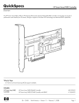
HP NC373F PCI Express Multifunction Gigabit
Server Adapter
User Guide
Part Number 417728-00B
June 2007 (Second Edition)
© Copyright 2006, 2007 Hewlett-Packard Development Company, L.P.
The information contained herein is subject to change without notice. The only warranties for HP products and services are set forth in the express
warranty statements accompanying such products and services. Nothing herein should be construed as constituting an additional warranty. HP
shall not be liable for technical or editorial errors or omissions contained herein.
Audience assumptions
This document is for the person who installs, administers, and troubleshoots servers and storage systems. HP assumes you are qualified in the
servicing of computer equipment and trained in recognizing hazards in products with hazardous energy levels.
Contents
Technician notes ........................................................................................................................... 4
Where to go for additional help.................................................................................................................. 4
HP contact information ..................................................................................................................... 5
Introduction .................................................................................................................................. 6
Overview ................................................................................................................................................. 6
LED indicators ........................................................................................................................................... 7
Installing an adapter ..................................................................................................................... 8
Installation overview .................................................................................................................................. 8
Preventing electrostatic discharge ................................................................................................................ 8
Installing an adapter in a server .................................................................................................................. 9
Installing a low profile bracket .................................................................................................................... 9
Connecting the network cable................................................................................................................... 10
Specifications ............................................................................................................................. 11
HP NC373F PCI Express Multifunction Gigabit Server Adapter specifications ................................................. 11
Regulatory compliance notices ..................................................................................................... 12
Regulatory compliance identification numbers ............................................................................................. 12
European Union regulatory notice ............................................................................................................. 12
Korean class B notice............................................................................................................................... 13
BSMI notice ............................................................................................................................................ 13
Laser compliance .................................................................................................................................... 13
Disposal of waste equipment by users in private households in the European Union ......................................... 14
Electrostatic discharge ................................................................................................................. 15
Preventing electrostatic discharge .............................................................................................................. 15
Grounding methods to prevent electrostatic discharge .................................................................................. 15
Acronyms and abbreviations........................................................................................................ 16
Index......................................................................................................................................... 17
Contents
3
Technician notes
In this section
Where to go for additional help ................................................................................................................ 4
WARNING: Only authorized technicians trained by HP should attempt to repair this
equipment. All troubleshooting and repair procedures are detailed to allow only
subassembly/module-level repair. Because of the complexity of the individual boards and
subassemblies, no one should attempt to make repairs at the component level or to make
modifications to any printed wiring board. Improper repairs can create a safety hazard.
WARNING: To reduce the risk of electric shock, personal injury, and damage to the
equipment:
• Do not attempt to service any parts of the equipment other than those specified in the
following procedure. Any other activities may require that you shut down the server and
remove the power cord.
• Installation and maintenance of this product must be performed by individuals who are
knowledgeable about the procedures, precautions and hazards associated with the
product.
WARNING: To reduce the risk of electric shock or damage to the equipment:
• Do not disable the power cord grounding plug. The grounding plug is an important safety
feature.
• Plug the power cord into a grounded (earthed) electrical outlet that is easily accessible at all
times.
• Unplug the power cord from the power supply to disconnect power to the equipment.
CAUTION: To properly ventilate the system, you must provide at least 7.6 cm (3.0 in) of
clearance at the front and back of the server.
CAUTION: The server is designed to be electrically grounded (earthed). To ensure proper
operation, plug the AC power cord into a properly grounded AC outlet only.
NOTE: Any indications of component replacement or printed wiring board modifications may
void any warranty.
Where to go for additional help
1.
Go to the HP website (http://www.hp.com).
2.
Click Software & Driver Downloads from the left menu bar.
Technician notes 4
3.
Type the product name in the For product box and press Enter. For example, type NC370T.
4.
Download the drivers, firmware, or documentation as needed.
HP contact information
For the name of the nearest HP authorized reseller:
•
In the United States, see the HP US service locator webpage (http://www.hp.com/service_locator).
•
In other locations, see the Contact HP worldwide (in English) webpage
(http://welcome.hp.com/country/us/en/wwcontact.html).
For HP technical support:
•
•
In the United States, for contact options see the Contact HP United States webpage
(http://welcome.hp.com/country/us/en/contact_us.html). To contact HP by phone:
o
Call 1-800-HP-INVENT (1-800-474-6836). This service is available 24 hours a day, 7 days a
week. For continuous quality improvement, calls may be recorded or monitored.
o
If you have purchased a Care Pack (service upgrade), call 1-800-633-3600. For more
information about Care Packs, refer to the HP website (http://www.hp.com).
In other locations, see the Contact HP worldwide (in English) webpage
(http://welcome.hp.com/country/us/en/wwcontact.html).
Technician notes 5
Introduction
In this section
Overview ................................................................................................................................................ 6
LED indicators .......................................................................................................................................... 7
Overview
The HP NC373F PCI Express Multifunction Gigabit Server Adapter is a high-performance Ethernet
adapter that delivers 1000 Mb/s Ethernet over fiber cabling. The network connection is made through an
LC fiber port. The LED indicator shows the activity and link status. See LED indicators (on page 7) for
details.
The NC373F is a supported option for selected HP ProLiant servers and offers support for both standard
and low-profile slots.
In addition to features that have shipped with other server adapters, the NC373F adapter will also
support Receive Side Scaling, TCP/IP Offload Engine (TOE), Accelerated iSCSI, and Remote Direct
Memory Access (RDMA) when those features become available. For details about each of these
advanced features and for other information regarding the latest functionality, features, and operating
system support for this server adapter, see the HP website
(http://h18004.www1.hp.com/products/servers/networking/index-nic.html).
Introduction
6
LED indicators
The NC373F adapter has a single fiber LC port and LED indicator for link activity.
LED indicator
Status
Description
LNK/ACT
Off
No link to the adapter is established. The
adapter is not receiving power or the cable
connection is faulty. No link to the adapter is
established.
On
Link to the adapter is established. The adapter
is receiving power and the cable connection is
good.
Flashing
The adapter is sending or receiving network
data at 1000 Mb/s.
Introduction
7
Installing an adapter
In this section
Installation overview ................................................................................................................................. 8
Preventing electrostatic discharge............................................................................................................... 8
Installing an adapter in a server................................................................................................................. 9
Installing a low profile bracket ................................................................................................................... 9
Connecting the network cable.................................................................................................................. 10
Installation overview
This chapter describes installation precautions, how to install the adapter, and how to connect the network
cable.
WARNING: To reduce the risk of personal injury or damage to the equipment, consult the
safety information and user documentation provided with the server before attempting the
installation.
Many servers are capable of providing energy levels that are considered hazardous and are
intended to be serviced only by qualified personnel who have been trained to deal with these
hazards. Do not remove enclosures or attempt to bypass any interlocks that may be provided
for the purpose of removing these hazardous conditions.
WARNING: Installation of this adapter should be performed by individuals who are both
qualified in the servicing of computer equipment, and trained in the hazards associated with
products capable of producing hazardous energy levels.
This adapter is intended to be installed in Certified (UL or CSA) ITE equipment having
instructions for adding and removing user installed components such as PCI, PCI-X, and PCI
Express devices. Refer to the equipment instructions to verify that it is suitable for user installed
components and that it has the power capacity to support all of the installed components.
NOTE: Before removing the cover of your server, refer to the HP documentation for the proper
methods for installing a PCI card and avoiding electric shock hazards.
Preventing electrostatic discharge
To prevent damaging the system, be aware of the precautions you need to follow when setting up the
system or handling parts. A discharge of static electricity from a finger or other conductor may damage
system boards or other static-sensitive devices. This type of damage may reduce the life expectancy of the
device.
To prevent electrostatic damage:
•
Avoid hand contact by transporting and storing products in static-safe containers.
•
Keep electrostatic-sensitive parts in their containers until they arrive at static-free workstations.
Installing an adapter 8
•
Place parts on a grounded surface before removing them from their containers.
•
Avoid touching pins, leads, or circuitry.
•
Always be properly grounded when touching a static-sensitive component or assembly.
Installing an adapter in a server
See the HP ProLiant server documentation for additional information on how to safely install a PCI Express
card in the server.
CAUTION: If the server is not PCI Hot Plug compliant, power it down and unplug the power
cord from the power outlet before removing the server access panel. Failure to do so may
damage the adapter or server.
1.
Power down the server.
2.
Remove the power cord and server access panel. Then remove the cover bracket from a PCI Express
slot.
WARNING: To reduce the risk of personal injury from hot surfaces, allow the drives and the
internal system components to cool before touching them.
3.
Firmly seat the adapter in a PCI Express slot and secure the adapter bracket.
NOTE: For 1U type servers you may need to replace the standard profile bracket with a low
profile bracket. See Installing a low profile bracket (on page 9).
4.
Replace the access panel and plug in the power cord.
Installing a low profile bracket
You may have to install a low profile bracket to complete the product installation. The low profile bracket
replaces the existing standard profile bracket shipped on the product.
To install a low profile bracket:
Installing an adapter 9
1.
Using a correctly sized slotted screwdriver, carefully remove the two board lock screws located at
the top and bottom of the connector.
2.
Remove the standard profile bracket and place the low profile bracket over the connector. Be careful
not to damage the connector or bind the low profile bracket to the connector.
Connecting the network cable
The HP NC373F PCI Express Multifunction Gigabit Server Adapter uses an LC fiber port. This port
supports multimode fiber with a maximum cable length dependent on the fiber type, mode, and cable
size. See Specifications (on page 11) for the maximum cable length.
To insert the LC connector into the adapter port, line up the slot on the fiber connector with the adapter
and gently push until the retainers click into place.
Installing an adapter
10
Specifications
In this section
HP NC373F PCI Express Multifunction Gigabit Server Adapter specifications ............................................... 11
HP NC373F PCI Express Multifunction Gigabit
Server Adapter specifications
Specification
Value
Network Controller Chipset
Broadcom 5708
Bus Type
PCI Express v1.0a
Bus Speed
2.5 GHz
Data Transfer Method
PCI Express Bus Mastering
Power Requirement
Maximum: ~2A @ 3.3V
Standards Supported
IEEE802.3x, IEEE802.3ad, IEEE802.1p, IEEE802.1Q, IEEE802.3z
Dimensions
6.5 x 2.5 in (16.5 x 6.5 cm) without bracket
Connector and Distances
Fiber LC up to 1,804 ft/550m with multimode fiber (50µm/125µm)
Interrupts Supported
Automatically configured
Temperature Range
Operating: 0°C to 55°C (32°F to 131°F)
Storage: -40 to 85°C (-40°F to 185°F)
Relative Humidity (non-condensing)
Operating: 10% to 90%
Storage: 5% to 95%
Safety Compliance
CSA Mark (US and Canada)
CE Mark
EN 60590
Specifications
11
Regulatory compliance notices
In this section
Regulatory compliance identification numbers ........................................................................................... 12
European Union regulatory notice ............................................................................................................ 12
Korean class B notice.............................................................................................................................. 13
BSMI notice ........................................................................................................................................... 13
Laser compliance ................................................................................................................................... 13
Disposal of waste equipment by users in private households in the European Union....................................... 14
Regulatory compliance identification numbers
For the purpose of regulatory compliance certifications and identification, this product has been assigned
a unique regulatory model number. The regulatory model number can be found on the product nameplate
label, along with all required approval markings and information. When requesting compliance
information for this product, always refer to this regulatory model number. The regulatory model number is
not the marketing name or model number of the product.
European Union regulatory notice
This product complies with the following EU Directives:
•
Low Voltage Directive 2006/95/EC
•
EMC Directive 2004/108/EC
•
Machinery Directive 98/37/EEC
Compliance with these directives implies conformity to applicable harmonized European standards
(European Norms) which are listed on the EU Declaration of Conformity issued by Hewlett-Packard for this
product or product family.
This compliance is indicated by the following conformity marking placed on the product:
This marking is valid for non-Telecom products and EU harmonized Telecom products (e.g. Bluetooth).
This marking is valid for EU non-harmonized Telecom products.
*Notified body number (used only if applicable—refer to the product label)
Hewlett-Packard GmbH, HQ-TRE, Herrenberger Strasse 140, 71034 Boeblingen, Germany
Regulatory compliance notices
12
Korean class B notice
BSMI notice
Laser compliance
This product may be provided with an optical storage device (that is, CD or DVD drive) and/or fiber optic
transceiver. Each of these devices contains a laser that is classified as a Class 1 Laser Product in
accordance with US FDA regulations and the IEC 60825-1. The product does not emit hazardous laser
radiation.
Each laser product complies with 21 CFR 1040.10 and 1040.11 except for deviations pursuant to Laser
Notice No. 50, dated May 27, 2001; and with IEC 60825-1:1993/A2:2001.
WARNING: Use of controls or adjustments or performance of procedures other than those
specified herein or in the laser product's installation guide may result in hazardous radiation
exposure. To reduce the risk of exposure to hazardous radiation:
• Do not try to open the module enclosure. There are no user-serviceable components inside.
• Do not operate controls, make adjustments, or perform procedures to the laser device other
than those specified herein.
• Allow only HP Authorized Service technicians to repair the unit.
The Center for Devices and Radiological Health (CDRH) of the U.S. Food and Drug Administration
implemented regulations for laser products on August 2, 1976. These regulations apply to laser products
manufactured from August 1, 1976. Compliance is mandatory for products marketed in the United States.
Regulatory compliance notices
13
Disposal of waste equipment by users in private
households in the European Union
This symbol on the product or on its packaging indicates that this product must not be disposed of with
your other household waste. Instead, it is your responsibility to dispose of your waste equipment by
handing it over to a designated collection point for the recycling of waste electrical and electronic
equipment. The separate collection and recycling of your waste equipment at the time of disposal will
help to conserve natural resources and ensure that it is recycled in a manner that protects human health
and the environment. For more information about where you can drop off your waste equipment for
recycling, please contact your local city office, your household waste disposal service or the shop
where you purchased the product.
Regulatory compliance notices
14
Electrostatic discharge
In this section
Preventing electrostatic discharge............................................................................................................. 15
Grounding methods to prevent electrostatic discharge ................................................................................ 15
Preventing electrostatic discharge
To prevent damaging the system, be aware of the precautions you need to follow when setting up the
system or handling parts. A discharge of static electricity from a finger or other conductor may damage
system boards or other static-sensitive devices. This type of damage may reduce the life expectancy of the
device.
To prevent electrostatic damage:
•
Avoid hand contact by transporting and storing products in static-safe containers.
•
Keep electrostatic-sensitive parts in their containers until they arrive at static-free workstations.
•
Place parts on a grounded surface before removing them from their containers.
•
Avoid touching pins, leads, or circuitry.
•
Always be properly grounded when touching a static-sensitive component or assembly.
Grounding methods to prevent electrostatic
discharge
Several methods are used for grounding. Use one or more of the following methods when handling or
installing electrostatic-sensitive parts:
•
Use a wrist strap connected by a ground cord to a grounded workstation or computer chassis. Wrist
straps are flexible straps with a minimum of 1 megohm ±10 percent resistance in the ground cords.
To provide proper ground, wear the strap snug against the skin.
•
Use heel straps, toe straps, or boot straps at standing workstations. Wear the straps on both feet
when standing on conductive floors or dissipating floor mats.
•
Use conductive field service tools.
•
Use a portable field service kit with a folding static-dissipating work mat.
If you do not have any of the suggested equipment for proper grounding, have an authorized reseller
install the part.
For more information on static electricity or assistance with product installation, contact an authorized
reseller.
Electrostatic discharge 15
Acronyms and abbreviations
ACPI
Advanced Configuration and Power Interface
APM
advanced power management
CSA
Canadian Standards Association
DMA
direct memory access
IEEE
Institute of Electrical and Electronics Engineers
iSCSI
Internet Small Computer System Interface
MDI-X
medium dependent interface-crossover
PCI Express
Peripheral Component Interconnect Express
RDMA
Remote Direct Memory Access
RSS
Receive-Side Scaling
TOE
TCP/IP Offload Engine
UTP
unshielded twisted pair
Acronyms and abbreviations
16
Index
B
bracket, low profile 9
C
cables, networking 10
cautions 4
E
electrostatic discharge 8, 15
F
features 6
G
grounding methods 15
I
installation overview 8
installing adapters 9
N
NIC LEDs 7
R
regulatory compliance notices 12
S
specifications 11
Index 17