1
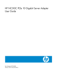
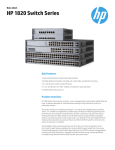
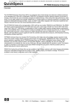
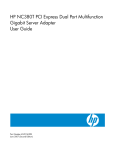
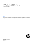
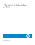
HP NC522SFP Dual Port 10 GbE Server
Adapter
User Guide
Part Number 537709-001
March 2009 (First Edition)
© Copyright 2009 Hewlett-Packard Development Company, L.P.
The information contained herein is subject to change without notice. The only warranties for HP products and services are set forth in the express
warranty statements accompanying such products and services. Nothing herein should be construed as constituting an additional warranty. HP
shall not be liable for technical or editorial errors or omissions contained herein.
Intended audience
This document is for the person who installs, administers, and troubleshoots servers and storage systems.
HP assumes you are qualified in the servicing of computer equipment and trained in recognizing hazards
in products with hazardous energy levels.
Contents
Technician notes ........................................................................................................................... 4
Warnings, cautions, and notes.................................................................................................................... 4
Downloading files ..................................................................................................................................... 5
HP contact information ............................................................................................................................... 5
Introduction .................................................................................................................................. 6
Overview ................................................................................................................................................. 6
LED indicators ........................................................................................................................................... 6
Installing an adapter ..................................................................................................................... 9
Installation overview .................................................................................................................................. 9
Preventing electrostatic discharge ................................................................................................................ 9
Installing an adapter in a server ................................................................................................................ 10
Installing a low profile bracket .................................................................................................................. 10
Connecting the network cable................................................................................................................... 11
Specifications ............................................................................................................................. 12
Cable specifications ................................................................................................................................ 12
General specifications ............................................................................................................................. 12
Compliance............................................................................................................................................ 12
Power and environmental specifications ..................................................................................................... 13
Regulatory compliance notices ..................................................................................................... 14
Regulatory compliance identification numbers ............................................................................................. 14
Federal Communications Commission notice............................................................................................... 14
European Union regulatory notice ............................................................................................................. 14
Canadian notice ..................................................................................................................................... 15
Korean class A notice .............................................................................................................................. 15
Japanese class A notice ........................................................................................................................... 15
Disposal of waste equipment by users in private households in the European Union ......................................... 15
Electrostatic discharge ................................................................................................................. 16
Preventing electrostatic discharge .............................................................................................................. 16
Grounding methods to prevent electrostatic discharge .................................................................................. 16
Acronyms and abbreviations........................................................................................................ 17
Index......................................................................................................................................... 18
Contents
3
Technician notes
Warnings, cautions, and notes
WARNING: Only authorized technicians trained by HP should attempt to repair this
equipment. All troubleshooting and repair procedures are detailed to allow only
subassembly/module-level repair. Because of the complexity of the individual boards and
subassemblies, no one should attempt to make repairs at the component level or to make
modifications to any printed wiring board. Improper repairs can create a safety hazard.
WARNING: To reduce the risk of electric shock, personal injury, and damage to the
equipment:
• Do not attempt to service any parts of the equipment other than those specified in the
following procedure. Any other activities may require that you shut down the server and
remove the power cord.
• Installation and maintenance of this product must be performed by individuals who are
knowledgeable about the procedures, precautions and hazards associated with the
product.
WARNING: To reduce the risk of electric shock or damage to the equipment:
• Do not disable the power cord grounding plug. The grounding plug is an important safety
feature.
• Plug the power cord into a grounded (earthed) electrical outlet that is easily accessible at all
times.
• Unplug the power cord from the power supply to disconnect power to the equipment.
• Do not route the power cord where it can be walked on or pinched by items placed against
it. Pay particular attention to the plug, electrical outlet, and the point where the cord
extends from the server.
This symbol indicates the presence of a hot surface or hot component. If this surface is
contacted, the potential for injury exists.
WARNING: To reduce the risk of injury from a hot component, allow the surface to
cool before touching.
CAUTION: To properly ventilate the system, you must provide at least 7.6 cm (3.0 in) of
clearance at the front and back of the server.
CAUTION: The server is designed to be electrically grounded (earthed). To ensure proper
operation, plug the AC power cord into a properly grounded AC outlet only.
Technician notes 4
NOTE: Any indications of component replacement or printed wiring board modifications may
void any warranty.
Downloading files
1.
Go to the HP website (http://www.hp.com/#Support).
2.
Select Download drivers and software (and firmware).
3.
Type the adapter name in the For product box and then click Go. For example, type NC522SFP.
4.
Download the drivers, firmware, or documentation as needed.
HP contact information
For the name of the nearest HP authorized reseller:
•
See the Contact HP worldwide (in English) webpage
(http://welcome.hp.com/country/us/en/wwcontact.html).
For HP technical support:
•
•
In the United States, for contact options see the Contact HP United States webpage
(http://welcome.hp.com/country/us/en/contact_us.html). To contact HP by phone:
o
Call 1-800-HP-INVENT (1-800-474-6836). This service is available 24 hours a day, 7 days a
week. For continuous quality improvement, calls may be recorded or monitored.
o
If you have purchased a Care Pack (service upgrade), call 1-800-633-3600. For more
information about Care Packs, refer to the HP website (http://www.hp.com/hps).
In other locations, see the Contact HP worldwide (in English) webpage
(http://welcome.hp.com/country/us/en/wwcontact.html).
Technician notes 5
Introduction
Overview
The HP NC522SFP Dual Port 10 GbE Server Adapter is a dual port PCI Express (PCIe) 10 Gigabit
ProLiant Ethernet adapter. The network connection is made through two 10GBASE-SFP+ modules.
In addition to standard HP network server adapter features, the NC522SFP is capable of supporting
teaming for load balancing and failover, TCP checksum and segmentation (LSO) offload capability, VLAN
tagging, jumbo frames, IPv6, and other features. The NC522SFP can be installed in either standard or
low profile slots.
LED indicators
The NC522SFP adapter has two ports with LED indicators for Link and Act. (activity) for each port.
Standard-height and low-profile brackets are shown below with the fiber LC port and LED indicators.
The NC522SFP 10 Gigabit Server Adapter LED indicators operate as described in the following table.
LED indicator
Status
Description
Act.
Off
Indicates no network activity on the link.
Flashing
(Green)
Indicates network activity on the link. The
adapter is sending or receiving network
data at up to 10Gbps.
Off
No link to the adapter is established. The
adapter is not receiving power or the
cable connection is faulty.
Link
Introduction
6
LED indicator
Status
Description
On (Green)
Link to the adapter is established. The
adapter is receiving power and the cable
connection is good.
HP Direct Attach copper cables, fiber optic cable, and SFP+ module part numbers are listed in the
following tables.
Direct attach
copper cable
(0.5 - 10 m)
Part number
HP 0.5 m SFP+
10 GbE Copper
Cable
487649-B21
HP 1 m SFP+
10 GbE Copper
Cable
487652-B21
HP 3 m SFP+
10 GbE Copper
Cable
487655-B21
HP 7 m SFP+
10 GbE Copper
Cable
487658-B21
Fiber Optic Cable Part number
(0.5 to 50 m)
HP 2 m LC-LC
Multi-Mode OM2
Fiber Optic Cable
221692-B21
HP 5 m LC-LC
Multi-Mode OM2
Fiber Optic Cable
221692-B22
HP 15 m LC-LC
Multi-Mode OM2
Fiber Optic Cable
221692-B23
HP 30 m LC-LC
Multi-Mode OM2
Fiber Optic Cable
221692-B26
HP 50 m LC-LC
Multi-Mode OM2
Fiber Optic Cable
221692-B27
HP .5 m LC-LC
Multi-Mode OM3
Fiber Optic Cable
AJ833A
HP 1 m LC-LC
Multi-Mode OM3
Fiber Optic Cable
AJ834A
Introduction
7
HP 2 m LC-LC
Multi-Mode OM3
Fiber Optic Cable
AJ835A
HP 5 m LC-LC
Multi-Mode OM3
Fiber Optic Cable
AJ836A
HP 15 m LC-LC
Multi-Mode OM3
Fiber Optic Cable
AJ837A
HP 30 m LC-LC
Multi-Mode OM3
Fiber Optic Cable
AJ838A
HP 50 m LC-LC
Multi-Mode OM3
Fiber Optic Cable
AJ839A
SFP+ module
Part number
HP BladeSystem
10Gb SR SFP+
455883-B21
HP BladeSystem
10Gb LR SFP+
455886-B21
HP BladeSystem
10Gb LRM SFP+
455889-B21
Introduction
8
Installing an adapter
Installation overview
This section describes installation precautions, how to install the adapter, and how to connect the network
cable.
WARNING: To reduce the risk of personal injury or damage to the equipment, consult the
safety information and user documentation provided with the server before attempting the
installation.
Many servers are capable of providing energy levels that are considered hazardous and are
intended to be serviced only by qualified personnel who have been trained to deal with these
hazards. Do not remove enclosures or attempt to bypass any interlocks that may be provided
for the purpose of removing these hazardous conditions.
WARNING: Installation of this adapter should be performed by individuals who are both
qualified in the servicing of computer equipment, and trained in the hazards associated with
products capable of producing hazardous energy levels.
This adapter is intended to be installed in Certified (UL or CSA) ITE equipment having
instructions for adding and removing user installed components such as PCI, PCI-X, and PCI
Express devices. Refer to the equipment instructions to verify that it is suitable for user installed
components and that it has the power capacity to support all of the installed components.
NOTE: Before removing the cover of your server, refer to the HP documentation for the proper
methods for installing a PCI Express card and avoiding electric shock hazards.
Preventing electrostatic discharge
To prevent damaging the system, be aware of the precautions you need to follow when setting up the
system or handling parts. A discharge of static electricity from a finger or other conductor may damage
system boards or other static-sensitive devices. This type of damage may reduce the life expectancy of the
device.
To prevent electrostatic damage:
•
Avoid hand contact by transporting and storing products in static-safe containers.
•
Keep electrostatic-sensitive parts in their containers until they arrive at static-free workstations.
•
Place parts on a grounded surface before removing them from their containers.
•
Avoid touching pins, leads, or circuitry.
•
Always be properly grounded when touching a static-sensitive component or assembly.
Installing an adapter 9
Installing an adapter in a server
See the HP ProLiant server documentation for additional information on how to safely install a PCI Express
card in the server.
CAUTION: If the server is not PCI Hot Plug compliant, power it down and unplug the power
cord from the power outlet before removing the server access panel. Failure to do so may
damage the adapter or server.
1.
Power down the server.
2.
Remove the power cord and server access panel. Then remove the cover bracket from a PCI Express
slot.
WARNING: To reduce the risk of personal injury from a hot component, allow the surface of
the option card to cool before touching it.
WARNING: To reduce the risk of personal injury from hot surfaces, allow the drives and the
internal system components to cool before touching them.
3.
Firmly seat the adapter in a PCI Express slot and secure the adapter bracket.
NOTE: For 1U type servers you may need to replace the standard profile bracket with a low
profile bracket. See Installing a low profile bracket.
4.
Replace the access panel and plug in the power cord.
Installing a low profile bracket
You may have to install a low profile bracket to complete the product installation. The low profile bracket
replaces the existing standard profile bracket shipped on the product.
1.
Remove the SFP modules by pulling down on the bail latch handle located near the connector, and
then pulling the SFP modules out.
Installing an adapter
10
2.
Using a correctly sized Phillips head screwdriver, carefully remove the two board lock screws
located at the top and bottom of the connector.
3.
Remove the standard profile bracket and place the low profile bracket over the connector. Be careful
not to damage the connector or bend the low profile bracket.
4.
Reinstall the two Phillips screws.
5.
Orient the SFP modules with the label side down and then reinstall the modules all the way into their
sockets until they click into place and latch securely.
Connecting the network cable
The HP NC522SFP Dual Port 10 GbE Server Adapter uses two SFP+ ports. These ports support either
direct attached cable or optical modules. See Cable specifications (on page 12) for the maximum cable
length.
Installing an adapter
11
Specifications
Cable specifications
SFP+ modules or
copper cable
Fiber type
Cable grade
Minimum modal
Operating range
bandwidth @ 850 (meters)
nm (MHz-km)
10GBASE-SR
(short range)
62.5 µm MMF
FDDI
160
2 to 26
62.5 µm MMF
OM1
200
2 to 33
50 µm MMF
OM2
500
2 to 82
50 µm MMF
OM3
2000
2 to 300
10GBASE-LRM
(long reach
multimode)
50, 62.5 µm MMF
OM1, OM2, OM3
N/A
0.5 to 220
10GBASE-LR
10 µm SMF
B1.1, B1.3 SMF
N/A
2 to 10,000
Twin Axial Copper
@26 AWG
N/A
.5 - 10
(long range)
Direct attached
copper
General specifications
General
specifications
Value
Controller
NETXEN NX3031
Data rate
10Gbps, full-duplex
PCI bus
8 Lane (x8) PCI Express Gen 2, compatible with x4 and x8 bus widths
Connectors
2 SFP+
Dimensions (LxW)
6.6 x 2.7 inches (16.734 cm x 6.85 cm) without bracket
Compliance
Compliance
Standard
IEEE
IEEE802.3x, IEEE802.3ad, IEEE802.1p, IEEE802.1q, IEEE802.3z, IEEE802.3ae
Safety
UL Mark (US and Canada)
EN 60950
Specifications
12
Compliance
Standard
Other
PCIe v2.0
RoHS 6 of 6
IPv4, IPv6
CE
ACPI 1.1a
Microsoft WHQL (Windows Hardware Quality Labs)
Server Design Guide version 3.0 (SDG 3.0)
Power and environmental specifications
Power and
environmental
specifications
Value
Operating
Temperature
Non-operating
Power
32° to 131° F (0° to 55° C )
Humidity
10% to 90%
Temperature
-85° to 185° F (-65° to 85° C)
Humidity
5% to 95%
2.03A @ 12 V and 570 mA @ 3.3 V maximum
Specifications
13
Regulatory compliance notices
Regulatory compliance identification numbers
For the purpose of regulatory compliance certifications and identification, this product has been assigned
a unique regulatory model number. The regulatory model number can be found on the product nameplate
label, along with all required approval markings and information. When requesting compliance
information for this product, always refer to this regulatory model number. The regulatory model number is
not the marketing name or model number of the product.
Federal Communications Commission notice
This equipment has been tested and found to comply with the limits for a Class A digital device, pursuant
to Part 15 of the FCC Rules. These limits are designed to provide reasonable protection against harmful
interference when the equipment is operated in a commercial environment. This equipment generates,
uses, and can radiate radio frequency energy and, if not installed and used in accordance with the
instructions, may cause harmful interference to radio communications. Operation of this equipment in a
residential area is likely to cause harmful interference, in which case the user will be required to correct
the interference at personal expense.
European Union regulatory notice
This product complies with the following EU Directives:
•
Low Voltage Directive 2006/95/EC
•
EMC Directive 2004/108/EC
Compliance with these directives implies conformity to applicable harmonized European standards
(European Norms) which are listed on the EU Declaration of Conformity issued by Hewlett-Packard for this
product or product family.
This compliance is indicated by the following conformity marking placed on the product:
This marking is valid for non-Telecom products and EU harmonized Telecom products (e.g. Bluetooth).
This marking is valid for EU non-harmonized Telecom products.
*Notified body number (used only if applicable—refer to the product label)
Hewlett-Packard GmbH, HQ-TRE, Herrenberger Strasse 140, 71034 Boeblingen, Germany
Regulatory compliance notices
14
Canadian notice
This Class A digital apparatus meets all requirements of the Canadian Interference-Causing Equipment
Regulations.
Cet appareil numérique de la classe A respecte toutes les exigences du Règlement sur le matériel
brouilleur du Canada.
Korean class A notice
Japanese class A notice
Disposal of waste equipment by users in private
households in the European Union
This symbol on the product or on its packaging indicates that this product must not be disposed
of with your other household waste. Instead, it is your responsibility to dispose of your waste
equipment by handing it over to a designated collection point for the recycling of waste
electrical and electronic equipment. The separate collection and recycling of your waste
equipment at the time of disposal will help to conserve natural resources and ensure that it is
recycled in a manner that protects human health and the environment. For more information
about where you can drop off your waste equipment for recycling, please contact your local
city office, your household waste disposal service or the shop where you purchased the
product.
Regulatory compliance notices
15
Electrostatic discharge
Preventing electrostatic discharge
To prevent damaging the system, be aware of the precautions you need to follow when setting up the
system or handling parts. A discharge of static electricity from a finger or other conductor may damage
system boards or other static-sensitive devices. This type of damage may reduce the life expectancy of the
device.
To prevent electrostatic damage:
•
Avoid hand contact by transporting and storing products in static-safe containers.
•
Keep electrostatic-sensitive parts in their containers until they arrive at static-free workstations.
•
Place parts on a grounded surface before removing them from their containers.
•
Avoid touching pins, leads, or circuitry.
•
Always be properly grounded when touching a static-sensitive component or assembly.
Grounding methods to prevent electrostatic
discharge
Several methods are used for grounding. Use one or more of the following methods when handling or
installing electrostatic-sensitive parts:
•
Use a wrist strap connected by a ground cord to a grounded workstation or computer chassis. Wrist
straps are flexible straps with a minimum of 1 megohm ±10 percent resistance in the ground cords.
To provide proper ground, wear the strap snug against the skin.
•
Use heel straps, toe straps, or boot straps at standing workstations. Wear the straps on both feet
when standing on conductive floors or dissipating floor mats.
•
Use conductive field service tools.
•
Use a portable field service kit with a folding static-dissipating work mat.
If you do not have any of the suggested equipment for proper grounding, have an authorized reseller
install the part.
For more information on static electricity or assistance with product installation, contact an authorized
reseller.
Electrostatic discharge 16
Acronyms and abbreviations
CSA
Canadian Standards Association
DMA
direct memory access
IEEE
Institute of Electrical and Electronics Engineers
iSCSI
Internet Small Computer System Interface
PCI Express
Peripheral Component Interconnect Express
RDMA
Remote Direct Memory Access
RSS
Receive-Side Scaling
SFP
small form-factor pluggable
TOE
TCP/IP Offload Engine
Acronyms and abbreviations
17
Index
A
S
adapter LEDs 6
adapters 6
specifications 12, 13
standards 14
B
T
bracket, low profile 10
technical notes 4
C
V
cables, networking 11
compliance 12, 14
contact information 5
ventilation 4
D
warnings 4
W
disposal, waste 15
downloading files 5
E
electrostatic discharge 9, 16
environmental specifications 13
F
features 6
G
grounding methods 16
L
LC connector 11
LEDs 6
low profile bracket 10
P
PCI (peripheral component interface) 9
power specifications 13
R
regulatory compliance notices 14, 15
Index 18