1
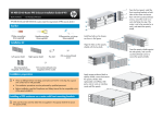
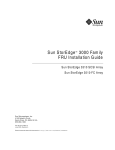
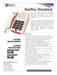
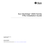
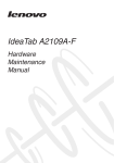
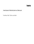
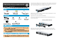
Face the front panel, install the front mounting brackets on both sides of the router and secure
them with M4 countersunk-head screws, mount the router on a rack shelf (skip this step if the
router is not to be mounted on a rack), and attach the opacity shield.
Install hex bolts on the chassis as shown in the figures. (Remove the fastening screws, if any,
from where hex bolts 2 are to be installed.)
Align the holes on the opacity shields with the hex bolts.
Press the opacity shields against the side panels, and use M3 countersunk-head screws to
secure the opacity shields.
Hex bolts 1 (Male M4, Female M3)
Hex bolts 2 (Male M3, Female M3)
1
2
Apply tamper-evidence labels to opacity shields, screws that secure the opacity shields,
field replaceable units (FRUs), USB ports, and air vents on interface cards and filler panels.
Installing a FIPS enclosure on a router with rear mounting brackets
Only use the screws and hex bolts that are supplied in the opacity shield kit to secure
the opacity shield.
Face the rear panel, install the rear mounting brackets on both sides of the router and
secure them with M4 countersunk-head screws, mount the router on a rack shelf (skip this
step if the router is not to be mounted on a rack), and attach the opacity shield.
Install hex bolts on the chassis as shown in the figures. (Remove the fastening screws, if any,
from where hex bolts 2 are to be installed.)
Align the holes on the opacity shields with the hex bolts.
Press the opacity shields against the side panels, and use M3 countersunk-head screws to
secure the opacity shields.
Hex bolts 1 (Male M4, Female M3)
Hex bolts 2 (Male M3, Female M3)
1
2
Apply tamper-evidence labels to opacity shields, screws that secure the opacity shields, field
replaceable units (FRUs), USB ports, and air vents on interface cards and filler panels.
© Copyright 2012 Hewlett-Packard Development Company, L.P.
The information contained herein is subject to change without notice.
5998-3552