1
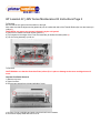
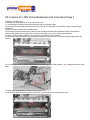
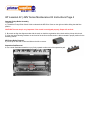
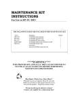
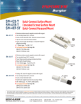
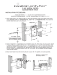
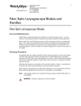
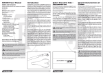
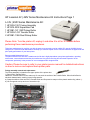
800-551-1943
HP LaserJet 4V | 4MV Series Maintenance Kit Instructions Page 1
LJ 4V | 4MV Series Maintenance Kit:
1 HP RG5-1557 Fusing Assembly
1 HP RF5-0302 Separation Pad
1 HP RB1-1411 MP Pickup Roller
1 HP RG5-1410 Transfer Roller
2 HP RB1-1386 Dual Pickup Roller
Please Note: Turn the printer off, unplug it, and allow it to sit for 30 minutes before
performing these maintenance procedures.
This printer maintenance kit provides you with the parts most commonly used to rebuild HP LaserJet 4V/4MV printers.
Using the HP LaserJet Printer Maintenance Kit helps you eliminate repeat service calls and maximize the paper feed and
print quality performance of your laser printer.
Recommended Maintenance Level:
The parts included in this kit have a variable service life that is highly dependent upon printer applications, operating
environment, user maintenance and the print media used. Any printer servicing should include inspection of the
components, particularly in the presence of error messages and/or image defects.
Caution: Please be sure to refer to your printer service manual for detailed instructions
on how to remove and replace these printer parts.
Fusing assembly removal and replacement
The Fusing assembly is located on the upper portion of the printer door.
1). Remove the Transfer Roller
Handle the Transfer Roller from the ends only. Do not touch the surface of the Transfer Roller. Skin oils will affect its
electrical characteristics, resulting in poor image transfer.
a). Grasp the shaft on either end of the Transfer Roller and lift upward to snap out of the plastic retainer clip (callout 1).
b). Lift the opposite end up and out of its retainer clip.
800-551-1943
HP LaserJet 4V | 4MV Series Maintenance Kit Instructions Page 2
To Reinstall:
Be sure that the non-gear end of the shaft is to the right.
Also make sure that the alignment slot (plastic tab) on the underneath side of the Transfer Roller slips over the locator pin
(callout 2).
CAUTION Do not remove two screws indicated in by the null symbol
2). Remove five machine shoulder screws (callout 3).
a). Pull outward on the edges of the Front Door assembly to release the shaft (callout 4).
b). Lift the Fusing assembly up and out.
To Reinstall:
CAUTION Make sure that the Protection Plate (callout 5) is in place or damage to the toner cartridge drum will
occur.
Cassette Pick Roller Removal
1) Remove top cover
a. Open front door
b. Remove two screws from right and left side of cover
c. Lift front of cover up slightly and push to the back until cover releases
d. Disconnect display cable and remove cover
800-551-1943
HP LaserJet 4V | 4MV Series Maintenance Kit Instructions Page 3
2) Remove right side cover
a. Release one tab towards top of cover and remove cover.
1). The Cassette Pickup Roller assembly is located under the Cartridge Guide.
The removal of this assembly requires prior removal of the top and right side covers and will require a stubby Phillips
screwdriver.
a). Remove Paper Cassette and Cartridge Guide.
The Cartridge Guide is located directly under the toner cartridge and behind the Registration Rollers. Note that the
removal of this guide does not require prior removal of the Upper Cover or any upper area assemblies.
a); Using a stubby Phillips screwdriver, remove the two self-tapping screws (callout 6).
b); Lift the front edge of the plate upward and slide it forward, out of the printer. Note that the plate fits tightly within the
opening.
6papgdew mf
b). From the right side of the printer, remove the pickup clutch alignment guide (callouts 7 & 8). Unplug and free the clutch
cable.
c). Remove two small diameter, machine screws (callout 10).
d). Tilt the roller shaft upward from the left end and lift out, being careful not to damage the cable.
800-551-1943
HP LaserJet 4V | 4MV Series Maintenance Kit Instructions Page 4
Cassette Pickup Roller Assembly
To Reinstall:
e). Thread the Pickup Roller Clutch Cable underneath the MP Drive Gears on the right end while sliding the shaft into
position.
CAUTION The next step is very important. If the clutch is not aligned properly, Paper will not feed.
f). Be certain to align the alignment tabs with the notch on both the registration roller clutch and the pickup roller clutch.
g). Align the plastic bearing retainers on each end of the shaft so the flat portion is facing upward in proper position for the
mounting screws.
MP Pickup Roller Removal
a). Pinch clip on left side of roller and slide to the left to remove.
Separation Pad Removal
b. Use a small flat blade screwdriver to pry firmly upward at either end of the separation pad.