1
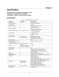
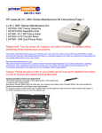
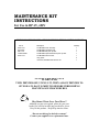
MAINTENANCE KIT
INSTRUCTIONS
For Use in HP 4V, 4MV
THE FOLLOWING PARTS ARE INCLUDED IN THIS MAINTENANCE KIT
Part #
RG5-1557
RF5-0302
RB1-1411
C3960-60506
RG5-1410
Description
4V,4MV/BXII fuser assembly
4V,4MV/BXII separation pad
4V,4MV/BXII MP pick up roller
4V,4MV/BXII Optional 500 sheet pick up roller
4V,4MV/BXII transfer roller
vinyl gloves
manual 4V,4MV/BXII maintenance kit
Quantity
1
1
1
1
1
2
1
****WARNING****
TURN PRINTER OFF, UNPLUG IT, THEN ALLOW PRINTER TO
SIT FOR AT LEAST 30 MINUTES BEFORE PERFORMING
MAINTENANCE PROCEEDURES
Buy Smart. Waste Less. Save More!!
Although you are not required, please do your part.
Inside you will find an ARS tag provided for you to
Recycle this product – Help keep America clean.
“Do not use this tag for defective returns”
Contact your supplier for a replacement fuser
****WARNING****
TURN PRINTER OFF, UNPLUG IT, THEN ALLOW PRINTER TO SIT FOR AT LEAST
30 MINUTES BEFORE PERFORMING MAINTENANCE PROCEEDURES
Fuser Removal & Installation:
1.
2.
3.
4.
Remove the paper tray and toner cartridge from the printer.
Open the rear door – remove top and right side covers.
Remove the five shoulder screws securing the fuser to the inside of the door.
Release the fuser from the door by unlatching the rod at each side with a flathead screwdriver and
pull the fuser evenly away from the door.
Separation Pad Replacement:
1.
2.
Using a flathead screwdriver “gently” pry up on the separation pad at either side until it snaps out
of place.
Insert the new separation pad – make sure the springs are in proper alignment - push until it snaps
into place.
Main Pick Up Roller Removal & Replacement:
1.
2.
Locate main pickup roller on the underside of the printer. Pinch the clip on the pick up roller and
slide it to the left removing it from shaft.
Slide the new main pickup roller onto the shaft until it snaps into place.
(note: it may be necessary to turn the roller while doing this)
***WARNING***
USE LATEX GLOVES WHEN REPLACING THE
TRANSFER ROLLER – DO NOT TOUCH THE FOAM SURFACE
Transfer Roller Replacement:
3.
4.
5.
6.
While wearing latex gloves, open the top cover and locate the transfer roller.
Using a flathead screwdriver “gently” pry up on the transfer roller shaft until it snaps out of place.
Lift and remove the transfer roller.
Insert the right side of the new transfer roller, press down on the left side until it snaps into place.
Lower Pick Up Roller Removal
& Replacement:
NOTE THE POSITION OF THE CLUTCH ALIGNMENT GUIDE ON
THE RIGHT END OF THE PICK UP ROLLER SHAFT, IT MUST BE
PROPERLY POSITIONED WHEN REASSEMBLED
1.
2.
3.
4.
5.
6.
7.
Remove the alignment guide and unplug the clutch connector.
Remove two screws from the cartridge guide and lift it out.
Remove the two screws securing the pick up assembly bushings, lift the left end of the assembly
and guide it out to the left.
Remove the e-rings at the left side of each pick up roller and slide them off the shaft, replace with
new rollers. (note- it may be necessary to turn the rollers while doing this)
Replace the roller assembly in the printer.
– take care to route the clutch wires under the drive gears.
Complete by reverse of removal – take care to properly position with the alignment slot.