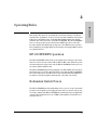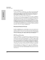
1
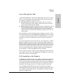
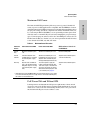
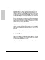
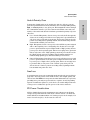
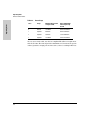
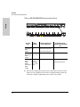
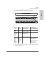
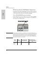
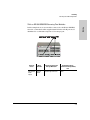
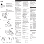
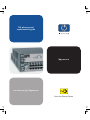
PoE planning and implementation guide hp procurve www.hp.com/go/hpprocurve PoE Power over Ethernet Devices HP ProCurve PoE Planning and Implementation Guide © Copyright 2003 Hewlett-Packard Development Company, L.P. The information contained herein is subject to change without notice. This document contains proprietary information, which is protected by copyright. No part of this document may be photocopied, reproduced, or translation into another language without the prior written consent of Hewlett-Packard. Publication Number HEWLETT-PACKARD COMPANY MAKES NO WARRANTY OF ANY KIND WITH REGARD TO THIS MATERIAL, INCLUDING, BUT NOT LIMITED TO, THE IMPLIED WARRANTIES OF MERCHANTABILITY AND FITNESS FOR A PARTICULAR PURPOSE. Hewlett-Packard shall not be liable for errors contained herein or for incidental or consequential damages in connection with the furnishing, performance, or use of this material. The only warranties for HP products and services are set forth in the express warranty statements accompanying such products and services. Nothing herein should be construed as constituting an additional warranty. HP shall not be liable for technical or editorial errors or omissions contained herein. 5990-6045 November 2003 Edition 1 Applicable Products HP ProCurve Switch 2626-PWR HP ProCurve Switch 2650-PWR HP ProCurve Switch xl PoE Module HP ProCurve 600 Redundant and External Power Supply Disclaimer Hewlett-Packard assumes no responsibility for the use or reliability of its software on equipment that is not furnished by Hewlett-Packard. (J8164A) (J8165A) (J8161A) (J8168A) Trademark Credits Windows NT®, Windows®, and MS Windows® are US registered trademarks of Microsoft Corporation. Warranty See the Customer Support/Warranty booklet included with the product. A copy of the specific warranty terms applicable to your HewlettPackard products and replacement parts can be obtained from your HP Sales and Service Office or authorized dealer. Contents 1 Introduction Overview . . . . . . . . . . . . . . . . . . . . . . . . . . . . . . . . . . . . . . . . . . . . . . . . . . . . . . 1-1 Power Through the Cable . . . . . . . . . . . . . . . . . . . . . . . . . . . . . . . . . . . 1-3 PoE Capabilities of the Products . . . . . . . . . . . . . . . . . . . . . . . . . . . . . . 1-3 2 Operating Rules HP 600 RPS/EPS Operation . . . . . . . . . . . . . . . . . . . . . . . . . . . . . . . . . . . . . . . 2-1 Redundant Switch Power . . . . . . . . . . . . . . . . . . . . . . . . . . . . . . . . . . . . . . . . 2-1 External Switch Power . . . . . . . . . . . . . . . . . . . . . . . . . . . . . . . . . . . . . . . . . . 2-2 EPS Power Allocation . . . . . . . . . . . . . . . . . . . . . . . . . . . . . . . . . . . . . . . 2-2 Maximum PoE Power . . . . . . . . . . . . . . . . . . . . . . . . . . . . . . . . . . . . . . . 2-3 PoE Power With and Without EPS . . . . . . . . . . . . . . . . . . . . . . . . . . . . . 2-3 Switch Port Priority . . . . . . . . . . . . . . . . . . . . . . . . . . . . . . . . . . . . . . . . . 2-4 Switch Priority Class . . . . . . . . . . . . . . . . . . . . . . . . . . . . . . . . . . . . . . . . . 2-5 Line Loss . . . . . . . . . . . . . . . . . . . . . . . . . . . . . . . . . . . . . . . . . . . . . . . . . . 2-5 PD Power Classification . . . . . . . . . . . . . . . . . . . . . . . . . . . . . . . . . . . . . 2-5 3 Planning PD Power Requirements . . . . . . . . . . . . . . . . . . . . . . . . . . . . . . . . . . . . . . . . . 3-1 Supported Products . . . . . . . . . . . . . . . . . . . . . . . . . . . . . . . . . . . . . . . . . . . . . 3-2 Number of PDs per Switch . . . . . . . . . . . . . . . . . . . . . . . . . . . . . . . . . . . . . . . 3-2 Planning Your PoE Configuration . . . . . . . . . . . . . . . . . . . . . . . . . . . . . . . . . 3-2 HP ProCurve 2626-PWR Configurations . . . . . . . . . . . . . . . . . . . . . . . . 3-3 With an HP 600 RPS/EPS Powering One Switch . . . . . . . . . . . . . . 3-3 With an HP 600 RPS/EPS Powering Two Switches . . . . . . . . . . . . 3-4 HP ProCurve 2650-PWR Configurations . . . . . . . . . . . . . . . . . . . . . . . . 3-5 With an HP 600 RPS/EPS Powering One Switch . . . . . . . . . . . . . . 3-6 With an HP 600 RPS/EPS Powering Two Switches . . . . . . . . . . . . 3-7 i HP ProCurve Switch xl PoE Module Configurations . . . . . . . . . . . . . . 3-8 With an HP 600 RPS/EPS Powering One Module . . . . . . . . . . . . . . 3-8 With an HP 600 RPS/EPS Powering Two Modules . . . . . . . . . . . . 3-9 Infrastructure Requirements . . . . . . . . . . . . . . . . . . . . . . . . . . . . . . . . . . . . . 3-10 Glossary Index ii 1 Introduction Overview Power over Ethernet technology allows IP telephones, wireless LAN Access Points and other appliances to receive power as well as data over existing LAN cabling, without needing to modify the existing Ethernet infrastructure. IEEE 802.3af is an extension to the existing Ethernet standards. Power Over Ethernet is likely to become a standard feature of ethernet switches in a few years, as the cost of adding power supplies to the Ethernet switches is going to be small. It offers the first truly international standard for power distribu tion (consider how many different AC power plugs exist worldwide). Almost all appliances require both data connectivity and a power supply. Just as telephones are powered from the telephone exchange through the same twisted pair that carries the voice, we can now do the same thing with Ethernet devices. The technology is bound to make a big impact in the world of embedded computing. In the realm of embedded computers, where the systems are increasingly connected to LANs and the internet, the advantages of providing power and data through a single cable should be obvious. Consider a typical application: a system for a car park that includes security cameras, informa tion signs, call-for-help telephones and vehicle sensors. Such a system is distributed over a significant area, where mains power is not easily available. A single link to a PoE Ethernet Switch makes implementing this system less expensive and faster than using a non-PoE switch. 1-1 Introduction This chapter provides an overview of Power over Ethernet (PoE) and a list of reasons why a user might want to implement PoE in their environment. It discusses how PoE transmits power over twisted pair cable and the capabili ties of the devices used to provide PoE. Introduction Overview Introduction Power Over Ethernet connections to embedded computers will allow much cheaper installation (no AC cabling, lower labor costs), facilitate updating the installation and repositioning of sensors without electricians, while main taining full control over every node through the Internet, with VoIP and webcam telephony. Functionality can be changed by downloading new software through the network. Figure 1 shows a typical system implemented to power telephones. The PoE Ethernet switches are installed to supply power over the twisted pair LAN cables to run phones or other appliances as required. Mitel 3300 IP PBX HP PoE switch 5300xl HP PoE switch Figure 1-1. Example of a Typical Implementation Here are some reasons why you might want to do this: 1-2 ■ Only one set of wires to bring to your appliance - simplifies installation and saves space. ■ There is no need to pay for additional electrical power runs or to delay your installation schedule to make them- saves time and money. ■ The appliance can be easily moved, to wherever you can lay a LAN cable - minimal disruption to the workplace. ■ Safer - no AC voltages need to be added for additional network devices. ■ As well as the data transfer to and from the appliance, you can use SNMP network management infrastructure to monitor and control the appliances. ■ Appliances can be shut down or reset remotely - no need for a reset button or power switch. ■ When implementing wireless LAN systems it simplifies the RF survey task, as the access point can easily be moved and wired in. Introduction Overview Power Through the Cable ■ The spare pairs are used. The pair on pins 4 and 5 are connected together and form the positive supply, and the pair on pins 7 and 8 are connected and form the negative supply. ■ The data pairs are used. Since Ethernet pairs are transformer coupled at each end, it is possible to apply DC power to the center tap of the isolation transformer without upsetting the data transfer. In this mode of operation the pair on pins 3 and 6 and the pair on pins 1 and 2 can be of either polarity. The standard does not allow both pairs (spare and data) to be used - a choice must be made. The Power Sourcing Equipment (PSE) applies power to either set of wires. Hewlett-Packard has chosen to supply PoE power over the data pair. The Powered Device (PD) must be able to accept power from both options. An obvious requirement of the specification is to prevent damage to existing Ethernet equipment. A discovery process, run from the PSE, examines the Ethernet cables, looking for devices that comply with the specification. It does this by applying a small current-limited voltage to the cable and checks for the presence of a 25k ohm resistor in the remote device. Only if the resistor is present, will the full wattage be applied, but this is still current-limited to prevent damage to cables and equipment in fault conditions. The Powered Device must continue to draw a minimum current. If it does not (for example, when the device is unplugged) then the PSE removes the power and the discovery process begins again. PoE Capabilities of the Products The HP ProCurve PoE switch devices are multiport switches that can be used to build high-performance switched workgroup networks with PoE. These switches are store-and-forward devices that offers low latency for high-speed networking. The HP ProCurve PoE switch devices are designed to support Redundant Power Supply and Power over Ethernet (PoE) technologies. The 2650-PWR and 2626-PWR switches have 48 and 24 auto-sensing 10/ 100Base-TX RJ-45 ports, respectively, and two dual-personality ports—either auto-sensing 10/100/1000Base-T RJ-45, or mini-GBIC. The dual-personality ports do not support PoE. 1-3 Introduction A standard CAT5 Ethernet cable has four twisted pairs, but only two of these pairs are used for 10Base-T and 100Base-TX data. The specification allows two options for using these cables for power: Introduction Overview Introduction The HP ProCurve Switch xl PoE Module (J8161A) is a module for the HP ProCurve 5300 xl Switch and has 24 auto-sensing 10/100-TX RJ-45 ports. All 24 ports are capable of supplying PoE power. However, for the module itself to be able to supply PoE power it first must be connected to an EPS port on an HP ProCurve 600 Redundant and External Power Supply (J8168A), hereafter referred to as the HP 600 RPS/EPS. The Switch 2600-PWR Series devices can be connected to an HP 600 RPS/EPS and receive full redundant power from the RPS part of the unit for switch operation, if the internal power supply in the switch fails. If multiple switches are connected to the RPS ports and several switches lose power at the same time, the switch attached to the lowest RPS port number receives power. The HP 600 RPS/EPS unit can provide all the power necessary to keep the switch running. EPS power from the HP 600 RPS/EPS device is the PoE capability of the device and supplies backup and additional power for the ports of the 2626-PWR, 2650-PWR switch devices. It also provides PoE power to the HP ProCurve Switch xl PoE Module. These switch devices are designed to be used primarily as high-density wiring closet or desktop switches. With these switches you can directly connect computers, printers, and servers to provide dedicated bandwidth to those devices, and you can build a switched network infrastructure by connecting the switch to hubs, other switches, or routers. In addition, they support the PoE standard, IEEE 802.3af, and can supply power over a twisted-pair cable to power devices such as telephones and wireless access points. 1-4 2 This chapter discusses the operating rules and characteristics of PoE and describes the capabilities of a device used to provide redundant and external PoE power, the HP ProCurve 600 Redundant and External Power Supply (J8168A), hereafter referred to as the HP 600 RPS/EPS. The HP 600 RPS/EPS is an accessory product for the Switch 2600-PWR Series devices, the HP ProCurve Switch xl PoE Module, and specific other HP ProCurve switches. The redundant power supply (RPS) and external power supply (EPS) features are explained below. HP 600 RPS/EPS Operation The HP 600 RPS/EPS monitors the power signal from a switch by detecting that it is connected to the switch with an RPS or EPS cable. When the power from the switch is no longer detected, the HP 600 RPS/EPS provides power to the switch within 1 millisecond. The HP 600 RPS/EPS supports hot plugging of an RPS or EPS cable. For more information refer to the documentation that came with the HP 600 RPS/EPS. For connectivity refer to the HP ProCurve Switch 2600 and 2600-PWR Series Installation and Getting Started Guide that came with your switch. Redundant Switch Power The HP 600 RPS/EPS provides redundant power to any one of up to six switch products, to back up the power supply in a switch in case of loss of AC power, or a fault condition. The HP 600 RPS/EPS is an unmanaged power supply that only provides information by way of LEDs or through the port interfaces to attached devices. 2-1 Operating Rules Operating Rules Operating Rules External Switch Power Operating Characteristics. Operating Rules The HP 600 RPS/EPS has six RPS ports, each of which can provide redundant +12V power to a connected switch, but only one port can provide this power at a given time. If a switch with no AC power is connected to an operating HP 600 RPS/EPS, it will receive power if power is available (no higher priority port is already using the RPS power). If the power to a switch fails, power is provided from the HP 600 RPS/EPS, if it is available, that is, if the HP 600 RPS/EPS is not already providing power to a higher priority switch. If two or more devices fail, priority goes to the device plugged into the lower numbered port on the HP 600 RPS/EPS unit. Conse quently the most important switch should be plugged into port one on the HP 600 RPS/EPS. In this state, the “Connected” LED should be ON, and the “Power Status” LED should be BLINKING on the lower priority RPS port not supplying power. (For further information refer to the Installation and Getting Started Guide that came with your HP 600 RPS/EPS unit.) External Switch Power The HP 600 RPS/EPS provides external PoE power to up to two switch devices through two EPS ports. The amount of PoE power provided depends on how many switches (one or two) are connected to these ports on the HP 600 RPS/ EPS. For example, you could connect one EPS port to a Switch 2650-PWR and connect the other EPS port to an HP ProCurve Switch xl PoE Module. EPS Power Allocation The HP 600 RPS/EPS has a maximum PoE power supply of 368 watts that can supply power to connected switch devices either as the primary source of PoE power, such as with the Switch xl PoE Module, or as a level of additional PoE power for devices that have internal PoE power supplies. For the Switch 2626PWR the external PoE power is redundant power, used if the internal PoE power supply fails. However, because the HP 600 RPS/EPS has two EPS ports and can be connected to two switches, the supplied PoE power to each switch is cut in half. In other words, each switch only receives 184 watts of PoE power. The same holds true, for example, if you have connected one EPS port to a Switch 2626-PWR and the other EPS port to an HP ProCurve Switch xl PoE Module. The 368 watts from the HP 600 RPS/EPS will be split between the two switch devices. 2-2 Operating Rules External Switch Power Maximum PoE Power Table 2-1. Maximum Power Allocations PoE Power Sources PoE for Switch 2626-PWR PoE for Switch 2650-PWR HP ProCurve Switch xl PoE Module Internal Only 406 watts available to ports 1-24. 406 watts available to ports 1-48. No internal PoE power. Internal and EPS redundant 368/184* watts available to ports 1-24. Only if the internal power supply fails. 406 watts available to ports 1-24 (provided by the internal source). 368/184* watts available to ports 25-48 (provided by the EPS source). 368/184* watts available to ports 1-24 from the EPS only. EPS Only 368/184* watts available to ports 1-24. (The EPS provides PoE power to ports 1-24 only if the internal power supply fails.) The internal power supply has failed, and the EPS provides 368/ 184* watts to ports 1-48. Note that 38 watts of this power are always allocated exclusively to ports 1 and 2, or 25 and 26.) See page 3-5. 368/184* watts available to ports 1-24. * If both EPS ports on the HP 600 RPS/EPS are connected to switches, each switch can receive 184 watts of power. If a single switch is connected to the EPS ports, that switch can receive 368 watts. PoE Power With and Without EPS It is important to understand the PoE power requirements of these switch devices because if the PoE power is not planned and implemented correctly, end devices connected to the PoE switch ports may not receive power if an internal switch PoE power source failure occurs. 2-3 Operating Rules The Switch 2626-PWR provisions (allocates power to) ports 1-24 with 406 watts of power for PoE applications compatible with the IEEE 802.3af stan dard. The Switch 2650-PWR provisions ports 1-48 with 406 watts. This reduces the per port wattage by half as compared to the Switch 2626-PWR. However, by connecting an HP 600 RPS/EPS, you can optionally provision ports 25-48 with 368 watts of external PoE power, thereby bringing the per port wattage up to 15.4 watts per port, unless you have the other EPS port connected to an HP ProCurve PoE device. In this case you cannot provision the full 368 watts to the Switch 2650-PWR, only half, 184 watts. Operating Rules External Switch Power Operating Rules The Switch 2626-PWR has 24 ports and its internal PoE power supply provides 406 watts across all 24 ports. If an HP 600 RPS/EPS device is connected to the Switch 2626-PWR for the purpose of supplying external power to the PoE portion of the switch, there will be either 368 watts or 184 watts of power available should the switch’s internal PoE power supply fail. If a single switch is connected to the EPS ports on the HP 600 RPS/EPS, 368 watts are available, providing fully redundant PoE power to the switch. If two switch devices are connected to the EPS ports on the HP 600 RPS/EPS only 184 watts are provided to the switch if the internal PoE power supply fails. The Switch 2650-PWR PoE power requirements are different. This switch has 48 ports and the internal PoE power supply supplies 406 watts across all 48 ports. The switch reserves 38 watts for either ports 1-24 or ports 25-48, so that neither set of ports receives the entire 406 watts. By connecting an HP 600 RPS/EPS to the Switch 2650-PWR, more PoE power is provided to the switch. With the HP 600 RPS/EPS connected to the Switch 2650-PWR, the internal PoE power supply provides the first 24 ports (1-24) with 406 watts and the HP 600 RPS/EPS supplies the second 24 ports (25-48) with 368 or 184 watts (368 watts if only one switch is connected to the EPS ports on the HP 600 RPS/EPS; 184 watts if two switches are connected to the EPS ports). If the internal PoE power supply in the 2650-PWR switch fails, 368 watts or 184 watts are provided to ports 1-48. 38 watts of power are always allocated exclusively to ports 1 and 2 or 25 and 26. See page 3-5. Switch Port Priority The lower the port number the higher the priority given. For example, port number one has a higher priority than port number two. Therefore when both ports need power, port number one is given power priority over port number two and so on throughout the rest of the ports. A port can be assigned a power priority that alters the assignment of power to it by the switch. See the software manual that came with your switch for details. 2-4 Operating Rules External Switch Power Switch Priority Class ■ Low - Default. This priority class receives power only if all other priority classes are receiving power. If there is enough power to provision PDs on only some of the ports with a low priority, then power is allocated to the ports in ascending order, beginning with the lowest-numbered port in the class until all available power is in use. ■ High - This priority class receives power only if all PDs on ports assigned with a critical priority are receiving full power. If there is not enough power to provision PDs on ports assigned with a “High” priority, then no power goes to the low priority ports. If there is enough power to provision PDs on only some of the “High” priority ports, then power is allocated to the “High” priority ports in ascending order, beginning with lowestnumbered high priority port, until all available power is in use. ■ Critical - This priority class always receives power. If there is not enough power to provision PDs on all of the ports configured for this class, then no power goes to “High or Low” priority ports. If there is enough power to provision PDs on only some of the “Critical” ports, then power is allocated to the “Critical” ports in ascending order, beginning with the lowest-numbered port in the class. Line Loss A certain amount of power is consumed from the switch to the powered device (typically a 16% loss), which can be influenced by cable length, quality, and other factors. The IEEE 802.3af specification has addressed loss of power by providing more power than a powered device requires. As well, depending upon the classification (Class 0-3) of the device, the switch will provide more or less power to address the specific power needs of that end device. PD Power Classification A PD is classified based on the maximum power it draws across all input voltages and operational modes. The most common class is 0, in which the switch will allow a maximum draw of 15.4 watts per port. As an example, 15.4 watts - Power Loss (16%) = 12.95 watts. See table 2-2. 2-5 Operating Rules Port priority classification can be used by the switch to allocate power to ports. It is a prioritization scheme by which the user can assign a low (default), high, or critical priority to any given port. This assignment is done through the command line interface (see the software manual that came with your switch) of the switch and alters the hardware port-number priority for power allocation. Operating Rules External Switch Power Operating Rules Table 2-2. Power Usage Class Usage Minimum Power Levels at Output of PSE Range of Maximum Power required by the PD 0 Default 15.4 Watts 0.44 to 12.95 Watts 1 Optional 4.0 Watts 0.44 to 3.84 Watts 2 Optional 7.0 Watts 3.84 to 6.49 Watts 3 Optional 15.4 Watts 6.49 to 12.95 Watts As you can see in the table, any 802.3af compliant PD will never require more than 12.95 watts. The switch provides a minimum of 15.4 watts at the port in order to guarantee enough power to run a device, after accounting for line loss. 2-6 3 Planning ■ What devices will need PoE power? ■ How much power will each device require? ■ What if power is lost to the switch? • Power for the switch to operate (AC power) • Power for PoE devices ■ Which devices to plug into which ports and with what priorities? ■ Are the appliances to be powered by PoE power supported? PD Power Requirements When a PD is initially connected to a PoE port, a minimum of 15.4 watts of available power is required to begin the power-up sequence. This 15.4 watts is needed to determine the type of PD requesting power (see “PD Power Classification” on page 2-5). Once the power classification is determined and power is supplied, any power beyond the maximum power requirements for that class of PD is available for use. In the default switch configuration all PoE ports have a Low priority. If the switch has less than 15.4 W of PoE power available, the switch transfers power from lower-priority ports to higher-priority ports. See “Priority Classification” on page 2-5 for information on the use PoE port priority classifications. Within each priority class, a lower numbered port is supplied power before a higher numbered port. Disconnecting a PD from a port causes the switch to stop providing power to that port and makes that power available to other ports configured for PoE operation. 3-1 Planning This chapter discusses the planning process a user should follow to successfully implement a PoE switch. After understanding what PoE is and its operating rules, the next step to implementation is planning. The following is an example list of considerations during the planning phase: Planning Supported Products Supported Products Planning The HP ProCurve Switch 2600-PWR Series devices and the HP ProCurve Switch xl PoE Module support any products that meet the IEEE 802.3af PoE standard. Number of PDs per Switch The number of PDs supported per switch depends on the power allocation and how much power each PD uses and how much power is left. The following examples show the power consumption in some typical configurations. Planning Your PoE Configuration This section assists you in building a reliable and, if required, redundant PoE configuration. Using the following examples you can plan, build, and connect your PoE devices quickly and easily. There are three configurations: one for the HP ProCurve Switch 2626-PWR, one for the HP ProCurve 2650-PWR, and one for the HP ProCurve Switch xl PoE Module. Each shows a complete configuration including an optional HP 600 RPS/EPS unit. A table shows the PoE power available to connected PoE devices when using just the switch or when using the switch and the HP 600 RPS/EPS unit. The tables show the available power when the HP 600 RPS/EPS unit is providing PoE power to one or two devices. Once you have selected your specific configuration and the PoE power provided, you then add up the maximum amount of power each of your IEEE 802.3af-compliant devices require (use maximum power in watts, usually found on a product’s data sheet). Adjust this total maximum power figure by adding 15% to account for possible line loss. This value must be less than the maximum power available shown in the table for your configuration. If you are planning to include redundant power in your configuration you need to determine which PoE devices must receive redundant PoE power, then total their power requirements as explained in the paragraph above. The maximum power figure must be less than the maximum power available when the switch is powered by the HP 600 RPS/EPS unit, taking into consideration the number of switches the HP 600 RPS/EPS unit is powering (one or two). 3-2 Planning Planning Your PoE Configuration HP ProCurve 2626-PWR Configurations With an HP 600 RPS/EPS Powering One Switch Source of Power Watts Available Internal PoE Power Supply 406 External PoE Power Supply (Failed Internal PoE Power Supply) 368 ■ # of Ports Powered and Average Watts/Port Redundant # of Ports Powered and Average Watts/ Port 24 @ average 15.4 W each 24 @ average 15.4 W each A single 2626-PWR switch with a dedicated HP 600 RPS/EPS unit has fully redundant PoE power for all 24 ports at 15.4 W per port. 3-3 Planning The tables in the two example configurations contain entries that show the PoE power available when the 2626-PWR is used alone. When used with the HP 600 RPS/EPS unit, PoE power is available to the PoE ports should the internal PoE power supply fail. Table entries show the PoE power available when the HP 600 RPS/EPS alone provides PoE power. Planning Planning Your PoE Configuration With an HP 600 RPS/EPS Powering Two Switches Planning Second PoE Switch/Module Source of Power 3-4 Watts Available Internal PoE Power Supply 406 External PoE Power Supply (Failed Internal PoE Power Supply) 184 # of Ports Powered and Average Watts/Port Redundant # of Ports Powered and Average Watts/ Port 24 @ average 15.4 W each 24 @ 7.6 W each 12 @ 15.4 W each ■ When two switches are connected to the RPS 600 RPS/EPS ports, the PoE power available to each switch is a maximum of 184 W. If all of your PDs consume on average less than 7.6 W each (allowing for any line loss) then all 24 ports will receive redundant power should a switch’s internal PoE power supply fail. ■ Redundant power as long as the total power required remains below 184 W. Planning Planning Your PoE Configuration HP ProCurve 2650-PWR Configurations In the following examples using the HP ProCurve 2650-PWR switch, reference is made to two blocks of ports: ports 1-24 and ports 25-48. This applies when external PoE power is available from an HP 600 RPS/EPS unit. In that case, the internal switch PoE power supply provides 406 watts of power to ports 1-24 and the HP 600 RPS/EPS provides 368 watts of power to ports 25-48. If you are using the HP ProCurve Switch 2650-PWR with external PoE power, the number of ports with available PoE power when the switch is powered by just the HP 600 RPS/EPS unit may be less than the number of ports powered when both the switch and the HP 600 RPS/EPS unit are supplying power. In the default configuration the number and location of ports with redundant PoE power is determined by three factors: ■ The number of switches drawing external PoE power from the HP 600 RPS/EPS unit. If only a single switch is using external PoE power the HP 600 RPS/EPS provides 368 watts of PoE power. If two switches are using external PoE power from the HP 600 RPS/EPS, a switch receives 168 watts of PoE power. Should the switch’s internal PoE power supply fail, the HP 600 RPS/EPS provides power up to the wattage stated above. ■ When the internal PoE power supply fails, no bank of ports, either 1-24 or 25-48, receives all of the external PoE power. The HP 600 RPS/EPS reserves a minimum of 38 watts for the less-loaded bank of ports. In the default configuration, at a minimum, the first two ports in the bank (1 and 2 or 25 and 26) will have PoE power. ■ In the default configuration PoE power priority is determined by port number, with the lowest numbered port having the highest priority. If redundant PoE power is required, use the example tables to determine how much power is available to which ports. 3-5 Planning The tables in the two example configurations contain entries that show the PoE power available when the 2650-PWR is used alone. When used with the HP 600 RPS/EPS unit, additional PoE power is available to the PoE ports and PoE power is available should the switch’s internal PoE power supply fail. Table entries show the PoE power available when the HP 600 RPS/EPS alone provides PoE power. Planning Planning Your PoE Configuration Planning With an HP 600 RPS/EPS Powering One Switch Source of Power Internal PoE Power Supply Watts Available 406 ■ 3-6 Redundant # of Ports Powered and Average Watts/ Port 24 @ average 15.4 W each 48 @ average 8.45 W each Internal plus 406 + 368 External PoE 1 - 24 25 - 48 Power Supply External PoE Power Supply (Failed Internal PoE Power Supply) # of Ports Powered and Average Watts/Port 368 (38 W is reserved for either 1-24 or 25-48) 48 @ average 15.4 W each 24 @ average 15.4 W each 48 @ average 7.6 W each The lowest loaded bank of ports (1-24 or 25-48) has 38 watts reserved. That power is available for use by the two highest priority ports in the bank, (in a default configuration ports 1 and 2, or 25 and 26). Planning Planning Your PoE Configuration With an HP 600 RPS/EPS Powering Two Switches Planning Second PoE Switch/Module Source of Power Internal PoE Power Supply Watts Available 406 # of Ports Powered and Average Watts/Port Redundant # of Ports Powered and Average Watts/ Port 24 @ average 15.4 W each 48 @ average 8.45 W each Internal plus 406 + 184 External PoE 1 - 24 25 - 48 Power Supply 24 @ average 15.4 W each and 24 @ 7.6 W each or 36 @ average 15.4 W each External PoE Power Supply (Failed Internal PoE Power Supply) ■ 184 (38 W is reserved for either 1-24 or 25-48) 9 (bank 1) and 2 (bank 2) @ average 15.4 W each 19 (bank 1) and 5 (bank 2) @ average 7.6 W each 48 @ average 3.8 W each The lowest loaded bank of ports (1-24 or 25-48) has 38 W reserved and is ‘bank 2’ in the table above. 3-7 Planning Planning Your PoE Configuration HP ProCurve Switch xl PoE Module Configurations Planning For the HP ProCurve Switch xl PoE Module to function it must be installed in an HP ProCurve Switch 5300xl. The module will receive it’s operational power from the switch and it’s PoE power from the HP 600 RPS/EPS. With an HP 600 RPS/EPS Powering One Module In this example there is only one module connected to the HP 600 RPS/EPS, therefore it will be supplied with 368 watts of PoE power to be distributed to all it’s 24 ports at 15.4 watts per port. ��� �������� ��� ��� ��� ������ N o t e ���� When planning the installation of the HP ProCurve Switch xl PoE Module you must pay attention to the cabling. In a rack type installation, the HP 600 RPS/ EPS is installed with the EPS ports in the rear, opposite this graphic. This means the EPS cable must come from the back of the HP 600 RPS/EPS unit and connect to the front of the module. Source of Power External PoE Power Supply 3-8 ����� Watts Available 368 # of Ports Powered and Average Watts/Port 24 @ average 15.4 W each Redundant # of Ports Powered and Average Watts/ Port None Planning Planning Your PoE Configuration With an HP 600 RPS/EPS Powering Two Modules ��� �������� ��� ��� ��� ������ Source of Power External PoE Power Supply Watts Available 184/each module ��� ����� ���� �������� ��� ��� ��� ������ # of Ports Powered and Average Watts/Port 24 @ average 7.6 W each ����� ���� Redundant # of Ports Powered and Average Watts/ Port None 3-9 Planning In this example there are two modules connected to the HP 600 RPS/EPS, therefore each module will be supplied with 184 watts of PoE power to be distributed to each modules 24 ports at 7.6 watts per port. Planning Infrastructure Requirements Infrastructure Requirements Planning Air conditioning. Power supplies create a great amount of heat. Ensure you have enough cool air to maintain an ambient temperature between 0°C to 55°C (32°F to 131°F) around the switch devices inside the rack. Power requirements.Ensure you have enough power supplied to the area where the switches will be mounted. Some units have dual power supplies in them that you may want to consider connecting each power supply to different circuits. Space. These devices may be deeper than other equipment in your network. Have enough space for the switch and around the switch to allow access and cool air circulation. If placing in an enclosed rack make certain there is adequate airflow and cooling through the rack. Racks. These devices may be heavier than other devices in your network. Rack heavy devices at the bottom of the rack, followed by lighter devices as you move up the rack. Secure racks as specified by your rack’s manufacturer. Ensure your racks are compliant with any earthquake rules. 3-10 Glossary Glossary active PoE port - PoE-enabled port connected to a PD request power. priority class - Refers to the type of power prioritization where the switch uses Low (the default), High, and Critical priority assignments to determine which groups of ports will receive power. Note that power priority rules apply only if PoE provisioning on the switch becomes oversubscribed. EPS - External Power Supply PD - Powered Device. This is an IEEE 802.3AF-compliant device that receives its power through a direct connection to a 10/100Base-TX PoE RJ-45 port on the switch. Examples of PDs include Voice-over-IP (VoIP) telephones, wireless access points, and remote video cameras. port-number priority - Refers to the type of power prioritization where, within a priority class, the switch assigns the highest priority to the lowestnumbered port, the second-highest priority to the second lowest-numbered port, and so-on. Note that power priority rules apply only if PoE provisioning on the switch becomes oversubscribed. PoE - Power-Over-Ethernet PSE - Power-Sourcing Equipment. A PSE, such as a Switch 2626-PWR or 2650PWR, provides power to IEEE 802.3AF-compliant PDs directly connected to 10/100Base-TX PoE RJ-45 ports on the switch. The Switch 2626-PWR and 2650PWR are endpoint PSEs. Glossary Gloss-1 — This page is intentionally unused. — Index C cable power through … 1-3 class method priority … 2-4 E EPS allocation … 2-2 EPS power … 1-4 example configurations … 3-2 H HP 600 RPS/EPS external power supply … 2-2 operation … 2-1 redundant power characteristics … 2-2 redundant power supply … 2-1 HP ProCurve Switch xl PoE Module … 1-4–2-2 I Introduction … 1-1 PoE … 1-1 PoE capabilities product capabilities … 1-3 PoE power with and without EPS … 2-3 PoE power, maximum … 2-3 port priority … 2-4 power loss … 2-5 power over Ethernet … 1-1 power requirements … 3-1 power sourcing equipment … 1-3 powered device … 1-3 powered devices … 3-1 priority, class method … 2-4 priority, port … 2-4 R redundant switch power … 2-1 RPS, operating characteristics … 2-2 S L switches 2626-PWR, 2650-PWR, Switch 2600-PWR Series … 1-3 line loss power loss … 2-5 T The … 2-2 M maximum PoE power … 2-3 minimum watts … 3-1 O X xl module configurations … 3-8 xl module, EPS … 2-2 xl module, PoE power … 2-2 Index Operating Rules … 2-1 overview … 1-1 P PDs power classification … 2-5 planning … 3-1 Index – 1 — This page is intentionally unused. — Technical information in this document is subject to change without notice. ©Copyright 2003 Hewlett-Packard Development Company, L.P. Reproduction, adaptation, or translation without prior written permission is prohibited except as allowed under the copyright laws. Printed in Taiwan November 2003 Manual Part Number 5990-6045 *5990-6045*