1
HP NonStop S-Series
Hardware Installation
and FastPath Guide
Abstract
This guide is written for anyone qualified to install an HP NonStop™ S-series server.
This guide describes how to install and start a NonStop S-series server for the first
time. It includes information about installing server hardware, cabling system
enclosures, installing and starting NonStop system consoles, installing external system
devices, starting the server, and configuring the server after startup. This guide also
provides overview information about the I/O adapter module (IOAM) enclosure. A
quick reference to installing and configuring a two-processor or four-processor
NonStop S-series server in the Tetra 8 topology is included.
Product Version
N.A.
Supported Release Version Updates (RVUs)
This publication supports G06.28 and all subsequent G-series RVUs until otherwise
indicated by its replacement publication.
Part Number
Published
541880-001
February 2006
Document History
Part Number
Product Version
Published
528858-001
N.A.
September 2004
529443-001
N.A.
December 2004
529876-001
N.A.
April 2005
540460-001
N.A.
September 2005
541880-001
N.A.
February 2006
HP NonStop S-Series
Hardware Installation and
FastPath Guide
Glossary
Index
What’s New in This Guide xix
Manual Information xix
New and Changed Information
Examples
Figures
xx
About This Guide xxi
Who Should Use This Guide xxi
What’s in This Guide xxi
Where to Get More Information xxiv
Notation Conventions xxvi
1. Introduction
Installation Overview 1-3
Standard Operating Practices 1-5
Using ESD Protection 1-6
Tools 1-7
Installation Checklist 1-8
Shipping Packages 1-9
About Shipping Packages 1-9
Shipping Package Specifications 1-10
Enclosure Types 1-12
Enclosure Contents 1-12
Enclosure Combinations 1-12
Enclosure Positions 1-13
Modified I/O Enclosures 1-13
IOAM Enclosures 1-13
Enclosure Illustrations 1-16
Groundstraps 1-23
What Groundstraps Do 1-23
Number of Groundstraps 1-23
Where to Install Groundstraps 1-23
More About Groundstraps and Power Requirements
Power-On Cables 1-24
Hewlett-Packard Company—541880-001
i
1-23
Tables
1. Introduction (continued)
Contents
1. Introduction (continued)
Emergency Power-Off Cables 1-25
About EPO Cables 1-25
EPO Cable Requirements 1-25
System Organization 1-26
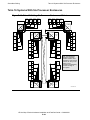
Group, Module, and Slot Hierarchy for System Enclosures 1-26
Group, Module, and Slot Hierarchy for IOAM Enclosures 1-28
Server Numbering and Labeling 1-31
ServerNet Cabling 1-35
System Size 1-35
Topologies 1-36
Fabrics and Slots 1-36
IOAM Enclosure Cabling 1-37
ServerNet Cables 1-37
The System Console 1-45
System Consoles 1-45
The OSM Product 1-46
The TSM Package 1-46
Primary and Backup System Consoles 1-47
Modems 1-48
Preloaded and Supported Hardware and Software 1-49
Software Connections 1-54
System Startup 1-55
Startup and Shutdown Files 1-55
System Load Paths 1-55
PMF CRU and IOMF CRU Power-On Self-Tests 1-57
2. Installing Enclosures
Prepare to Install New Equipment 2-2
1. Review the Documentation 2-2
2. Prepare the Work Space 2-3
3. Organize the Equipment 2-4
Unpack the Enclosures 2-6
Tools 2-6
Unpack the Enclosures 2-6
Connect the Groundstraps 2-13
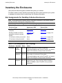
Inventory the Enclosures 2-16
Slot Assignments for NonStop S-Series Enclosures
Inspect the Components 2-23
2-16
HP NonStop S-Series Hardware Installation and FastPath Guide —541880-001
ii
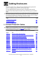
3. Cabling Enclosures
Contents
3. Cabling Enclosures
1. Connect Power-On Cables 3-1
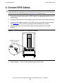
2. Connect EPO Cables 3-4
3. Connect ServerNet Cables 3-5
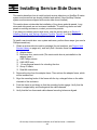
4. Installing Service-Side Doors
5. Installing, Starting, and Testing a System Console
Unpacking and Assembling a System Console 5-2
Installation Quick Reference 5-2
Finding Documentation 5-2
Finding the Quick Setup Reference Card 5-2
Unpacking the System Console 5-2
Assembling the System Console 5-6
Starting and Testing a System Console 5-8
Powering On a System Console 5-8
Verifying Readiness 5-9
Final Setup Steps 5-9
Operational Considerations for OSM and TSM 5-10
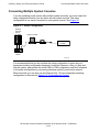
Connecting Multiple System Consoles 5-11
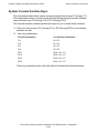
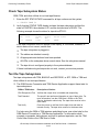
System Console Function Keys 5-12
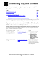
6. Connecting a System Console
The Dedicated Service LAN 6-2
Server Connection to a LAN 6-2
System Console Connection to a Dedicated Service LAN 6-3
System Console Connection to a Secure Operations LAN 6-4
Ethernet Cables 6-4
Ethernet Switch Ports 6-4
Installing Ferrite Cores 6-4
Installing the Ethernet Switch or Hub 6-5
Connect the Ethernet Switch or Hub to the Server 6-5
Connect the System Console to the Ethernet Switch or Hub 6-6
HP NonStop S-Series Hardware Installation and FastPath Guide —541880-001
iii
7. Installing External System Devices
Contents
7. Installing External System Devices
Installing Tape Drives 7-1
Installing a 5175 Open-Reel Tape Subsystem 7-2
Installing a 519x Cartridge Tape Subsystem 7-8
Installing Other Tape Devices 7-12
Installing Fibre Channel Tape Devices Using an IOAM Enclosure 7-15
Attaching a SCSI Tape Drive to the NonStop S-Series Server 7-15
Installing a SWAN or SWAN 2 Concentrator 7-16
Installing an AWAN Server 7-17
Installing Printers and Terminals 7-17
8. Powering On and Starting the System
Starting a System for the First Time 8-2
Startup Checklist 8-2
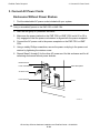
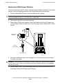
Powering On External System Devices 8-3
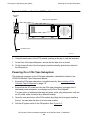
Powering On the Primary System Console and Modem
Powering On the Tape Subsystem 8-3
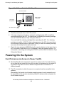
Powering On the System 8-5
Fault Tolerance and Access to Power Cutoffs 8-5
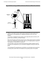
Power-On Procedure Using AC Power Cords 8-6
Status LEDs During a Power-On Procedure 8-10
Troubleshooting Abnormal LED States 8-12
Verifying Topology and System Components 8-14
Starting the System 8-18
Loading the System 8-18
Completing the System Load 8-21
Verifying the System Is Started 8-21
8-3
9. Performing Post-Startup Tasks
Testing the System 9-1
Check Power Supplies 9-2
Check System Enclosure Components 9-2
Check Critical System Processes 9-6
Check Disk Subsystem Status 9-7
Test the Disk Drives 9-8
Test the Communications Lines 9-10
Check Tape Subsystem Status 9-11
Test the Tape Subsystems 9-11
HP NonStop S-Series Hardware Installation and FastPath Guide —541880-001
iv
9. Performing Post-Startup Tasks (continued)
Contents
9. Performing Post-Startup Tasks (continued)
Completing Final Installation Steps 9-12
System Configuration Changes and Verifications
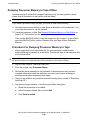
Restarting the Inspect Monitor Process 9-14
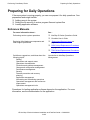
Preparing for Daily Operations 9-15
Reference Manuals 9-15
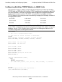
Configuring the OSM or TSM Environment 9-16
Configuring the OSM Environment 9-16
Configuring the TSM Environment 9-16
9-13
10. Configuring the System
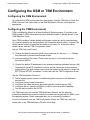
Setup Configuration 10-2
Procedure to Create the Setup Configuration 10-2
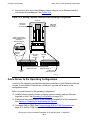
Operating Configuration 10-3
Create the Operating Configuration 10-3
Add a System Console to the Operating Configuration 10-6
Add a Server to the Operating Configuration 10-8
Create a Cascading Ethernet Switch Configuration 10-10
Add a System Console to the Cascading Ethernet Switches 10-12
Add a Server to the Cascading Ethernet Switches 10-12
Unattended Site Configuration 10-13
Create the Unattended Site Configuration 10-13
Add a Server to an Unattended Site Configuration 10-14
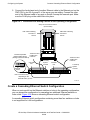
Secure Operations LAN Configuration 10-15
Construct a Secure Operations LAN Configuration 10-15
11. Offline Configuration Tasks
Changes That Must Be Made Offline 11-1
Application Reconfiguration 11-2
Installing a New RVU 11-2
Installing a Product Revision 11-2
Changing System Name, System Number, or Time Attributes
Changing the System Topology 11-3
Changing the CONFTEXT File 11-3
11-3
HP NonStop S-Series Hardware Installation and FastPath Guide —541880-001
v
12. Online Configuration Tasks
Contents
12. Online Configuration Tasks
SCF 12-2
Initial CONFIG file 12-2
Subsystems in G-Series RVUs 12-3
Generic Processes 12-4
Making Important Processes Persistent 12-5
Types of System Configuration Files 12-6
KMSF 12-8
Initial Configuration of KMSF Swap Files 12-8
Changing the Configuration of KMSF Swap Files 12-8
KMSF and the Operations Environment 12-8
The OSM and TSM Packages 12-9
Creating an Alternate System Disk 12-10
1. Choose the Target Disk and Plan Its Space and Files 12-11
2. Verify That the Target Disk Is Present 12-12
3. Stop Access to the Target Disk and Display Its Status 12-12
4. Change the Label of the Target Disk 12-13
5. Create a New System Volume and a System Image Tape (SIT) 12-14
6. Install the Boot Millicode on the Target Disk 12-14
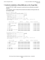
7. Verify the Installation of Boot Millicode on the Target Disk 12-15
8. Copy Subvolumes to the Target Disk 12-16
Create a Command File 12-17
13. Creating Startup and Shutdown Files
Automating System Startup and Shutdown 13-2
Startup 13-2
Shutdown 13-2
For More Information 13-2
Processes That Represent the System Console 13-3
$YMIOP.#CLCI 13-3
$YMIOP.#CNSL 13-3
$ZHOME 13-3
$ZHOME Alternative 13-4
Example Command Files 13-5
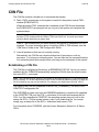
CIIN File 13-6
Establishing a CIIN File 13-6
Modifying a CIIN File 13-7
If a CIIN File Is Not Specified or Enabled in OSM or TSM
Example CIIN Files 13-8
13-7
HP NonStop S-Series Hardware Installation and FastPath Guide —541880-001
vi
Contents
13. Creating Startup and Shutdown
Files (continued)
13. Creating Startup and Shutdown Files (continued)
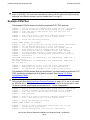
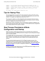
Tips for Startup Files 13-9
How Process Persistence Affects Configuration and Startup
Startup File Examples 13-10
System Startup File 13-10
Spooler Warm-Start File 13-12
TMF Warm-Start File 13-12
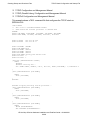
TCP/IP Stack Configuration and Startup File 13-12
CP6100 Lines Startup File 13-15
ATP6100 Lines Startup File 13-15
X.25 Lines Startup File 13-15
Printer Line Startup File 13-16
Expand-Over-IP Line Startup File 13-16
Expand Direct-Connect Line Startup File 13-16
Tips for Shutdown Files 13-17
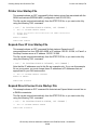
Shutdown File Examples 13-17
System Shutdown File 13-18
CP6100 Lines Shutdown File 13-19
ATP6100 Lines Shutdown File 13-19
X.25 Lines Shutdown File 13-19
Printer Line Shutdown File 13-20
Expand-Over-IP Line Shutdown File 13-20
Direct-Connect Line Shutdown File 13-20
Spooler Shutdown File 13-21
TMF Shutdown File 13-21
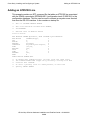
Adding Super-Group User IDs 13-21
13-9
14. Case Study: Installing and Configuring a System
About These Examples 14-2
Background for Developers Inc. 14-3
Hardware Configuration 14-4
Installation Documents 14-4
Case Study: Installation Document Checklist 14-5
Case Study: System Equipment Inventory Form 14-6
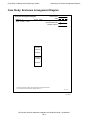
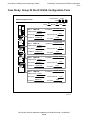
Case Study: Enclosure Arrangement Diagram 14-7
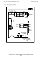
Case Study: Floor Plan 14-8
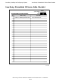
Case Study: Preinstalled I/O Device Cable Checklist 14-9
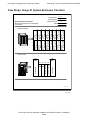
Case Study: Group 01 System Enclosure Checklist 14-10
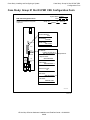
Case Study: Group 01 Slot 50 PMF CRU Configuration Form
14-11
HP NonStop S-Series Hardware Installation and FastPath Guide —541880-001
vii
14. Case Study: Installing and Configuring a
System (continued)
Contents
14. Case Study: Installing and Configuring a System (continued)
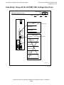
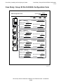
Case Study: Group 01 Slot 55 PMF CRU Configuration Form 14-12
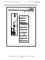
Case Study: Group 01 Slot 53 E4SA Configuration Form 14-13
Case Study: Group 01 Slot 54 E4SA Configuration Form 14-14
Case Study: Group 02 System Enclosure Checklist 14-15
Case Study: Group 02 Slot 50 PMF CRU Configuration Form 14-16
Case Study: Group 02 Slot 55 PMF CRU Configuration Form 14-17
Case Study: Group 02 Slot 53 E4SA Configuration Form 14-18
Case Study: Group 02 Slot 54 E4SA Configuration Form 14-19
System Configuration: CONFTEXT File 14-20
LAN Environment at Developers Inc. 14-20
Registry of IP Addresses 14-20
Installing the System 14-22
Customizing the Configuration 14-22
Adding Ethernet 4 ServerNet Adapters (E4SAs) 14-23
Adding ConMgr Process 14-24
Configuring NonStop TCP/IP Stacks on E4SA Ports 14-25
Adding Persistent CLCI TACL, Expand Manager, and SCP Processes
Starting the $ZEXP Expand Manager Process 14-27
Adding a SWAN Concentrator 14-28
Adding a SWAN 2 Concentrator 14-28
Adding CP6100 Lines 14-29
Adding an ATP6100 Line 14-30
Adding a 5516 Printer 14-31
Adding an X.25 Line 14-32
Configuring and Starting the $NCP Network Control Process 14-33
Adding an Expand-Over-IP Line 14-33
Adding a Direct-Connect Line 14-34
A. Part Numbers
HP NonStop S-Series Hardware Installation and FastPath Guide —541880-001
viii
14-27
B. ServerNet Cabling
Contents
B. ServerNet Cabling
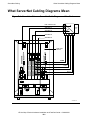
What ServerNet Cabling Diagrams Mean B-2
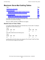
Maximum ServerNet Configurations B-4
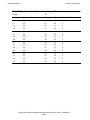
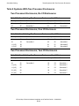
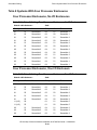
Maximum ServerNet Cabling Tables B-7
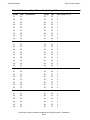
Shaded Areas in These Tables B-7
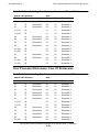
Tetra 8 Cabling Tables B-8
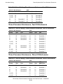
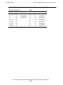
Tetra 16 Cabling Tables B-10
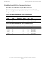
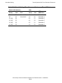
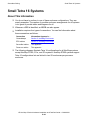
Small Tetra 8 Systems B-14
About This Information B-14
Tetra 8 Systems With One Processor Enclosure B-15
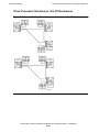
Tetra 8 Systems With Two Processor Enclosures B-16
Tetra 8 Systems With Three Processor Enclosures B-17
Tetra 8 Systems With Four Processor Enclosures B-21
Small Tetra 16 Systems B-25
About This Information B-25
Tetra 16 Systems With Four Processor Enclosures B-26
Tetra 16 Systems With Six Processor Enclosures B-28
C. Power-On Cabling
D. Troubleshooting
Reference D-2
Power States D-2
Status LEDs D-4
Powering On the System D-5
System Does Not Appear to Be Powered On D-6
Power Is Applied to Enclosure But Fans Are Not Turning D-6
Any Green LED Is Not Lit D-8
Any Amber LED Remains Lit After POST D-9
Yellow ServerNet Port LEDs on SEBs or MSEBs Are Not Lit D-9
Group Service LED on System Enclosure Is Flashing D-9
Correcting Topology Attribute D-9
HP NonStop S-Series Hardware Installation and FastPath Guide —541880-001
ix
D. Troubleshooting (continued)
Contents
D. Troubleshooting (continued)
Starting the System D-10
Startup Event Stream and Startup TACL Windows Do Not Appear
System Load Fails D-11
CIIN File Is Not Invoked During System Startup D-12
Reload Fails D-13
CPU Memory Test Fails D-14
System Load Path Test Fails D-14
Multifunction I/O Board (MFIOB) Test Fails D-15
Dumping Processor Memory D-16
Dumping Processor Memory to Disk Online D-16
Dumping Processor Memory to Tape Offline D-20
Expand-Over-IP Connections D-22
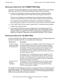
Recovery Actions for the CONNECTING State D-24
Recovery Actions for the WAIT State D-24
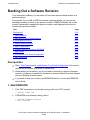
Backing Out a Software Revision D-26
Prerequisites D-26
1. Start DSM/SCM D-26
2. Start and Log On to Target Interface D-27
3. Initiate Backout Activity D-27
4. Monitor Backout Process D-28
5. Stop All Applications D-28
6. Rename Software Files Using ZPHIRNM D-29
7. Stop System D-29
8. Load System From Saved Configuration D-30
9. Start Applications D-30
System Consoles D-31
Software Configuration Problems D-36
Software Corruption and Hard-Disk Problems D-37
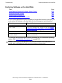
Restoring Software on the Hard Disk D-38
Configuring a ProCurve 24-Port Ethernet Switch D-48
D-10
HP NonStop S-Series Hardware Installation and FastPath Guide —541880-001
x
E. FastPath Tasks: Required
Contents
E. FastPath Tasks: Required
1. Install Hardware E-3
1. Inventory Shipment E-4
2. Collect Tools E-6
3. Unpack and Unload Server E-6
4. Connect Groundstraps E-10
5. Inventory and Inspect All Components E-11
6. Connect the Power-On Cables E-11
7. Connect Emergency Power-Off (EPO) Cables E-13
8. Connect ServerNet Cables E-14
9. Install Service-Side Enclosure Doors If Necessary E-15
10. Install Primary System Console E-16
11. Create Emergency Repair Disk or Automated System Recovery Disk
12. Install Ethernet Switch E-18
13. Connect Ethernet Switch to Group 01 E-18
14. Connect Primary System Console to Ethernet Switch E-19
15. Install Tape Drive E-19
2. Start the System E-22
1. Prepare for System Startup E-22
2. Power On External System Devices E-23
3. Connect AC Power Cords E-24
4. Apply Power to Server E-26
5. Verify Topology E-27
6. Verify System Components E-28
7. Start System E-28
3. Verify the System E-30
1. Verify Components E-30
2. Verify Critical System Processes E-31
3. Verify Disk Drives E-31
4. Verify Tape Drive E-32
5. Verify Firmware E-32
6. Verify State of the Internal ServerNet Fabric E-32
4. Configure the System E-33
1. Configure Passwords E-34
2. Configure Kernel-Managed Swap Files E-35
3. Configure OSM or TSM Environment E-36
4. Configure System Attributes E-37
5. Configure DSM/SCM E-41
5. Install the Backup System Console E-45
HP NonStop S-Series Hardware Installation and FastPath Guide —541880-001
xi
E-18
F. FastPath Tasks: Optional
Contents
F. FastPath Tasks: Optional
1. Prerequisites F-2
1a. Verify Required Configuration Changes F-2
1b. Review Initial System Configuration F-2
1c. Start Required Processes F-2
1d. Save Current System Configuration F-3
1e. If Your Server Will Be Part of a ServerNet Cluster
2. Customize the System Configuration F-4
2a. Change SCF F-4
2b. Rename SCF Objects in the CONFIG File F-5
2c. Add SCF Objects to the CONFIG File F-6
3. Automate System Startup F-7
Modify Provided Startup Files F-7
Create Startup Files F-7
4. Automate System Shutdown F-8
Tips for Shutdown Files F-8
5. Configure a SWAN or SWAN 2 Concentrator F-9
Access the WAN Wizard Pro F-9
6. Configure an Expand-Over-IP Line F-10
Prerequisites F-11
1. On the NonStop S-Series Server F-12
2. On the NonStop K-Series Server F-16
3. On the NonStop S-Series Server F-18
4. On the NonStop K-Series Server F-19
5. On Either NonStop Server F-21
7. Install Software F-22
Configuring Software With DSM/SCM F-23
Installing a Software Product Revision (SPR) F-25
F-3
Safety and Compliance
Glossary
Index
HP NonStop S-Series Hardware Installation and FastPath Guide —541880-001
xii
Examples
Contents
Examples
Example D-1.
Example F-1.
Example F-2.
Example F-3.
Example F-4.
Example F-5.
Example F-6.
Example F-7.
Example F-8.
Example F-9.
SCF STATUS LINE, DETAIL Display D-22
SCF LISTDEV TCPIP Display F-13
SCF LISTDEV TCP6SAM Display F-14
SCF INFO SUBNET Display F-14
SCF STATUS PROCESS Display F-15
SCF LISTDEV TCPIP Display F-16
SCF INFO SUBNET Display F-16
SCF STATUS PROCESS Display F-17
COUP INFO CONTROLLER Display F-19
COUP INFO DEVICE Display F-19
Figures
Figure 1-1.
Figure 1-2.
Figure 1-3.
Figure 1-4.
Figure 1-5.
Figure 1-6.
Figure 1-7.
Figure 1-8.
Figure 1-9.
Figure 1-10.
Figure 1-11.
Figure 1-12.
Figure 1-13.
Figure 1-14.
Figure 1-15.
Figure 1-16.
Figure 1-17.
Figure 1-18.
Figure 1-19.
Figure 1-20.
Figure 1-21.
Figure 1-22.
Figure 2-1.
Figure 2-2.
Figure 2-3.
Figure 2-4.
The Shipping Package 1-10
Shipping Package Dimensions 1-11
Base and Stackable Enclosures 1-16
SEBs in a Processor Enclosure Without a Power Shelf 1-17
MSEBs in a Processor Enclosure With a Power Shelf 1-18
Service Side of I/O Enclosure Without Power Shelf 1-19
Service Side of I/O Enclosure With Power Shelf 1-20
Rack with IOAM Enclosure (Front Side) 1-21
Rack With IOAM Enclosure (Rear Side) 1-22
Power-On Cable Connectors 1-24
EPO Cable 1-25
Port Numbers and Cable Connections on an MSEB 1-39
SEB-to-SEB ECL Cable 1-40
MSEB-to-MSEB ECL Cable 1-40
SEB-to-MSEB ECL Cable 1-40
Serial-Copper Cable 1-41
Fiber-Optic Cable 1-41
LC Connector for the 6780 Switch or ServerNet Switch Board 1-42
SC Connector for MSEB 1-42
ServerNet Cable Labeling 1-43
Cable-Management Hardware 1-44
System Load Paths 1-56
Cords, Cables, and Other Contents of Short Cartons 2-5
Unpacking the Enclosures 2-7
Tabs on Plastic Locking Clip of Shipping Package 2-8
Loosen End Piece of Pallet by Turning Twist-Lock Handles 2-8
HP NonStop S-Series Hardware Installation and FastPath Guide —541880-001
xiii
Figures (continued)
Contents
Figures (continued)
Figure 2-5.
Figure 2-6.
Figure 2-7.
Figure 2-8.
Figure 2-9.
Figure 2-10.
Figure 2-11.
Figure 2-12.
Figure 2-13.
Figure 2-14.
Figure 2-15.
Figure 2-16.
Figure 2-17.
Figure 2-18.
Figure 2-19.
Figure 2-20.
Figure 2-21.
Figure 2-22.
Figure 3-1.
Figure 3-2.
Figure 3-3.
Figure 4-1.
Figure 4-2.
Figure 4-3.
Figure 4-4.
Figure 5-1.
Figure 6-1.
Figure 6-2.
Figure 7-1.
Figure 7-2.
Figure 7-3.
Figure 7-4.
Figure 7-5.
Figure 7-6.
Figure 7-7.
Figure 7-8.
Figure 8-1.
Removing End Piece of Pallet 2-9
Velcro Strips on Loading Pallet 2-9
Leveling Pads Must Be Raised Before Enclosure Is Moved 2-10
Use Two People to Move an Enclosure Stack 2-11
Lowering Legs of Base Enclosure 2-12
Groundstrap Connector Locations 2-13
Groundstrap Connections Between Enclosures 2-14
Examples of Groundstrap Locations Between Enclosures 2-15
Appearance Side, Processor Enclosure 2-17
Service Side: Processor Enclosure Without Power Shelf 2-18
Service Side: Processor Enclosure With Power Shelf 2-19
Service Side: I/O Enclosure Without Power Shelf 2-20
Service Side: I/O Enclosure With Power Shelf 2-21
Unlocking and Opening an Enclosure Door 2-22
Reseating a Disk Drive 2-23
Reseating a PMF CRU or IOMF CRU 2-24
Reseating a SEB or MSEB 2-25
Reseating a ServerNet Adapter 2-26
Connecting and Securing Power-On Cables 3-3
EPO Connector on a System Enclosure 3-4
Securing ServerNet Cables With Cable Ties 3-6
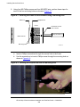
Securing the Frame to the Enclosure Using a Mounting Hole 4-2
Inserting a Phillips Screw Into the Mounting Hole 4-2
Tightening a Phillips Screw in a Mounting Hole 4-3
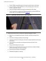
Service-Side Door Installed on a System Enclosure 4-4
Setup Configuration 5-11
Processor Enclosure PMF CRU Ethernet Ports 6-3
Connections for the Setup Configuration 6-6
5175 Tape Subsystem 7-2
Unloading a Tape Subsystem 7-3
Removing the Shipping Restraints From a 5175 Tape Subsystem 7-5
Installing the Top Panel and Corner Caps on a 5175 Tape
Subsystem 7-6
Connecting a SCSI Cable to a 5175 Tape Subsystem 7-7
AC Power Switch for 5175 Tape Drive CRU 7-8
519x Tape Subsystem 7-9
Connecting a SCSI Cable to a 519x Tape Subsystem 7-10
AC Power Switch for 5175 Tape Drive 8-4
HP NonStop S-Series Hardware Installation and FastPath Guide —541880-001
xiv
Figures (continued)
Contents
Figures (continued)
Figure 8-2.
Figure 8-3.
Figure 8-4.
AC Power Switch for 519x Tape Drive 8-5
AC Power Cord 8-6
Connecting an AC Power Cord to an Enclosure With No Power
Shelf 8-7
Figure 8-5.
Connecting an AC Power Cord to an Enclosure With a Power
Shelf 8-8
Figure 8-6.
Management Window in OSM or TSM Low-Level Link 8-15
Figure 8-7.
Verifying the System Topology 8-15
Figure 8-8.
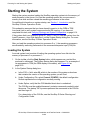
Entering Information in the System Startup Dialog Box 8-19
Figure 8-9.
Checking Processor Status 8-22
Figure 9-1.
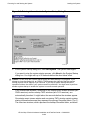
Management Window in the OSM Service Connection 9-3
Figure 9-2.
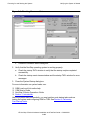
Management Window in the TSM Service Application 9-4
Figure 10-1. Setup Configuration 10-2
Figure 10-2. Operating Configuration 10-3
Figure 10-3. Connections for the Operating Configuration 10-5
Figure 10-4. Operating Configuration With an Added System Console 10-6
Figure 10-5. Adding a System Console to the Operating Configuration 10-8
Figure 10-6. Operating Configuration With an Added Server 10-9
Figure 10-7. Connections for Adding a Server to the Operating Configuration 10-10
Figure 10-8. Cascading Ethernet Switch Configuration 10-11
Figure 10-9. Connecting Cascading Ethernet Switches 10-12
Figure 10-10. Unattended Site Configuration 10-13
Figure 10-11. LAN Configurations: Operations and Dedicated 10-16
Figure 12-1. Subsystems in G-Series RVUs 12-3
Figure 12-2. Differences Among System Configuration Files 12-7
Figure B-1.
Correlation Between ServerNet Cable Diagram and One
Enclosure B-2
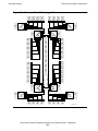
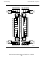
Figure B-2.
Correlation Between ServerNet Cable Diagram and Two
Enclosures B-3
Figure B-3.
Maximum Tetra 8 Topologies, X and Y Fabrics B-4
Figure B-4.
Maximum Tetra 16 Topology, X Fabric B-5
Figure B-5.
Maximum Tetra 16 Topology, Y Fabric B-6
Figure B-6.
Tetra 8 Cabling: Two Processor Enclosures, Two I/O Enclosures B-17
Figure B-7.
Tetra 8 Cabling: Three Processor Enclosures, Six I/O Enclosures B-20
Figure B-8.
Tetra 16 Cabling: Four Processor Enclosures, X Fabric B-26
Figure B-9.
Tetra 16 Cabling: Four Processor Enclosures, Y Fabric B-27
Figure B-10. Tetra 16 Cabling: Six Processor Enclosures, X Fabric B-28
Figure B-11. Tetra 16 Cabling: Six Processor Enclosures, Y Fabric B-29
HP NonStop S-Series Hardware Installation and FastPath Guide —541880-001
xv
Figures (continued)
Contents
Figures (continued)
Figure C-1.
Figure C-2.
Figure C-3.
Figure C-4.
Figure C-5.
Figure C-6.
Figure C-7.
Figure C-8.
Figure C-9.
Figure C-10.
Figure C-11.
Figure C-12.
Figure C-13.
Figure C-14.
Figure C-15.
Figure C-16.
Figure C-17.
Figure C-18.
Figure E-1.
Figure E-2.
Figure E-3.
Figure E-4.
Figure E-5.
Figure E-6.
Figure E-7.
Figure E-8.
Figure E-9.
Figure E-10.
Figure E-11.
Power-On Cabling: Single-High Stacks C-2
Power-On Cabling: Mixed Single-High and Double-High Stacks C-3
Power-On Cabling: Multiple-Row Systems C-4
Power-On Cable: One Processor Enclosure C-5
Power-On Cables: One Processor Enclosure, One I/O Enclosure C-5
Power-On Cables: One Processor Enclosure, Two I/O Enclosures C-5
Power-On Cables: Two Processor Enclosures, No I/O Enclosures C-6
Power-On Cables: Two Processor Enclosures, One I/O Enclosure C-6
Power-On Cables: Two Processor Enclosures, Two I/O
Enclosures C-6
Power-On Cables: Three Processor Enclosures, No I/O
Enclosures C-7
Power-On Cables: Three Processor Enclosures, One I/O
Enclosure C-7
Power-On Cables: Three Processor Enclosures, Two I/O
Enclosures C-7
Power-On Cables: Three Processor Enclosures, Three I/O
Enclosures C-8
Power-On Cables: Four Processor Enclosures, No I/O Enclosures C-8
Power-On Cables: Four Processor Enclosures, One I/O Enclosure C-8
Power-On Cables: Four Processor Enclosures, Two I/O
Enclosures C-8
Power-On Cables: Four Processor Enclosures, Three I/O
Enclosures C-9
Power-On Cables: Four Processor Enclosures, Four I/O
Enclosures C-9
Packaging of Enclosure Stack E-6
Velcro Strips on Loading Pallet E-8
Rolling the Stack to the Installation Area E-9
Enclosure Stacks in Final Positions E-9
Lowering Legs of Base Enclosure E-9
Groundstrap Connector Locations E-10
Power-On Cable Connectors E-11
Power-On Cables: One Processor Enclosure E-11
Power-On Cables: One Processor Enclosure, One I/O Enclosure E-11
Power-On Cables: One Processor Enclosure, Two I/O
Enclosures E-12
Power-On Cables: Two Processor Enclosures E-12
HP NonStop S-Series Hardware Installation and FastPath Guide —541880-001
xvi
Figures (continued)
Contents
Figures (continued)
Figure E-12.
Figure E-13.
Figure E-14.
Figure E-15.
Figure E-16.
Figure E-17.
Power-On Cables: Two Processor Enclosures, One I/O
Enclosure E-12
Power-On Cables: Two Processor Enclosures, Two I/O
Enclosures E-12
EPO Cable E-13
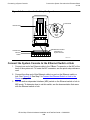
Connecting an Ethernet Switch to Group 01 E-18
Attaching SCSI Cable to PMF CRU E-20
Adding a System Console to the Operating Configuration
E-46
Tables
Table 1-1.
Table 1-2.
Table 1-3.
Table 1-4.
Table 1-5.
Table 1-6.
Table 1-7.
Table 2-1.
Table 2-2.
Table 2-3.
Table 5-1.
Table 7-1.
Table 8-1.
Table 8-2.
Table 8-3.
Table 9-1.
Table B-1.
Table B-2.
Table B-3.
Table B-4.
Table B-5.
Table B-6.
Table B-7.
Table B-8.
Table B-9.
Table B-10.
Table B-11.
Weights for Enclosure Shipping Packages 1-10
Maximum Processor and I/O or IOAM Enclosure Connections 1-31
Maximum Numbers of Enclosures for G06.03 and Later RVUs 1-35
ServerNet Cable Compatibilities With Components 1-38
Preloaded and Supported HP NonStop System Console
Software 1-50
Preconfigured IP Addresses for a NonStop S-Series Server 1-52
System Load Paths in Order of Use 1-55
Illustrations of Enclosures Including Slot Numbers 2-16
Slot Assignments: Tetra 8 Topology 2-16
Slot Assignments: Tetra 16 Topology 2-17
Contents of the Shipping Box 5-3
517x Firmware Requirements 7-3
Status LEDs and Their Functions 8-10
Troubleshooting Abnormal LED States 8-12
Checking the Attributes of Selected System Components 8-16
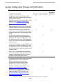
System Configuration Changes and Verifications 9-13
Maximum Tetra 8 ServerNet Cabling, Processor Enclosures B-8
Maximum Tetra 8 ServerNet Cabling, I/O Enclosures B-9
Maximum Tetra 16 ServerNet Cabling, Processor Enclosures B-10
Maximum Tetra 16 ServerNet Cabling, I/O Enclosures B-11
Tetra 8 Cabling: One Processor Enclosure, One I/O Enclosure B-15
Tetra 8 Cabling: One Processor Enclosure, Two I/O Enclosures B-15
Tetra 8 Cabling: Two Processor Enclosures, No I/O Enclosures B-16
Tetra 8 Cabling: Two Processor Enclosures, One I/O Enclosure B-16
Tetra 8 Cabling: Two Processor Enclosures, Two I/O Enclosures B-16
Tetra 8 Cabling: Three Processor Enclosures, No I/O Enclosures B-17
Tetra 8 Cabling: Three Processor Enclosures, One I/O Enclosure B-17
HP NonStop S-Series Hardware Installation and FastPath Guide —541880-001
xvii
Tables (continued)
Contents
Tables (continued)
Table B-12.
Table B-13.
Table B-14.
Table B-15.
Table B-16.
Table B-17.
Table B-18.
Table D-1.
Table D-2.
Table D-3.
Table D-4.
Table D-5.
Table D-6.
Table D-7.
Table D-8.
Table D-9.
Table D-10.
Table D-11.
Table E-1.
Table E-2.
Table E-3.
Table E-4.
Table F-1.
Table F-2.
Tetra 8 Cabling: Three Processor Enclosures, Two I/O
Enclosures B-18
Tetra 8 Cabling: Three Processor Enclosures, Three I/O
Enclosures B-18
Tetra 8 Cabling: Four Processor Enclosures, No I/O Enclosures B-21
Tetra 8 Cabling: Four Processor Enclosures, One I/O Enclosure B-21
Tetra 8 Cabling: Four Processor Enclosures, Two I/O Enclosures B-22
Tetra 8 Cabling: Four Processor Enclosures, Three I/O
Enclosures B-22
Tetra 8 Cabling: Four Processor Enclosures, Four I/O Enclosures B-23
Troubleshooting the Expand Connection Procedure D-22
Keyboard Is Inoperative D-32
Mouse Is Inoperative D-33
Monitor Screen Is Blank D-34
System Unit Is Inoperative D-35
Monitor Screen Is Frozen D-36
Application Fails Immediately When Started D-37
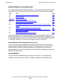
Install Windows XP Professional Operating System D-39
Set Up Date and Time D-43
Set Event Log Settings D-44
Install Internet Explorer D-46
ServerNet Cables for One Processor Enclosure, One I/O
Enclosure E-14
ServerNet Cables for Two Processor Enclosures, No I/O
Enclosures E-14
ServerNet Cables for Two Processor Enclosures, One I/O
Enclosure E-14
ServerNet Cables for Two Processor Enclosures, Two I/O
Enclosures E-15
SCF ADD DEVICE Command Worksheet F-18
COUP Worksheet F-20
HP NonStop S-Series Hardware Installation and FastPath Guide —541880-001
xviii
What’s New in This Guide
Manual Information
HP NonStop S-Series Hardware Installation and FastPath Guide
Abstract
This guide is written for anyone qualified to install an HP NonStop™ S-series server.
This guide describes how to install and start a NonStop S-series server for the first
time. It includes information about installing server hardware, cabling system
enclosures, installing and starting NonStop system consoles, installing external system
devices, starting the server, and configuring the server after startup. This guide also
provides overview information about the I/O adapter module (IOAM) enclosure. A
quick reference to installing and configuring a two-processor or four-processor
NonStop S-series server in the Tetra 8 topology is included.
Product Version
N.A.
Supported Release Version Updates (RVUs)
This publication supports G06.28 and all subsequent G-series RVUs until otherwise
indicated by its replacement publication.
Part Number
Published
541880-001
February 2006
Document History
Part Number
Product Version
Published
528858-001
N.A.
September 2004
529443-001
N.A.
December 2004
529876-001
N.A.
April 2005
540460-001
N.A.
September 2005
541880-001
N.A.
February 2006
HP NonStop S-Series Hardware Installation and FastPath Guide —541880-001
xix
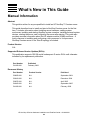
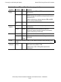
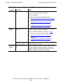
New and Changed Information
What’s New in This Guide
New and Changed Information
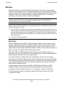
This publication has been updated to include information about:
•
•
Disk-drive enclosures (also known as Fibre Channel disk modules (FCDMs)). Diskdrive enclosures are connected to Fibre Channel ServerNet adapters (FCSAs)
installed in IOAM enclosures.
The M8520 mid-range tape library. M8520 tape libraries requires N1522A tape
drives.
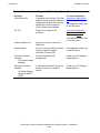
Section
Title
Manual-wide
7
Changes
Editorial corrections.
Installing External
System Devices
Added a new subsection for Installing Fibre
Channel Tape Devices Using an IOAM Enclosure
on page 7-15.
Safety and
Compliance
Updated for G06.28 RVU.
Glossary
The glossary has been moved to NTL and is titled
NonStop System Glossary.
HP NonStop S-Series Hardware Installation and FastPath Guide —541880-001
xx
About This Guide
This guide describes how to install and bring up a NonStop S-series server for the first
time. It includes information about installing the server hardware, cabling system
enclosures, installing and starting system consoles, installing external system devices,
and starting the server. This guide is written for anyone who is qualified to install a
NonStop S-series server.
This guide assumes that you are using the HP NonStop Open System Management
(OSM) or Compaq TSM software to perform the OSM or TSM tasks described in this
guide.
Note. Throughout this guide, the term Sxx000 stands for NonStop S70000, S72000, S74000,
S76000, S78000, S86000, S88000 servers.
Information in this guide also applies to NonStop S7x00 servers of model S7400 and higher.
Who Should Use This Guide
This guide is written for anyone who installs system equipment at a customer site. You
should be familiar with computers but do not need to be familiar with installing
mainframe computer systems. However, those who perform the hardware tasks
documented in this guide must have completed training courses on system support for
NonStop S-series servers.
Note. NonStop NS-series, NonStop S-series, and NonStop K-series refer to hardware
systems; H-series, G-series, and D-series refer to system software.
•
•
•
H-series software runs on NonStop NS-series servers.
G-series software runs on NonStop S-series servers.
D-series software runs on NonStop K-series servers.
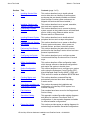
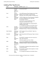
What’s in This Guide
Section
Title
Contents (page 1 of 3)
1
Introduction
This section summarizes the installation process and
gives an overview of the NonStop S-series system.
2
Installing Enclosures
This section describes how to unpack new
equipment and install NonStop system enclosures.
3
Cabling Enclosures
This section explains how to cable enclosures in
NonStop S-series systems with power-on,
emergency power-off (EPO), and ServerNet cables.
HP NonStop S-Series Hardware Installation and FastPath Guide —541880-001
xxi
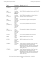
What’s in This Guide
About This Guide
Section
Title
Contents (page 2 of 3)
4
Installing Service-Side
Doors
This section describes how to install optional
service-side doors on NonStop S-series system
enclosures that are already installed and cabled.
(New NonStop S-series system enclosures are
shipped with service-side doors installed.)
5
Installing, Starting, and
Testing a System Console
This section describes how to unpack, assemble,
start, and test a system console.
6
Connecting a System
Console
This section describes how to connect a primary
system console to the installed server and dedicated
service LAN by using Ethernet cables and an
Ethernet switch or Ethernet hub.
7
Installing External System
Devices
This section describes how to install selected
peripheral devices such as tape subsystems.
8
Powering On and Starting
the System
This section describes how to power on NonStop
S-series system enclosures, how to power on
external devices, and how to start the system.
9
Performing Post-Startup
Tasks
This section describes the tasks that you must
perform after the NonStop S-series server has been
powered up and started.
10
Configuring the System
This section describes how to configure system
consoles and NonStop S-series servers in several
ways.
11
Offline Configuration
Tasks
This section describes offline configuration tasks,
which change software or hardware configurations
and require the system to be shut down.
12
Online Configuration
Tasks
This section describes how to configure your system
online using the Subsystem Control Facility (SCF),
Kernel-Managed Swap Facility (KMSF), OSM, and
TSM, and how to create an alternate $SYSTEM disk.
13
Creating Startup and
Shutdown Files
This section describes command files that
automatically start and shut down a NonStop
S-series server.
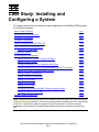
14
Case Study: Installing and
Configuring a System
This section documents the installation and
configuration of a NonStop S7000 system for a
fictitious company.
A
Part Numbers
Part numbers have been moved to the Support and
Service Library.
B
ServerNet Cabling
This appendix contains ServerNet cabling diagrams
and tables for maximum Tetra 8 and Tetra 16
configurations. It also contains diagrams and tables
for selected smaller configurations.
C
Power-On Cabling
This section provides power-on cabling diagrams for
selected large and smaller ServerNet configurations.
HP NonStop S-Series Hardware Installation and FastPath Guide —541880-001
xxii
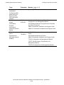
What’s in This Guide
About This Guide
Section
Title
Contents (page 3 of 3)
D
Troubleshooting
This appendix explains basic recovery tasks for the
system and system console.
E
FastPath Tasks: Required
This appendix contains all the tasks required to
install, start, and configure a two-processor or fourprocessor NonStop S-series server in the Tetra 8
topology.
F
FastPath Tasks: Optional
This appendix contains all optional configuration
tasks for a two-processor or four-processor NonStop
S-series server in the Tetra 8 topology.
Glossary
The Glossary has been moved to the NonStop
Technical Library (NTL).
HP NonStop S-Series Hardware Installation and FastPath Guide —541880-001
xxiii
About This Guide
Where to Get More Information
Where to Get More Information
Documentation
Manuals, Hotstuff messages, and other kinds of documentation are available in the
NonStop Technical Library (NTL) at http://techlibrary.cac.cpqcorp.net.ntl/.
For abstracts of the NonStop S-series manuals, see the NonStop S-Series Planning
and Configuration Guide.
Support and Service Library
These NTL Support and Service library categories provide procedures, part numbers,
troubleshooting tips, and tools for servicing NonStop S-series and Integrity NonStop
NS-series systems:
•
•
•
•
•
Hardware Service and Maintenance Publications
Service Information
Service Procedures
Tools and Download Files
Troubleshooting Tips
Within these categories, where applicable, content might be further categorized
according to server or enclosure type.
Authorized service providers can also order the NTL Support and Service Library CD:
•
•
Channel Partners and Authorized Service Providers: Order the CD from the SDRC
at https://scout.nonstop.compaq.com/SDRC/ce.htm.
HP employees: Subscribe at World on a Workbench (WOW). Subscribers
automatically receive CD updates. Access the WOW order form at
http://hps.knowledgemanagement.hp.com/wow/order.asp.
OSM Guided Replacement Procedures
Some of the procedures in this guide refer to the OSM guided replacement
procedures. These automated tools are integrated into the OSM Service Connection.
They guide you step-by-step through replacing many customer-replaceable units
(CRUs).
To launch OSM guided replacement procedures:
1. Log on to the OSM Service Connection.
2. In the tree pane, locate and select the CRU/FRU you want to replace.
3. Select Actions.
4. In the Actions dialog box, from the Available Actions list, select Replace.
5. Click Perform Action to launch the guided procedure.
HP NonStop S-Series Hardware Installation and FastPath Guide —541880-001
xxiv
About This Guide
TSM Guided Replacement Procedures
TSM Guided Replacement Procedures
TSM guided replacements procedures are launched by the Windows Start menu
(rather than integrated into the application).
Note. TSM does not support IOAM or Fibre Channel disk-drive enclosures. OSM should be
used to manage systems that include these components.
To access the TSM guided replacement procedures:
Start > Programs > Compaq TSM > Guided Replacement Tools
These guided replacement procedures are currently available:
•
•
•
•
•
•
•
Replace IOMF
Replace PMF
Replace Power Supply
Replace SEB or MSEB
Replace SNDA
Replace Switch Component
Guided Replacement Toolkit (GRT)
Note. The GRT is used to replace an IOMF, PMF, power supply, or 6760 ServerNet
device adapter (ServerNet/DA) in a system running TSM server T7945AAW (shipped with
the G06.12 RVU) or earlier.
HP NonStop S-Series Hardware Installation and FastPath Guide —541880-001
xxv
About This Guide
Notation Conventions
Notation Conventions
Hypertext Links
Blue underline is used to indicate a hypertext link within text. By clicking a passage of
text with a blue underline, you are taken to the location described. For example:
This requirement is described under Backup DAM Volumes and Physical Disk
Drives on page 3-2.
General Syntax Notation
This list summarizes the notation conventions for syntax presentation in this manual.
UPPERCASE LETTERS. Uppercase letters indicate keywords and reserved words; enter
these items exactly as shown. Items not enclosed in brackets are required. For
example:
MAXATTACH
lowercase italic letters. Lowercase italic letters indicate variable items that you supply.
Items not enclosed in brackets are required. For example:
file-name
computer type. Computer type letters within text indicate C and Open System Services
(OSS) keywords and reserved words; enter these items exactly as shown. Items not
enclosed in brackets are required. For example:
myfile.c
italic computer type. Italic computer type letters within text indicate C and Open
System Services (OSS) variable items that you supply. Items not enclosed in brackets
are required. For example:
pathname
Punctuation. Parentheses, commas, semicolons, and other symbols not previously
described must be entered as shown. For example:
error := NEXTFILENAME ( file-name ) ;
LISTOPENS SU $process-name.#su-name
Quotation marks around a symbol such as a bracket or brace indicate the symbol is a
required character that you must enter as shown. For example:
"[" repetition-constant-list "]"
Item Spacing. Spaces shown between items are required unless one of the items is a
punctuation symbol such as a parenthesis or a comma. For example:
CALL STEPMOM ( process-id ) ;
HP NonStop S-Series Hardware Installation and FastPath Guide —541880-001
xxvi
About This Guide
Notation for Messages
If there is no space between two items, spaces are not permitted. In this example,
there are no spaces permitted between the period and any other items:
$process-name.#su-name
Line Spacing. If the syntax of a command is too long to fit on a single line, each
continuation line is indented three spaces and is separated from the preceding line by
a blank line. This spacing distinguishes items in a continuation line from items in a
vertical list of selections. For example:
ALTER [ / OUT file-spec / ] LINE
[ , attribute-spec ]…
Notation for Messages
This list summarizes the notation conventions for the presentation of displayed
messages in this manual.
Nonitalic text. Nonitalic letters, numbers, and punctuation indicate text that is displayed or
returned exactly as shown. For example:
Backup Up.
lowercase italic letters. Lowercase italic letters indicate variable items whose values are
displayed or returned. For example:
p-register
process-name
Change Bar Notation
Change bars are used to indicate substantive differences between this edition of the
manual and the preceding edition. Change bars are vertical rules placed in the right
margin of changed portions of text, figures, tables, examples, and so on. Change bars
highlight new or revised information. For example:
The message types specified in the REPORT clause are different in the COBOL
environment and the Common Run-Time Environment (CRE).
The CRE has many new message types and some new message type codes for
old message types. In the CRE, the message type SYSTEM includes all messages
except LOGICAL-CLOSE and LOGICAL-OPEN.
HP NonStop S-Series Hardware Installation and FastPath Guide —541880-001
xxvii
About This Guide
Change Bar Notation
HP NonStop S-Series Hardware Installation and FastPath Guide —541880-001
xxviii
1
Introduction
This section summarizes the installation process and gives an overview of the NonStop
S-series system.
Topic
Page (page 2 of 2)
Installation Overview
1-3
Standard Operating Practices
1-5
Using ESD Protection
1-6
Tools
1-7
Installation Checklist
1-8
Shipping Packages
1-9
About Shipping Packages
1-9
Shipping Package Specifications
1-10
Enclosure Types
1-12
Enclosure Contents
1-12
Enclosure Combinations
1-12
Enclosure Positions
1-13
Modified I/O Enclosures
1-13
IOAM Enclosures
1-13
Enclosure Illustrations
1-16
Groundstraps
1-23
What Groundstraps Do
1-23
Number of Groundstraps
1-23
Where to Install Groundstraps
1-23
More About Groundstraps and Power Requirements
1-23
Power-On Cables
1-24
Emergency Power-Off Cables
1-25
About EPO Cables
1-25
EPO Cable Requirements
1-25
System Organization
1-25
Group, Module, and Slot Hierarchy for System Enclosures
1-26
Group, Module, and Slot Hierarchy for IOAM Enclosures
1-28
Server Numbering and Labeling
1-31
ServerNet Cabling
1-35
System Size
1-35
Topologies
1-36
Fabrics and Slots
1-36
HP NonStop S-Series Hardware Installation and FastPath Guide—541880-001
1 -1
Installation Overview
Introduction
Topic
Page (page 2 of 2)
IOAM Enclosure Cabling
1-37
ServerNet Cables
1-37
The System Console
1-45
System Consoles
1-45
The OSM Product
1-46
Primary and Backup System Consoles
1-47
Primary and Backup System Consoles
1-47
Modems
1-48
Preloaded and Supported Hardware and Software
1-49
Software Connections
1-54
System Startup
1-55
Startup and Shutdown Files
1-55
System Load Paths
1-55
PMF CRU and IOMF CRU Power-On Self-Tests
1-57
HP NonStop S-Series Hardware Installation and FastPath Guide—541880-001
1 -2
Installation Overview
Introduction
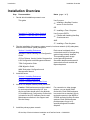
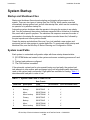
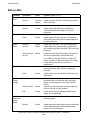
Installation Overview
Step
1.
Documentation
Notes (page 1 of 2)
Decide which installation process to use.
This guide
Use if you are:
•
Installing a NonStop S-series
server for the first time
OR
•
Appendix E, FastPath Tasks: Required
Appendix F, FastPath Tasks: Optional
Installing a Tetra 16 system
Use if you are BOTH:
•
Familiar with installing NonStop
S-series servers
AND
•
2.
Installing a Tetra 8 system
Plan the installation of the server, system console, local area network (LAN) subsystem,
and wide area network (WAN) subsystem.
Section 2, Installing Enclosures
NonStop S-Series Planning and Configuration
Guide
G06.nn Release Version Update Compendium
LAN Configuration and Management Manual
TSM Configuration Guide
Each server is shipped with a
customized version of the operating
system image already installed.
This operating system image
comes preconfigured with
ServerNet adapters and essential
system devices such as disk and
tape subsystems.
OSM Migration Guide
WAN Subsystem Configuration and
Management Manual
3.
Install the server.
Section 2, Installing Enclosures
Section 3, Cabling Enclosures
Section 4, Installing Service-Side Doors
4.
Install an I/O adapter module (IOAM) enclosure.
Caution: IOAM enclosures must be installed
by service providers trained by HP. Your
service provider should refer to the Modular
I/O Installation and Configuration Guide which
is located in the NTL Hardware Service and
Maintenance collection in the Support and
Service Library.
5.
For connection to other storage
options, you can install IOAM
enclosures. Each IOAM enclosure
is mounted into a standard 19-inch
rack and connects to the MSEB of
S76000 and later NonStop S-series
systems. Each IOAM enclosure
provides space for up to 10
specially designed ServerNet
adapters.
Install the primary system console.
HP NonStop S-Series Hardware Installation and FastPath Guide—541880-001
1 -3
Installation Overview
Introduction
Step
Documentation
Notes (page 1 of 2)
Section 5, Installing, Starting, and Testing a
System Console
The primary system console has a
modem and is configured as a dialout point. You must install and
configure this system console
before you can view manuals, start
and test the system, configure the
OSM or TSM environment, or use
the OSM or TSM software.
Section 6, Connecting a System Console
Do not install the backup system
console until you have started and
tested the server.
6.
Install external system devices such as 517x and 519x tape subsystems:
Section 7, Installing External System Devices
7.
Power on and start the server with the factory-default configuration.
Section 8, Powering On and Starting the
System
8.
Perform post-startup tasks such as testing system components and configuring the
OSM or TSM environment.
Section 9, Performing Post-Startup Tasks
You might also need:
•
•
•
•
SCF Reference Manual for the
Storage Subsystem
OSM User’s Guide
TSM Configuration Guide
TSM Online User Guide
HP NonStop S-Series Hardware Installation and FastPath Guide—541880-001
1 -4
Installation Overview
Introduction
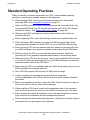
Standard Operating Practices
When you handle a customer-replaceable unit (CRU), follow standard operating
practices to minimize any potential damage to the equipment:
•
•
•
•
•
•
•
•
•
•
•
•
•
•
•
When handling CRUs, work in an environment protected from electrostatic
discharge (ESD). See Using ESD Protection on page 1-6.
Obtain an ESD protection kit and follow the directions that come with the kit. You
can purchase ESD kits from HP using the part number given in the NTL Support
and Service Library. See Support and Service Library on page xxiv.
Make sure any ESD wriststrap has a built-in series resistor and includes an
antistatic table mat.
Before unpacking CRUs, place the packing container on an antistatic table mat.
CRUs that require ESD protection are shipped in ESD protective bags. When
opening packing containers for these CRUs, do not cut the ESD protective bag.
Before moving a CRU from an antistatic table mat, attach the grounding clip from
your ESD wriststrap to any exposed unpainted metal surface on the CRU frame.
Before you bring the CRU in contact with the system enclosure, attach the
grounding clip to any exposed unpainted metal surface on the enclosure frame.
When removing a CRU from an enclosure, once you have pulled the CRU partway
out of the slot, attach the grounding clip from your ESD wriststrap to any exposed
unpainted metal surface on the CRU frame.
Before setting a CRU on an antistatic table mat, attach the grounding clip from your
ESD wriststrap to the antistatic table mat.
Store CRUs that require ESD protection in ESD protective bags.
Install or upgrade only hardware components that are designated
customer-replaceable units (CRUs) and for which this guide includes installation
procedures.
Before any installation procedure, inspect the CRU. Check connectors for bent or
broken pins and look for any other obvious damage.
When installing a CRU that is located on the appearance side of the enclosure,
work quickly to minimize the amount of time that the enclosure door is left open.
Before working with electrical equipment, remove all metal accessories, such as
rings, watches, and necklaces, that can damage the equipment.
Before working with electromechanical equipment, restrain items such as long hair
and sleeves that can get caught in the equipment.
HP NonStop S-Series Hardware Installation and FastPath Guide—541880-001
1 -5
Installation Overview
Introduction
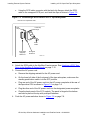
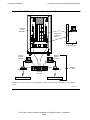
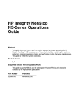
Using ESD Protection
System Enclosure (Appearance Side)
ESD wriststrap clipped to door latch stud
ESD floor mat
ESD floor mat
ESD antistatic table mat.
Connect to soft ground
(1 megohm min to 10
megohm max)
Clip 15-foot straight
ground cord to screw on
grounded outlet cover.
VST693.vsd
HP NonStop S-Series Hardware Installation and FastPath Guide—541880-001
1 -6
Installation Overview
Introduction
Tools
The tools you might need when installing server components include:
Component
Tool
Purpose
System
enclosure
ESD protection kit
Protect components against electrostatic
discharge
Heavy-freight-handling
equipment
Move shipping pallets to installation area
Safety glasses
Prevent eye injury from flying particles
Scissors or cutters
Clip cable ties and cut banding straps
Flashlight
For lighting dark areas
Labels
Pens or pencils
Label cables
3/4-inch (19-mm) or
9/16-inch (15-mm)
open-end wrench
Lower system enclosure leveling pads (might
have 3/4-inch nuts or 9/16-inch nuts)
Phillips screwdriver
Loosen and tighten Phillips screws, including
groundstrap screws
Stubby Phillips
screwdriver
Loosen and tighten AC power cord retainer
screws on some processor and I/O enclosures
without power shelves
4-mm diagonal wrench
(provided with server)
Unlock enclosure door
15/16-inch (24-mm) or
adjustable, open-end
wrench
Lower leveling pads on 5175 or 519x tape
subsystem enclosures
Slotted screwdriver
Loosen and tighten slotted-head screws,
including those on 5175 tape subsystem
shipping restraints
Tape
subsystem
HP NonStop S-Series Hardware Installation and FastPath Guide—541880-001
1 -7
Installation Overview
Introduction
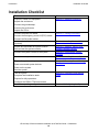
Installation Checklist
Task
Prepare to install new equipment.
See...
Section 2, Installing Enclosures
Unpack the enclosures.
Connect the groundstraps.
Inventory the enclosures.
Inspect the CRUs.
Connect the power-on cables.
Section 3, Cabling Enclosures
Connect the emergency power-off (EPO) cables.
Connect the ServerNet cables.
Install service-side doors on system enclosures
(optional).
Unpack and assemble the system console.
Start and test the system console.
Connect the system console to the system.
Install external system devices.
Prepare for system startup.
Power on external system devices.
Section 4, Installing Service-Side
Doors
Section 5, Installing, Starting, and
Testing a System Console
Section 6, Connecting a System
Console
Section 7, Installing External System
Devices
Section 8, Powering On and Starting
the System
Power on the system.
Start the system.
Test the system.
Complete final installation tasks.
Section 9, Performing Post-Startup
Tasks
Prepare for daily operations.
Configure the OSM or TSM environment.
Create the operating configuration.
Section 10, Configuring the System
HP NonStop S-Series Hardware Installation and FastPath Guide—541880-001
1 -8
Installation Overview
Introduction
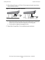
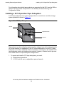
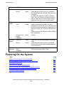
Shipping Packages
Each enclosure or stack of enclosures is shipped in a shipping package.
Note. For information about shipping packages for IOAM enclosures, including package
specifications and unpacking instructions, contact your HP trained service provider who can
refer to the Modular I/O Installation and Configuration Guide located in the NTL Hardware
Service and Maintenance Collection in the Support and Service Library.
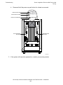
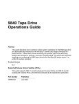
About Shipping Packages
The shipping package consists of protective cardboard panels on the top and sides of
the enclosure, secured with nylon banding straps that are 1.5 inches (3.75 mm) wide.
Equipment is included in your shipment so that you can unload the shipping packages
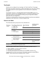
as follows:
•
Wooden pallets
Each shipping package comes equipped with a wooden pallet as shown in
Figure 1-1, The Shipping Package. This pallet includes skids spaced for forklift
handling.
•
The unloading ramp
°
°
The ramp allows you to unload the enclosure from the pallet without a forklift.
°
The ramp is attached to one shipping package with banding straps as shown in
Figure 1-1, The Shipping Package.
Only one unloading ramp is included in the shipment, regardless of the number
of enclosures shipped.
HP NonStop S-Series Hardware Installation and FastPath Guide—541880-001
1 -9
Installation Overview
Introduction
Figure 1-1. The Shipping Package
Banding Straps
Unloading Ramp
Pallet
Single-High Stack
Double-High Stack
VST963.vsd
Shipping Package Specifications
Table 1-1. Weights for Enclosure Shipping Packages
NonStop S-Series Enclosure Type
Single-High Stack
Double-High Stack
Pounds
Kilograms
Pounds
Kilograms
S7000 processor enclosure without power
shelf
290
132
580
264
S7x00 and Sxx000 processor enclosure
with power shelf
367
167
734
337
I/O enclosure without power shelf
290
132
580
264
I/O enclosure with power shelf
367
167
734
334
Note. For information about shipping package specifications for IOAM enclosures, contact
your HP trained service provider who can refer to the Modular I/O Installation and
Configuration Guide located in the NTL Hardware Service and Maintenance Collection in the
Support and Service Library.
HP NonStop S-Series Hardware Installation and FastPath Guide—541880-001
1-10
Installation Overview
Introduction
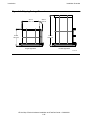
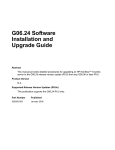
Figure 1-2. Shipping Package Dimensions
41.6 in
105.7 cm
43.0 in
109.2 cm
28.8 in
73.0 cm
77.0 in
195.6 cm
Single-High Stack
Double-High Stack
VST990.vsd
HP NonStop S-Series Hardware Installation and FastPath Guide—541880-001
1-11
Installation Overview
Introduction
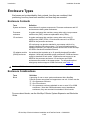
Enclosure Types
Enclosures can be described by their contents, how they are combined, their
positioning, how they have been modified, and how they are mounted.
Enclosure Contents
Term
Definition
System enclosure
An enclosure for system components. Processor enclosures and I/O
enclosures are both system enclosures.
Processor
enclosure
A system enclosure that contains, among other units, two processor
multifunction (PMF) customer-replaceable units (CRUs).
I/O enclosure
A system enclosure that contains, among other units, two I/O
multifunction (IOMF) CRUs. I/O enclosures connect to a SEB or
MSEB in the processor enclosure.
I/O enclosures can also be attached to a processor switch of an
Integrity NonStop NS-series system. For more information and for
cabling procedures, your service provider should refer to the NonStop
NS-Series Hardware Installation Manual.
I/O adapter module
(IOAM) enclosure
An enclosure that contains up to 10 specially designed ServerNet
adapters. Unlike self-contained system enclosures, IOAM enclosures
reside in standard 19-inch racks. IOAM enclosures connect to an
MSEB in the processor enclosure. I/O enclosures and IOAM
enclosures can coexist in the same system. For information about
what group numbers support IOAM enclosures, see Table 1-2.
Caution. IOAM enclosures must be installed by service providers trained by HP.
Enclosure Combinations
Term
Definition
Block
A grouping of one or more system enclosures that a NonStop
S-series system recognizes and supports as one unit. A block can be:
One processor enclosure
One I/O enclosure
One processor enclosure attached to one or more I/O or IOAM
enclosures. Note that IOAM enclosures are not standalone
enclosures; they are mounted into standard 19-inch racks.
•
•
•
For more about blocks, see the NonStop S-Series System Expansion and Reduction
Guide.
HP NonStop S-Series Hardware Installation and FastPath Guide—541880-001
1-12
Installation Overview
Introduction
Enclosure Positions
System enclosures can be arranged in single-high stacks (one enclosure) or
double-high stacks (two enclosures, one on top of the other):
Term
Definition
Base enclosure
A system enclosure that can be placed on the floor with another
enclosure on top of it.
Stackable enclosure
A system enclosure that can rest on top of another system
enclosure.
If you will reduce your system at any point in the future, place enclosures that you
might remove from your system on the top of the stack.
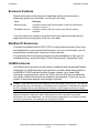
Modified I/O Enclosures
I/O enclosures shipped with the G06.13 RVU or earlier require removal of a pin from
their backplanes to ensure system fault tolerance. If you do not know when your I/O
enclosure was manufactured, contact your service provider.
For information about the removal procedure and the possibilities for later use of a
modified enclosure, see the NonStop S-Series Planning and Configuration Guide.
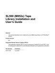
IOAM Enclosures
An IOAM enclosure provides you with access to additional disk storage and Ethernet
connectivity. An IOAM enclosure is mounted into a modular cabinet and connects to
the MSEB of S76000 and later NonStop S-series systems. Up to three IOAM
enclosures, one maintenance switch, two PDUs, and one UPS can be installed into
one cabinet. IOAM enclosures can be installed in any standard 19-inch rack, but the
number of enclosures depends on the height of the rack.
Caution. IOAM enclosures must be installed by service providers trained by HP. Your service
provider should refer to the Modular I/O Installation and Configuration Guide which is located in
the NTL Hardware Service and Maintenance Collection in the Support and Service Library.
Note. Ensure that the correct firmware is installed on the processor and IOAM enclosures.
Minimum firmware is required to allow IOAM enclosures to be connected to processor
enclosures in the outer tetrahedron. For correct firmware requirements, your service provider
can refer to the Modular I/O Installation and Configuration Guide.
HP NonStop S-Series Hardware Installation and FastPath Guide—541880-001
1-13
Installation Overview
Introduction
IOAM Enclosure Components
An IOAM enclosure (chassis) contains two midplanes:
•
•
I/O midplane for routing ServerNet signals
Power midplane for routing power and signals for the power-supply controls
These components are installed in an IOAM enclosure:
•
•
Two ServerNet switch boards for routing ServerNet packages from the MSEB to
the ServerNet adapters. The ServerNet switch board enables communication
between a NonStop S-series system and an IOAM.
Up to 10 ServerNet adapters. These adapters include:
°
Fibre Channel ServerNet adapters (FCSA). FCSAs provide access to:
•
•
°
•
•
•
•
Fibre Channel storage devices, such as the Fibre Channel disk module
(FCDM)
Enterprise Storage System (ESS).
Gigabit Ethernet 4-port ServerNet adapters (G4SA). G4SAs provide increased
Ethernet capacity. An IOAM enclosure that has 10 G4SAs provides up to 40
ports of Ethernet connections.
Four fans for cooling components inside an IOAM enclosure
Four power supplies with universal AC input to provide power to the components in
an IOAM enclosure
One bezel
Two cable-management systems for managing the fiber-optic cables at the module
level and at the modular cabinet level when it is installed on the modular cabinet
Note. For FCSA information, your service provider can refer to the Fibre Channel
ServerNet Adapter (FCSA) Installation and Support Guide.
For G4SA information, your service provider can refer to the Gigabit Ethernet 4-Port
Adapter Installation and Support Guide.
For FCDM or ESS information, refer to the NonStop S-Series Planning and Configuration
Guide or your service provider can refer to the Modular I/O Installation and Configuration
Guide.
Related Components
These components are used in conjunction with IOAM enclosures:
•
Maintenance switch
The maintenance switch connects the OSM console to the Maintenance Entity in
the ServerNet switch board and provides the communication between the IOAM
HP NonStop S-Series Hardware Installation and FastPath Guide—541880-001
1-14
Installation Overview
Introduction
enclosure and the OSM console. The maintenance switch can be mounted in a
standard 19-inch rack.
•
Modular cabinet
A modular cabinet is a 19”, 42 U high, industry standard rack and is used for
mounting modular components. It houses the IOAM enclosure, uninterruptible
power supplies (UPS), Extended Run-Time Modules, and maintenance switches.
The modular cabinet comes equipped with doors, power distribution units (PDUs),
and side panels as needed.
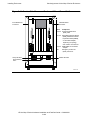
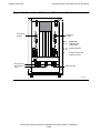
•
Power distribution unit (PDU)
The PDU supports additional power outlets for the components in the rack. The
PDU is installed onto a rack extender frame attached to the modular cabinet. See
Figure 1-9. For an IOAM enclosure, each IOAM power supply plugs into a different
PDU.
•
Uninterruptible power supply (UPS)
For IOAM enclosures, a UPS is optional but recommended where a site UPS is not
available. You can choose to use any UPS that meets the IOAM enclosure power
requirements for all enclosures being powered on from the UPS. One UPS option
to support the IOAM enclosure is the HP R5500 UPS. You can also choose to have
the UPS pre-installed inside the Modular Cabinet. See Figure 1-9.
The standard configuration for cabinets that have an R5500 XR UPS includes one
Extended Runtime Module (ERM). Each Extended Runtime Module is a rackmountable battery module that extends your overall battery runtime.
For power and environmental requirements for the R5500 UPS, and all planning,
installation, and emergency power-off (EPO) instructions, refer to the
documentation shipped with the UPS.
HP NonStop S-Series Hardware Installation and FastPath Guide—541880-001
1-15
Installation Overview
Introduction
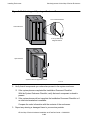
Enclosure Illustrations
Figure 1-3. Base and Stackable Enclosures
Base Enclosure
(Appearance Side)
Stackable Enclosure Installed
on Base Enclosure
(Appearance Side)
VST547.vsd
WARNING. Do not attempt to lift a stackable enclosure onto the top of a base enclosure by
yourself. A trained service provider and at least four assistants must perform this procedure.
HP NonStop S-Series Hardware Installation and FastPath Guide—541880-001
1-16
Installation Overview
Introduction
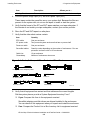
Figure 1-4. SEBs in a Processor Enclosure Without a Power Shelf
55
50
51 52 53 54
X-Fabric SEB
Y-Fabric SEB
56
VST581.vsd
HP NonStop S-Series Hardware Installation and FastPath Guide—541880-001
1-17
Installation Overview
Introduction
.
Figure 1-5. MSEBs in a Processor Enclosure With a Power Shelf
50
55
51 52 53 54
X-Fabric MSEB
Y-Fabric MSEB
56
VST969.vsd
HP NonStop S-Series Hardware Installation and FastPath Guide—541880-001
1-18
Installation Overview
Introduction
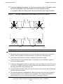
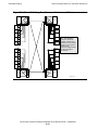
Figure 1-6. Service Side of I/O Enclosure Without Power Shelf
Slot
50, 55
51, 52, 53, 54
56
Component
IOMF CRU
SEB or MSEB
EPO connector
50
55
51 52 53 54
To X Fabric
To Y Fabric
56
VST970.vsd
HP NonStop S-Series Hardware Installation and FastPath Guide—541880-001
1-19
Installation Overview
Introduction
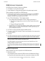
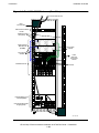
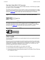
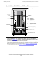
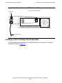
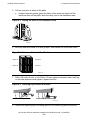
Figure 1-7 illustrates the service side of an I/O enclosure that has a power shelf. The
power shelf has two DC power supplies that furnish power to the IOMF 2 CRUs in slots
50 and 55.
The IOMF 2 CRU offers more connectivity options than the IOMF CRU. On the IOMF 2
CRU, the external SCSI port accepts the SCSI SAC used on PMF 2 and
ServerNet/DAs for connecting tape devices. The ServerNet port accepts serial-copper
and single-mode fiber-optic cables in addition to ECL cables.
Figure 1-7. Service Side of I/O Enclosure With Power Shelf
Slot
50, 55
51, 52, 53, 54
56
Component
IOMF 2 CRU
SEB or MSEB
EPO connector
55
55
50
50
51 52 53 54
To X Fabric
To Y Fabric
SCSI Port
DC Power Cable (1 of 2)
56
Power Shelf
VST972.vsd
HP NonStop S-Series Hardware Installation and FastPath Guide—541880-001
1- 20
Installation Overview
Introduction
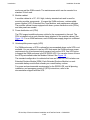
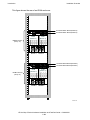
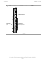
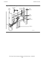
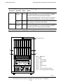
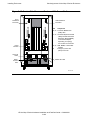
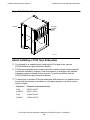
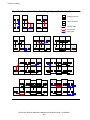
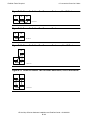
Figure 1-8. Rack with IOAM Enclosure (Front Side)
42
42
41
41
40
40
39
39
38
37
37
36
36
35
35
34
34
33
33
32
32
31
31
30
30
29
29
28
IOAM Enclosure
38
Disk Driv e Slots 1-14
Disk Driv e Slots 1-14
Fi bre Channel Disk
Module (FCDM)s
28
27
27
26
26
25
25
24
24
23
23
22
22
21
21
20
20
19
19
18
18
17
17
16
16
15
15
14
14
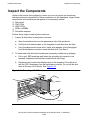
13
13
12
12
11
11
10
10
09
09
08
08
07
07
06
06
05
05
04
04
03
03
02
02
01
01
Fans
Power Supplies
Extended Run-Ti me Module (ERM)
Uninterruptible Power Supply (UPS)
VST 010.vsd
HP NonStop S-Series Hardware Installation and FastPath Guide—541880-001
1- 21
Installation Overview
Introduction
Figure 1-9. Rack With IOAM Enclosure (Rear Side)
To AC Power Source
42
PDU
Junction Box
41
40
39
Maintenance Switch
Power
Distribution
Unit (PDU)
38
42
41
40
37
39
36
35
34
38
37
36
33
35
32
34
Fibre Channel
Disk Module
(FCDM)s
31
30
29
33
32
31
Fibre Optic
Cables
28
Fi bre Optic
Cables
30
27
29
26
25
24
23
IOAM Enclosure
22
21
20
28
27
26
Fibre
Channel
Connection
to ESS
25
24
FCSAs
23
22
19
21
18
17
16
20
19
18
15
17
14
16
13
12
11
15
14
13
10
12
09
11
08
07
Extended Run-Time
Module (ERM)
06
10
09
08
05
07
04
06
Uninterruptible Power
Supply (UPS)
03
02
01
05
04
03
02
01
VST 197.vsd
HP NonStop S-Series Hardware Installation and FastPath Guide—541880-001
1- 22
Installation Overview
Introduction
Groundstraps
What Groundstraps Do
Groundstraps:
•
•
Maintain the ground potential between NonStop S-series system enclosures
Protect the system from harmful electrical transients
Note. For grounding information for IOAM enclosures, your service provider can refer to
the Modular I/O Installation and Configuration Guide located in the NTL Hardware Service
and Maintenance Collection in the Support and Service Library.
Number of Groundstraps
For any system, the number of groundstraps required is equal to the number of
NonStop S-series enclosures minus one. For example, if a system contains six
enclosures, five groundstraps are required.
Where to Install Groundstraps
Groundstraps are installed between two enclosures, either in a stack or between
adjacent stacks. Groundstraps are not required between separate rows. For examples
of groundstrap locations for a variety of enclosure arrangements, see Figure 2-11 on
page 2-14 and Figure 2-12 on page 2-15.
A groundstrap connecting two system enclosures in a double-high stack might be
installed at the factory on a new system or an add-on enclosure. However, if you have
three or more enclosures, you must install the groundstraps that link the base
enclosures.
More About Groundstraps and Power Requirements
•
•
Groundstraps are installed on systems that have more than one enclosure.
Groundstraps are 14.8 inches (37.5 centimeters) long.
HP NonStop S-Series Hardware Installation and FastPath Guide—541880-001
1- 23
Installation Overview
Introduction
Power-On Cables
For Information About
See
When to use specific cable lengths
NonStop S-Series Planning and Configuration Guide
Where to install the power-on cables
•
•
Your Installation Document Checklist
Appendix C, Power-On Cabling
Power-on cables carry the power-on signal from one PMF CRU or IOMF CRU to
another, allowing you to power on all system enclosures in a system from one push
button.
Note. IOAM enclosures do not require power-on cables. For more information, your service
provider can refer to the Modular I/O Installation and Configuration Guide located in the NTL
Hardware Service and Maintenance Collection in the Support and Service Library.
•
•
•
•
Power-on cables have an RJ-11 connector at each end as illustrated in
Figure 1-10.
One power-on cable is required for each system enclosure.
Power-on cables can be 8.2 feet (2.5 meters) or 23.0 feet (7.0 meters) long.
The cables and enclosures must form a continuous ring so that each enclosure
can deliver the power-on signal to the next enclosure.
Figure 1-10. Power-On Cable Connectors
System Enclosure
(Service Side)
Power-On Cable
VST703.vsd
HP NonStop S-Series Hardware Installation and FastPath Guide—541880-001
1- 24
Installation Overview
Introduction
Emergency Power-Off Cables
Emergency power-off (EPO) cables automatically disconnect electrical power to
connected equipment if an electrical emergency occurs.
Note. For EPO information for IOAM enclosures, contact your service provider who can refer
to the Modular I/O Installation and Configuration Guide located in the NTL Hardware Service
and Maintenance Collection in the Support and Service Library.
About EPO Cables
Figure 1-11. EPO Cable
Unterminated End
VST980.vsd
•
•
•
•
EPO cables usually connect to a junction box of the computer room EPO system.
(The EPO system must provide contact closure during an emergency.)
One EPO cable for each enclosure is shipped with your system.
The EPO cable is equipped with a two-pin Mate-N-Lock style plug at one end. This
plug attaches to the EPO connector socket in slot 56.
The other end of the EPO cable is unterminated, to attach to the EPO system.
EPO Cable Requirements
Within the United States
An EPO disconnect is required in a system if the system is installed in a computer or
data processing room that is designed to comply with the construction and
fire-protection provisions of:
•
•
NFPA-75, Protection of Electronic Computer/Data Processor Equipment
Article 645 of NFPA-70, the National Electric Code
Outside the United States
EPO disconnects are usually not required unless specified by local authorities.
If a System Requires EPO Capability
If a system requires EPO capability, the customer is responsible for connecting an
EPO cable to the EPO connector in slot 56 on the service side of all system
enclosures.
HP NonStop S-Series Hardware Installation and FastPath Guide—541880-001
1- 25
Installation Overview
Introduction
If a System Does Not Require EPO Capability
If a system does not require EPO capability, go to ServerNet Cabling on page 1-35.
System Organization
This subsection describes the organization, group numbering, and labeling in a
NonStop S-series system. For IOAM enclosure organization, see Group, Module, and
Slot Hierarchy for IOAM Enclosures on page 1-28.
A system consists of the hardware and the software that runs on it. To perform
hardware operations using the OSM or TSM package, you must be familiar with the
organization and naming conventions and know how to identify individual components
within the server.
OSM has a naming convention similar to, but more abbreviated than, the naming
convention for system resource locations in TSM. For example, TSM displays the
location of a fan CRU in this form:
FAN.GRP-1.MOD-1.SLOT-26
OSM displays the location of the same fan CRU in this form:
FAN (1.1.26)
Group, Module, and Slot Hierarchy for System Enclosures
Hardware in a server is organized according to a system, group, module, and slot
hierarchy, as follows:
Term
Definition
System
A set of groups and external hardware components.
Group
A set of components accessible to a pair of service processors (SPs) in a system
enclosure. In a NonStop S-series server, an enclosure contains one group.
Module
A set of slots sharing a common hardware interconnect (such as a backplane).
Slot
A labeled physical space in an enclosure in which a component can be installed.
A system enclosure can be serviced from two sides:
Term
Definition
Appearance
side
Contains fans, disk customer-replaceable units (CRUs), group ID switches,
and power monitor and control unit (PMCU) CRUs.
Service
side
Provides access to the PMF CRUs or IOMF CRUs as well as to the
ServerNet expansion boards (SEBs), modular SEBs (MSEBs), and ServerNet
adapters. Cables are also accessed from the service side.
HP NonStop S-Series Hardware Installation and FastPath Guide—541880-001
1- 26
Installation Overview
Introduction
Group, Module, and Slot Hierarchy Illustration
This figure illustrates the service side and the appearance side of a processor
enclosure:
Appearance Side
Service Side
50
Group
55
01 02 03 04 05 06 07 08
Module
51 52 53 54
11 12 13 14 15 16 17 18
09
19
10
20
21
22
23
28
24
25
26
56
Slots
27
29
30
31
32
VST721.vsd
HP NonStop S-Series Hardware Installation and FastPath Guide—541880-001
1- 27
Installation Overview
Introduction
Group, Module, and Slot Hierarchy for IOAM Enclosures
Hardware in an IOAM enclosure is organized according to a group, module, and slot
hierarchy:
Term
Definition
Group
The IOAM enclosure and all the components within it. IOAM
enclosures are numbered in the same way as I/O enclosures.
Module
One I/O adapter module (IOAM). There are two IOAMs in an
IOAM enclosure, numbered 2 and 3. Each IOAM contains:
•
•
•
•
Slot
One ServerNet switch board connected to a fabric. The
ServerNet switch board in module 2 is connected to the X
fabric, and the ServerNet switch board in module 3 is
connected to the Y fabric.
Two power supplies
Two fans
Up to five ServerNet adapters
A physical space in the IOAM module in which a component
can be installed. Slot numbers are assigned for each module:
Slot Number
Component
1, 2, 3, 4, 5
ServerNet adapter
14
ServerNet switch board
15 and 18
Power supplies
16 and 17
Fans
To perform hardware operations on an IOAM enclosure, you must use OSM. TSM
does not support IOAM enclosures. To identify individual components within the IOAM
enclosure using OSM, you must be familiar with the organization and naming
conventions. For example, OSM displays the location of a fan in group 11, module 3,
slot 17 in this form:
Fan(11.3.17)
HP NonStop S-Series Hardware Installation and FastPath Guide—541880-001
1- 28
Installation Overview
Introduction
Group, Module, and Slot Hierarchy Illustrations of an IOAM
Enclosure
This figure shows the front of an IOAM enclosure:
42
42
41
41
40
40
39
39
38
38
37
36
37
Fans
(Module 3)
35
Fans
(Module 2)
34
IOAM Enclosure
(Group 12)
33
Slot 17
Slot 17
32
31
31
30
30
29
28
29
Slot 16
Slot 16
27
25
28
27
26
26
Power Supplies
Modules 2 and 3
25
24
24
23
23
22
22
21
21
20
20
19
Fans
(Module 3)
Fans
(Module 2)
19
18
18
17
17
16
15
IOAM Enclosure
(Group 11)
35
34
33
32
36
16
Slot 17
Slot 17
15
14
14
13
13
12
11
12
Slot 16
Slot 16
10
10
09
08
07
11
09
Power Supplies
Modules 2 and 3
08
07
06
06
05
05
04
04
03
03
02
02
01
01
VST052.vsd
HP NonStop S-Series Hardware Installation and FastPath Guide—541880-001
1- 29
Installation Overview
Introduction
This figure shows the rear of an IOAM enclosure:
42
42
41
41
40
40
39
39
38
38
37
37
36
36
35
35
34
34
ServerNet Switch Board (Module 2)
33
33
ServerNet Switch Board (Module 3)
32
32
31
30
Slot 5
Slot 4
Slot 3
Slot 2
Slot 5
Slot 1
Slot 4
27
29
Slot 3
28
Slot 2
29
Slot 1
IOAM Enclosure
(Group 12)
31
IOAM
(Module 3)
IOAM
(Module 2)
30
27
26
26
25
25
24
24
23
23
Module 2
22
Module 3
22
21
21
20
20
19
19
18
18
17
17
ServerNet Switch Board (Module 2)
16
16
ServerNet Switch Board (Module 3)
15
15
14
IOAM
(Module 3)
IOAM
(Module 2)
13
Slot 5
Slot 4
Slot 3
Slot 2
Slot 5
Slot 1
Slot 4
10
14
13
12
Slot 3
11
Slot 2
12
Slot 1
IOAM Enclosure
(Group 11)
28
11
10
09
09
08
08
07
07
06
05
06
Module 2
Module 3
05
04
04
03
03
02
02
01
01
VST050.vsd
HP NonStop S-Series Hardware Installation and FastPath Guide—541880-001
1- 30
Installation Overview
Introduction
Server Numbering and Labeling
For Information About
Processor and I/O
enclosure connections
Processor and IOAM
enclosure connections
See
•
•
•
NonStop S-Series Planning and Configuration Guide
Section 3, Cabling Enclosures
Your service provider, who can refer to the Modular I/O
Installation and Configuration Guide located in the NTL
Hardware Service and Maintenance Collection in the
Support and Service Library
A NonStop server can contain up to 44 system enclosures (8 processor enclosures
and 36 I/O enclosures) with a total of 16 processors. IOAM enclosures can replace any
or all I/O enclosures.
The type of NonStop server, the configuration, and the RVU all affect the number of I/O
or IOAM enclosures supported. Table 1-2 shows the processors that reside in each
processor enclosure, plus the maximum number of I/O enclosures or IOAM enclosures
that each processor enclosure connects to. Groups 11 through 89 are I/O or IOAM
enclosures.
Note. Ensure that the correct firmware is installed on the processor and IOAM enclosures.
Minimum firmware is required to allow IOAM enclosures to be connected to processor
enclosures in the outer tetrahedron. For correct firmware requirements, your service provider
can refer to the Modular I/O Installation and Configuration Guide.
Table 1-2. Maximum Processor and I/O or IOAM Enclosure Connections
Processor Enclosure
(Group)
Contains Processors
Connects to I/O or IOAM
Enclosures (Groups)
01
0 and 1
11, 12, 13, 14, 15
02
2 and 3
21, 22, 23, 24, 25
03
4 and 5
31, 32, 33, 34, 35
04
6 and 7
41, 42, 43, 44, 45
05
8 and 9
51, 52, 53, 54
06
10 and 11
61, 62, 63, 64
07
12 and 13
71, 72, 73, 74
08
14 and 15
81, 82, 83, 84
HP NonStop S-Series Hardware Installation and FastPath Guide—541880-001
1- 31
Installation Overview
Introduction
Group ID Switches
Set group identification with the two-digit ID switches, located on the inside of system
enclosures near the fans. Each enclosure has two sets of switches. Both the switches
must display the same value. The service processors (SPs) read the switches at power
on. This figure shows the group ID switches:
Group ID
Switch
Group ID
Switch
0
1
VST603.vsd
HP NonStop S-Series Hardware Installation and FastPath Guide—541880-001
1- 32
Installation Overview
Introduction
Identification Labels
Label
Location
Notes
Group
ID
Placed in holders on service and
appearance sides of enclosure
before shipping
These labels help you find CRUs that need
service.
Module
ID
Service and appearance sides of
enclosure
Because there is only one module in each
group, this number is always 01.
Slot
Attached to frame below each
slot
These labels help you find CRUs that need
service.
The numbers shown by the group ID label
and group ID switches must match.
Identification labels on the appearance side of an enclosure
Group 02, Module 01, Slot 03
02
MODULE
01
01
SLOT
03
01
02
03
04
05
06
VST602.vsd
HP NonStop S-Series Hardware Installation and FastPath Guide—541880-001
1- 33
Installation Overview
Introduction
IOAM Enclosure ServerNet Switch Board LCD
Each ServerNet switch board in an IOAM enclosure contains an LCD that reports
information about the enclosure:
Information
Displayed
Description
Example
IP Address
The IP address of the module. Each module
has a separate IP address.
IP: 16.107.134.54
System,
Group, and
Module
The system name, the group number of the
IOAM enclosure, and the module number of
the IOAM.
STAR1-G013-M02
Rack Name
and Offset
Name of the rack and the rack offset of the
IOAM enclosure. The offset is the physical
location of the enclosure within the rack with
offset being the lowest number on the rack
that the enclosure occupies.
Rack: OSM2 -14
The Rack Name and Rack Offset are assigned
using OSM and are also displayed as
enclosure attributes in OSM. Rack Name and
Rack Offset are arbitrary and can be up to
eight characters long.
Using OSM, you can further identify the
location of an IOAM by using the Set Locator
action. You can enter up to 64 characters of
identification text which is displayed in OSM by
the Locator attribute for an IOAM.
Maintenance
Entity
Firmware
The version of the firmware image saved on
the Maintenance Entity of the ServerNet
switch board.
T2805A01_18Jun2004_
13APR2004_SD1-FW
Maintenance
Entity FPGA
The version of the field-programmable gate
array (FPGA) image saved on the
Maintenance Entity of the ServerNet switch
board.
T0437A01_18JUN2004_
25NOV2003AAA-FW
HP NonStop S-Series Hardware Installation and FastPath Guide—541880-001
1- 34
Installation Overview
Introduction
This figure shows the LCD of a ServerNet switch board. Two lines are displayed at a
time. You can use the scroll buttons to move up and down through the display.
ServerNet Switch Board
NEWHP-G013-M02
Rack: OSM2 - 14
LCD
VST053.vsd
ServerNet Cabling
For More Information About
See
Any of this information
NonStop S-Series Planning and Configuration Guide
This subsection describes ServerNet configurations, cables, connections, and routing.
Review this information before connecting ServerNet cables.
System Size
Table 1-3. Maximum Numbers of Enclosures for G06.03 and Later RVUs
NonStop S700
Server
NonStop S7x00 Server
NonStop Sxx000 Server
Tetra 8
1 processor enclosure
2 I/O enclosures
4 processor enclosures
8 I/O enclosures
4 processor enclosures
8 I/O or IOAM enclosures
Tetra 16
N.A.
8 processor enclosures
16 I/O enclosures
8 processor enclosures
36 I/O or IOAM enclosures
Topology
HP NonStop S-Series Hardware Installation and FastPath Guide—541880-001
1- 35
Installation Overview
Introduction
Topologies
Systems can be configured in two topologies, the Tetra 8 and Tetra 16 topologies.
Enclosures are cabled to each other in patterns that depend upon the system topology.
This cabling remains the same regardless of how the enclosures are physically
arranged.
For example, connector 1 on the ServerNet Expansion Board (SEB) in slot 51 of
enclosure 01 connects only to the SEB connector 1 of enclosure 02. Similarly, all I/O
enclosures connect to a unique SEB port although the ports might differ between
Tetra 8 and Tetra 16 configurations.
Therefore, the cabling patterns remain the same whether the enclosures are adjacent,
separated by other enclosures, or located in separate rows.
Fabrics and Slots
The relationships among components, slots, and fabrics are:
Enclosure
System
IOAM
Fits in This Slot
And Connects to
This Fabric
IOMF CRU
IOMF 2 CRU
PMF CRU
50
X
55
Y
SEB
MSEB
Other adapters
51
X
52
Y
53
X
54
Y
IOAM ServerNet switch
board (module 2)
14
X
IOAM ServerNet switch
board (module 3)
14
Y
FCSA or G4SA
1 - 5 (modules 2 and 3)
Connects to both X
and Y fabrics (dualported)
One of These Components
•
•
•
•
•
•
•
•
•
Note. For information about whether SEBs or MSEBs are required for your system, see the
NonStop S-Series Planning and Configuration Guide.
ServerNet cables connect SEBs or MSEBs in a processor enclosure to any of:
•
•
•
SEBs or MSEBs in another processor enclosure
IOMF CRUs in an I/O enclosure
ServerNet switch boards in an IOAM enclosure (MSEB connection only)
In systems with more than one enclosure, all processor enclosures contain SEBs or
MSEBs. These components are installed in slots 51 and 52.
HP NonStop S-Series Hardware Installation and FastPath Guide—541880-001
1- 36
Installation Overview
Introduction
Other components, such as ServerNet/FX adapters and ServerNet/DAs, can be
installed in slots 51 and 52. However, installing components besides SEBs or MSEBs
in these slots prevents the attaching of I/O enclosures to the processor enclosure.
In Tetra 16 topologies, slots 53 and 54 contain SEBs or MSEBs if both the following are
true:
•
•
These slots belong to groups 01 through 04.
I/O enclosures are attached to these groups.
IOAM Enclosure Cabling
An IOAM enclosure is mounted in a standard 19-inch rack and connects to the MSEB
of S76000 and later NonStop S-series systems using multimode LC-SC fiber-optic
cables up to a maximum length of 125 meters. The LC connector connects to the
ServerNet switch board, and the SC connector connects to the MSEB.
Caution. If IOAM enclosures are installed in the field, they must be installed by service
providers trained by HP. All cabling connections, including connections to FCDMs and ESSs,
must be performed by your service provider. Your service provider can refer to the Modular I/O
Installation and Configuration Guide located in the NTL Hardware Service and Maintenance
Collection in the Support and Service Library.
ServerNet Cables
ServerNet cables connect SEBs, MSEBs, IOMF CRUs, IOMF 2 CRUs, and IOAM
enclosures. These connections form the ServerNet system area network (ServerNet
SAN), which allows enclosures and other devices to communicate.
Cable Compatibilities
Different ServerNet cables connect to different components. When more than one type
of cable can connect to a component, the choice of cable depends on the type of plugin card (PIC) connector installed on the component.
HP NonStop S-Series Hardware Installation and FastPath Guide—541880-001
1- 37
Installation Overview
Introduction
Table 1-4. ServerNet Cable Compatibilities With Components
Cable
ECL
Fiber-Optic
Connects to
Port Number
Port Type
IOMF CRU
N.A.
N.A.
IOMF 2 CRU
(with ECL PIC
installed)
N.A.
N.A.
SEB
1-6
N.A.
MSEB
1-5
Variable
IOMF 2 CRU
N.A.
Variable
ServerNet switch
board (IOAM)
1-4
Fiber-optic
1-5
Variable
6
Node-numbering agent (NNA)
N.A.
Variable
1-5
Variable
7-10
Fixed
MSEB
IOMF 2 CRU
Serial-copper
MSEB
Note. For information about cable compatibilities for an IOAM enclosure, your service provider
can refer to the Modular I/O Installation and Configuration Guide located in the NTL Hardware
Service and Maintenance Collection in the Support and Service Library.
HP NonStop S-Series Hardware Installation and FastPath Guide—541880-001
1- 38
Installation Overview
Introduction
Figure 1-12. Port Numbers and Cable Connections on an MSEB
NNA Fiber-Optic PIC
10
6
9
5
4
ServerNet
Serial Copper
ports
3
ServerNet ECL,
Fiber-Optic, or
Serial Copper PICs
8
2
7
1
VST099.vsd
HP NonStop S-Series Hardware Installation and FastPath Guide—541880-001
1- 39
Installation Overview
Introduction
Types of ServerNet Cables
NonStop S-series systems support three kinds of ServerNet cables: emitter-coupled
logic (ECL), fiber-optic, and serial-copper.
ECL Cables
ECL cables have two types of connectors. These different types of connectors allow
the cables to connect SEBs to SEBs, MSEBs to MSEBs, or SEBs to MSEBs.
SEB-to-SEB ECL cables are terminated at each end by a large 50-pin connector.
Figure 1-13. SEB-to-SEB ECL Cable
VST 984.vsd
The MSEB-to-MSEB ECL is terminated at each end by a small 50-pin connector.
Figure 1-14. MSEB-to-MSEB ECL Cable
VST104.vsd
To connect a SEB to an MSEB, use a SEB-to-MSEB ECL cable.
Figure 1-15. SEB-to-MSEB ECL Cable
MSEB Connector
SEB Connector
VST105.vsd
HP NonStop S-Series Hardware Installation and FastPath Guide—541880-001
1- 40
Installation Overview
Introduction
Serial-Copper Cables
Serial-copper cables are lighter than ECL cables.
Figure 1-16. Serial-Copper Cable
Serial-Copper Cable
VST999.vsd
Caution. You can bend or break two small retainer pins inside the associated PIC receptacle.
When you disconnect a serial-copper cable connector from a serial-copper PIC, fully and firmly
depress the tab on the cable connector before pulling out the cable connector.
Fiber-Optic Cables
The NonStop S-series servers support two types of fiber-optic cables: multimode fiber
(MMF) and single-mode fiber (SMF).
Figure 1-17. Fiber-Optic Cable
VST109.vsd
Which cables you use depends on the fiber-optic plug-in cards (F-PICs) installed in the
ports to which the cables connect.
Do not interchange SMF and MMF cables even though their connectors are similar.
SMF cables operate correctly only with SMF PICs, and MMF cables operate correctly
only with MMF PICs. MMF cables are often orange, and SMF cables are often yellow.
You can distinguish the cables by the part numbers printed on them.
For most systems that use fiber-optic cables, MMF cables are recommended. SMF
cables are used primarily with the ServerNet Cluster product to connect MSEBs to
ServerNet cluster switches. For the ServerNet Cluster application, you must install
NNA PICs in connector 6 of each MSEB you plan to use.
Fiber-optic cables allow enclosures to be placed further apart than ECL or
serial-copper cables.
HP NonStop S-Series Hardware Installation and FastPath Guide—541880-001
1- 41
Installation Overview
Introduction
Fiber-Optic Cables With LC-SC Connectors
For the ServerNet Cluster product and the IOAM enclosures, LC-SC fiber-optic cables
are used to connect to the MSEBs.
The duplex Lucent connectors (LC) are used to connect to the transceivers on a 6780
switch in the ServerNet cluster product and to the ServerNet switch boards in an IOAM
enclosure. Figure 1-18 shows a fiber-optic cable terminated by an LC connector.
Figure 1-18. LC Connector for the 6780 Switch or ServerNet Switch Board
VST107.vsd
The duplex subscriber connector (SC) connects to a port on the MSEB. For the
ServerNet cluster product, you must install NNA PICs in connector 6 of each MSEB
you plan to use. Figure 1-19 shows a fiber-optic cable with an SC connector.
Figure 1-19. SC Connector for MSEB
VST108.vsd
Cable Lengths
The ServerNet cable lengths for your system depend on how your system enclosures
will be arranged.
Although two enclosure arrangements might be logically equivalent, the cable lengths
required might vary greatly: various enclosure arrangements are possible for the same
configuration. Configurations might be laid out in a single row or multiple rows, and
enclosures might be stacked in different combinations.
You can determine cable lengths for your system in two ways:
•
•
See the System Enclosure Arrangement Form for your system.
See the instructions for determining cable length in the NonStop S-Series Planning
and Configuration Guide.
HP NonStop S-Series Hardware Installation and FastPath Guide—541880-001
1- 42
Installation Overview
Introduction
Cable Labels
Label both ends of each cable. Figure 1-20 shows a cable that connects port 5 of an
SEB in slot 51 of the group 01 enclosure to the ServerNet port on the IOMF CRU in
slot 50 of the group 11 enclosure.
For more information about labeling, see the NonStop S-Series Planning and
Configuration Guide.
Figure 1-20. ServerNet Cable Labeling
05
51 50
01 11
B F
SEIOM
SE
IOMB 0 15
F 1 105
15 0
SEB 015105
IOMF 1150
SEB 015105
IOMF 1150
VST823.vsd
Cable Routing
To route ServerNet cables across enclosures:
1. Route them straight down.
2. Secure them to a cable support.
3. Direct them into cable channels.
•
•
•
•
•
Secure a cable to the cable support below the CRU to which the cable connects.
Secure the cable so that if you remove that CRU, you do not disrupt other cables.
Secure cables to the anchors on the cable supports. Secure ServerNet cables to
the outer cable support, and Ethernet or power-on cables to the inner one.
In a double-high stack, use only the base enclosure cable channels.
Guideposts guide cables from a stackable enclosure into the cable channels of a
base enclosure.
Guideposts on base enclosures are not often used, but you can route cables
underneath these guideposts to use up extra cable length.
Caution. Do not pass cables or cords through the handles of CRUs or FRUs. The cables or
cords might become accidentally unplugged during later procedures. See Figure 1-21 for
proper cabling.
HP NonStop S-Series Hardware Installation and FastPath Guide—541880-001
1- 43
Installation Overview
Introduction
Figure 1-21. Cable-Management Hardware
Cable
Channel
ServerNet
Cables
Inner CableTie Anchor
Cable
Channel
01
02
Cable
Support
Cable
Guidepost
Cable Tie
VST966.vsd
HP NonStop S-Series Hardware Installation and FastPath Guide—541880-001
1- 44
Installation Overview
Introduction
The System Console
This subsection describes the system console, and introduces terms and concepts you
must understand to install it.
Topic
Page
System Consoles
1-45
The OSM Product
1-46
Primary and Backup System Consoles
1-47
Primary and Backup System Consoles
1-47
Modems
1-48
Preloaded and Supported Hardware and Software
1-49
Software Connections
1-54
System Consoles
A system console is an HP-approved personal computer used to run maintenance and
diagnostic software for NonStop S-series servers. New system consoles are
preconfigured with the required HP and third-party software. When upgrading to the
latest RVU, software upgrades can be installed from the HP NonStop System Console
Installer CD.
System consoles communicate with NonStop S-series servers over a dedicated
service local area network (LAN) or a secure operations LAN. For more information
about LAN connections, see The Dedicated Service LAN on page 6-2.
Using a system console, you can:
•
•
•
•
•
Monitor operations on servers using the OSM or TSM package
View manuals
Run HP Tandem Advanced Command Language (TACL) sessions using
terminal-emulation software
Install and manage system software using the Distributed Systems
Management/Software Configuration Manager (DSM/SCM)
Make remote requests to and receive responses from a server using remote
operation software
HP NonStop S-Series Hardware Installation and FastPath Guide—541880-001
1- 45
Installation Overview
Introduction
The OSM Product
For the G06.22 RVU, the HP Open System Management (OSM) product replaces TSM
as the system management tool of choice for NonStop S-series systems. While TSM is
still supported, OSM offers a browser-based interface that improves scalability,
performance, and other limitations that exist in TSM. OSM is required for support of
new functionality released at the G06.22 RVU and beyond, such as IOAM or Fibre
Channel disk-drive enclosures.
To access the OSM guided replacement procedures, see OSM Guided Replacement
Procedures on page xxiv.
For more information about OSM, and detailed comparisons of OSM and TSM
functions, see the OSM Migration Guide and the OSM User’s Guide.
The TSM Package
The TSM package is a collection of software products that provide troubleshooting,
maintenance, and service tools. The TSM package consists of TSM server software
and TSM client software.
Note. TSM does not support IOAM or Fibre Channel disk-drive enclosures. OSM should be
used to manage systems that include these components.
TSM server software is the portion of the TSM package that resides on the server.
TSM client software is the portion of the TSM package installed on a system console.
For more information about the TSM package or for information about operating or
configuring TSM software:
•
•
•
•
•
TSM Online User Guide
TSM Configuration Guide
TSM Low-Level Link online help
TSM Notification Director online help
TSM Event Viewer online help
HP NonStop S-Series Hardware Installation and FastPath Guide—541880-001
1- 46
Installation Overview
Introduction
Primary and Backup System Consoles
System consoles equipped with modems and configured as primary or backup dial-out
points are referred to as the primary and backup system consoles, respectively.
A primary or backup system console can receive incident reports from the server and
notify a remote service provider of pending hardware or software problems. At least
one system console (the primary system console) is required for the system. Having a
second (or backup) system console is strongly recommended.
System consoles must be connected to the dedicated service LAN. For more
information about dedicated service LAN connections, see The Dedicated Service LAN
on page 6-2.
A server must be connected through an Ethernet LAN to at least one system console.
Primary system consoles and other system consoles compare as follows:
Primary and Backup System Consoles
•
•
•
Must be connected to the dedicated
service LAN.
Can use all OSM and TSM client
applications, including the Low-Level
Link and Notification Director.
Receive incident reports.
Other System Consoles
•
•
•
Can be connected to the dedicated service
LAN or to a secure operations LAN.
Can use the OSM and TSM Low-Level
Link and Notification Director only if
connected to the dedicated service LAN.
Cannot receive incident reports.
Only two system consoles can be
configured to receive and forward (or
dial out) incident reports for each
system. These primary and backup
dial-out points are referred to as the
primary and backup system consoles
for a particular system.
For information about dial-in and dial-out capabilities of system consoles, see the OSM
Notification Director online help or the TSM Notification Director online help.
HP NonStop S-Series Hardware Installation and FastPath Guide—541880-001
1- 47
Installation Overview
Introduction
Modems
Modems modulate or demodulate digital information so that it can be transmitted or
received over a telephone line. It is recommended that you equip primary and backup
system consoles with modems connected to dedicated phone lines. This allows system
consoles to dial out for remote notification of system problems. Dial in for remote
access by your service provider can also be configured.
Note. Dial-out and dial-in are not available in countries where the provided modem is not
certified. In these countries, you cannot dial out incident reports to, or accept dial-in
communications from, your service provider.
Note. The NonStop system console and OSM Notification Director support using HP Instant
Support Enterprise Edition (IEEE) as a web-based alternative to modem dial-out functionality.
For more information on ISEE:
•
•
See the ISEE for NonStop topic in the Service Information section of the NTL Support and
Service Library to learn about ISEE prerequisites and NonStop-specific details that you will
need before downloading and configuring the ISEE client from the HP Hardware Support
Services Web. Authorized service providers can see ISEE for NonStop- HP Internal on the
NTL employee site.
Contact your HP representative.
Dial-Outs
Dial-out capability lets the OSM or TSM Notification Director notify a remote service
provider of pending hardware and software problems. Either of two system consoles,
defined as the primary and backup dial-out points, can be used for dial-outs. In this
guide, these are the primary and backup system consoles. If your system has only one
system console, it is defined as the primary dial-out point.
While both OSM and TSM software can be installed on your system console, you
should use only one of the Notification Director applications to avoid creating duplicate
incident reports and dial-outs for the same problem.
In a dial-out situation, incident reports are forwarded by the server to the primary
dial-out point. If the primary dial-out point does not respond, the reports are forwarded
to the backup dial-out point. Either dial-out point uses the modem to send these reports
to your service provider. Because your service provider has no access to the server,
dial-outs are completely secure.
Configure dial-out capacity with the OSM or TSM Notification Director. If a LAN
contains multiple servers, the primary and backup system consoles should be
configured to receive incident reports from no more than 10 servers on the LAN.
For information about dial-out situations, see the OSM User’s Guide or the TSM
Configuration Guide.
HP NonStop S-Series Hardware Installation and FastPath Guide—541880-001
1- 48
Installation Overview
Introduction
Dial-Ins
Dial-in capability lets a remote service provider access information about your server to
diagnose hardware or software problems. For dial-in, your service provider uses a
system console to dial in to a workstation on the same LAN as your server. The
workstation uses remote operations software, such as Carbon Copy or Microsoft
Windows NetMeeting, to route requests and responses between your server and your
service provider.
All system consoles provided by HP include the software for dial-in capability. Security
mechanisms are available to ensure that dial-ins do not jeopardize your operational
security. For information about dial-in user names, passwords, configuration, and
security, see the TSM Configuration Guide, the OSM User’s Guide, and the online help
and documentation provided with your remote operations software.
Preloaded and Supported Hardware and Software
Personal computers (PCs) provided for use as system consoles come preloaded with
the hardware and software to run OSM software. Additional software, including TSM
software, HP Systems Insight Manager, and ISEE, is supported and can also be
installed on the system console.
Only PCs provided by HP for this purpose are supported as system consoles.
Caution. To preserve the integrity of applications running on system consoles, do not install
any software applications on your system consoles other than those listed in Table 1-5.
Compromising the software on the system console might leave you unable to communicate
with your server.
Note. System consoles are initially configured by HP manufacturing with OSM enabled and
TSM disabled. This includes disabling the power scrub test and processor alarm functionality in
TSM. If you want to use TSM instead of OSM, follow the instructions described under Fallback
Issues in the OSM Migration Guide.
HP NonStop S-Series Hardware Installation and FastPath Guide—541880-001
1- 49
Installation Overview
Introduction
Table 1-5. Preloaded and Supported HP NonStop System Console Software
Software
Function
For more information
OSM Application suite,
which contains these
OSM components:
Lets you service and maintain the
server.
OSM Migration Guide
•
•
•
OSM Low-Level
Link
Down-system support
OSM Notification
Director
Remote services (dial-in, dial-out)
OSM Console
Tools
Start menu shortcuts and default
home pages for easy access to the
OSM Service Connection and OSM
Event Viewer (browser-based OSM
applications that are not installed on
the system console).
Optional but can be
installed:
Lets you service and maintain the
server.
TSM Low-Level
Link (now replaced
by OSM Low-Level
Link)
OSM User’s Guide
TSM Online User Guide
TSM Configuration Guide
TSM Low-Level Link
online help
TSM Service Application
online help
TSM Service
Application
TSM Notification Director
online help
TSM Notification
Director
TSM Event Viewer online
help
TSM Event Viewer
OutsideView terminal
emulator software
Runs a TACL session.
Online help included with
the software
Distributed Systems
Management/Software
Configuration Manager
(DSM/SCM)
Beginning with the G06.19 RVU,
DSM/SCM client software is no
longer available on the HP NonStop
Server System Console Installer.
You must download DSM/SCM
client software from the SUT.
DSM/SCM User’s Guide
Lets a service provider dial in to and
operate a system console from a
remote site using a modem.
Documentation and online
help included with the
software
Optional but can be
installed:
Carbon Copy
remote operations
software
To install and download
the DSM/SCM client:
G06.nn Software
Installation and Upgrade
Guide
HP NonStop S-Series Hardware Installation and FastPath Guide—541880-001
1- 50
Installation Overview
Introduction
Table 1-5. Preloaded and Supported HP NonStop System Console
Software
Function
For more information
WAN Wizard Pro
A graphical user interface (GUI) that
guides you step-by-step through the
configuration of wide area network
(WAN) and local area network
(LAN) software and hardware.
Access the WAN Wizard
Pro on page F-9
Allows you to diagnose SP
problems
Verifying Topology and
System Components,
Step 9, page 8-16
SP Tool
See applicable online help
in the Help menu
See applicable online help
in the Help menu
Internet Explorer 6.0
Allows you access to the World
Wide Web
Adobe Reader
Lets you open and read documents
created in Adobe Portable
Document Format (PDF)
See applicable online help
in the Help menu
Optional but can be
installed:
Provides hardware-level
management
Contact your HP Support
Representative
A web-based alternative to using a
modem for dial-out of incident
reports.
Contact your HP Support
Representative
HP Systems Insight
Manager
Optional but can be
installed:
HP Instant Support
Enterprise Edition
(ISEE)
HP NonStop S-Series Hardware Installation and FastPath Guide—541880-001
1- 51
Installation Overview
Introduction
Preconfigured IP Addresses
New systems are shipped with preconfigured system IP addresses for system
maintenance that OSM and TSM applications use to communicate with the system.
Note. Many components in the IOAM enclosure need IP addresses. These addresses can be
assigned as static or dynamic. For more information and procedures for assigning IP
addresses, your service provider should refer to the Modular I/O Installation and Configuration
Guide which is located in the NTL Hardware Service and Maintenance Collection in the
Support and Service Library.
Table 1-6. Preconfigured IP Addresses for a NonStop S-Series Server
Component
IP Address
Primary system console
192.231.36.1
Notes
•
•
•
•
MSP0
192.231.36.2
•
•
MSP1
192.231.36.3
•
•
NonStop operating system
access using $ZTCP0
192.231.36.10
•
•
NonStop operating system
access using $ZTCP1
192.231.36.11
•
•
All system consoles provided by HP are
preconfigured with IP address
192.231.36.1.
Two system consoles on the same LAN
cannot use the same IP address.
If the primary system console uses IP
address 192.231.36.1, you must change
the IP address on all other new system
consoles before connecting them to the
LAN.
The recommended IP address for a
backup system console is 192.231.36.4.
Access is through the Ethernet port on
the PMF CRU in group 01, module 01,
slot 50.
This IP address allows you to establish a
low-level link.
Accessed through the Ethernet port on
the PMF CRU in group 01, module 01,
slot 55.
This IP address allows you to establish a
low-level link.
Access is through the Ethernet port on
the PMF CRU in group 01, module 01,
slot 50.
This IP address allows you to establish a
service connection.
Access is through the Ethernet port on
the PMF CRU in group 01, module 01,
slot 55.
This IP address allows you to establish a
service connection.
HP NonStop S-Series Hardware Installation and FastPath Guide—541880-001
1- 52
Installation Overview
Introduction
Table 1-6. Preconfigured IP Addresses for a NonStop S-Series Server (continued)
Component
IP Address
Primary system console
192.231.36.1
Notes
•
•
•
•
MSP0
192.231.36.2
•
•
Subnet
192.231.36.0
Subnet mask
255.255.255.0
Gateway
192.231.36.9
All system consoles provided by HP are
preconfigured with IP address
192.231.36.1.
Two system consoles on the same LAN
cannot use the same IP address.
If the primary system console uses IP
address 192.231.36.1, you must change
the IP address on all other new system
consoles before connecting them to the
LAN.
The recommended IP address for a
backup system console is 192.231.36.4.
Access is through the Ethernet port on
the PMF CRU in group 01, module 01,
slot 50.
This IP address allows you to establish a
low-level link.
MSP IP addresses communicate with the master service processors (MSPs). NonStop
operating system IP addresses communicate with the operating system for the
specified processor. For more information about how these IP addresses are used, see
the NonStop S-Series Planning and Configuration Guide.
To provide security and to make NonStop S-series equipment compatible with your
existing LAN, change these IP addresses before exiting the OSM or TSM Low-Level
Link.
To change the system console, MSP, and operating system access IP addresses, use
the OSM or TSM Low-Level Link. See the documentation appropriate to the software
you are using:
•
•
•
•
OSM Low-Level Link online help
OSM User’s Guide
TSM Low-Level Link online help
TSM Configuration Guide
HP NonStop S-Series Hardware Installation and FastPath Guide—541880-001
1- 53
Installation Overview
Introduction
Software Connections
A system console can communicate with a server using two types of software
connections: a service connection and a low-level link. Both connections support
NonStop user names, but low-level links support up to 18 MSP user names.
A service connection:
•
•
•
•
Is a connection between the OSM or TSM software on a system console and the
OSM or TSM software on the server.
Lets you service and maintain a server when the NonStop operating system is
running.
Gives you comprehensive information about the server. You can examine the state
of all supported devices as seen by the operating system and OSM or TSM server
software.
Is established by the OSM Service Connection or TSM Service Application.
A low-level link:
•
•
•
•
Is a connection between the OSM or TSM software running on a system console
and the master service processors (MSPs) on the server.
Allows communication over a low-level link whether or not the NonStop operating
system is running.
Gives you access to critical information and functions.
Is established by the OSM or TSM Low-Level Link.
HP NonStop S-Series Hardware Installation and FastPath Guide—541880-001
1- 54
Installation Overview
Introduction
System Startup
Startup and Shutdown Files
Startup and shutdown files automate starting and stopping all processes on the
system. There are two types of startup files: the CIIN file, which can be executed
automatically during system load, and all other startup files, which can be invoked by
an operator or by another startup file.
Automating system shutdown aids the operator in bringing the system to an orderly
halt. You can implement the system shutdown sequence with a collection of shutdown
files, each with a specific purpose. The shutdown file sequence reverses the order of
commands in the startup file sequence: applications are shut down first, followed by
the print spooler and other system software.
Create the startup and shutdown files now if you just installed a new system and
previously had no other system to create these files. To create and modify startup and
shutdown files, see the NonStop S-Series Planning and Configuration Guide.
System Load Paths
Each system in a standard configuration ships with these startup characteristics:
•
•
•
$SYSTEM disks are located in the system enclosures containing processors 0 and
1.
System load paths are configured.
The CIIN function is enabled.
If the automatic system load is not successful using one load path, the system load
task attempts to use another path and keeps trying until all possible paths have been
used or the system load is successful. Eight paths are available for loading. Table 1-7
describes each load path in order of use.
Table 1-7. System Load Paths in Order of Use
Data Travels
Load Path
Description
From
To Processor
Over ServerNet Fabric
1
Primary
$SYSTEM-P
0
X
2
Backup
$SYSTEM-P
0
Y
3
Mirror
$SYSTEM-M
0
Y
4
Mirror backup
$SYSTEM-M
0
X
5
Primary
$SYSTEM-P
1
X
6
Backup
$SYSTEM-P
1
Y
7
Mirror
$SYSTEM-M
1
Y
8
Mirror backup
$SYSTEM-M
1
X
HP NonStop S-Series Hardware Installation and FastPath Guide—541880-001
1- 55
Installation Overview
Introduction
The command interpreter input (CIIN) file is automatically invoked after the first
processor is loaded. The CIIN file shipped with new systems contains the TACL
RELOAD * command, which loads the remaining processors.
Figure 1-22 shows possible system load paths.
Figure 1-22. System Load Paths
Processor
0
y
x
Processor
1
y
x
Router
Router
ServerNet
Adapter
ServerNet
Adapter
$SYSTEM-P
ServerNet
Adapter
P
B
MB
M
$SYSTEM-M
ServerNet
Adapter
Legend
= X Fabric
= Y Fabric
VST956.vsd
HP NonStop S-Series Hardware Installation and FastPath Guide—541880-001
1- 56
Installation Overview
Introduction
PMF CRU and IOMF CRU Power-On Self-Tests
When the system is powered on or when a PMF CRU or IOMF CRU is initially
connected to the backplane, a series of automatic power-on self-tests (POSTs) are run
on the CRU. These POSTs take several minutes to finish. The three types of tests are:
•
•
•
CPU memory test (PMF CRU only)
System load path test (PMF CRU only)
Multifunction I/O board (MFIOB) test
At completion of certain self-tests, the service processor (SP) generates events in the
EMS log. Look for the SpEvCruTestComplete event for details about the POST
operations. To view these details, use the OSM or TSM Event Viewer.
Note. For IOAM enclosure, G4SA, and FCSA power-on self-tests, contact your service
provider trained by HP.
CPU Memory Test
The CPU memory test checks the system main memory. If the CPU memory test
finishes successfully, the boot millicode starts the system load path test. If the test fails,
the service processor (SP) lights the amber fault LED on the PMF CRU.
Generally, the CPU memory test fails because of a correctable memory error (CME) or
a hardware error freeze.
To troubleshoot a failed CPU memory test, see Appendix D, Troubleshooting.
System Load Path Test
The system load path test checks the system load paths. If the system load path test
finishes successfully, firmware for the intelligent SCSI processor (ISP) is loaded, the
SCSI buses are scanned, the processor is reset, and the boot millicode starts the
multifunction I/O board (MFIOB) test.
To troubleshoot a failed system load path test, see Appendix D, Troubleshooting.
Multifunction I/O Board (MFIOB) Test
The multifunction I/O board (MFIOB) test checks the MFIOB. If the MFIOB test finishes
successfully, the service processor (SP) extinguishes the amber service LED on the
PMF CRU or IOMF CRU and generates an event, completing the POST. If the MFIOB
test fails, the MFIOB is either partially operational or not operational.
To troubleshoot a failed MFIOB test, see Appendix D, Troubleshooting.
HP NonStop S-Series Hardware Installation and FastPath Guide—541880-001
1- 57
Introduction
Installation Overview
HP NonStop S-Series Hardware Installation and FastPath Guide—541880-001
1- 58
2
Installing Enclosures
This section describes how to unpack new equipment and install NonStop system
enclosures.
Topic
Page
Prepare to Install New Equipment
2-2
1. Review the Documentation
2-2
2. Prepare the Work Space
2-3
3. Organize the Equipment
2-4
Unpack the Enclosures
2-6
Tools
2-6
Unpack the Enclosures
2-6
Connect the Groundstraps
2-13
Inventory the Enclosures
2-16
Slot Assignments for NonStop S-Series Enclosures
Inspect the Components
2-16
2-23
The procedures in this section apply to all types of NonStop S-series processor
enclosures and I/O enclosures.
For information about dimensions, weights, or other specifications of NonStop S-series
enclosures, see Section 1, Introduction.
Notes. If you are adding a processor or I/O enclosure to a previously installed system, see the
NonStop S-Series System Expansion and Reduction Guide.
Caution. A new IOAM enclosure or an additional IOAM enclosure must always be installed by
a service provider trained by HP. Your service provider should refer to the Modular I/O
Installation and Configuration Guide which is located in the NTL Hardware Service and
Maintenance Collection in the Support and Service Library.
HP NonStop S-Series Hardware Installation and FastPath Guide—541880-001
2 -1
Prepare to Install New Equipment
Installing Enclosures
Prepare to Install New Equipment
Complete the steps in this section when your equipment arrives.
1. Review the Documentation
Typically, documentation is provided by the system planner. The system planner gives
you the information you need to perform the installation: what the system configuration
is and the steps to complete.
Has the system planner completed the Installation Document Checklist?
•
If yes:
1. Review all forms, diagrams, and lists in the Installation Document Checklist.
For an example of completed forms, see the NonStop S-Series Planning and
Configuration Guide.
For blank forms, see:
°
°
°
°
°
NonStop S-Series Planning and Configuration Guide
LAN Configuration and Management Manual
SWAN Concentrator Installation and Support Guide
TSM Configuration Guide
ServerNet adapter manuals
2. Ensure that you have everything listed in the checklist.
3. Ensure that you understand the documentation.
If the documentation is unclear or if you have questions about how to complete
an installation procedure, contact the system planner or your service provider.
•
If no:
Ensure that you have all necessary information about:
°
°
°
°
°
The installation site
Power outlets
Communications lines
System configuration
Equipment you will be installing
See the preceding manuals for blank forms that can help you gather all necessary
information.
HP NonStop S-Series Hardware Installation and FastPath Guide—541880-001
2 -2
Installing Enclosures
2. Prepare the Work Space
2. Prepare the Work Space
1. Clear the installation site so that you have room to work.
2. Use the Floor Plan Diagram to find the installation site or sites.
3. Verify that preinstalled I/O device cables, such as Ethernet LAN cables, are
installed:
•
•
For a list of cables, see the Preinstalled I/O Device Cable Checklist.
To find the preinstalled cables, use the Floor Plan Diagram.
4. Report any missing cables to the system planner.
5. Ensure that the installation site provides adequate electrical connections.
Connections include:
•
•
•
Two properly grounded outlets for each system enclosure to be installed
One branch circuit breaker for each outlet
Emergency power-off (EPO) disconnect wiring
This requirement applies only to computer room installations in the United
States or installations governed by local regulations that stipulate EPO
capability.
For more information about EPO requirements, see the NonStop S-Series
Planning and Configuration Guide.
•
One single-source distribution, uninterruptible power supply (UPS))
Connect the entire system to the UPS. For more information about UPS
requirements, see the NonStop S-Series Planning and Configuration Guide.
6. Ensure the AC power cords for the enclosures to be installed are correct for the
outlets at the installation site:
•
•
For a list of supported AC power cords by country, plug type, part number, and
length for system enclosures, see the Part Numbers topic of the Service
Information section of the NTL Support and Service Library. See Support and
Service Library on page xxiv.
For power planning information, see the NonStop S-Series Planning and
Configuration Guide.
HP NonStop S-Series Hardware Installation and FastPath Guide—541880-001
2 -3
3. Organize the Equipment
Installing Enclosures
3. Organize the Equipment
1. Sort the shipping cartons into two groups:
Height
Contents
Tall
(at least 40 inches or 102 cm)
Short
(shorter than 40 inches or 102 cm)
•
•
•
•
•
•
System enclosures
Tape subsystems
System console
ServerNet cables
System accessories
Service-side door add-on package (optional)
Note. Shipping cartons containing IOAM enclosures and their related components must
be unpacked by your service provider. Information is available to your service provider in
the Modular I/O Installation and Configuration Guide.
2. Move all the short cartons to the installation site.
Do not unpack the tall cartons yet.
3. Verify that the OPEN FIRST box contents are complete as follows:
Item
Description
Invoice
Order information
Box Inventory List
A list of part numbers, part
descriptions, and quantities
Site update tape
(SUT)
Cartridge or open-reel tapes.
System image tape
(SIT)
These are already installed on
your system disk. Do not use
these tapes when installing or
starting the system.
Allows you to ...
Inventory equipment.
Use these tapes as backup.
Envelope
Documentation about your
system as it was ordered
Review the initial system
configuration.
CONFTEXT
configuration file
printout
A list of system attributes that
define the HP NonStop operating
system image for all processors
in the system
•
SCF configuration file
printout, $SYSTEM.
ZSYSCONF.SCF0000
A list of system attributes and
other information that defines the
system configuration
Ethernet switch
Equipment
Ethernet cables
Type depends on your location
Modem
Equipment
Modem cable
Type depends on type of modem
4-mm hexagonal
wrench
Tool
•
Review the initial
system configuration.
Plan your customized
system configuration.
Connect the system
console to the server.
Enable the system to
receive dial-ins.
Unlock appearance-side
enclosure doors.
HP NonStop S-Series Hardware Installation and FastPath Guide—541880-001
2 -4
3. Organize the Equipment
Installing Enclosures
Item
Description
Allows you to ...
Getting Started
Documentation
Use the materials correctly.
4. Find the System Image Tape (SIT) and Site Update Tape (SUT).
These tapes contain the same files as on your system disk. Because the files are
present on the system disk, do not use the tapes to install or start the system.
5. Verify that the format of the SIT and SUT tapes matches your tape subsystem. If
the formats do not match your tape subsystem, contact your service provider.
6. Store the SIT and SUT tapes in a safe place.
7. Verify that the other short cartons contain:
Item
Quantity
EPO cable
One per enclosure
AC power cords
Two per each system enclosure that has no power shelf
Power-on cable
One per enclosure
ServerNet cables
Quantity varies depending on the number of enclosures. 0 for one
processor enclosure with no I/O enclosures.
Cable ties
12 per enclosure
Groundstrap
Number of enclosures minus one
Figure 2-1. Cords, Cables, and Other Contents of Short Cartons
Emergency Power-Off (EPO) Cable
AC Power Cord
Power-On Cable
ServerNet ECL Cable
Cable Tie
Groundstrap
VST977.vsd
8. Verify that all equipment has arrived and that cables are the correct lengths.
Did the system planner provide a System Equipment Inventory Form?
•
If yes: Compare this form to the equipment received.
ServerNet adapters and disk drives are shipped installed in the enclosures.
You can check off this equipment when you unpack and install the enclosures.
•
If no: Compare the Product List or Box Inventory List to equipment received.
HP NonStop S-Series Hardware Installation and FastPath Guide—541880-001
2 -5
Unpack the Enclosures
Installing Enclosures
9. Report any missing or damaged items to your service provider.
10. Verify that you have all necessary tools. For a list of tools, see Tools on page 1-7.
Unpack the Enclosures
For weights and dimensions of shipping packages and enclosures, see Shipping
Packages on page 1-9.
Caution. Shipping packages for IOAM enclosures must be unpacked by a service provider
trained by HP. Your service provider should refer to the Modular I/O Installation and
Configuration Guide which is located in the NTL Hardware Service and Maintenance Collection
in the Support and Service Library.
Tools
To unpack the enclosures, you need:
Tool
Purpose
Heavy-freight-handling equipment
such as a forklift or pallet jack
To transport the pallet from the receiving area to the
installation area
Scissors or cutters
To remove the banding straps
Eye protection
To ensure safety when removing the banding straps
Unpack the Enclosures
1. With heavy-freight-handling equipment, move all pallets and enclosures to the
installation area. Move enclosures with their protective coverings in place.
2. If the system was shipped in cold weather, allow it to warm up to room
temperature.
3. Cut the straps, set the ramp aside, and lift the cardboard cap off the package:
WARNING. Wear safety glasses or other eye protection when cutting the banding straps. The
ends of the straps might snap back when cut and cause an eye injury.
HP NonStop S-Series Hardware Installation and FastPath Guide—541880-001
2 -6
Unpack the Enclosures
Installing Enclosures
Figure 2-2. Unpacking the Enclosures
Cardboard
Cap
Cardboard
Panel
Antistatic
Bag
Cardboard
Panel
Plastic
Locking
Clips
Unloading
Ramp
vst987.vsd
HP NonStop S-Series Hardware Installation and FastPath Guide—541880-001
2 -7
Unpack the Enclosures
Installing Enclosures
4.
Open the plastic locking clips that hold the shipping package together:
a. Pinch the tabs on the clip together to unlock it.
b. Pull the tabs to remove the clip.
Figure 2-3. Tabs on Plastic Locking Clip of Shipping Package
VST004.vsd
5. Pull the clips completely out of the shipping package and set them aside.
6. Remove the cardboard panels, the padded shipping insert, and the antistatic bag
covering the system enclosure. Set these materials aside.
7. Position the ramp against the pallet.
8. Flip open the twist-lock handles on the pallet end piece.
9. Loosen the end piece by turning the twist-lock handles counterclockwise as far as
they can go:
Figure 2-4. Loosen End Piece of Pallet by Turning Twist-Lock Handles
System Enclosure
(Side View)
Twist-Lock Handles
End Piece
VST951.vsd
HP NonStop S-Series Hardware Installation and FastPath Guide—541880-001
2 -8
Unpack the Enclosures
Installing Enclosures
10. Remove the end piece and set it aside.
Figure 2-5. Removing End Piece of Pallet
System Enclosure on Pallet
End Piece
VST706.vsd
11. Position the unloading ramp against the on the side from which you removed the
end piece. Position the Velcro strips on either side of the ramp.
Ensure that the Velcro strips hold the ramp firmly against the pallet.
Figure 2-6. Velcro Strips on Loading Pallet
Velcro Strips
vst988.vsd
HP NonStop S-Series Hardware Installation and FastPath Guide—541880-001
2 -9
Unpack the Enclosures
Installing Enclosures
12. To prevent snagging hazards as you move the enclosure stack off the pallet, check
that the leveling pads on the base enclosure are fully raised as shown:
If you need to raise the leveling pads, see the instructions later in this procedure.
Figure 2-7. Leveling Pads Must Be Raised Before Enclosure Is Moved
Caster
Caster
Caster
Caster
VST005.vsd
WARNING. When moving an enclosure stack:
•
•
•
•
•
•
Always get at least one other person to help you move an enclosure stack. If the floor is
uneven, use four people to move the enclosure, or contact your service provider.
Move each enclosure slowly and gently, avoiding all unnecessary shock.
Push on the frame of the enclosure stack. Do not push or pull on the plastic enclosure
door or the cable channels.
Casters on the appearance side of the enclosure swivel, but casters on the service side do
not swivel. It is easiest to move the enclosure stack over discontinuities in the floor if the
swiveling (appearance side) casters go first.
A double-stacked enclosure tends to be top heavy. Move the enclosure stack off the pallet
and down the ramp carefully.
The enclosure pedestal is equipped with casters so that you can roll the enclosure down
the ramp and push it across the floor to its final position. The casters are designed for
short-distance moves over a smooth, hard surface or short-pile carpeting.
HP NonStop S-Series Hardware Installation and FastPath Guide—541880-001
2- 10
Unpack the Enclosures
Installing Enclosures
13. Using at least two people, grasp the enclosure stack frame. Slowly roll the stack off
the pallet and down the ramp:
Figure 2-8. Use Two People to Move an Enclosure Stack
vst986.vsd
14. Move the enclosure stack to the location shown in the Floor Plan Diagram.
15. Position the enclosures according to the Enclosure Arrangement Diagram in the
Installation Document Checklist designed for your system.
If you might reduce your system at any point, place enclosures that you might
remove from your system on the top of the stack. The frames can touch one
another. No service space is necessary on the sides of an enclosure.
HP NonStop S-Series Hardware Installation and FastPath Guide—541880-001
2- 11
Unpack the Enclosures
Installing Enclosures
16. With a 3/4-inch (19-mm) or a 9/16-inch (15-mm) open-end wrench, lower the four
legs on the base enclosure:
Figure 2-9. Lowering Legs of Base Enclosure
Caster
Caster
VST017.vsd
a. Start with the enclosure leg raised. Use an open-ended wrench to loosen and
lower the leg. The size of the wrench depends on the leveling pads.
b. Use the wrench to tighten the leg against the floor.
17. Repeat Step 3 through Step 16 for any additional system enclosures.
HP NonStop S-Series Hardware Installation and FastPath Guide—541880-001
2- 12
Connect the Groundstraps
Installing Enclosures
Connect the Groundstraps
Note. If your system has only one enclosure, go to Inventory the Enclosures on page 2-16.
For information about the purpose and specifications of groundstraps, see
Groundstraps on page 1-23.
1. Find the groundstraps included with your system. The groundstraps are packaged
in a plastic bag along with two Phillips-head screws for each groundstrap.
2. Find the four groundstrap connector locations on the service side of a system
enclosure. See Figure 2-10. The groundstrap connector locations are the same for
all system enclosures.
Figure 2-10. Groundstrap Connector Locations
Groundstrap
Connectors
Groundstrap
VST701.vsd
3. Connect the groundstraps following the pattern suggested in Figure 2-11 on
page 2-14 and Figure 2-12 on page 2-15.
a. For each groundstrap, position one end of the groundstrap over the connector
hole and install the screw using a Phillips screwdriver.
b. Route the groundstrap:
•
•
To connect two base enclosures, route the groundstrap through the
openings in the cable channels. See Figure 2-11. Tuck the excess strap
length behind the cable channel.
To connect two enclosures in a double-high stack, connect the groundstrap
to the base enclosure. Tuck the excess strap length into the top of the base
enclosure frame. Route the groundstrap behind the cable support on the
stackable enclosure and up to the groundstrap connector.
HP NonStop S-Series Hardware Installation and FastPath Guide—541880-001
2- 13
Connect the Groundstraps
Installing Enclosures
c. Install the other end of the groundstrap.
d. Repeat Step 3a through Step 3c until all system enclosures are linked by
groundstraps.
4. For multiple-row systems, no groundstraps are installed between rows.
Figure 2-11. Groundstrap Connections Between Enclosures
Double-High Stack of
System Enclosures
(Service Side)
Groundstrap
Threaded
Behind
Cable
Support
Base Enclosures (Service Side)
Groundstrap Threaded Through
Opening in Cable Channel
VST953.vsd
HP NonStop S-Series Hardware Installation and FastPath Guide—541880-001
2- 14
Connect the Groundstraps
Installing Enclosures
Figure 2-12. Examples of Groundstrap Locations Between Enclosures
Two Enclosures
Three Enclosures
Four Enclosures
Six Enclosures
Five Enclosures
Eight Enclosures
Seven Enclosures
Sixteen Enclosures
VST976.vsd
HP NonStop S-Series Hardware Installation and FastPath Guide—541880-001
2- 15
Inventory the Enclosures
Installing Enclosures
Inventory the Enclosures
Verify that the delivered system matches the system you ordered.
To make it easier to verify that all components are in the correct slots and your system
is equipped as ordered, print or photocopy the following information.
Slot Assignments for NonStop S-Series Enclosures
Note. For information about whether SEBs or MSEBs are required for your system, see the
NonStop S-Series Planning and Configuration Guide.
Table 2-1. Illustrations of Enclosures Including Slot Numbers
Enclosure Type
Appearance Side
Service Side
NonStop S7000 processor
enclosure
Figure 2-13 on
page 2-17
Figure 2-14 on page 2-18
NonStop Sxx000 and S7x00
processor enclosures (except
S7000)
Figure 2-13 on
page 2-17
Figure 2-15 on page 2-19
I/O enclosure without power shelf
None
Figure 2-16 on page 2-20
I/O enclosure with power shelf
None
Figure 2-17 on page 2-21
Table 2-2. Slot Assignments: Tetra 8 Topology
Enclosure
Hardware
Slots
Notes
Processor
SEBs,
MSEBs
51, 52
Reserve these slots for SEBs and MSEBs.
ServerNet
adapters
51, 52,
53, 54
If ServerNet adapters are in slots 51 and 52, you cannot
attach I/O enclosures to the processor enclosure.
The number of slots that support adapters depends on
the number of enclosures in the system.
If ServerNet adapters are in slots 51 and 52, you cannot
attach I/O enclosures to the processor enclosure.
I/O
ServerNet
adapters
51, 52,
53, 54
You can attach I/O enclosures to the processor
enclosures in the Tetra 8 topology without installing
SEBs or MSEBs in slots 53 and 54 of the processor
enclosures.
HP NonStop S-Series Hardware Installation and FastPath Guide—541880-001
2- 16
Slot Assignments for NonStop S-Series Enclosures
Installing Enclosures
Table 2-3. Slot Assignments: Tetra 16 Topology
Enclosure
Hardware
Slots
Notes
Processor
SEBs and
MSEBs
51, 52,
53, 54
To attach I/O enclosures to the processor enclosures in
the inner tetrahedron, you must install SEBs or MSEBs
in slots 53 and 54 of the processor enclosures.
If ServerNet adapters are in slots 51 and 52, you cannot
later attach I/O enclosures to the processor enclosure.
I/O
ServerNet
adapters
51, 52,
53, 54
The number of slots that support adapters depends on
the number of enclosures in the system.
ServerNet
adapters
51, 52,
53, 54
To attach I/O enclosures to the processor enclosures in
the inner tetrahedron, you must install SEBs or MSEBs
in slots 53 and 54 of the processor enclosures.
Figure 2-13. Appearance Side, Processor Enclosure
Group Service LED
01
02
03
04
05
06
07
08
11
12
13
14
15
16
17
18
09
19
10
20
21
22
23
28
24
25
26
27
29
30
31
32
Slot
01 - 08
11 - 18
09, 10
19, 20
21, 22
23, 28
24, 27
25, 26
29, 30
31, 32
Component
Disk
Disk
SCSI terminator
SCSI terminator
PMCU
Battery
Group ID switch
Fan
Reserved (except for S7000)
Power supply (except for S7000)
VST622.vsd
HP NonStop S-Series Hardware Installation and FastPath Guide—541880-001
2- 17
Slot Assignments for NonStop S-Series Enclosures
Installing Enclosures
Figure 2-14. Service Side: Processor Enclosure Without Power Shelf
50
55
Even-Numbered
Processor
Odd-Numbered
Processor
51 52 53 54
Slot
Component
50, 55 Processor Multifunction
(PMF) CRU
51, 52
ServerNet Expansion Board
(SEB), Modular ServerNet
Expansion Board (MSEB),
or ServerNet Adapter,
depending on topology
and number of enclosures
53, 54 SEB, MSEB, or ServerNet
Adapter
56
Emergency Power-Off
(EPO) Connector
56
Group ID Label
Group Service
LED
Module ID Label
VST621.vsd
HP NonStop S-Series Hardware Installation and FastPath Guide—541880-001
2- 18
Slot Assignments for NonStop S-Series Enclosures
Installing Enclosures
Figure 2-15. Service Side: Processor Enclosure With Power Shelf
EvenNumbered
Processor
50
55
Odd-Numbered
Processor
51 52 53 54
Power
Interlock
56
Component
Slot
50, 55 Processor Multifunction
(PMF) CRU
51, 52 ServerNet Expansion Board
(SEB), Modular ServerNet
Expansion Board (MSEB),
or ServerNet Adapter,
depending on topology
and number of enclosures
53, 54 SEB, MSEB, or ServerNet
Adapter
56
Emergency Power-Off
(EPO) Connector
Group ID
Label
Group
Service
LED
Module ID Label
VST623.vsd
HP NonStop S-Series Hardware Installation and FastPath Guide—541880-001
2- 19
Slot Assignments for NonStop S-Series Enclosures
Installing Enclosures
Figure 2-16. Service Side: I/O Enclosure Without Power Shelf
50
55
51 52 53 54
Connects to
X Fabric
Connects to
Y Fabric
Slot
Component
50, 55 I/O Multifunction
(IOMF) CRU
51, 52 ServerNet Adapter
53, 54
56
Emergency Power-Off
(EPO) Connector
56
Group ID Label
Group Service
LED
Module ID Label
VST970.vsd
HP NonStop S-Series Hardware Installation and FastPath Guide—541880-001
2- 20
Slot Assignments for NonStop S-Series Enclosures
Installing Enclosures
Figure 2-17. Service Side: I/O Enclosure With Power Shelf
Cable-Routing Channels
50
50
55
55
Connects to
X Fabric
51 52 53 54
SCSI Port
Connects to
Y Fabric
Slot
Component
50, 55 I/O Multifunction
(IOMF) CRU
51, 52 ServerNet Adapter
53, 54
56
Power Interlock
Emergency Power-Off
(EPO) Connector
DC Power Cable (2 places)
56
Cable Support (1 of 2)
Cable Guidepost (1 of 2)
VST972.vsd
1. Open the appearance-side enclosure door, with a 4 mm (5/32 inch) diagonal
wrench as in Figure 2-18 if necessary. The wrench is provided in the OPEN FIRST
container or taped to the service side of the enclosure.
If you ordered optional service-side doors, this guide assumes that you install them
after you complete the enclosure-cabling tasks in Section 3, Cabling Enclosures.
To install these doors now, see Section 4, Installing Service-Side Doors.
HP NonStop S-Series Hardware Installation and FastPath Guide—541880-001
2- 21
Installing Enclosures
Slot Assignments for NonStop S-Series Enclosures
Figure 2-18. Unlocking and Opening an Enclosure Door
Turn counterclockwise
Unlock the door
4-mm (or 5/32-inch)
diagonal wrench
Open the door
System Enclosure Appearance Side
VST553.vsd
2. Verify that all components you ordered are present in the system enclosure:
•
If the system planner completed the Installation Document Checklist:
With the System Enclosure Checklist, verify that each component ordered is
present.
•
If the system planner did not complete the Installation Document Checklist or if
no other documentation is available:
Compare the order information with the contents of the enclosures.
3. Report any missing or damaged items to your service provider.
HP NonStop S-Series Hardware Installation and FastPath Guide—541880-001
2- 22
Inspect the Components
Installing Enclosures
Inspect the Components
Vibration that occurs during shipping or when you move a system can sometimes
dislodge enclosure components or loosen connections to the backplane. Inspect these
components, and reseat those that appear to be improperly seated.
•
•
•
•
•
Disk drives
PMF CRUs
IOMF CRUs
SEBs or MSEBs
ServerNet adapters
Perform these steps for each system enclosure:
1. Inspect all disk drives in the system enclosure:
a. Open the enclosure door on the appearance side of the enclosure.
b. Verify that both thumbscrews on the faceplate of each disk drive are tight.
c. If any thumbscrews are loose and if a disk drive appears to be disengaged
from the backplane connector, reseat the disk drive. See Step 2.
2. To reseat each disk drive that has become improperly seated during shipping:
a. Put on your ESD wriststrap and attach the grounding clip securely to an
exposed, unpainted metal surface inside the disk card cage.
b. Simultaneously loosen both thumbscrews on the faceplate of the disk drive
until the CRU disengages from the backplane connector. Do not pull the disk
drive all the way out of the slot. See Figure 2-19.
Figure 2-19. Reseating a Disk Drive
VST985.vsd
HP NonStop S-Series Hardware Installation and FastPath Guide—541880-001
2- 23
Inspect the Components
Installing Enclosures
Caution. In the next step, reinsert the disk drive CRU slowly. Inserting disk drives rapidly
might create physical shock to the CRUs or a power malfunction in the enclosure.
c. Reinsert the disk drive and simultaneously tighten both thumbscrews on the
faceplate to secure the drive. Do not overtighten the thumbscrews.
3. Close the enclosure door.
4. Verify that the power interlock of each PMF CRU or IOMF CRU is pushed down to
hold the CRU in the slot.
If any power interlocks are loose and if the ejectors on a PMF CRU or IOMF CRU
appear unlatched, reseat the CRU. See Step 5.
5. To reseat each PMF CRU or IOMF CRU that is improperly seated:
a. Put on your ESD wriststrap. Attach the grounding clip to an exposed,
unpainted metal surface such as the ventilation holes on the PMF CRU or
IOMF CRU.
b. Lift the power interlock that holds the PMF CRU or IOMF CRU in the slot.
c. Unlatch the two CRU ejectors simultaneously by pressing the blue-green tabs
and pulling outward on the ejectors to unseat the CRU. See Figure 2-20.
Figure 2-20. Reseating a PMF CRU or IOMF CRU
VST965.vsd
HP NonStop S-Series Hardware Installation and FastPath Guide—541880-001
2- 24
Inspect the Components
Installing Enclosures
d. Reinsert the PMF CRU or IOMF CRU until the ejectors on the CRU can be
engaged into the notches on the enclosure.
e. Latch the two ejectors simultaneously by first pressing the blue-green tabs and
then closing the ejectors. This seats the CRU against the backplane.
f.
Push down on the power interlock to secure the CRU in the slot.
6. Inspect all SEBs or MSEBs in the system enclosure:
a. Verify that the ejectors on each SEB or MSEB in the enclosure are latched.
b. If any ejectors are unlatched, reseat the SEB or MSEB. See Step 7.
7. To reseat each SEB or MSEB that has become improperly seated during shipping:
a. Put on your ESD wriststrap. Attach the grounding clip securely to an exposed,
unpainted metal surface such as the connector nuts on the SEB or MSEB.
b. Unlatch the ejector by pressing the blue-green tab and pulling outward on the
ejector to unseat the SEB or MSEB. See Figure 2-21.
Figure 2-21. Reseating a SEB or MSEB
VST538.vsd
c. Reinsert the SEB or MSEB until the ejector on the SEB or MSEB can be
engaged into the notch on the enclosure.
d. Latch the SEB or MSEB ejector by pressing the blue-green tab and then
closing the ejector to seat the SEB or MSEB against the backplane.
8. Inspect all ServerNet adapters in the system enclosure:
HP NonStop S-Series Hardware Installation and FastPath Guide—541880-001
2- 25
Inspect the Components
Installing Enclosures
a. Check that the ejectors on each ServerNet adapter in the enclosure are
latched.
b. If any ejectors are unlatched, reseat the ServerNet adapter as described next.
9. Perform these steps to reseat each ServerNet adapter that has become improperly
seated during shipping:
a. Put on your ESD wriststrap and attach the grounding clip securely to an
exposed, unpainted metal surface, such as the power interlock on a PMF CRU
or IOMF CRU.
b. Unlatch the ServerNet adapter ejector by pressing the blue-green tab and
pulling outward on the ejector to unseat the adapter. See Figure 2-22.
Figure 2-22. Reseating a ServerNet Adapter
VST960.vsd
c. Grasp the ServerNet adapter ejector with one hand and slide the adapter
halfway out of the slot.
d. Reinsert the ServerNet adapter until the ejector on the adapter can be
engaged into the notch on the enclosure.
e. Latch the ServerNet adapter ejector by pressing the blue-green tab and then
closing the ejector to seat the adapter against the backplane.
10. Repeat Step 1 through Step 9 for all system enclosures.
HP NonStop S-Series Hardware Installation and FastPath Guide—541880-001
2- 26
3
Cabling Enclosures
This section explains how to cable enclosures in NonStop S-series systems with
power-on, emergency power-off (EPO), and ServerNet cables.
If you are cabling NonStop S-series enclosures in a ServerNet cluster, see the
ServerNet Cluster Manual and the ServerNet Cluster 6780 Planning and Installation
Guide.
Caution. Installing and cabling IOAM enclosures, Fibre Channel Disk Module (FCDM)s, and
ESSs must be performed by service providers trained by HP. Your service provider should refer
to the Modular I/O Installation and Configuration Guide which is located in the NTL Hardware
Service and Maintenance Collection in the Support and Service Library.
Topic
Page
1. Connect Power-On Cables
3-1
2. Connect EPO Cables
3-4
3. Connect ServerNet Cables
3-5
1. Connect Power-On Cables
Caution. Do not use the handles of CRUs or FRUs for cable management. If you pass cables
or cords through the handles of CRUs or FRUs, the cables or cords might become unplugged
during later replacement procedures. See Figure 3-3 for proper cabling.
1. Print or photocopy the appropriate power-on diagrams for easy reference.
Figure
Title
Page
Figure C-1
Power-On Cabling: Single-High Stacks
C-2
Figure C-2
Power-On Cabling: Mixed Single-High and Double-High Stacks
C-3
Figure C-3
Power-On Cabling: Multiple-Row Systems
C-4
Figure C-4
Power-On Cable: One Processor Enclosure
C-5
Figure C-5
Power-On Cables: One Processor Enclosure, One I/O Enclosure
C-5
Figure C-6
Power-On Cables: One Processor Enclosure, Two I/O Enclosures
C-5
Figure C-7
Power-On Cables: Two Processor Enclosures, No I/O Enclosures
C-6
Figure C-8
Power-On Cables: Two Processor Enclosures, One I/O Enclosure
C-6
Figure C-9
Power-On Cables: Two Processor Enclosures, Two I/O Enclosures
C-6
Figure C-10
Power-On Cables: Three Processor Enclosures, No I/O Enclosures
C-7
Figure C-11
Power-On Cables: Three Processor Enclosures, One I/O Enclosure
C-7
Figure C-12
Power-On Cables: Three Processor Enclosures, Two I/O
Enclosures
C-7
Figure C-13
Power-On Cables: Three Processor Enclosures, Three I/O
Enclosures
C-8
HP NonStop S-Series Hardware Installation and FastPath Guide—541880-001
3 -1
1. Connect Power-On Cables
Cabling Enclosures
Figure
Title
Page
Figure C-14
Power-On Cables: Four Processor Enclosures, No I/O Enclosures
C-8
Figure C-15
Power-On Cables: Four Processor Enclosures, One I/O Enclosure
C-8
Figure C-16
Power-On Cables: Four Processor Enclosures, Two I/O Enclosures
C-8
Figure C-17
Power-On Cables: Four Processor Enclosures, Three I/O
Enclosures
C-9
Figure C-18
Power-On Cables: Four Processor Enclosures, Four I/O Enclosures
C-9
2. Insert the RJ-11 plug on one end of a power-on cable into the RJ-11 jack on the
PMF CRU or IOMF CRU until the tab on the plug clicks into place. See Figure 3-1.
3. Insert the RJ-11 plug on the other end of the power-on cable into the RJ-11 jack on
the PMF CRU or IOMF CRU until the tab on the plug clicks into place.
4. Repeat Step 2 and Step 3 for all power-on cables.
5. With the cable ties, secure the power-on cables for each enclosure to the cable
support.
HP NonStop S-Series Hardware Installation and FastPath Guide—541880-001
3 -2
1. Connect Power-On Cables
Cabling Enclosures
Figure 3-1. Connecting and Securing Power-On Cables
RJ-11
Plug
VST021.vsd
HP NonStop S-Series Hardware Installation and FastPath Guide—541880-001
3 -3
2. Connect EPO Cables
Cabling Enclosures
2. Connect EPO Cables
Caution. If you pass cables or cords through the handles of CRUs or FRUs, the cables or
cords might become unplugged during later replacement procedures. Do not use the handles
of CRUs or FRUs for cable management. See Figure 3-3 for proper cabling.
1. Connect the unterminated end of an EPO cable to the appropriate junction box or
facility wiring.
2. Route the other end of this EPO cable to the service side of the system enclosure.
3. Attach the EPO cable connector to the EPO connector (slot 56) on the enclosure.
See Figure 3-2. The connector is designed to be attached only one way.
4. With the cable ties, secure the EPO cables for each enclosure to the cable
support.
Figure 3-2. EPO Connector on a System Enclosure
Emergency Power-Off
(EPO) Connector
56
VST700.vsd
5. Repeat Steps 1, 2, and 3 for all remaining system enclosures.
HP NonStop S-Series Hardware Installation and FastPath Guide—541880-001
3 -4
Cabling Enclosures
3. Connect ServerNet Cables
3. Connect ServerNet Cables
Caution. If you pass cables or cords through the handles of CRUs or FRUs, the cables or
cords might become unplugged during later replacement procedures. Do not use the handles
of CRUs or FRUs for cable management. See Figure 3-3 for proper cabling.
1. Print or photocopy the appropriate cabling tables and diagrams for easy reference.
Keys to Cabling Figures and Tables
Page
Correlation Between ServerNet Cable Diagram and One Enclosure
B-2
Correlation Between ServerNet Cable Diagram and Two Enclosures
B-3
Tetra 8 Topology: Cabling Figures and Tables
Page
Figure B-3, Maximum Tetra 8 Topologies, X and Y Fabrics
B-4
Tetra 8 Cabling: Two Processor Enclosures, Two I/O Enclosures
B-17
Tetra 8 Cabling: Three Processor Enclosures, Six I/O Enclosures
B-20
One Processor Enclosure, No I/O Enclosures
B-15
One Processor Enclosure, One I/O Enclosure
B-15
One Processor Enclosure, Two I/O Enclosures
B-15
Two Processor Enclosures, One I/O Enclosure
B-16
Two Processor Enclosures, Two I/O Enclosures
B-16
Three Processor Enclosures, One I/O Enclosure
B-17
Three Processor Enclosures, Two I/O Enclosures
B-18
Three Processor Enclosures, Three I/O Enclosures
B-18
Three Processor Enclosures, Six I/O Enclosures
B-20
Four Processor Enclosures, One I/O Enclosure
B-21
Four Processor Enclosures, Two I/O Enclosures
B-22
Four Processor Enclosures, Three I/O Enclosures
B-22
Four Processor Enclosures, Four I/O Enclosures
B-23
Tetra 16 Topology: Cabling Figures
Page
Maximum Tetra 16 Topology, X Fabric
B-5
Maximum Tetra 16 Topology, Y Fabric
B-6
Tetra 16 Cabling: Four Processor Enclosures, X Fabric
B-26
Tetra 16 Cabling: Four Processor Enclosures, Y Fabric
B-27
Tetra 16 Cabling: Six Processor Enclosures, X Fabric
B-28
Tetra 16 Cabling: Six Processor Enclosures, Y Fabric
B-29
HP NonStop S-Series Hardware Installation and FastPath Guide—541880-001
3 -5
3. Connect ServerNet Cables
Cabling Enclosures
2. Connect and route the ServerNet cables between the enclosures and tighten the
thumbscrews.
3. Secure the cables to the cable supports using the cable ties, as shown in
Figure 3-3. Securing the cables means anchoring them to a cable tie anchor in the
cable supports. Cable ties are provided with the cables for the server.
Figure 3-3. Securing ServerNet Cables With Cable Ties
Cable
Channel
ServerNet Cables
Inner Cable-Tie
Anchor
Cable Channel
01
Cable Support
(1 of 2)
Cable Guidepost
(1 of 2)
02
Cable Tie
VST966.vsd
HP NonStop S-Series Hardware Installation and FastPath Guide—541880-001
3 -6
4
Installing Service-Side Doors
This section describes how to install optional service-side doors on NonStop S-series
system enclosures that are already installed and cabled. (New NonStop S-series
system enclosures are shipped with service-side doors installed.)
This section does not describe the installation of long doors and side panels. Long
doors and side panels are not customer-installable. To install long doors and side
panels on existing enclosures, contact your service provider.
If you have not ordered service-side doors, skip this section and go to Section 5,
Installing, Starting, and Testing a System Console. Figure 4-4 on page 4-4 shows a
service-side door installed on a system enclosure.
To install a service-side door on a system enclosure, perform these steps (you need a
Phillips screwdriver):
1. Obtain a service-side door add-on package (for part numbers, see Support and
Service Library on page xxiv), and verify that it contains these items:
•
•
•
•
•
•
•
Adapter frame
Enclosure door, service side (The service-side door is preinstalled on the
adapter frame.)
6 M5 Phillips screws
6 M5 KEPS nuts
1 4-mm diagonal wrench for unlocking the door
Group ID labels
Read Me instructions
2. Remove the door from the adapter frame. Then retrieve the adapter frame, which
will be installed first.
3. Align the mounting hooks of the frame with the top, enlarged holes on the cable
channels of the enclosure.
4. Push the frame in and down so that the mounting hooks engage. Verify that the
frame is supported by and flush against the cable channels.
5. Verify that the four frame and cable channel mounting holes are aligned.
HP NonStop S-Series Hardware Installation and FastPath Guide—541880-001
4 -1
Installing Service-Side Doors
6. Using four M5 Phillips screws and four M5 KEPS nuts, perform these steps for
each of the four mounting holes as shown in Figure 4-1.
Figure 4-1. Securing the Frame to the Enclosure Using a Mounting Hole
KEPS nut
Phillips Screw
Frame
Screwdriver Access
Hole in Frame
Phillips Screwdriver
Cable Channel
Mounting Hole
VST098.vsd
a. Insert a Phillips screwdriver through the access hole in the frame.
b. Use the screwdriver to insert a Phillips screw through the mounting hole as
shown in Figure 4-2:
Figure 4-2. Inserting a Phillips Screw Into the Mounting Hole
VST095.vsd
HP NonStop S-Series Hardware Installation and FastPath Guide—541880-001
4 -2
Installing Service-Side Doors
c. Pull the Phillips screwdriver back out through the access hole in the frame.
d. Use your fingers to install a KEPS nut on the protruding end of the screw,
which is in the cable channel.
e. Insert the Phillips screwdriver through the access hole in the frame.
f.
Use the screwdriver to tighten the Phillips screw while you hold the KEPS nut
in place with your free hand as shown in Figure 4-3.
Figure 4-3. Tightening a Phillips Screw in a Mounting Hole
VST096.vsd
7. Install the service-side door, including the faceplate and group ID label:
a. Align the top, elongated mounting pin of the door with the top hinge of the
frame.
b. Insert that mounting pin partway into that hinge.
c. Verify that the bottom mounting pin of the door is aligned with the bottom hinge
of the frame.
d. Lower the door to seat both mounting pins and secure the door to the
enclosure.
e. Remove the faceplate from the door.
f.
Retrieve the group ID label for the enclosure from the set of labels included
with the service-side door add-on package.
g. Insert the group ID label in the faceplate.
h. Reinstall the faceplate on the door.
HP NonStop S-Series Hardware Installation and FastPath Guide—541880-001
4 -3
Installing Service-Side Doors
Figure 4-4 shows a system enclosure with a service-side door installed.
Figure 4-4. Service-Side Door Installed on a System Enclosure
Enclosure Frame Post
Cable Channel
Adapter Frame
Service Side Door
Group ID Label
Faceplate
VST003.vsd
HP NonStop S-Series Hardware Installation and FastPath Guide—541880-001
4 -4
5
Installing, Starting, and Testing a
System Console
This section describes how to unpack, assemble, start, and test a system console.
Topic
Page
Unpacking and Assembling a System Console
5-2
Installation Quick Reference
5-2
Finding the Quick Setup Reference Card
5-2
Unpacking the System Console
5-2
Assembling the System Console
5-6
Starting and Testing a System Console
5-8
Powering On a System Console
5-8
Verifying Readiness
5-9
Final Setup Steps
5-9
Operational Considerations for OSM and TSM
5-10
Connecting Multiple System Consoles
5-11
System Console Function Keys
5-12
System Console Function Keys
5-12
To install a new system with multiple system consoles, begin with the setup
configuration described in Connecting Multiple System Consoles on page 5-11 and
Setup Configuration on page 10-2.
After the system console has been started and tested and initial OSM or TSM
configuration has been performed, you can connect and configure a backup system
console.
Your new system console is shipped with the Microsoft Windows XP Professional
operating system already installed. To migrate an existing system console from the
Windows 2000 Professional operating system to the Windows XP Professional
operating system, see the NonStop System Console Guide for Migrating to Microsoft
Windows XP Professional.
HP NonStop S-Series Hardware Installation and FastPath Guide—541880-001
5 -1
Installing, Starting, and Testing a System Console
Unpacking and Assembling a System Console
Unpacking and Assembling a System Console
This subsection describes how to unpack and assemble system console components.
The instructions direct you to unpack all equipment before connecting components.
Topic
Page
Installation Quick Reference
5-2
Finding Documentation
5-2
Finding the Quick Setup Reference Card
5-2
Unpacking the System Console
5-2
Assembling the System Console
5-6
Installation Quick Reference
If you are already familiar with installing system consoles, use the system console
tasks in Section E, FastPath Tasks: Required as a checklist. If you are not installing a
system console in the setup configuration (where one system console manages one
system), go to Section 10, Configuring the System, for the appropriate connection
procedure.
Finding Documentation
Documentation is available in the NonStop Technical Library (NTL). For the location of
NTL, see Where to Get More Information on page xxiv.
Finding the Quick Setup Reference Card
Look for the quick setup reference card as you unpack the system console hardware
and software. This reference card is included in the accessories box and contains an
up-to-date illustration of the back panel for your model of the system console. The
reference card shows the location of connectors.
Unpacking the System Console
PCs provided by HP to be used as system consoles come preloaded with the client
components necessary to use OSM software (TSM client components can be
installed), but some assembly of components is required. Hardware and software are
delivered in various shipping boxes containing the components listed in Table 5-1 on
page 5-3. Some hardware is optional, so your shipment might not contain all items
listed.
Save all shipping boxes and packing material so you can repack components for
shipment if necessary.
HP NonStop S-Series Hardware Installation and FastPath Guide—541880-001
5 -2
Unpacking the System Console
Installing, Starting, and Testing a System Console
Table 5-1. Contents of the Shipping Box
Box
Contents
System unit box
Accessory box
Keyboard box
System unit (processor)
Accessory bag
(packaged in
system unit box)
System unit power cord
Mouse with attached cable
Quick setup reference card
HP Restore CD
Microsoft Windows XP Professional CD -The Certificate of Authenticity for Microsoft Windows XP Professional (In
the form of a sticker attached to the PC)
Documentation
Keyboard box
(packaged in
system unit box)
Keyboard with attached cable
PC accessory
box
50-foot (15-meter) Ethernet cable
System console binder
Assorted software media and documentation
Display monitor
box
Display monitor with attached interface cable
Display monitor power cord
Documentation for the display monitor
Ethernet switch
box
Modem box
Documentation for the Ethernet switch
The Ethernet switch and 4 cables are included in the OPEN FIRST box.
Serial Modem
USB Modem
(The serial modem itself is included
in the OPEN FIRST box)
USB modem
Wall-to-modem telephone cable
Wall-to-modem telephone cable
Modem power converter with
integral power cord
USB cable
Documentation for the modem
Documentation for the modem
You might also receive a kit to adapt the modem to your local telephone service.
HP NonStop S-Series Hardware Installation and FastPath Guide—541880-001
5 -3
Installing, Starting, and Testing a System Console
Unpacking the System Console
Unpack the System Unit Box
1. Open the system unit box and remove any loose packing material.
2. Locate the accessory box in the system unit box.
3. Unpack the accessory box:
a. Open the accessories box and remove any loose packing material.
b. Remove all items including documentation packed with the mouse. For a list of
items, see Table 5-1, Contents of the Shipping Box, on page 5-3.
4. Retrieve the keyboard box from the system unit box.
5. Unpack the keyboard box:
a. Open the keyboard box and remove any loose packing material, being careful
to retain the documentation packed with the keyboard.
b. Remove the keyboard and attached cable.
6. Carefully remove the system unit and place it on a stable flat surface.
Unpack the PC Accessory Box
1. Open the PC accessory box and remove any loose packing material.
2. Remove the Ethernet cable, but do not connect it at this time.
3. Remove the system console binder.
4. Store the software media for future reference.
System consoles come preloaded with software. Store the backup software
packaged with the workstation for emergencies. To restore software on the system
console hard disk, use the CD-ROM shipped with the system console. Retain the
documentation packed with the accessories for future reference.
Unpack the Display Monitor Box
WARNING. Some display monitors are heavy. Use at least two people to lift the display
monitor out of the shipping box and set it on a flat surface.
1. Open the display monitor box and remove any loose packing material.
2. Retain the documentation packed with the display monitor for future reference.
3. Remove the display monitor power cord.
4. Carefully remove the display monitor and its attached interface cable and place it
on its swivel base on a stable flat surface.
Do not connect the power cord to a power outlet or connect the display monitor
interface cable to the system unit at this time.
HP NonStop S-Series Hardware Installation and FastPath Guide—541880-001
5 -4
Installing, Starting, and Testing a System Console
Unpacking the System Console
Unpack the Ethernet Switch Box
If no Ethernet switch is included with your system, the switch and cables are included
in the OPEN FIRST box. Go to Unpack the Modem Box.
1. Open the Ethernet switch box and remove any loose packing material.
2. Retain the Ethernet switch documentation for future reference.
3. Do not connect the power cord to a power outlet at this time.
Unpack the Modem Box
Depending on your order, a modem might not be included with your system console:
If no modem is included with your system console or OPEN FIRST box, go to Final
Unpacking Steps on page 5-5.
1. Open the modem box and remove any loose packing material.
2. If the modem is present, remove it.
3. Retain the documentation packed with the modem for future reference.
4. Remove the wall-to-modem telephone cable.
5. Remove the USB modem cable.
6. Remove the modem power converter with integral power cord if it is present.
7. Your modem is a USB modem with these characteristics:
•
•
•
Ships with PC workstations
Usually connects to the front USB port on the workstation
Powered through the USB connection, so it requires no converter
Final Unpacking Steps
When you have unpacked all required items:
1. Verify that all items are removed from the shipping boxes.
2. Store all documentation in a safe place for future reference.
3. Remove the boxes and packing material from the work area. Save boxes and
packing material so that you can repack the components for shipment if necessary.
4. Go to Assembling the System Console on page 5-6.
HP NonStop S-Series Hardware Installation and FastPath Guide—541880-001
5 -5
Installing, Starting, and Testing a System Console
Assembling the System Console
Assembling the System Console
These procedures describe how to assemble the unpacked components into a system
console. To connect other devices such as a printer to your system console, see the
documentation provided with the printer or the system console.
Tools
Depending on the PC model shipped as the system console, you might need a small,
slotted screwdriver for tightening cable connectors.
Connect the System Console Components
1. Connect the display monitor interface cable to the video port on the back of the
system unit.
For the location of the video port, see the quick setup reference card.
2. Connect the keyboard to the back of the system unit:
a. To locate the keyboard connector, use the quick setup reference card. On
some workstation models, the keyboard attaches to the PC through a
Universal Serial Bus (USB) port.
b. Align the notch on the keyboard cable connector with the keyway on the
system unit.
3. Connect the mouse to the system unit:
a. To locate the mouse port, use the quick setup reference card. On some
workstation models, the mouse attaches to the PC through a USB port.
b. Align the notch on the cable connector with the keyway on the mouse port.
Connect the System Console to a Power Source
To connect system console power cords to power outlets or to a surge suppressor:
Caution. To prevent data corruption and equipment failure, provide surge suppression or
backup power facilities for the system console, modem, and Ethernet switch.
1. Ensure that the voltage selection switch on the back of the system unit is set to the
correct voltage.
2. Connect the display monitor power cord to the receptacle at the back of the
monitor.
3. Connect the plug of the display monitor power cord to a grounded power outlet.
4. Plug the system unit power cord into the power cord outlet. To locate the system
unit power cord outlet, use the quick setup reference card.
5. Connect the other end of the system unit power cord to a grounded power outlet.
HP NonStop S-Series Hardware Installation and FastPath Guide—541880-001
5 -6
Installing, Starting, and Testing a System Console
Assembling the System Console
Connect the Modem
Caution. To prevent equipment failure and data corruption, plan for the possibility of power
outages. Provide surge suppression or backup power facilities for modems and Ethernet
switches.
Modems are recommended for primary and backup system consoles.
Note. To use ISEE, a web-based alternative to modem dial-outs, see the ISEE for NonStop
topic in the Service Information section of the NTL Support and Service Library to learn about
ISEE prerequisites and NonStop-specific details that you will need before downloading and
configuring the ISEE client from the HP Hardware Support Services Web. Authorized service
providers can see ISEE for NonStop- HP Internal on the NTL employee site.
1. Use the USB cable to connect the modem to the USB port on the front of the
workstation.
2. Connect the modem to the telephone line:
a. Plug one end of the wall-to-modem telephone cable into the telephone wall
jack.
b. Plug the other end of the cable into the LINE connector on the back of the
modem.
3. Connect a telephone adapter if necessary.
4. If instructed to do so by the documentation shipped with the modem, verify the
installation.
If No Modem Is Included
For system consoles that are not used as primary or backup system consoles,
modems are optional. If the system console you are installing does not have a modem,
go to Starting and Testing a System Console on page 5-8.
HP NonStop S-Series Hardware Installation and FastPath Guide—541880-001
5 -7
Installing, Starting, and Testing a System Console
Starting and Testing a System Console
Starting and Testing a System Console
This subsection describes how to power on a system console and ensure that it is
operating properly. You start and test a system console before you start the server,
connect the workstation to the dedicated service LAN, and configure the OSM or TSM
environment.
Task
Page
Powering On a System Console
5-8
Verifying Readiness
5-9
Final Setup Steps
5-9
Operational Considerations for OSM and TSM
5-10
Connecting Multiple System Consoles
5-11
System Console Function Keys
5-12
If you encounter problems with any of the procedures described in this subsection, see
the diagnostic and corrective procedures provided in Appendix D, Troubleshooting.
Powering On a System Console
If you received an Ethernet switch, you do not need to install or power on the switch
until you connect the system console to the network. See Section 10, Configuring the
System.
Be sure to power on the system console components in the order described here:
1. Power on the modem.
If your system console has a modem, see the documentation included with the
modem for instructions on powering on and testing the modem.
2. Power on the display monitor.
Power on the display monitor by pressing the power switch on the display monitor.
Within a few seconds, the display should become visible.
3. Power on the system unit.
Power on the system unit by pressing its power switch. To find the power switch,
see the documentation included with the system unit.
HP NonStop S-Series Hardware Installation and FastPath Guide—541880-001
5 -8
Verifying Readiness
Installing, Starting, and Testing a System Console
Verifying Readiness
After you power on a system console, the console executes a set of startup hardware
diagnostics. After the OS logo appears:
1. When prompted, press Ctrl-Alt-Delete to log on.
2. A logon screen shows the user name/administrator and password blank. Leave the
password blank and click OK to complete logon.
The desktop appears, listing software applications in the form of icons.
The software on the system console hard disk has been installed to operate this
workstation for NonStop servers. This configuration must be maintained in the user
environment. Altering this configuration is not supported. Neither is loading and using
software not approved for the system console. For a list of approved software, see
Preloaded and Supported Hardware and Software on page 1-49.
If the operating system fails to load properly, see Appendix D, Troubleshooting.
Final Setup Steps
This subsection describes the final setup steps:
Action
Procedure
Page
Ensure the system console can be powered
down and restarted in the same condition.
Restart the System Console
5-9
If necessary, create an emergency repair disk
or automated system recovery disk.
Create an Emergency Repair Disk
(ERD) or Automated System
Recovery (ASR) Disk
5-10
Restart the System Console
1. From the Task Bar, click Start.
2. Select Shut Down.
3. Select Restart the computer.
4. Click Yes.
5. Observe the startup process again. It should be the same process described under
Verifying Readiness on page 5-9, ending with the display of application icons on
the desktop.
HP NonStop S-Series Hardware Installation and FastPath Guide—541880-001
5 -9
Installing, Starting, and Testing a System Console
Operational Considerations for OSM and TSM
Create an Emergency Repair Disk (ERD) or Automated
System Recovery (ASR) Disk
The ERD (for Windows 2000) or ASR disk (for Windows XP) saves repair information
that you can use to reconstruct your Windows system files, system configuration, and
startup environment variables if they are corrupted.
The OSM or TSM Low-Level Link and OSM or TSM Notification Director save
important configuration information to the operating system registry. To back up this
information, you must create (or update) an ERD or ASR for your workstation.
Use the backup procedure in the Windows 2000 or XP documentation shipped with
your system console.
Operational Considerations for OSM and TSM
You now have an operational system console. Under normal circumstances, a system
console should be left running, but:
•
•
•
To prevent unauthorized operations, log off any OSM or TSM software when you
are not using the workstation.
If the display monitor is idle more than 20 minutes, the power save feature is
enabled, putting the monitor into standby mode. The monitor screen goes blank,
and the monitor power LED turns yellow or amber.
For TSM, a user has to remain logged on to the system console at all times for the
Notification Director application to receive and dial out incident reports. An
important enhancement for the OSM Notification Director is that it can be
configured to run as a Windows service, so it will start whenever the Windows
operating system starts up and will function even without a user being logged on to
Windows.
If you obtain results different from those described in the procedures in this section,
verify that you have properly performed the procedures in this section and in
Unpacking and Assembling a System Console on page 5-2. If you still have difficulty
after this verification, follow the instructions in Appendix D, Troubleshooting.
HP NonStop S-Series Hardware Installation and FastPath Guide—541880-001
5- 10
Installing, Starting, and Testing a System Console
Connecting Multiple System Consoles
Connecting Multiple System Consoles
If you are installing a new system with multiple system consoles, you must create the
setup configuration before you can add a second system console. The setup
configuration is one server connected to one system console. See Figure 5-1.
Figure 5-1. Setup Configuration
NonStop
S-Series
Server
System Console
Modem
Remote Service
Provider
Ethernet
Switch
VST992.vsd
It is recommended that you do not allow the setup configuration to serve as your
permanent working configuration because it lacks fault tolerance. After you start and
test the system, and perform the initial OSM or TSM configuration, add fault tolerance
to the setup configuration by connecting a backup system console and a second
Ethernet switch (you can also use an Ethernet hub). This recommended operating
configuration is discussed in Section 10, Configuring the System.
HP NonStop S-Series Hardware Installation and FastPath Guide—541880-001
5- 11
System Console Function Keys
Installing, Starting, and Testing a System Console
System Console Function Keys
The keyboard provided with a system console contains function keys F1 through F12.
Some applications that you access using the OutsideView terminal emulator software
require function keys F13 through F16 or SF13 through SF16.
The terminal emulator software provides two ways for you to obtain these functions:
•
•
Click one of the icons for F13 through F16 or SF13 through SF16 on the terminal
emulator tool bar.
Use a key combination:
For this function key…
Use this key combination…
F13
Alt + F3
F14
Alt + F4
F15
Alt + F5
F16
Alt + F6
SF13
Shift + Alt + F3
SF14
Shift + Alt + F4
SF15
Shift + Alt + F5
SF16
Shift + Alt + F6
These key combinations are valid only with the OutsideView terminal emulator.
HP NonStop S-Series Hardware Installation and FastPath Guide—541880-001
5- 12
6
Connecting a System Console
This section describes how to connect a primary system console to the installed server
and dedicated service LAN by using Ethernet cables and an Ethernet switch or
Ethernet hub.
Topic
Page
The Dedicated Service LAN
6-2
Installing Ferrite Cores
6-4
Installing the Ethernet Switch or Hub
6-5
Connect the Ethernet Switch or Hub to the Server
6-5
Connect the System Console to the Ethernet Switch or Hub
6-6
Note. An IOAM enclosure connects to the system console using a managed Ethernet switch
that must be configured by your service provider. Information is available to your service
provider in the Modular I/O Installation and Configuration Guide.
The connection instructions in this section work for both OSM and TSM software. For
additional connectivity options to increase performance (reduce response time) for the
OSM Service Connection, see the OSM Migration Guide.
Because these steps involve communication between the primary system console and
the master service processors (MSPs) in the server, you must complete these steps
before you power on and start the system.
For Information About
See
Connecting a system
console and system to a
secure operations LAN
Secure Operations LAN
Configuration on page 10-15
Adding a backup system
console
Notes
•
•
Section 10, Configuring the
System
This practice provides
flexibility in locating
system consoles.
An operations LAN
cannot be used to
connect a primary or
backup system console
to the server.
Perform this procedure only
after you have started the
system, tested the system,
and performed initial OSM or
TSM configuration.
HP NonStop S-Series Hardware Installation and FastPath Guide—541880-001
6 -1
Connecting a System Console
The Dedicated Service LAN
The Dedicated Service LAN
You must connect the system console that is being used as the primary system
console to a private, dedicated service LAN. A dedicated service LAN:
•
•
•
•
•
•
•
Connects the primary and backup system consoles to the server
Connects system consoles to the Ethernet ports on the PMF CRUs of a server
Supports NonStop S-series servers but does not support other types of servers or
servers made by other vendors
Supports system consoles, but does not support other types of workstations or
workstations made by other vendors
Allows access to OSM or TSM applications by a workstation connected to a
dedicated service LAN
Allows access for system consoles connected to a dedicated service LAN to all
dial-in and dial-out operations and incident reports generated by the server
Is constructed of Ethernet switches or hubs
Caution. If you are using ProCurve 24-port (managed) Ethernet switches for your dedicated
OSM or TSM service LAN, you should configure the switch ports that are used for connecting
to PMF CRUs—and only those ports—to protect the services processors from possible
overload. See Configuring a ProCurve 24-Port Ethernet Switch on page D-48 for the
procedure. This procedure is not needed and does not apply to ProCurve 8-port (unmanaged)
switches.
Server Connection to a LAN
NonStop S-series servers offer several Ethernet connections, but the dedicated service
LAN must be connected to the Ethernet ports on the PMF CRUs in group 01.
Figure 6-1 shows the service side of a processor enclosure with PMF CRU RJ-45
Ethernet connections.
The PMF CRU Ethernet ports in the group 01 enclosure are used only for the
dedicated service LAN. Do not use the Ethernet ports for PMF CRUs or IOMF CRUs in
any other processor enclosures. Ethernet connections other than those for the
dedicated service LAN must use ServerNet adapters.
HP NonStop S-Series Hardware Installation and FastPath Guide—541880-001
6 -2
Connecting a System Console
System Console Connection to a Dedicated Service
LAN
Figure 6-1. Processor Enclosure PMF CRU Ethernet Ports
Ethernet Port
VST525.vsd
System Console Connection to a Dedicated Service LAN
System consoles communicate with your NonStop servers through a dedicated service
LAN. A network interface card (NIC) inside the system console connects the
workstation to the dedicated service LAN (connect a port on the NIC to an Ethernet
switch or hub).
The quick setup reference card included with the workstation shows the location of this
port at the back of the system console.
HP NonStop S-Series Hardware Installation and FastPath Guide—541880-001
6 -3
Connecting a System Console
System Console Connection to a Secure Operations
LAN
System Console Connection to a Secure Operations LAN
To take advantage of ISEE functionality, a second NIC (or USB ethernet adapter cable)
is used to connect the console to a secure operations LAN. To use ISEE, a web-based
alternative to modem dial-outs, see the ISEE for NonStop topic in the Service
Information section of the NTL Support and Service library to learn about ISEE
prerequisites and NonStop-specific details that you will need before downloading and
configuring the ISEE client from the HP Hardware Support Services Web. Authorized
service providers can see ISEE for NonStop-HP Internal on the NTL employee site.
Ethernet Cables
To make Ethernet connections for a dedicated service LAN, use Category 5 unshielded
twisted pair (UTP) 10Base-T cables with RJ-45 connectors.
Ethernet Switch Ports
Several procedures in this section involve connecting Ethernet cables to ports on the
Ethernet switch or hub. Do not connect an Ethernet cable to the cascade port
(sometimes called the uplink port) on the Ethernet switch or hub unless specifically
instructed to do so. These ports are used for cabling additional switches. To determine
which ports to use, see the documentation provided with the Ethernet switch or hub.
Installing Ferrite Cores
If any ServerNet adapter, PMF CRU, IOMF CRU, or IOM 2 CRU in the system
connects to a cable with an RJ-45 connector, you should install two ferrite cores on
that cable.
1. Find a place on the cable within 4 or 5 feet of the connection to the adapter or
CRU.
2. Attach the ferrite cores at that location:
The ferrite cores are split, and open up into two pieces. To install a ferrite core,
pass the RJ-45 cable through the core twice by wrapping the cable around the
core and then closing the core jacket around the cable.
Space the cores no more than 12 inches apart from each other on each cable.
If you don’t have enough ferrite cores:
1. Count the number of cables terminating in RJ-45 connectors that are connected to
every adapter in the system.
2. Multiply that number by 2.
3. Subtract from that number the number of ferrite cores included with the adapters.
4. That number is the quantity of ferrite cores to order.
HP NonStop S-Series Hardware Installation and FastPath Guide—541880-001
6 -4
Connecting a System Console
Installing the Ethernet Switch or Hub
For the part number for a ferrite core, see the Part Numbers topic of the Service
Information section of the NTL Support and Service Library.
Installing the Ethernet Switch or Hub
Install the Ethernet switch or hub using the documentation that came with the switch or
hub. You can position switches or hubs on a tabletop, under a table, or on a wall.
Caution. If you are using ProCurve 24-port (managed) Ethernet switches for your dedicated
OSM or TSM service LAN, you should configure the switch ports that are used for connecting
to PMF CRUs—and only those ports—to protect the services processors from possible
overload. See Configuring a ProCurve 24-Port Ethernet Switch on page D-48 for the
procedure. This procedure is not needed and does not apply to ProCurve 8-port (unmanaged)
switches.
Connect the Ethernet Switch or Hub to the Server
Connect the Ethernet switch or hub to the server, using the setup configuration
illustrated in Figure 5-1 on page 5-11:
1. Connect one end of an Ethernet cable to the Ethernet port on the PMF CRU in slot
50 of group 01. (The group number appears on both sides of an enclosure.)
Note. To maintain the EMC compliance of all NonStop S-series systems except the
S7000, the Ethernet cables must be equipped with a ferrite suppression component (ferrite
bead) built into one end of the cables. Install the Ethernet cables that connect PMF CRUs
to Ethernet switches or hubs with the ferrite-bead end of the cables connected to the PMF
CRUs. See Figure 6-2 on page 6-6.
To make the connection, insert the RJ-45 plug on the cable into the RJ-45 jack on
the PMF CRU until the tab on the plug clicks into place. See Figure 6-2 on
page 6-6.
2. Connect the other end of this Ethernet cable to a port on the Ethernet switch or
hub.
Do not connect this Ethernet cable to the cascade port on the Ethernet switch or
hub. These ports are used for cabling additional switches or hubs. To determine
which ports to use, see the documentation that came with the switch or hub.
3. Connect one end of another Ethernet cable to the Ethernet port on the PMF CRU
in slot 55 of group 01. See Step 1.
4. Connect the other end of this Ethernet cable to another port on the Ethernet switch
or hub. See Step 2.
HP NonStop S-Series Hardware Installation and FastPath Guide—541880-001
6 -5
Connecting a System Console
Connect the System Console to the Ethernet Switch
or Hub
Figure 6-2. Connections for the Setup Configuration
Ferrite Bead
Ethernet Port
RJ-45
Plug
Cascade Port
Ethernet
Switch
Network Interface
Card (NIC) on
System Console
VST519.vsd
Connect the System Console to the Ethernet Switch or Hub
1. Connect one end of an Ethernet cable to the 10Base-T connector on the NIC at the
back of the system unit. To locate the NIC connector, see the quick setup reference
card.
2. Connect the other end of this Ethernet cable to a port on the Ethernet switch or
hub. See Figure 6-2. See Step 2 in Connect the Ethernet Switch or Hub to the
Server on page 6-5.
3. Set the medium-dependent interface (MDI) switch on the Ethernet switch or hub to
MDI mode. To determine how to set this switch, see the documentation that came
with the Ethernet switch or hub.
HP NonStop S-Series Hardware Installation and FastPath Guide—541880-001
6 -6
7
Installing External System Devices
This section describes how to install selected peripheral devices such as tape
subsystems.
Topic
Page
Installing Tape Drives
7-1
Installing a SWAN or SWAN 2 Concentrator
7-16
Installing an AWAN Server
7-17
Installing Printers and Terminals
7-17
Note. IOAM enclosures, Fibre Channel Disk Module (FCDM)s, and Enterprise Storage
Systems (ESSs) must be installed by service providers trained by HP. For installation
procesures, your service provider should refer to the Modular I/O Installation and Configuration
Guide, which is located in the NTL Hardware Service and Maintenance Collection in the
Support and Service Library.
Growing numbers of storage, communications, and network options are available for
NonStop S-series servers. This section mentions some devices briefly, such as
ServerNet wide area network (SWAN) concentrators. For detailed installation
information about products not covered in this guide, see the manuals for those
products.
Several different adapters are supported. For instructions on installing adapters, see
the manual for that adapter. For supported adapters, see the Part Numbers topic of the
Service Information section of the NTL Support and Service Library.
Installing Tape Drives
Install a tape drive only after you install the system enclosures, connect the ServerNet
cables, and connect the primary system console to the system. However, it is
recommended that you connect the tape drive before you start the system. With a tape
drive connected to a server, you can use the BACKUP and RESTORE utilities to save
data to and restore data from tape. With a tape drive connected to the PMF CRU in the
group 01 enclosure, you can dump processor memory to tape to diagnose a processor
halt.
To install a tape drive, see:
•
•
•
•
Installing a 5175 Open-Reel Tape Subsystem on page 7-2
Installing a 519x Cartridge Tape Subsystem on page 7-8
Installing Other Tape Devices on page 7-12
Installing Fibre Channel Tape Devices Using an IOAM Enclosure on page 7-15
HP NonStop S-Series Hardware Installation and FastPath Guide —541880-001
7 -1
Installing a 5175 Open-Reel Tape Subsystem
Installing External System Devices
For information about which tape products are supported for this RVU, see the G06.nn
Release Version Update Compendium or the NonStop S-Series Planning and
Configuration Guide.
Installing a 5175 Open-Reel Tape Subsystem
A 5175 tape subsystem is an open-reel tape drive in a module on a modular storage
system pedestal as shown in Figure 7-1.
Figure 7-1. 5175 Tape Subsystem
Module
Tape Drive CRU
Pedestal
VST544.vsd
Tape products can be installed by customers when shipped as a self-contained module
(or as two modules) on a pedestal. Of the 517x tape subsystems, only the 5175 tape
subsystem is customer installable. Other maintenance or changes to an installed 5175
tape subsystem require a trained service provider. Likewise, a trained service provider
must install other 517x tape subsystem configurations.
1. To unpack and install a 5175 tape subsystem, you need:
•
•
Small slotted screwdriver
A 15/16-inch (24-mm) or adjustable, open-end wrench
HP NonStop S-Series Hardware Installation and FastPath Guide —541880-001
7 -2
Installing a 5175 Open-Reel Tape Subsystem
Installing External System Devices
2. If you have a 517x tape subsystem currently connected to another system and you
want to connect it to a server, ask your service provider to ensure the tape drive
firmware is at the firmware or hardware version levels listed in Table 7-1.
Table 7-1. 517x Firmware Requirements
Component
Firmware or Hardware Version
Display board
6.40
Control board
6.77 or 6.78
Buffer board
6.80
SCSI interface board
6.74 (6.xx firmware)
3. If you are connecting a new 5175 tape subsystem, unpack the subsystem:
a. Remove any protective covering or packing material from outside the tape
subsystem.
b. Flip open the twist-lock handles at the base of the pallet. Turn the twist-lock
handles counterclockwise to loosen the pallet end piece as shown in
Figure 7-2.
c. Remove the pallet end piece and set it aside, but save the U-bolts or Velcro
straps. These bolts or straps hold the unloading ramp against the pallet.
Figure 7-2. Unloading a Tape Subsystem
Tape Subsystem
(Side View)
Twist-Lock Handles
End Piece
Insert U-Bolts Here
Unloading Ramp
VST022.vsd
d. Set the unloading ramp next to the pallet.
HP NonStop S-Series Hardware Installation and FastPath Guide —541880-001
7 -3
Installing External System Devices
Installing a 5175 Open-Reel Tape Subsystem
e. If you have Velcro straps, use them to fasten the unloading ramp to the pallet.
Otherwise, insert U-bolts in the drilled holes in the pallet and the ramp to
secure the ramp against the pallet, forming an incline for rolling the tape
subsystem off the pallet.
4. Use two people to carefully roll the tape subsystem off the pallet and down the
ramp.
WARNING. To avoid strain or injury, always use two people to unload and move the tape
subsystem. A 5175 tape module on a pedestal can weigh up to 330 pounds (150 kilograms).
5. Position the subsystem pedestal next to your system. See the Floor Plan Diagram
in the Installation Document Checklist. You must position the pedestal:
•
•
•
Close enough to the system enclosure to allow the subsystem to be connected
to the PMF CRU or IOMF CRU. Cables range from 10 to 75 feet (3 to 23 m)
long.
Within 15 feet (4.6 m) of the power receptacle for the subsystem. You cannot
use a power receptacle already dedicated to a system enclosure.
With a service and ventilation clearance of 24 inches (61 cm) at the rear of the
subsystem and 36 inches (92 cm) at the front.
6. Remove the shipping restraints from inside the 5175 module as shown in
Figure 7-3 on page 7-5.
a. Grasp the hand hold at the top of the module back panel and pull the back
panel down. The panel is hinged at the bottom.
b. Remove the shipping restraint (a metal plate) using the instructions on the
plate.
c. With a slotted screwdriver, remove the four slide-retaining screws. The screws
are located in an oval hole about two inches from the rear of the module.
d. Close the back panel, pushing firmly at the top to seat the fasteners.
e. Grasp the sides of the module front panel and pull it off.
f.
Remove the shipping restraint (a metal plate) using the instructions on the
plate.
g. Replace the front panel. Push firmly at the top and bottom of the panel to seat
it.
HP NonStop S-Series Hardware Installation and FastPath Guide —541880-001
7 -4
Installing a 5175 Open-Reel Tape Subsystem
Installing External System Devices
Figure 7-3. Removing the Shipping Restraints From a 5175 Tape Subsystem
Shipping Restraint
Shipping Restraint
Back
Panel
Front Panel
VST019.vsd
7. On the pedestal, lower the legs, which are located next to each caster:
a. Turn each leg counterclockwise with your fingers until it touches the floor.
b. With a 15/16 inch (24 mm) wrench, turn the nut until the pad rests firmly on the
floor.
HP NonStop S-Series Hardware Installation and FastPath Guide —541880-001
7 -5
Installing a 5175 Open-Reel Tape Subsystem
Installing External System Devices
8. Install the pedestal top panel and corner caps as shown in Figure 7-4:
a. Position the pedestal top panel (packed separately) on top of the 5175 module,
aligning the edges.
b. Position a red corner cap (packed separately) at each corner of the top panel,
aligning the edges with the pedestal frame. Push down firmly to secure each
cap. The four caps hold the top panel in place. Each cap fastens to the frame
with a push/pull fastener.
Figure 7-4. Installing the Top Panel and Corner Caps on a 5175 Tape Subsystem
Top Panel
Red Corner Cap
(4 places)
VST557.vsd
Locate the tape subsystem SCSI cable, which is packed separately. For cable lengths
and their corresponding part numbers, see the Part Numbers topic of the Service
Information section of the NTL Support and Service Library.
1. Connect the SCSI cable to the tape subsystem:
a. Open the back panel of the 5175 module.
b. Find the uncapped SCSI port at the rear of the tape drive CRU.
HP NonStop S-Series Hardware Installation and FastPath Guide —541880-001
7 -6
Installing a 5175 Open-Reel Tape Subsystem
Installing External System Devices
c. Using the SCSI cable connector with the latch-clip flanges, attach the SCSI
cable to the uncapped SCSI port, and latch the clips as shown in Figure 7-5.
Figure 7-5. Connecting a SCSI Cable to a 5175 Tape Subsystem
Rear of 5175 Tape Drive CRU
Latch
Clip
Latch-Clip
Flange
SCSI
Cable
Terminated
(Capped)
SCSI Port
Uncapped
SCSI Port
VST961.vsd
2. Attach the SCSI cable to the NonStop S-series server. See Attaching a SCSI Tape
Drive to the NonStop S-Series Server on page 7-15.
3. Connect the AC power cord:
a. Remove the shipping restraint for the AC power cord.
b. On the lower left side of the front panel of the tape subsystem, make sure the
standby push-button switch is in the OFF position.
c. Plug one end of the AC power cord into the AC power receptacle at the rear of
the tape drive CRU as shown in Figure 7-6 on page 7-8.
d. Plug the other end of the AC power cord into the designated power receptacle.
e. Close the back panel of the 5175 module. The panel is hinged at the bottom
and held in place at the top with push/pull fasteners.
4. Push the AC power switch as shown in Figure 7-6 on page 7-8.
HP NonStop S-Series Hardware Installation and FastPath Guide —541880-001
7 -7
Installing External System Devices
Installing a 519x Cartridge Tape Subsystem
Figure 7-6. AC Power Switch for 5175 Tape Drive CRU
Rear of 5175 Tape Drive CRU
AC Power
Switch
VST533.vsd
AC Power Cord
Installing a 519x Cartridge Tape Subsystem
A 519x cartridge tape subsystem is a cartridge tape drive in a module on a storage
pedestal as shown in Figure 7-7.
HP NonStop S-Series Hardware Installation and FastPath Guide —541880-001
7 -8
Installing External System Devices
Installing a 519x Cartridge Tape Subsystem
Figure 7-7. 519x Tape Subsystem
Automatic
Cartridge
Loader
(ACL)
Module
VST556.vsd
About Installing a 519X Tape Subsystem
•
•
•
For information on unpacking and installing the 519x tape drives, see the
5190/5194 Modular Tape Subsystem Manual.
A 519x tape subsystem that is shipped with the modular storage system pedestal
is customer-installable. However, some maintenance or changes to an installed
subsystem require a trained service provider. For more information, see the
5190/5194 Modular Tape Subsystem Manual.
To disconnect an installed 519x tape subsystem and reconnect it to another server,
ensure that the firmware or hardware in your tape subsystem is at these version
levels or higher:
Tape Drive
Firmware or Hardware Version
5190
097673-A05-07
5190ACL
097671-A08-11
5194
113644-A03-03
5194ACL
113643-A05-05
HP NonStop S-Series Hardware Installation and FastPath Guide —541880-001
7 -9
Installing a 519x Cartridge Tape Subsystem
Installing External System Devices
Installing a 519X Tape Subsystem
1. Connect the SCSI cable to the tape subsystem. See Figure 7-8.
a. Open the rear bezel door of the tape module:
1.
2.
3.
4.
Pull on the blue-green handle at the top of the door.
Lower the door to a horizontal position.
Pull up on the spring-loaded plungers to release the hinges.
Remove the door from the module.
Figure 7-8. Connecting a SCSI Cable to a 519x Tape Subsystem
Rear of 519x Module
Uncapped
SCSI Port
SCSI Terminator
on Port
SCSI
Cable
VST558.vsd
Find the tape subsystem SCSI cable. For cable lengths and their corresponding part
numbers, see the Part Numbers topic of the Service Information section of the NTL
Support and Service Library.
HP NonStop S-Series Hardware Installation and FastPath Guide —541880-001
7- 10
Installing External System Devices
Installing a 519x Cartridge Tape Subsystem
a. Find the uncapped SCSI port at the rear of the tape drive CRU. The uncapped
port is the SCSI port that does not have a SCSI terminator installed. See
Figure 7-8.
b. Using the SCSI cable connector with the latch-clip flanges, attach the SCSI
cable to the uncapped SCSI port and latch the clips.
c. Route the cable following the instructions in the 5190/5194 Modular Tape
Subsystem Manual.
1. Attach the SCSI cable to the NonStop S-series server. See Attaching a SCSI Tape
Drive to the NonStop S-Series Server on page 7-15.
2. Connect the AC power cord using instructions in the 5190/5194 Modular Tape
Subsystem Manual.
3. Push the AC power switch.
HP NonStop S-Series Hardware Installation and FastPath Guide —541880-001
7- 11
Installing Other Tape Devices
Installing External System Devices
Installing Other Tape Devices
Topic
Subsystem
Manuals (page 1 of 3)
4400
Automated
cartridge
system
(ACS) tape
library
Documentation is shipped with the tape library. Contact
your service provider.
5142
External
digital audio
tape (DAT)
drives
5142-xSE Rackmount Tape Subsystem User Guide
Digital linear
tape (DLT)
drives
5150/5151 Digital Linear Tape Subsystems Installation
and Users Guide Manual in the Third-Party
Documentation Directory
515x
Models 5142 and 5142ACL 4mm Tape Drive
Subsystems User Guide (available in hardcopy only)
5157/5157ACL S-Series Digital Linear Tape
Subsystems Installation/Users Guide
5158ACL S-Series Digital Linear Tape Subsystem
Installation/Users Guide
9710 (StorageTek) Addendum for NonStop Servers
5159
Cartridge
tape drive in
L700 tape
library
L700 (CTL700) Installation and Operations Guide
(located in the Hardware Service and Maintenance
Publications Library). Contact your service provider.
5242, 5242ACL
Digital audio
tape (DAT)
drives
DAT 72 (Models 5242 and 5242ACL) Tape Drive
User’s Guide
5242-2SE
Digital audio
tape (DAT)
unit
DAT 72 Model 5242-2SE Rackmount Tape Unit User’s
Guide
525x
High
performanc
e DLT
5257/5257ACL Installation and User’s Guide for SSeries Tape Enclosures
5259
High
performanc
e DLT drive
in L700 tape
library
L700 (CTL700) Installation and Operations guide
(located in the Hardware Service and Maintenance
Publications Library). Contact your service provider.
9310
Tape
Library
Documentation is shipped with the tape library. Contact
your service provider.
9490
Cartridge
tape drives
Documentation is shipped with the tape drive. Contact
your service provider.
9710
Tape
Library
9710 (StorageTek) Addendum for NonStop Servers
5258 ACL Installation and User’s Guide
HP NonStop S-Series Hardware Installation and FastPath Guide —541880-001
7- 12
Installing Other Tape Devices
Installing External System Devices
Topic
Subsystem
Manuals (page 2 of 3)
9840
(CT9840-1)
Cartridge
tape drive in
L700 tape
library
L700 (CTL700) Installation and Users Guide
9840
(CT9840-2)
Cartridge
tape drive in
9710 tape
library
9840 (CT9840-2) Installation Guide for the 9710 ACS
9840
(CT9840-3)
Cartridge
tape drive in
tape
enclosure
9840 (CT9840-3) Installation and Users Guide for
NonStop S-Series Tape Enclosures
9840
(CT9840-4)
Cartridge
tape drive in
9310 tape
library
Documentation is shipped with the tape drive.
9841
(CT9841FC-1)
Fibre
channel
tape drive in
L700 tape
library
L700 (CTL700) Installation and Users Guide
9841
(CT9841FC-4)
Fibre
channel
tape drive in
9310 tape
library
Documentation is shipped with the tape drive.
CTL700
Tape
Library
L700 (CTL700) Installation and Users Guide
M8520
Tape
Library
M8520 Installation and User’s Guide
N1522A
SCSI tape
drive in
M8520 tape
library
M8520 Installation and User’s Guide
VT5900-A
Virtual tape
server
Virtual TapeServer Installation Guide (Tape Labs)
(located in the NTL Hardware and Service
Maintenance Collection). See your service provider.
Virtual TapeServer Operations and Administration
Guide (Tape Labs)
VT5900-B
Virtual tape
server
Virtual TapeServer Installation Guide (Tape Labs)
(located in the NTL Hardware and Service
Maintenance Collection). See your service provider.
Virtual TapeServer Operations and Administration
Guide (Tape Labs)
HP NonStop S-Series Hardware Installation and FastPath Guide —541880-001
7- 13
Installing Other Tape Devices
Installing External System Devices
Topic
Subsystem
Manuals (page 3 of 3)
VT5900-C
Virtual tape
server
Virtual TapeServer Installation Guide (Tape Labs)
(located in the NTL Hardware and Service
Maintenance Collection). See your service provider.
Virtual TapeServer Operations and Administration
Guide (Tape Labs)
VT5901
Virtual tape
server
Virtual TapeServer Installation Guide (Tape Labs)
(located in the NTL Hardware and Service
Maintenance Collection). See your service provider.
Virtual TapeServer Operations and Administration
Guide (Tape Labs)
VT5902
Virtual tape
server
Virtual TapeServer Installation Guide (Tape Labs)
(located in the NTL Hardware and Service
Maintenance Collection). See your service provider.
Virtual TapeServer Operations and Administration
Guide (Tape Labs)
N.A.
Any tape
drive
attached to
a
ServerNet/
DA
6760 ServerNet/DA Manual
If this documentation collection does not contain the manual for your tape library,
contact your service provider.
HP NonStop S-Series Hardware Installation and FastPath Guide —541880-001
7- 14
Installing External System Devices
Installing Fibre Channel Tape Devices Using an
IOAM Enclosure
Installing Fibre Channel Tape Devices Using an IOAM Enclosure
These Fibre Channel tape devices connect directly to the FCSAs in an IOAM
enclosure within a NonStop S-series system using fiber-optic cables.
Note. For more information about the IOAM enclosure, the Modular I/O Installation and
Configuration Guide is available to your service provider in NTL. For more information about
FCSAs, the Fibre Channel ServerNet Adapter Installation and Support Guide is available for
your service provider in NTL.
Product
Number
Description
Manual
M8501
HP Ultrium 960 LTO Fibre Channel
ACL tape drive, rack-mounted
M8501 and M8502 ACL Installation and
User’s Guide
M8502
HP Ultrium 960 LTO Fibre Channel
ACL tape drive, tabletop
M8501 and M8502 ACL Installation and
User’s Guide
M8503
800 GB HP Ultrium 3 LTO Fibre
Channel tape drive in L700 tape
library
L700 (CTL700) Installation and User’s
Guide
M8504
HP Ultrium Fibre Channel tape
drive in SL500 tape library
SL500 (M852x) Tape Library Installation
and User’s Guide
M8505
HP Ultrium 960 LTO Fibre Channel
tabletop tape drive
M8505 Tabletop Installation and User’s
Guide
Attaching a SCSI Tape Drive to the NonStop S-Series Server
To attach a tape drive to any PMF CRU or IOMF CRU:
1. Determine which PMF CRU or IOMF CRU should be connected to the tape drive.
To Determine the Configuration of ...
See ...
Components that are factory configured
The SCF configuration file
($SYSTEM.ZSYSCONF.SCF0000)
printout shipped with your server
A system that has been started or
components that have been installed and
configured
SCF Reference Manual for G-Series
RVUs
2. Using the SCSI cable connector with the thumbscrews, plug the other end of the
SCSI cable into the differential SCSI port on the appropriate PMF CRU, IOMF
CRU, or IOMF 2 CRU.
HP NonStop S-Series Hardware Installation and FastPath Guide —541880-001
7- 15
Installing External System Devices
•
Installing a SWAN or SWAN 2 Concentrator
NonStop S7000, S7400, S70000, and S72000 PMF CRUs and IOMF CRUs
are equipped with an external SCSI passthrough terminator. Attach the SCSI
cable to this SCSI passthrough terminator, which is factory installed on the
differential SCSI port.
Caution. Never remove the SCSI passthrough terminator from the differential SCSI port. The
SCSI passthrough terminator must be in place to a connect a tape drive to these PMF CRUs or
IOMF CRUs. If it is not present, contact your service provider.
•
On some CRUs, the SCSI terminator is inside the CRU. In this case, attach the
tape drive cable to the external connector.
The CRUs that contain an internal SCSI terminator include:
°
°
°
IOMF 2 CRUs
S7x00 PMF CRUs of model S7600 and higher
Sxx000 PMF CRUs of model S74000 and higher
3. Tighten the thumbscrews on the cable connector by hand or use a small slotted
screwdriver.
To attach tape drives to a 6760 ServerNet device adapter, see the 6760 ServerNet/DA
Manual.
Installing a SWAN or SWAN 2 Concentrator
The ServerNet wide area network (SWAN) concentrator communications device or the
SWAN 2 concentrator communications device connects to a server using a pair of
Ethernet local area networks (LANs). The SWAN concentrator or the SWAN 2
concentrator provides WAN connections supporting both synchronous and
asynchronous data over a variety of electrical interfaces. The SWAN concentrator or
the SWAN 2 concentrator can be installed in a 19-inch rack or on a desk or tabletop.
Install the SWAN concentrator or the SWAN 2 concentrator after the system is
powered on, tested, and running the operating system. For information about installing
or configuring a SWAN concentrator, see the SWAN Concentrator Installation and
Support Guide. For information about installing or configuring a SWAN 2 concentrator,
see the SWAN 2 Concentrator Installation and Support Guide.
You can install any SWAN or SWAN 2 concentrator by using the WAN Wizard Pro
application. Depending on the RVU, you gain access to the WAN Wizard Pro through
the taskbar on your system console by using one of these methods:
•
For G06.21 RVU and later RVUs:
Start>Programs>HP WAN Wizard Pro>WAN Wizard Pro
•
For G06.20 RVU and earlier RVUs:
Start>Programs>Compaq TSM>Guided Configuration Tools>WAN Wizard
HP NonStop S-Series Hardware Installation and FastPath Guide —541880-001
7- 16
Installing an AWAN Server
Installing External System Devices
Installing an AWAN Server
The two major types of asynchronous wide area network (AWAN) servers are:
•
•
AWAN 3883/4/5 access server
AWAN 3886 server (3886-8, 3886-16, and 3886-32)
Both AWAN servers are LAN-based communications devices that provide
asynchronous connections to various types of terminals as well as to serial printers
and to workstation-based 6530 and VT-series terminal emulators for NonStop S-series
servers. AWAN servers support multiple protocols, so you can connect to an AWAN
server simultaneously using different types of protocols. All of these AWAN servers can
take advantage of networking products and subsystems such as Telserv, the HP
NonStop TCP/IP subsystem, the HP NonStop IPX/SPX subsystem, and others.
For information about installing or configuring an AWAN 3886 server, see the AWAN
3886 Server Installation and Configuration Guide. For up-to-date information regarding
all AWAN servers, see the Interactive Upgrade Guide.
Installing Printers and Terminals
You can install printers and terminals through the WAN, SLSA, ATP6100, or TELSERV
subsystems, depending on how each device is physically attached to the server.
•
•
Serial-connected printers can be connected to a NonStop S-series server through:
°
°
A SWAN or SWAN 2 concentrator using WANPRINT printer software
An AWAN server using spooler FASTPxxx print process software
LAN-attached printers can be connected to NonStop S-series servers through an
Ethernet LAN and spooler FASTPxxx print process software.
For more information:
Topic
Subsystem
Manuals (page 1 of 2)
Ethernet
WAN
Ethernet Adapter Installation and Support Guide
Local area network
(LAN)
SLSA
Fast Ethernet Adapter Installation and Support Guide
Gigabit Ethernet Installation and Support Guide
LAN Configuration and Management Manual
SWAN Concentrator Installation and Support Guide
Printer manuals
Third-party documentation available in NTL.
Adapters
G06.nn Release Version Update Compendium
Supported
connections
HP NonStop S-Series Hardware Installation and FastPath Guide —541880-001
7- 17
Installing Printers and Terminals
Installing External System Devices
Topic
Subsystem
Configuring hosts
and printers
Manuals (page 2 of 2)
Spooler FASTP Network Print Processes Manual
Configuring UNIXbased Line Print
Daemon (LPD),
XNS, and Novell
software
Serial port
WAN
SWAN
concentrator
ATP6100
SCF Reference Manual for Asynchronous Terminals
and Printer Processes
SWAN 2
concentrator
SWAN Concentrator Installation and Support Guide
SWAN 2 Concentrator Installation and Support Guide
Wide area network
(WAN)
AWAN access
server
Asynchronous
wide-area network
(AWAN)
Asynchronous Terminals and Printer Processes
Configuration and Management Manual
WAN
TELSERV
AWAN 3886 Server Installation and Configuration
Guide
SCF Reference Manual for Telserv
SWAN Concentrator Installation and Support Guide
TCP/IP Configuration and Management Manual
TCP/IP (Parallel Library) Configuration and
Management Manual
TCP/IPv6 Configuration and Management Manual
HP NonStop S-Series Hardware Installation and FastPath Guide —541880-001
7- 18
8
Powering On and Starting the
System
This section describes how to power on NonStop S-series system enclosures, how to
power on external devices, and how to start the system.
Caution. IOAM enclosures, Fibre Channel Disk Module (FCDM)s, and ESSs must be
installed, powered on, and started by a service provider trained by HP. Your service provider
should refer to the Modular I/O Installation and Configuration Guide which is located in the NTL
Hardware Service and Maintenance Collection in the Support and Service Library.
Topic
Page
Starting a System for the First Time
8-2
Startup Checklist
Powering On External System Devices
8-2
8-3
Powering On the Primary System Console and Modem
8-3
Powering On the System
8-5
Powering On the System
8-5
Fault Tolerance and Access to Power Cutoffs
8-5
Power-On Procedure Using AC Power Cords
8-6
Status LEDs During a Power-On Procedure
8-10
Troubleshooting Abnormal LED States
8-12
Verifying Topology and System Components
8-14
Starting the System
8-18
Loading the System
8-18
Completing the System Load
8-21
Verifying the System Is Started
8-21
HP NonStop S-Series Hardware Installation and FastPath Guide—541880-001
8 -1
Starting a System for the First Time
Powering On and Starting the System
Starting a System for the First Time
Startup Checklist
1. Determine whether the AC power receptacles in your computer room are
compatible with the AC power cords on your new system.
2. Determine which AC power receptacles are controlled by which circuit breakers.
3. Install and connect these components, but do not power any of them on yet:
Component
See
Notes
Page
Ethernet switch
or hub
Installing the
Ethernet Switch or
Hub
The switch or hub also must be
connected to the server and the
system console.
6-5
EPO cables
Emergency
Power-Off Cables
Install if system requires EPO
wiring.
1-25
Power-on cables
1. Connect
Power-On Cables
Power-on cables are not the same
as AC power cords.
3-1
Primary system
console
Installing, Starting,
and Testing a System
Console
ServerNet cables
ServerNet Cabling
Install if system contains two or
more enclosures.
1-35
Service-side
doors
Installing ServiceSide Doors
Shipped with all new systems;
optional on others.
4-1
Enclosures
Installing Enclosures
Tape subsystem
Installing Tape Drives
5-1
2-1
It is recommended that you connect
a tape subsystem to group 01.
7-1
4. Power on external devices such as the primary console, the tape subsystem, and
any other devices you want started when the system starts.
If you connect only a primary system console and a tape subsystem to the system
now, you can test your system before reconfiguring it or connecting other devices.
If you connect the tape subsystem to group 01, you can also dump processor
memory to tape to diagnose a halt in processors 0 or 1, and use BACKUP and
RESTORE to save data to and restore data from tape.
5. Power on the system.
Note. If an IOAM enclosure or FCDM is installed, they are powered on when you connect
them to the AC power source. For more information, your service provider should refer to
the Modular I/O Installation and Configuration Guide which is located in the NTL Hardware
Service and Maintenance Collection in the Support and Service Library.
6. Test the power cords and supplies in the system for fault-tolerance.
HP NonStop S-Series Hardware Installation and FastPath Guide—541880-001
8 -2
Powering On and Starting the System
Powering On External System Devices
7. Configure the server components of the OSM or TSM software package. To
configure and start OSM server processes, see the OSM Migration Guide.
8. With the OSM or TSM Low-Level Link, verify that the topology for the system has
been set correctly and that system components display the correct attributes.
9. Start the system, which includes loading the NonStop operating system into the
memory of each processor in the server and then reloading the processors.
Powering On External System Devices
Before you power on any system enclosures, power on the external system devices
and any other devices you want started when the system starts. External system
devices include system consoles, modems, and tape subsystems.
Powering On the Primary System Console and Modem
To power on the primary system console and modem, see Powering On a System
Console on page 5-8.
Powering On the Tape Subsystem
Choose one of these procedures to power on your tape subsystem:
Procedure
Page
Powering On a 5175 Tape Subsystem
8-3
Powering On a 519x Tape Subsystem
8-4
Powering On a 5175 Tape Subsystem
1. Ensure the 5175 tape subsystem is installed correctly. See Installing a 5175
Open-Reel Tape Subsystem on page 7-2.
2. Ensure that the AC power cord for the 5175 tape subsystem is plugged into a
dedicated power receptacle, as indicated on the Floor Plan Diagram.
For every piece of equipment that has two power cords, plug each power cord into
an AC power outlet controlled by a different breaker.
3. On the lower left side of the front panel, ensure the standby push-button switch is
in the out (OFF) position.
4. At the back of the 5175 module, grasp the hand hold at the top of the back panel
and pull down the back panel.
5. Press the AC power switch to apply power to the tape drive. See Figure 8-1.
HP NonStop S-Series Hardware Installation and FastPath Guide—541880-001
8 -3
Powering On the Tape Subsystem
Powering On and Starting the System
Figure 8-1. AC Power Switch for 5175 Tape Drive
AC Power
Switch
Rear of 5175 Tape Drive
AC Power Cord
VST533.vsd
6. Close the back panel of the 5175 module, pushing at the top to seat the fasteners.
7. At the front of the tape subsystem, ensure that the tape door is closed.
8. On the lower left side of the front panel, press the standby push-button switch to
the ON position.
Powering On a 519x Tape Subsystem
The power-up sequence for the 519x tape subsystem is described in detail in the
5190/5194 Modular Tape Subsystem Manual.
1. Ensure the 519x tape subsystem is installed correctly. See Installing a 519x
Cartridge Tape Subsystem on page 7-8.
2. Ensure that the AC power cord for the 519x tape subsystem is plugged into a
dedicated power receptacle, as indicated on the Floor Plan Diagram.
For every piece of equipment that has two power cords, plug each power cord into
an AC power outlet controlled by a different breaker.
3. Open the rear bezel door of the 519x module by pulling the blue-green handle at
the top. You can lower the door to a horizontal position.
4. Set the AC power switch to the ON position. See Figure 8-2.
HP NonStop S-Series Hardware Installation and FastPath Guide—541880-001
8 -4
Powering On the System
Powering On and Starting the System
Figure 8-2. AC Power Switch for 519x Tape Drive
AC Power Switch
Rear of 519x
Tape Drive
AC Power
Receptacle
AC Power Cord
VST051.vsd
5. Close the rear bezel door of the 519x module.
6. If the tape subsystem includes an automatic cartridge loader (ACL), install the
cleaning cartridge in the ACL. For instructions on installing the cleaning cartridge,
see the 5190/5194 Modular Tape Subsystem Manual.
You must install the cleaning cartridge before operating the ACL. If no cleaning
cartridge is installed, a CHK F8 check code appears on the ACL front panel when
the automatic cleaning routine is activated. Failing to install the cleaning cartridge
can cause dirt buildup on the read-write head.
7. Check the tape subsystem SCSI ID using the operator buttons on the tape drive or
ACL front panel. Reset the SCSI ID, if necessary, using the operator buttons. For
information on checking and setting the SCSI ID, see the 5190/5194 Modular Tape
Subsystem Manual.
Powering On the System
Fault Tolerance and Access to Power Cutoffs
•
•
Most NonStop S-series equipment supports two power cords. For fault tolerance,
do not plug the two power cords on any one piece of equipment into the same AC
receptacle. Plug each cord into a different receptacle that is connected to a
different breaker.
The AC receptacles to which the server is connected must be accessible to the
operator.
Alternatively, the branch circuit breaker supplying power to each receptacle must
be accessible to the operator and plainly marked to indicate which receptacle the
circuit breaker supports.
HP NonStop S-Series Hardware Installation and FastPath Guide—541880-001
8 -5
Power-On Procedure Using AC Power Cords
Powering On and Starting the System
Power-On Procedure Using AC Power Cords
1. Find the detachable AC power cords included with your system. See Figure 8-3.
•
•
AC power cords for enclosures without power shelves are packaged in one of
the boxes included with your system.
AC power cords for enclosures with power shelves are preconnected to the
power shelves in the enclosures.
The AC power cord plugs vary depending on the country to which the system is
shipped. For AC power cord plug types and part numbers, see the Part Numbers topic
of the Service Information section of the NTL Support and Service Library on
page xxiv.
Figure 8-3. AC Power Cord
VST982.vsd
1. For each enclosure in the system, plug one end of a detachable AC power cord
into the appropriate receptacle on the system enclosure:
Caution. Do not plug the other end of the AC power cord into the dedicated outlet at this time.
Doing so immediately powers on the PMF CRU or IOMF CRU.
•
For enclosures that do not have power shelves:
a. Start with the group 01 processor enclosure.
b. Ensure the power interlock on the PMF CRU or IOMF CRU in slot 50 or 55
is fully engaged so that the power cord retainer is aligned with the power
receptacle.
c. Connect the AC power cord to the power receptacle on the PMF CRU or
IOMF CRU as shown in Figure 8-4.
d. Using a stubby Phillips screwdriver, secure the AC power cord plug in the
power cord retainer by tightening the retainer screw.
e. Repeat Step b through Step d for the other AC power cord for this
enclosure and for all remaining enclosures that do not have power shelves.
HP NonStop S-Series Hardware Installation and FastPath Guide—541880-001
8 -6
Powering On and Starting the System
Power-On Procedure Using AC Power Cords
Figure 8-4. Connecting an AC Power Cord to an Enclosure With No Power Shelf
Retainer Screw
Power Cord Retainer
Power Receptacle
AC Power Cord
Power Interlock
Ejector
VST708.vsd
•
For enclosures that have power shelves, the AC power cords are shipped
preconnected to the power shelves. Use this procedure only if these cords are
not connected:
a. Start with the group 01 processor enclosure.
b. Insert the power cord into the retainer in the power shelf. See Figure 8-5.
Orient the molded end of the AC power cord with the single contact on
bottom, and insert the plug into the retainer until it is fully seated.
c. If you have difficulty inserting the plug into the retainer, you might need to
remove the power supply from the power shelf, insert the power cord into
the retainer, and reinstall the power supply.
WARNING. The underside of the locking bar is sharp. Placing your fingers under the locking
bar can result in injury. Failure to fully seat the plug into the retainer can result in cord damage
from the locking bar.
d. Swing the locking bar down until it engages one of the slots on the plug
housing and snaps into place.
e. Repeat Step b through Step d for the other AC power cord for this
enclosure and for all remaining enclosures that have power shelves.
HP NonStop S-Series Hardware Installation and FastPath Guide—541880-001
8 -7
Powering On and Starting the System
Power-On Procedure Using AC Power Cords
Figure 8-5. Connecting an AC Power Cord to an Enclosure With a Power Shelf
Locking
Bar
Power Cord
Retainer
Slots on
Plug Housing
01
AC Power Cord
VST983.vsd
2. When you are ready to power on the system, plug the AC power cords for the
enclosures into the designated AC receptacles indicated on the Floor Plan
Diagram.
If any piece of equipment has two power cords, plug each power cord into an AC
power outlet controlled by a different breaker.
Start with the highest numbered group enclosure. Then work through the remaining
enclosures in descending group-number order, from the highest group to group 01.
The last group to be powered on is group 01.
If the AC power cords have a twist-lock plug on the end that connects to the AC
receptacle, the receptacles at your site must be equipped to accept the twist-lock
plugs.
If the dedicated AC receptacles are controlled by circuit breakers and currently do
not have power, switch the circuit breakers on to provide power to the system.
HP NonStop S-Series Hardware Installation and FastPath Guide—541880-001
8 -8
Powering On and Starting the System
Power-On Procedure Using AC Power Cords
3. Monitor power-on activity. These symptoms indicate that the system is powered:
•
Fans on the appearance side of an enclosure start turning, and air begins to
circulate through the enclosure. Place your hand near the exhaust grill, which
is located above slots 51 through 54 on the service side, to feel for air
circulation.
If the fans do not start turning a few seconds after you power on the system,
check that the AC power cords and power-on cables are properly connected.
Caution. If the green power-on light-emitting diodes (LEDs) on the various CRUs are lit but
the fans are not turning, power off the system immediately and contact your service provider.
•
After the fans start to operate, the other system components begin to power
on. Status LEDs on the various enclosures and CRUs light during a series of
power-on self-tests (POSTs). Eventually, all components in the group 01
processor enclosure power on, and then the components in other groups
power on one after another. When the POSTs finish successfully, which can
take up to 10 minutes, the green power-on LEDs light on all CRUs. All LEDs
become lit briefly during the POSTs, but only the green power-on LEDs should
remain lit after the POSTs finish.
Ensure that the POSTs have finished successfully and that only green
power-on LEDs are lit in the system enclosures before you start the system.
See system startup procedures on 8-5.
For more information about status LEDs, see Status LEDs During a Power-On
Procedure on page 8-10.
If AC power is being supplied to the system but the system still does not appear to
be powered, the system might be running internal tests. Wait several minutes (at
least 10 minutes for large configurations). If the system is still not powered on after
this time and you cannot determine the cause of the problem, contact your service
provider.
4. After all power-on tests are completed and the system is running, check the AC
power cords. Perform this test only if you have connected redundant power cords
to separate circuits. See Step 2 on page 8-8.
a. Locate the circuit breaker that controls half the power cords.
b. Switch this breaker off.
c. Check all objects with redundant power cords to be sure that they are still
operating.
d. Switch this breaker back on.
e. Locate the other circuit breaker that controls the other half of the power cords.
f.
Switch this breaker off.
HP NonStop S-Series Hardware Installation and FastPath Guide—541880-001
8 -9
Status LEDs During a Power-On Procedure
Powering On and Starting the System
g. Check all objects with redundant power cords to be sure that they are still
operating.
h. Switch this breaker back on.
If any two-corded piece of equipment fails during either power shutdown, there
are three possibilities. In descending order of probability, the possibilities are:
•
It is plugged in improperly.
Check the connection between each power cord and the AC power
receptacle to which it is connected. If necessary, unplug and replug each
cord to ensure that it is seated properly in the receptacle.
•
•
It has a defective power cord.
It has a defective power supply
Status LEDs During a Power-On Procedure
During a system power-on procedure, status LEDs on the enclosures and CRUs light
during a series of POSTs. Table 8-1 lists the status LEDs and their functions.
Table 8-1. Status LEDs and Their Functions (page 1 of 2)
Location
LED Name
Color
Function
PMF CRU
Power-on
Green
Lights when the PMF CRU is powered on successfully.
On PMF CRUs of model S74000 and higher, lights as
soon as power is applied.
Service
Amber
Lights temporarily during power on when the PMF
CRU has been initialized successfully.
Lights continuously if POST fails.
Flashes if the service processor (SP) image is being
loaded from its peer.
IOMF
CRU and
IOMF 2
CRU
Power-on
Green
Lights when the IOMF CRU is powered on
successfully.
Service
Amber
Lights temporarily during power on when the IOMF
CRU has been initialized successfully.
Lights continuously if POST fails.
ServerNet
port service
IOAM
Enclosure
Amber
Lights when the service processor (SP) detects an
error in the transfer of ServerNet data.
Contact your service provider for LED status information after powering on an
IOAM enclosure.
HP NonStop S-Series Hardware Installation and FastPath Guide—541880-001
8- 10
Status LEDs During a Power-On Procedure
Powering On and Starting the System
Table 8-1. Status LEDs and Their Functions (page 2 of 2)
Location
LED Name
Color
Function
SEB or
MSEB
Power-on
Green
Lights when the SEB or MSEB is powered on
successfully.
Fault
Amber
Lights temporarily during power on until the SEB or
MSEB has been successfully configured by the service
processor (SP).
Lights continuously to indicate that the SEB or MSEB
is not in a fully functional state.
ServerNet
adapter
ServerNet
port
Yellow
Unused.
Power-on
Green
Lights when the ServerNet adapter is powered on
successfully.
Service
Amber
Lights temporarily during power on when the
ServerNet adapter has been initialized successfully.
Lights continuously if POST fails.
Disk drive
Power-on
Green
Lights when the drive is receiving power.
Activity
Yellow
or
amber
Lights when the disk drive is executing a read or write
command.
FCDM
Contact your service provider for LED status information after powering on an
FCDM.
System
enclosure
Group
service
Amber
Lights if a command to light the group service LED
was issued using OSM or TSM.
Lights during certain OSM guided replacement
procedures.
HP NonStop S-Series Hardware Installation and FastPath Guide—541880-001
8- 11
Troubleshooting Abnormal LED States
Powering On and Starting the System
Troubleshooting Abnormal LED States
Hardware or software faults can prevent the green power-on LED on a CRU from
lighting when power is applied. If the amber service LED for a CRU lights and remains
lit, the CRU cannot be accessed. A fault might have been detected, or the CRU might
not have been successfully initialized and configured for use as a system resource.
Note. For troubleshooting abnormal LED states displayed in IOAM enclosures or FCDMs,
contact your service provider trained by HP.
Table 8-2. Troubleshooting Abnormal LED States (page 1 of 2)
Location
LED State
Action
System
enclosure
Group service LED is
flashing.
Check the group ID switch settings for all enclosures
in the system:
•
•
Settings for the two switches within any enclosure
must be the same.
Settings for any two enclosures must be different.
Change the switch settings, if necessary, using the
information about adding a processor enclosure in the
NonStop S-Series System Expansion and Reduction
Guide.
In OSM, the action is Set Service LED State, which
sets the state to On or Off. In TSM, the actions are
Set Group Service LED and Clear Group Service
LED.
PMF CRU
Amber service LED is
lit.
With the OSM or TSM Event Viewer, check the EMS
log files for pertinent event messages.
Retry the operation.
Replace the PMF CRU if necessary. See:
•
•
•
PMF CRU and IOMF CRU Power-On Self-Tests
on page 1-57
OSM Guided Replacement Procedures on
page xxiv
TSM Guided Replacement Procedures on
page xxv
HP NonStop S-Series Hardware Installation and FastPath Guide—541880-001
8- 12
Troubleshooting Abnormal LED States
Powering On and Starting the System
Table 8-2. Troubleshooting Abnormal LED States (page 2 of 2)
Location
LED State
Action
IOMF CRU
Amber service LED is
lit.
With the OSM or TSM Event Viewer, check the EMS
log files for pertinent event messages.
Retry the operation.
Replace the IOMF CRU if necessary. See:
•
•
•
SEB or
MSEB
Amber service LED is
lit.
PMF CRU and IOMF CRU Power-On Self-Tests
on page 1-57
OSM Guided Replacement Procedures on
page xxiv
TSM Guided Replacement Procedures on
page xxv
With the OSM or TSM Event Viewer, check the EMS
log files for pertinent event messages.
Reseat the SEB or MSEB, as described on 2-25.
If necessary, replace the SEB or MSEB. See:
•
•
ServerNet
adapter
OSM Guided Replacement Procedures on
page xxiv
TSM Guided Replacement Procedures on
page xxv
Yellow ServerNet port
LEDs do not light.
No corrective action is necessary. SEB and MSEB
yellow LEDs are not used.
Amber service LED is
lit.
With the OSM or TSM Event Viewer, check the EMS
log files for pertinent event messages. Reseat the
adapter according to in the manual specific to that
adapter. Replace the adapter if necessary.
HP NonStop S-Series Hardware Installation and FastPath Guide—541880-001
8- 13
Powering On and Starting the System
Verifying Topology and System Components
Verifying Topology and System Components
Before you start the system, use the OSM or TSM Low-Level Link to verify that the
topology for the system has been set correctly and that system components are
present with the correct attributes:
Note. To verify IOAM enclosure components, you must use the OSM Low-Level Link.
1. Log on to the OSM or TSM Low-Level Link.
The Low-Level Link window and Log On to Low-Level Link dialog box appear.
2. In the Log On to Low-Level Link dialog box:
a. In the system list, select the system \NONAME.
b. Enter root as the user name, with no password.
c. Click Log on.
3. On the toolbar, click System Discovery.
When system discovery finishes, the Management window appears as shown in
Figure 8-6.
4. Resize the Management window so that its tree, view, and details panes are fully
visible. Resize the view pane so that the group 01 enclosure (GRP-1) is visible.
HP NonStop S-Series Hardware Installation and FastPath Guide—541880-001
8- 14
Powering On and Starting the System
Verifying Topology and System Components
.
Figure 8-6. Management Window in OSM or TSM Low-Level Link
VST013.VSD
5. Verify that the system topology is set correctly by referring to the Topology attribute
in the details pane. The Attributes tab must be selected as shown in Figure 8-7.
Figure 8-7. Verifying the System Topology
VST001.vsd
HP NonStop S-Series Hardware Installation and FastPath Guide—541880-001
8- 15
Verifying Topology and System Components
Powering On and Starting the System
If the Topology attribute value (Tetra 8 or Tetra 16) does not match the system
configuration, you must reset the topology before loading the system. To reset the
topology, see the OSM Low-Level Link online help or the OSM User’s Guide.
Caution. If the Topology attribute value specified in the details pane does not match the
configuration of the installed system, the view pane might not display all installed enclosures.
6. Verify that the system components in the tree pane match the components
ordered.
7. From the tree pane, click each system component in the enclosure. The attributes
for the selected component appear in the details pane. Verify that the value for
each attribute is as listed in Table 8-3 on page 8-16.
If the Power State attribute for a PMF CRU does not have a value of OK, contact
your service provider. The PMF CRU is either powered off or contains a fault.
Table 8-3. Checking the Attributes of Selected System Components
Tree Pane
Example
Details Pane: Attributes Tab
Name
Value
Double-click each IOMF or IOMF 2
CRU.
IOMF.GRP-11.
MOD-1.SLOT-50
Power State
OK
Click the power supply in each IOMF
or IOMF 2 CRU.
IOMF.PS.GRP-11.
MOD-1.SLOT-50
Logon State
On
Double-click each PMF CRU.
PMF.GRP-1.
MOD-1.SLOT-50
Power State
OK
Click the processor in the PMF CRU.
PROCESSOR-0
Total Memory
Size
MB should
match the
memory
ordered.
NonStop S7000 servers: click the
power supply in the PMF CRU.
PMF.PS.GRP-1.
MOD-1.SLOT-50
Logon State
On
All NonStop S-series servers except
the S7000: click the power supply.
PS.GRP-1.
MOD-1.SLOT-1
Logon State
On
Click remaining components.
FAN.GRP-1
.MOD-1.SLOT-25
Power State
OK
8. Close the Management window.
9. Optional: Run the SP Tool Application (intended for use only by trained service
providers) to retrieve detailed information about the system hardware components
and ServerNet system area network.
As of the G06.22 RVU, the SP Tool is no longer packaged with TSM. It is now
packaged with the OSM Low-Level Link or it can be installed independently (from
the HP NonStop System Console Installer CD) and can be used in conjunction with
either the OSM or TSM software package.
HP NonStop S-Series Hardware Installation and FastPath Guide—541880-001
8- 16
Powering On and Starting the System
Verifying Topology and System Components
a. Run the SP Tool Application:
•
To start the SP Tool Application independently:
1. Click Start > Programs > HP SP Tool > SP Tool. The SP Tool Logon
dialog box appears.
2. In the system list, select the system you want to log on to.
3. Enter the low-level link (MSP) user name and password in the User
Name and Password fields, respectively.
4. Click Log On. The SP Tool Application main window appears.
•
To start the SP Tool Application from the OSM Low-Level Link:
1. Launch the OSM Low-Level Link.
2. In the system list, select the system you want to log on to.
3. Enter the low-level link (MSP) user name and password in the User
Name and Password fields, respectively.
4. Click Log On. The OSM Low-Level Link Application main window
appears.
b. From the Tools menu, select Advanced Service Processor Tool. The HP SP
Tool main window appears.
c. From the System menu, select Verify System to display configuration
information for all PMF CRUs and IOMF CRUs in the system and to verify that
all ServerNet paths are functional.
d. From the ServerNet menu, select Path Test to verify that all ServerNet paths
from group 01 to all other groups in the system are functional.
e. Click Exit to close the SP Tool Application.
HP NonStop S-Series Hardware Installation and FastPath Guide—541880-001
8- 17
Powering On and Starting the System
Starting the System
Starting the System
Starting the system requires loading the NonStop operating system into the memory of
each processor in the server. You load the operating system into one processor’s
memory from disk and then reload the remaining processors in the server.
For additional information on system startup, see Section 1, Introduction, and the
NonStop S-Series Operations Guide.
This subsection assumes that you have already logged on to the OSM or TSM
Low-Level Link to verify system components and the topology. If you have not
completed this task, see Verifying Topology and System Components on page 8-14.
If the system disk is not located in group 01, slots 11 and 12, load the system from the
Load Processor-n from Disk dialog box, not the System Startup dialog box. For more
information, see the NonStop S-Series Operations Guide.
After you load the operating system into processor 0 or 1, the remaining processors
are reloaded by executing commands in the command-interpreter input (CIIN) file.
Loading the System
A normal system load consists of loading the operating system from disk into the
memory of processor 0 or processor 1:
1. On the toolbar, click the Start System button, which appears as a vertical line
enclosed in a diamond. The System Startup dialog box appears. For an example of
its appearance in TSM (the OSM display is the same), see Figure 8-8 on
page 8-19.
2. In the System Startup dialog box:
a. In the SYSnn field, enter 00, which is the number of the system subvolume
that contains the version of the operating system you will load.
b. Under Configuration File, select Current (CONFIG), the default configuration
file that represents the configuration currently running.
c. Under Option, verify that the CIIN disabled check box is unchecked.
The CIIN file must be enabled because it contains commands needed to start
the server. The startup TACL process performs the commands in the CIIN file
and then logs off.
For a description of the CIIN file, see the NonStop S-Series Planning and
Configuration Guide.
HP NonStop S-Series Hardware Installation and FastPath Guide—541880-001
8- 18
Loading the System
Powering On and Starting the System
Figure 8-8. Entering Information in the System Startup Dialog Box
VST591.vsd
3. In the System Startup dialog box, click Start system. The system load begins.
If you want to stop the system startup process, click Abort in the System Startup
dialog box. You might wait up to 30 seconds before the abort takes effect.
Caution. Do not close the System Startup dialog box while startup is in progress. If you
attempt to close the dialog box, an OSM or TSM message box indicates that the system
startup process will be stopped if you continue. If you stop a system startup before the
operation finishes, the state of your system cannot be predicted. You might need to perform
another system startup to enable the system to resume normal operation.
Four OutsideView windows, consisting of two startup event stream windows (two
CNSL sessions) and two startup TACL windows (two CLCI sessions), are
automatically launched. It might take a few seconds before the windows appear.
One startup event stream window and one startup TACL window contain system
startup information because they represent the primary ServerNet fabric (X or Y).
The other two windows, which represent the backup ServerNet fabric, are blank.
HP NonStop S-Series Hardware Installation and FastPath Guide—541880-001
8- 19
Loading the System
Powering On and Starting the System
If one or more of the startup event stream windows or startup TACL windows does
not launch on the system console after a few minutes, you must connect to MSP 1
within each window. This step is described in the NonStop S-Series Operations
Guide.
4. Monitor the system startup process. Messages indicating the progress and
completion of the system load, as well as the reload of processors indicated in the
CIIN file, appear in these display locations on the system console:
Display Location
Message Type
System Status box on the System Startup
dialog box
Initial high-level messages that are not
logged
Detailed Status box on the System Startup
dialog box
Low-level messages that you can save to
a file
Startup event stream windows
Startup event stream messages
Startup TACL windows
Startup messages
5. When the system load is complete (the operating system is loaded successfully
into the memory of processor 0 or processor 1), the System Status box on the
System Startup dialog box displays:
SYSTEM STARTUP COMPLETE, NSK RUNNING ON PROCESSOR n
•
•
•
•
•
If nothing appears in any of the startup event stream windows and startup
TACL windows, you must connect to MSP 1 within each window. For
instructions, see the NonStop S-Series Operations Guide.
If the system load fails, look for halt codes or messages displayed in the
System Startup dialog box or related events in the OSM or TSM Event Viewer.
For recovery procedures, see the Processor Halt Codes Manual or Operator
Messages Manual and contact your service provider.
If no messages appear in the Detailed Status box, the system load has
probably failed.
After the operating system is running on the server, messages are no longer
sent to the System Status box. See the event messages sent to the startup
event stream window.
To correct abnormal LED states on enclosures and CRUs, see Troubleshooting
Abnormal LED States on page 8-12.
HP NonStop S-Series Hardware Installation and FastPath Guide—541880-001
8- 20
Powering On and Starting the System
Completing the System Load
Completing the System Load
To complete the system load, the processors must be reloaded. Reloading means
copying the operating system into other processors in the system after the first
processor is loaded from disk by a system load. Reloading can be done in one of two
ways:
•
•
With commands in the command-interpreter input (CIIN) file (default method)
With the TACL command interpreter
The method using the CIIN file is usually automatic. However, if the operating system
loaded successfully into processor 0 or processor 1, but the commands in the CIIN file
do not reload all remaining processors, you must use the TACL command interpreter:
1. From the system console, log on to the system as a super-group user (255,nnn)
and enter:
> RELOAD nn
where nn is the processor number of the processor you want to reload.
If the reload is initiated successfully, this message appears in a startup TACL
window on the system console screen:
PROCESSOR RELOAD: nn
For complete syntax, considerations, and examples of the TACL RELOAD
command, see the TACL Reference Manual.
Verifying the System Is Started
1. Verify that each processor is running the operating system:
a. From the Summary menu, select Processor Status.
b. The Processor Status dialog box should show each processor to be Executing
NonStop OS. See Figure 8-9 on page 8-22.
HP NonStop S-Series Hardware Installation and FastPath Guide—541880-001
8- 21
Powering On and Starting the System
Verifying the System Is Started
Figure 8-9. Checking Processor Status
VST008.vsd
c. Close the Processor Status dialog box.
2. Verify that the NonStop operating system is working properly:
a. Check the startup TACL window to verify that the startup scripts completed
successfully.
b. Check the startup event stream window and the startup TACL window for error
messages.
3. Close the System Startup dialog box.
For more information on system loads, see:
•
•
•
•
OSM Low-Level Link online help
OSM User’s Guide
NonStop S-Series Operations Guide
Section 1, Introduction
After the system starts successfully, you must perform post-startup tasks such as
testing the system and configuring OSM or TSM. See Section 9, Performing
Post-Startup Tasks.
HP NonStop S-Series Hardware Installation and FastPath Guide—541880-001
8- 22
9
Performing Post-Startup Tasks
This section describes the tasks that you must perform after the NonStop S-series
server has been powered up and started.
Note. If you installed an IOAM enclosure, Fibre Channel Disk Module (FCDM)s, or ESS, all
post-startup tasks are performed by your service provider.
Topic
Page
Testing the System
9-1
Completing Final Installation Steps
9-12
Restarting the Inspect Monitor Process
9-14
Configuring the OSM or TSM Environment
9-16
Testing the System
This subsection provides examples of the commands you can use to do the following
after the system has been started:
Test
Page
Check Power Supplies
9-2
Check System Enclosure Components
9-2
Check Critical System Processes
9-6
Check Disk Subsystem Status
9-7
Check Tape Subsystem Status
9-11
Test the Disk Drives
9-8
Test the Communications Lines
9-10
Test the Tape Subsystems
9-11
These procedures are not meant to be complete and might not be appropriate for your
system. For more information about system components and configurations, see
Section 1, Introduction.
HP NonStop S-Series Hardware Installation and FastPath Guide—541880-001
9 -1
Performing Post-Startup Tasks
Check Power Supplies
Check Power Supplies
Ensure that all power supplies are functioning properly: perform the Redundant Power
Scrub action in the OSM Service Connection or TSM Service Application for all Module
objects in the system.
Check System Enclosure Components
These tests provide a quick check that all system components are operating.
Use the OSM Service Connection or TSM Service Application to perform these tests.
Do not use the OSM or TSM Low-Level Link for these tests because enclosures and
system components that need service are not labeled with color-coded icons.
1. Log on to the OSM Service Connection or TSM Service Application.
2. Resize the Management window so that its tree, view, and details panes are fully
visible.
3. Resize the view pane so that the group 01 enclosure (GRP-1) is fully visible.
4. Verify that no yellow or red triangular or arrow-shaped icons appear over the group
diagrams in the view pane. Yellow triangle icons indicate that operator intervention
is required.
Figure 9-1 on page 9-3 shows the OSM Management Window.
Figure 9-2 on page 9-4 shows the TSM Management Window.
HP NonStop S-Series Hardware Installation and FastPath Guide—541880-001
9 -2
Performing Post-Startup Tasks
Check System Enclosure Components
Figure 9-1. Management Window in the OSM Service Connection
VST007.vsd
HP NonStop S-Series Hardware Installation and FastPath Guide—541880-001
9 -3
Performing Post-Startup Tasks
Check System Enclosure Components
Figure 9-2. Management Window in the TSM Service Application
VST002.vsd
5. In the view pane, double-click the group 1 enclosure (GRP-1).
The Physical view of the enclosure appears.
HP NonStop S-Series Hardware Installation and FastPath Guide—541880-001
9 -4
Check System Enclosure Components
Performing Post-Startup Tasks
6. In the view pane, verify that no components in the enclosure appear with a red or
yellow icon.
If the icon is a
It affects the
And means that
Red triangle
Component
Red arrow
Subcomponent
Service is required. The component is not
functioning. For example, a processor is down.
•
•
•
Yellow triangle
Component
Yellow arrow
Subcomponent
Select Alarms from the Summary menu. See
the Alarm Summary dialog box for details.
Click the Attributes tab in the details pane. See
the Service State attribute, if it is present, for
details. (The Service State attribute is visible in
OSM only if the value is something other than
OK.)
Contact your service provider.
Intervention is required. The component is
functioning but needs attention. For example, an
operator might have brought down a disk drive.
7. Compare the tree pane or the Inventory view to the view pane to verify that the
components displayed in the view pane match the components that were ordered.
8. For the PMF CRU in slot 50 of the group 01 enclosure:
a. In the view pane, click the PMF CRU. Click the Attributes tab.
Attributes for this PMF CRU appear in the details pane.
b. In the details pane, verify that the Power State attribute has a value of On in
OSM, or OK in TSM. If the Power State attribute is not On or OK, the PMF
CRU either is powered off or contains a fault. If it contains a fault, contact your
service provider.
c. Select Processor 0.
d. In the Attributes tab, verify that the Halt Code attribute has a value of 0 and
that the Halt Flag has a value of False in OSM, or 0 in TSM. If the Halt Code or
Halt Flag attributes do not match these values, see the Processor Halt Codes
Manual.
e. Also in the Attributes tab, verify that the Total Memory Size attribute (in MB)
matches the amount of processor memory ordered.
f.
Select the Power Supply.
g. In the Attributes tab, if the Service State attribute is visible, verify that it has a
value of OK. (The Service State attribute is visible in OSM only if the value is
something other than OK.)
9. Repeat Step 8 for the PMF CRU in slot 55 of group 01.
HP NonStop S-Series Hardware Installation and FastPath Guide—541880-001
9 -5
Performing Post-Startup Tasks
Check Critical System Processes
10. In the view pane, click the following enclosure components. Verify that the Power
State attribute for each component has a value of On in OSM or OK in TSM:
•
•
•
•
•
•
ServerNet expansion boards (SEBs)
Modular ServerNet expansion boards (MSEBs)
ServerNet adapters
Disk drives
Fans
Power monitor and control units (PMCUs)
After you click a component, it might take a few seconds for the Power State
attribute to appear in the details pane.
Note. IOAM and disk-drive enclosures are powered on when power is applied to the
modular cabinet.
11. In the tree pane, click the system name icon.
12. Repeat Step 5 through Step 11 for each remaining system enclosure in the system.
For the I/O enclosures, verify the status of IOMF CRUs instead of PMF CRUs.
Check Critical System Processes
1. From a TACL prompt, log on to the system using the super ID (255,255). New
systems are shipped without a password for the super ID. For information about
assigning a password, see the Guardian User’s Guide.
> SUPER.SUPER
Password: password
2. Start SCF.
> SCF
3. Enter the LISTDEV command.
-> LISTDEV
HP NonStop S-Series Hardware Installation and FastPath Guide—541880-001
9 -6
Check Disk Subsystem Status
Performing Post-Startup Tasks
4. Verify that the LISTDEV display includes all processes shown in this example. If
any of these processes do not appear in the display, contact your service provider.
LDev
0
3
5
6
7
38
39
40
41
45
46
61
62
63
72
79
85
88
98
100
Name
$0
$YMIOP
$Z0
$SYSTEM
$ZOPR
$ZZKRN
$ZZWAN
$ZZSTO
$ZZLAN
$ZSNET
$ZNET
$ZM01
$ZM00
$ZLOG
$DSMSCM
$AUDIT
$ZTCP0
$ZTNP0
$ZTCP1
$ZTNP1
PPID
0,5
0,256
0,7
0,257
0,8
0,15
0,271
0,272
0,14
0,15
0,16
1,11
0,13
0,286
0,280
0,273
0,299
0,301
1,283
1,285
BPID
1,5
1,256
1,7
1,257
1,8
1,12
1,275
1,282
1,15
1,12
1,14
0,0
0,0
0,0
1,261
1,271
1,280
1,276
0,304
0,305
Type
RSize Pri Program
( 1,0 )
102 201 \NONAME.$SYSTEM.SYS00.OSIMAGE
( 6,4 )
80 205 \NONAME.$SYSTEM.SYS00.OSIMAGE
( 1,2 )
102 200 \NONAME.$SYSTEM.SYS00.OSIMAGE
( 3,41) 4096 220 \NONAME.$SYSTEM.SYS00.OSIMAGE
( 1,0 )
102 201 \NONAME.$SYSTEM.SYS00.OSIMAGE
(66,0 )
132 180 \NONAME.$SYSTEM.SYS00.OZKRN
(50,3 )
132 180 \NONAME.$SYSTEM.SYS00.WANMGR
(65,0 ) 4096 180 \NONAME.$SYSTEM.SYS00.TZSTO
(43,0 )
132 180 \NONAME.$SYSTEM.SYS00.LANMAN
(66,0 )
132 180 \NONAME.$SYSTEM.SYS00.OZKRN
(50,63) 3900 175 \NONAME.$SYSTEM.SYS00.SCP
(45,0 )
132 201 \NONAME.$SYSTEM.SYS00.QIOMON
(45,0 )
132 201 \NONAME.$SYSTEM.SYS00.QIOMON
( 1,0 ) 4024 150 \NONAME.$SYSTEM.SYS00.EMSACOLL
( 3,41) 4096 220 \NONAME.$SYSTEM.SYS00.TSYSDP2
( 3,41) 4096 220 \NONAME.$SYSTEM.SYS00.TSYSDP2
(48,0 ) 32000 200 \NONAME.$SYSTEM.SYS00.TCPIP
(46,0 ) 6144 170 \NONAME.$SYSTEM.SYS00.TELSERV
(48,0 ) 32000 200 \NONAME.$SYSTEM.SYS00.TCPIP
(46,0 ) 6144 170 \NONAME.$SYSTEM.SYS00.TELSERV
Check Disk Subsystem Status
1. Enter the SCF STATUS DISK command for all disk volumes on the system:
-> STATUS DISK $*
2. Verify that the STATUS DISK display includes all the disk subsystems shown in the
following example and that the primary, backup, mirror, and mirror-backup paths
are all described as STARTED. If any of these disk subsystems do not appear in
the display, or if any of these paths are described as STOPPED, contact your
service provider.
STORAGE - Status DISK \NONAME.$AUDIT
LDev
Primary
Backup
Mirror
79
*STARTED
STARTED
*STARTED
STORAGE - Status DISK \NONAME.$DSMSCM
LDev
Primary
Backup
Mirror
72
*STARTED
STARTED
*STARTED
STORAGE - Status DISK \NONAME.$SYSTEM
LDev
Primary
Backup
Mirror
6
*STARTED
STARTED
*STARTED
MirrorBackup
STARTED
MirrorBackup
STARTED
MirrorBackup
STARTED
Primary
PID
0,273
Backup
PID
1,271
Primary
PID
0,280
Backup
PID
1,261
Primary
PID
0,257
Backup
PID
1,257
HP NonStop S-Series Hardware Installation and FastPath Guide—541880-001
9 -7
Test the Disk Drives
Performing Post-Startup Tasks
Test the Disk Drives
You should test disk drives whenever you install a new system, replace a disk drive, or
add a disk drive:
1. At the SCF prompt, check the status of all disks on the system:
-> STATUS DISK $*-*
2. In the display, ensure that paths to all installed disk drives are available. A path is
available if the State column indicates STARTED. If no disk drive is installed in a
slot, the Status column indicates INACTIVE, the State column indicates STOPPED,
and the Substate column indicates HARDDOWN.
The following shows an example of a partial SCF STATUS DISK listing:
STORAGE - Status DISK \Example.$DATA00
LDev Path
Status
State
06
06
06
06
PRIMARY
BACKUP
MIRROR
MIRROR-BACKUP
ACTIVE
INACTIVE
ACTIVE
INACTIVE
PRIMARY
BACKUP
MIRROR
MIRROR-BACKUP
INACTIVE
INACTIVE
INACTIVE
INACTIVE
Primary
PID
0,267
0,267
0,267
0,267
Backup
PID
1,267
1,267
1,26
1,267
Substate
Primary
PID
0,33
0,33
0,33
0,33
Backup
PID
1,33
1,33
1,33
1,33
STARTED
STARTED
STARTED
STARTED
STORAGE - Status DISK \Example.$DATA01
LDev Path
Status
State
07
07
07
07
Substate
STOPPED
STOPPED
STOPPED
STOPPED
HARDDOWN
HARDDOWN
HARDDOWN
HARDDOWN
3. Determine the preferred path for each disk using the STATUS DISK command and
specifying the name or logical device number of that disk. The asterisk (*) in the
response indicates the preferred path. A mirrored disk volume has four paths (two
for each physical disk) and two preferred paths.
->STATUS DISK $DATA00
STORAGE - Status DISK \Example.$DATA00
LDev Primary Backup
Mirror
MirrorBackup
06
*STARTED STARTED
*STARTED STARTED
Primary
PID
0,30
Backup
PID
1,30
4. For each disk drive whose paths you want to test, check that each path to that disk
drive can be used as the preferred path. To test the paths to a disk named
$DATA00:
a. Enter the following SCF command:
->SWITCH $DATA00-B
For the primary drive of the $DATA00 disk, this command switches the current
path, which is the primary path ($DATA00-P), to the backup path ($DATA00-B).
b. Enter the STATUS DISK $DATA00 command. See Step 3 to check that the
path switch occurred. Make sure the processor number in the Primary PID
column is the same as it was before the switch.
HP NonStop S-Series Hardware Installation and FastPath Guide—541880-001
9 -8
Test the Disk Drives
Performing Post-Startup Tasks
The following example shows the listing for the disk from the example in Step 3
after the path has been successfully switched:
->STATUS DISK $DATA00
STORAGE - Status DISK \Example.$DATA00
LDev Primary Backup
Mirror
MirrorBackup
06
STARTED
*STARTED *STARTED STARTED
Primary
PID
0,30
Backup
PID
1,30
c. If you are testing a drive that is not mirrored, skip to Step 4e. Otherwise, enter:
->SWITCH $DATA00-MB
For the mirror drive of the $DATA00 disk, this command switches the preferred
path from the current preferred path, which is the mirror path ($DATA00-M), to
the mirror backup path ($DATA00-MB).
d. Enter the STATUS DISK $DATA00 command. See Step 3 to check that the
path switch occurred. Make sure the processor number in the Primary PID
column is the same as it was before the switch.
The following example shows the listing for the disk from the example in
Step 4b after the path has been successfully switched:
->STATUS DISK $DATA00
STORAGE - Status DISK \Example.$DATA00
LDev Primary Backup
Mirror
MirrorBackup
06
STARTED
*STARTED STARTED
*STARTED
Primary
PID
0,30
Backup
PID
1,30
e. Enter the following SCF command:
->PRIMARY DISK $DATA00, 1
This command switches the primary processor from the current primary
processor to the backup processor.
f.
Enter the STATUS DISK $DATA00 command. See Step 3 to check that the
processor switch occurred. Make sure the processor number in the Primary
PID column has changed to the number given in the command.
The following display shows that the primary processor was successfully
switched:
->STATUS DISK $DATA00
STORAGE - Status DISK \Example.$DATA00
LDev Primary Backup
Mirror
MirrorBackup
06
STARTED
*STARTED STARTED
*STARTED
Primary
PID
1,30
Backup
PID
0,30
Successfully completing these commands indicates that the disk can be
accessed through both the primary and backup processors and through all the
paths.
HP NonStop S-Series Hardware Installation and FastPath Guide—541880-001
9 -9
Performing Post-Startup Tasks
Test the Communications Lines
g. Return the preferred paths and the primary processor for this disk to their
original states by entering the following commands. Wait for the SCF prompt to
appear before you enter each command:
->PRIMARY DISK $DATA00, 0
->SWITCH $DATA00-P
(Enter this command only if you are testing a mirrored disk.)
->SWITCH $DATA00-M
Use the STATUS DISK $DATA00 command to check that the preferred paths
and primary processor have returned to their original states. Compare with the
example in Step 3.
5. Use the BAD attribute of the SCF INFO DISK command to check each disk for bad
sectors. The following example checks for bad sectors on a disk named $DATA00:
->INFO DISK $DATA00, BAD
If you detect bad sectors, use the SCF CONTROL DISK, SPARE command to
replace them. For more information, see the SCF Reference Manual for the
Storage Subsystem.
Caution. Using the CONTROL DISK, SPARE command can cause inconsistent data if
processing is taking place when you issue the command. It is recommended that you stop all
processing on the volume before issuing the CONTROL DISK, SPARE command, especially
when sparing bad sectors on a system disk while one half of the volume is down.
6. If you must replace a disk drive, see the NTL Support and Service Library Service
Procedures>NonStop S-Series Hardware Servicing>Replacing an Internal Disk
Drive CRU.
Test the Communications Lines
For information about testing communications lines, see the manual specific to the
appropriate communications line.
HP NonStop S-Series Hardware Installation and FastPath Guide—541880-001
9- 10
Check Tape Subsystem Status
Performing Post-Startup Tasks
Check Tape Subsystem Status
OSM, TSM, and other utilities do not test tape libraries.
1. Enter the SCF STATUS TAPE command for all tape volumes on the system:
-> STATUS TAPE $*
2. Verify that the STATUS TAPE display includes the tape subsystem and that the
state is STARTED, the substate is UP, and the device status is READY. The
following example shows the status for tape drive $T0151:
STORAGE - Status TAPE $T0150
LDev
State
Primary
Backup
PID
PID
71
STARTED
0,282
1,273
Device Status
READY
If the tape subsystem does not appear in the display, or if the state, substate, or
device status is not correct, ensure that:
•
•
•
•
•
The tape subsystem is plugged in.
The cables are attached correctly.
All appropriate start buttons have been pushed.
All LEDs on the subsystem show normal status. See the subsystem manual.
The tape drive is configured properly in the system database.
If these troubleshooting techniques do not work, contact your service provider.
Test the Tape Subsystems
Test tape subsystems with TSM, BACKUP and RESTORE, or SCF. OSM or TSM and
other utilities do not test tape libraries.
•
The OSM Service Connection and TSM Service Application support these tests for
tape subsystems:
OSM or TSM Action
Description of Action
CRU Responsive Test
Verifies that a tape drive is installed and responding.
Test Extended
The specific test performed depends on type of tape drive. For
more information, see the OSM User’s Guide or the TSM
Service Application online help. The tape drive must be in the
down state.
Test Verify
Runs the power-on self-test for the tape drive and tests its
internal circuitry. The tape drive must be in the down state.
For help using the OSM or TSM windows and dialog boxes, see online help for the
OSM Service Connection or TSM Service Application. For information about
concepts, commands, dialog boxes, and how to perform tape tasks, see the TSM
Online User Guide or the OSM User’s Guide.
HP NonStop S-Series Hardware Installation and FastPath Guide—541880-001
9- 11
Completing Final Installation Steps
Performing Post-Startup Tasks
•
•
The BACKUP and RESTORE utilities test the status of tape drives. See the
Guardian Disk and Tape Utilities Reference Manual.
You can use SCF commands to obtain status information about a tape subsystem.
For an example of the SCF STATUS TAPE command, see Check Tape Subsystem
Status on page 9-11.
The SCF STATUS TAPE, DETAIL command produces a report that shows the
processor numbers for the tape process, the logical device number of the tape
drive, and the current state of the tape drive. The following example shows a report
for $TAPE0:
->STATUS TAPE $TAPE0, DETAIL
STORAGE - Detailed Status TAPE \ALM171.$TAPE0
Tape Process Information:
LDev
State
Primary
PID
51
STARTED
0,273
Backup
PID
1,269
DeviceStatus
ONLINE, BOT
Tape I/O Process Information:
Library File.......
Program File....... $SYSTEM.SYS70.OTPPROCP
Current Settings:
ACL................
Checksum Mode......
*Density............
Opens..............
Short Write Mode...
Volume Switching..
INSTALLED
NORMAL I/O
38000
0
ALLOWED, PADDED
TRANSPARENT
Buffer Level......
*Compression.......
Media Type........
*RecSize...........
SubType...........
RECORD
OFF
36-TRACKS
2048
9
Media Information:
Automatic Volume Recognition Labels:
VOL1: SANYOA
HDR1: D87D040
SANYOA00010001000100000028 000000000000
HDR2: F080000080000
B
For more information about SCF commands for tape subsystems, see the SCF
Reference Manual for the Storage Subsystem.
Completing Final Installation Steps
1. Complete any post-installation procedures or special instructions in the Installation
Document Checklist.
2. Perform the required and optional system configuration changes and verifications
listed in Table 9-1.
3. Restart the Inspect Monitor Process.
HP NonStop S-Series Hardware Installation and FastPath Guide—541880-001
9- 12
Performing Post-Startup Tasks
System Configuration Changes and Verifications
System Configuration Changes and Verifications
Table 9-1. System Configuration Changes and Verifications (page 1 of 2)
Change or Verification
Required
Configure Kernel-Managed Swap Facility
(KMSF) files. See the Kernel-Managed Swap
Facility (KMSF) Manual.
X
Change the system name and system number
attributes. See Changing System Name,
System Number, or Time Attributes on
page 11-3.
X
Check and set the system time. See the SCF
Reference Manual for the Kernel Subsystem.
Configure DSM/SCM. See the DSM/SCM
User’s Guide. Some DSM/SCM configuration
is required as a result of changing the system
name.
Recommended
Optional or
As Needed
X
X
X
Verify that all updatable firmware is at the
proper revision level, using the OSM Service
Connection or TSM Service Application. See
the OSM User’s Guide, the TSM Online User
Guide, or the G06.nn Software Installation and
Upgrade Guide.
X
Verify the SP firmware, using the OSM Service
Connection or TSM Service Application. See
the OSM User’s Guide, the TSM Online User
Guide, or the G06.nn Software Installation and
Upgrade Guide.
X
With SCF, verify that paths and connections
within the ServerNet system area network are
properly configured and functional. See the
NonStop S-Series Operations Guide.
X
Configure low-level link user names and
passwords. See the TSM Configuration Guide
or the OSM Low-Level Link online help.
Service connection user names and
passwords are created when you add
NonStop user names and passwords.
X
Configure a backup system console. See
Section 10, Configuring the System.
X
Invoke the STARTCOM and STARTSCF
startup files to configure standard TCP/IP
objects and start TCP/IP services. See
4e. Invoke STARTCOM and STARTSCF
Startup Files on page E-40.
HP NonStop S-Series Hardware Installation and FastPath Guide—541880-001
9- 13
X
Restarting the Inspect Monitor Process
Performing Post-Startup Tasks
Table 9-1. System Configuration Changes and Verifications (page 2 of 2)
Change or Verification
Required
Recommended
Optional or
As Needed
Change time attributes.
X
Configure and initialize the spooler subsystem.
See the Spooler Utilities Reference Manual
and the Guardian User’s Guide.
X
Configure the IOAM enclosure.
X
Configure and start additional subsystems.
See the manual specific to that subsystem.
X
Restarting the Inspect Monitor Process
If Visual Inspect is installed on your system, then on the G05 and later RVUs, $ZPM
automatically starts the Inspect Monitor process $IMON early in the system startup
sequence to provide Inspect debugging and saveabend file capability. However, Visual
Inspect requires that $IMON be started after the TCP/IP and Port Mapper processes
have started.
After $ZPM has started all processes specified in the CONFIG file and you start all
other TCP/IP and Port Mapper processes, stop and restart $IMON as follows:
1. Log on as the super ID.
2. At the TACL prompt:
> Stop $IMON
3. At the TACL prompt, restart $IMON:
> IMON /name $IMON, term $YMIOP.#CNSL, cpu <p>, nowait /<b>
where <p> and <b> are the primary and backup processors, respectively, where
$IMON is to run.
HP NonStop S-Series Hardware Installation and FastPath Guide—541880-001
9- 14
Preparing for Daily Operations
Performing Post-Startup Tasks
Preparing for Daily Operations
If the new system is running properly, you can now prepare it for daily operations. Your
preparation tasks might include:
•
•
•
Adding users to the system
Setting the file security of various program files and system files
Loading application software
Reference Manuals
For more information about…
Performing routine system operations
Replacing failed hardware components and
other support procedures
See…
•
•
•
•
•
Guidelines, suggestions, and ideas about the
following topics:
NonStop S-Series Operations Guide
Guardian User’s Guide
Support and Service Library on
page xxiv
OSM Guided Replacement Procedures
on page xxiv
TSM Guided Replacement Procedures
on page xxv
Introduction to NonStop Operations
Management
Staffing
Operations and support areas
Operations documentation
Production and problem management
Change and configuration management
Performance management
Security
Disaster prevention and recovery
planning
Application management
Automating and centralizing operations
Operations management and continuous
improvement
Operations management tools
Procedures for loading application software depend on the application. For more
information, see the documentation for the application.
HP NonStop S-Series Hardware Installation and FastPath Guide—541880-001
9- 15
Performing Post-Startup Tasks
Configuring the OSM or TSM Environment
Configuring the OSM or TSM Environment
Configuring the OSM Environment
To configure the OSM environment for a new system, see the OSM User’s Guide, the
OSM Low-Level Link online help, or the OSM Notification Director online help as
appropriate.
Configuring the TSM Environment
TSM is disabled by default on all new NonStop S-Series systems. If you plan to use
TSM instead of OSM, follow the instructions described under “Fallback Issues” in the
OSM Migration Guide.
Once TSM is enabled, certain default configuration values are set by manufacturing.
You need not perform any configuration if you accept the default values. However, the
default values might not implement the features you want. For information about
default values, see the TSM Configuration Guide.
Use the TSM Low-Level Link to:
•
•
•
Change the default password (which is no password) for the user root. Change
this password to prevent unauthorized access.
Add new low-level link users. These users can log on to the master service
processors (MSPs).
Change the default IP addresses for the primary or backup dedicated service LAN.
Changing the default IP addresses used for service connection access requires
editing macro files and running macros that are located on the server to restart the
$ZTCP0 and $ZTCP1 processes. For this task, see the TSM Configuration Guide.
Use the TSM Notification Director to:
•
•
•
•
•
Add a backup system console or additional system consoles to the dedicated
service LAN.
Configure onsite contact information.
Configure how often the server generates periodic incident reports (IRs).
Configure dial-out (remote notification) or dial-in (remote access) capability.
Test the dial-out path to the GCSC.
The TSM Low-Level Link and the TSM Notification Director test the physical
connections between the system console, the master service processors (MSPs), and
the operating system. Status messages alert you to connectivity problems.
For more information, see the TSM Configuration Guide, the TSM Low-Level Link
online help, or the TSM Notification Director online help.
HP NonStop S-Series Hardware Installation and FastPath Guide—541880-001
9- 16
10
Configuring the System
This section describes how to configure system consoles and NonStop S-series
servers in several ways.
•
•
•
•
•
•
Operating configuration
With cascading Ethernet switches or hubs
At an unattended site
On a secure operations LAN
With Ethernet 4 ServerNet Adapters (E4SAs)
With Fast Ethernet ServerNet Adapters (FESAs)
For information about Gigabit Ethernet configurations, see the Gigabit Ethernet
Installation and Support Guide.
Note. IOAM enclosures must be installed by service providers trained by HP. This requirement
includes configuring the IOAM enclosure and its components, configuring Fibre Channel Disk
Module (FCDM)s connected to FCSAs, and configuring system consoles to communicate with
the IOAM enclosure using a maintenance switch. Your service provider should refer to the
Modular I/O Installation and Configuration Guide which is located in the NTL Hardware Service
and Maintenance Collection in the Support and Service Library.
Topic
Page
Setup Configuration
10-2
Procedure to Create the Setup Configuration
Operating Configuration
10-2
10-3
Create the Operating Configuration
10-3
Add a System Console to the Operating Configuration
10-6
Add a Server to the Operating Configuration
10-8
Create a Cascading Ethernet Switch Configuration
10-10
Add a System Console to the Cascading Ethernet Switches
10-12
Add a Server to the Cascading Ethernet Switches
10-12
Unattended Site Configuration
10-13
Create the Unattended Site Configuration
10-13
Add a Server to an Unattended Site Configuration
10-14
Secure Operations LAN Configuration
Construct a Secure Operations LAN Configuration
10-15
10-15
This section assumes that you have used the preceding sections of this guide to
connect the primary system console and server in a setup configuration. Use the
configurations in this section for installing and operating system consoles.
Your new system console is shipped with the Microsoft Windows XP Professional
operating system already installed. To migrate an existing system console from the
Microsoft Windows 2000 Professional operating system to the Microsoft Windows XP
HP NonStop S-Series Hardware Installation and FastPath Guide—541880-001
10- 1
Setup Configuration
Configuring the System
Professional operating system, see the NonStop System Console Guide for Migrating
to Microsoft Windows XP Professional.
Setup Configuration
The setup configuration is a stand-alone LAN used to configure Internet protocol (IP)
addresses. These IP addresses allow a system console to communicate with the
master service processors (MSPs) in the server as shown in Figure 10-1. Actual
connections vary depending upon the Ethernet switch or hub you use.
Figure 10-1. Setup Configuration
NonStop
S-Series
Server
System Console
Remote Service
Provider
Modem
Ethernet
Switch
VST992.vsd
Procedure to Create the Setup Configuration
On a new server, all these tasks must be performed before you can expand to the
operating configuration:
Task
Instructions
Page
Install and cable the server
Section 2, Installing Enclosures
Section 3, Cabling Enclosures
2-1
3-1
Install, start, and test the system
console
Section 5, Installing, Starting, and Testing
a System Console
5-1
Install the Ethernet switch or hub
Installing the Ethernet Switch or Hub
6-5
Connect the Ethernet switch or hub to
the server
Connect the Ethernet Switch or Hub to the
Server
6-5
Connect the system console to the
Ethernet switch or hub
Connect the System Console to the
Ethernet Switch or Hub
6-6
Start the server
Powering On the System
8-5
Configure the OSM or TSM
environment
Configuring the OSM or TSM Environment
9-16
HP NonStop S-Series Hardware Installation and FastPath Guide—541880-001
10- 2
Operating Configuration
Configuring the System
Do not use the setup configuration as your working configuration. It lacks fault
tolerance. Add fault tolerance to the setup configuration by connecting a backup
system console and a second Ethernet switch or hub. See Operating Configuration on
page 10-3.
Operating Configuration
After you have completed the setup configuration tasks, you can expand to the
operating configuration by adding a backup system console and second Ethernet
switch or hub. Figure 10-2 shows primary and backup system consoles connected to
separate Ethernet switches.
Figure 10-2. Operating Configuration
Remote
Service
Provider
Remote
Service
Provider
NonStop
S-Series
Server
Primary
System
Console
Backup
System
Console
Modem
Modem
Switch 1
Switch 2
Note: Do not use this figure as a wiring diagram. Actual connections
vary depending on the Ethernet switch you use.
VST998.vsd
Create the Operating Configuration
The primary system console is the system console installed in the setup configuration.
Switch 1 is the switch installed in the setup configuration.
The backup system console and Switch 2 are added for fault tolerance. You can add a
backup system console and switch to the setup configuration online. Do not add a
backup system console until you have completed Setup Configuration on page 10-2.
The Ethernet switches or hubs are linked by a cable that enables the system consoles
and server to be on the same subnet. This cable connects the cascade port of one
switch to an open port on the other switch.
HP NonStop S-Series Hardware Installation and FastPath Guide—541880-001
10- 3
Create the Operating Configuration
Configuring the System
1. If the backup system console is not unpacked, see Unpacking and Assembling a
System Console on page 5-2.
2. Start and test the backup system console. See Starting and Testing a System
Console on page 5-8.
3. Change the IP address and host name for the backup system console. Because all
system consoles are shipped with the same default IP address and computer
name, you must modify the IP address and host name for the backup system
console so that they do not conflict with those of the primary system console:
a. Select Start>Settings>Control Panel.
b. Double-click the Network icon.
The Network dialog box appears.
c. Click the Protocols tab.
d. In the Network Protocols box, double-click TCP/IP Protocol.
The Microsoft TCP/IP Properties dialog box appears.
e. Select Specify an IP address and enter:
f.
IP Address
192.231.36.4
Subnet Mask
255.255.255.0
Default Gateway
192.231.36.9
Click the DNS tab.
g. In the Host Name field, change the default name.
You can change it to anything that does not conflict with the host name used by
another workstation already on the LAN. For example, if the default name is
NONAME, you can change the name to NONAME1 or NONAME2.
h. Click OK to return to the Network dialog box.
i.
Click OK to return to the Control Panel window.
j.
Select Start > Shut Down.
k. Select Restart the computer. Click Yes.
4. Unpack and install an Switch 2 using the documentation that comes with the
switch.
Switch 1 is the switch installed in the initial setup configuration. Switch 2 is the
switch you add for fault tolerance.
5. Move the cable attached to the PMF CRU in group 01, slot 55, from Switch 1 to
Switch 2.
HP NonStop S-Series Hardware Installation and FastPath Guide—541880-001
10- 4
Create the Operating Configuration
Configuring the System
To maintain EMC compliance in NonStop S-series systems, Ethernet cables must
be equipped with a ferrite suppression component. Install the Ethernet cables that
connect the PMF CRUs to the Ethernet switches or hubs with the ferrite end of the
cables connected to the PMF CRUs.
a. At Switch 1, disconnect the cable attached to the Ethernet port on the PMF
CRU in slot 55, group 01.
b. Reconnect this end of the cable to any port on Switch 2 except the cascade
port. Insert the RJ-45 plug on the cable into the RJ-45 jack on the Ethernet
switch or hub until the tab on the plug clicks into place as shown in
Figure 10-3.
Figure 10-3. Connections for the Operating Configuration
Group 01 Processor Enclosure
PMF CRU Containing
Processor 0
Slot 50
PMF CRU Containing
Processor 1
Slot 55
Medium-Dependent
Interface (MDI) Switch
(Setting for Ethernet Switch)
Cascade
Port
To Primary
System
Console
Cascade
Port
MDI MDI-X
To
To PC
Ethernet
Switch
Note: Connections vary
depending on the
Ethernet switch you use
Ethernet Switch 1
To Backup
System
Console
Ethernet Switch 2
VST535.vsd
HP NonStop S-Series Hardware Installation and FastPath Guide—541880-001
10- 5
Add a System Console to the Operating
Configuration
Configuring the System
6. Connect the backup system console to Switch 2:
a. Connect an Ethernet cable to the 10Base-T connector on the network interface
card (NIC) at the back of the system unit for the backup system console. For
the location of the NIC connector, see the quick setup reference card.
b. Connect the other end of this Ethernet cable to any port on Switch 2 except the
cascade port.
7. Set the medium-dependent interface (MDI) switch on Switch 1 to allow the
cascade port of Switch 1 to connect to another switch or hub. See the
documentation provided with Switch 1. The position of the MDI switch on Switch 2
does not matter.
8. Connect the three-foot Ethernet cable provided with the switch or hub from the
cascade port of Switch 1 to any port on Switch 2 except the cascade port.
Add a System Console to the Operating Configuration
Figure 10-2 on page 10-3 shows the operating configuration. You can add a system
console to this configuration as long as you have an unused port on one of the
Ethernet switches or hubs.
You can add a system console while all system components are online. Figure 10-4
shows the operating configuration with an added system console.
Figure 10-4. Operating Configuration With an Added System Console
Remote Service
Provider
Remote Service
Provider
Primary
System Console
NonStop
S-Series
Server
Backup
System Console
Modem
Modem
Switch 1
Switch 2
System Console
Do not use this figure as a wiring diagram. Actual connections vary depending on the Ethernet switch.
VST065.vsd
HP NonStop S-Series Hardware Installation and FastPath Guide—541880-001
10- 6
Configuring the System
Add a System Console to the Operating
Configuration
Before you add a system console to the operating configuration:
•
•
•
Install the primary and backup system consoles and the two Ethernet switches or
hubs. See Create the Operating Configuration on page 10-3.
Install, start, and test the server fully, and ensure the operating system is up and
running. See Section 8, Powering On and Starting the System.
Configure OSM or TSM. See Configuring the OSM or TSM Environment on
page 9-16 and the OSM User’s Guide or TSM Configuration Guide.
System consoles are shipped with the same default IP address and computer name.
Ensure that the IP address and computer name of the system console you are adding
are different from the address and name of all other workstations on the Ethernet LAN.
Procedure
1. Unpack the system console. See Unpacking and Assembling a System Console on
page 5-2.
2. Start and test the system console. See Starting and Testing a System Console on
page 5-8.
3. Before connecting the system console to the LAN, use the Windows XP
Professional operating system to assign a unique IP address and computer name
to the system console. For information about setting these and other network
parameters, see Step 3 on page 10-4 or the online help for the operating system.
4. Connect one end of an Ethernet cable to the 10Base-T connector on the network
interface card (NIC) at the back of the system unit for the backup system console.
HP NonStop S-Series Hardware Installation and FastPath Guide—541880-001
10- 7
Add a Server to the Operating Configuration
Configuring the System
5. Connect the other end of this Ethernet cable to any port on an Ethernet switch or
hub except the cascade port. See Figure 10-5.
Figure 10-5. Adding a System Console to the Operating Configuration
Group 01
PMF CRU
containing
Processor 0
PMF CRU
containing
Processor 1
Medium-Dependent
Interface (MDI) Switch
settings for
Ethernet switches
MDI MDI-X
to
to PC
Ethernet
Switch
To Primary
System
Console
Ethernet Switch 1
Cascade
Port
Cascade
Port
Ethernet Switch 2
To Backup
System Console
VST537.vsd
Add a Server to the Operating Configuration
A server in the operating configuration requires connections to both Ethernet switches
or hubs. If each switch or hub has an unused port, you can add a server to the
configuration online.
Before you add a server to the operating configuration:
•
•
•
Install a primary system console, a backup system console, and two Ethernet
switches or hubs. See Operating Configuration on page 10-3.
Ensure that the existing server in the operating configuration is fully operational.
See Section 8, Powering On and Starting the System.
Configure OSM or TSM. See Configuring the OSM or TSM Environment on
page 9-16 and the OSM User’s Guide or TSM Configuration Guide.
HP NonStop S-Series Hardware Installation and FastPath Guide—541880-001
10- 8
Add a Server to the Operating Configuration
Configuring the System
•
Because all servers are shipped with the same default low-level link (MSP) and
operating system IP addresses, ensure that the server you are adding has IP
addresses different from those of all servers currently on the Ethernet LAN. To
view or change the MSP IP addresses, use the OSM or TSM Low-Level Link.
Figure 10-6 shows a server that has been added to the operating configuration.
Figure 10-6. Operating Configuration With an Added Server
Remote Service
Provider
Remote Service
Provider
Primary
System Console
NonStop
S-Series
Server
Backup
System Console
Modem
Modem
Switch 1
Switch 2
NonStop S-Series Server
Do not use this figure as a wiring diagram. Actual connections vary depending on the Ethernet switch.
VST068.vsd
Procedure
1. Create a temporary setup configuration using the server you are adding, its system
console, and its switch or hub. See Setup Configuration on page 10-2.
2. Configure the OSM or TSM environment. While you are configuring the server you
are adding, make sure you assign IP addresses that do not conflict with the
addresses used by the server already installed in the operation configuration.
3. Disconnect the server you are adding from the temporary setup configuration.
Then connect that server to the operating configuration.
4. Connect the ferrite-bead end of an Ethernet cable to the Ethernet port on the PMF
CRU in slot 50 of group 01 of new server you are adding. Connect the other end of
this Ethernet cable to any port on Switch 1 except the cascade port. Make sure the
RJ-45 plug on the cable clicks into place as shown in Figure 10-7.
HP NonStop S-Series Hardware Installation and FastPath Guide—541880-001
10- 9
Create a Cascading Ethernet Switch Configuration
Configuring the System
5. Connect the ferrite-bead end of another Ethernet cable to the Ethernet port on the
PMF CRU in slot 55 of group 01 of the server you are adding. Connect the other
end of this Ethernet cable to any port on Switch 2 except the cascade port. Make
sure the RJ-45 plug on the cable clicks into place.
Figure 10-7. Connections for Adding a Server to the Operating Configuration
Group 01 Processor Enclosure
(Service Side)
PMF CRU Containing
Processor 1
Slot 55
PMF CRU Containing
Processor 0
Slot 50
To Ethernet Port
Medium-Dependent
of PMF CRU
Interface (MDI) Switch
in Slot 50
(Setting for Ethernet Switch)
Cascade
Port
To Primary
System
Console
To Ethernet Port
of PMF CRU
in Slot 55
Cascade
Port
MDI MDI-X
To
Ethernet To PC
Switch
Note: Connections vary
depending on the
Ethernet switch you use
Ethernet Switch 1
To Backup
System
Console
Ethernet Switch 2
VST536.vsd
Create a Cascading Ethernet Switch Configuration
When no ports are left on the Ethernet switches or hubs in the operating configuration,
you can expand the configuration by cascading two additional Ethernet switches or
hubs online. Figure 10-8 shows a cascading Ethernet switch configuration.
A cascading Ethernet switch configuration containing more than four switches or hubs
is not supported for LAN configurations.
HP NonStop S-Series Hardware Installation and FastPath Guide—541880-001
10 -10
Create a Cascading Ethernet Switch Configuration
Configuring the System
Figure 10-8. Cascading Ethernet Switch Configuration
Remote Service
Provider
Remote Service
Provider
Primary
System Console
NonStop
S-Series
Server
Backup
System Console
Modem
Modem
Switch 1
Switch 2
Switch 3
Swich 4
Cascading Ethernet Switch
Do not use this figure as a wiring diagram. Actual connections vary depending on the Ethernet switch.
VST069.vsd
Procedure
This procedure to construct a cascading Ethernet switch configuration assumes you
have already constructed the operating configuration shown in Figure 10-2 on
page 10-3.
Switch 1 and Switch 2 are the Ethernet switches or hubs already installed in the
operating configuration. You are adding cascading switches or hubs 3 and 4.
1. Unpack and install Switch 3 using the documentation that came with the switch or
hub.
2. Unpack and install Switch 4 using the documentation that came with the switch or
hub.
3. Set the MDI switch on Switches 2 and 3 to allow the cascade ports of Switches 2
and 3 to connect to another switch or hub as shown in Figure 10-9. To set the MDI
switch, see the documentation provided with the Ethernet switches or hubs.
The MDI switch on Switch 1 should already be set to allow the cascade port of
Switch 1 to connect to another Switch.
HP NonStop S-Series Hardware Installation and FastPath Guide—541880-001
10 -11
Add a System Console to the Cascading Ethernet
Switches
Configuring the System
Figure 10-9. Connecting Cascading Ethernet Switches
Medium-Dependent
Interface (MDI) Switch
(Settings for Ethernet
Switches 1, 2, and 3)
MDI MDI-X
To To PC
Ethernet
Switch
Note: The actual location of the cascade port varies
among different types of Ethernet Switches.
Cascade
Port
Cascade
Port
Ethernet
Switch 1
Ethernet
Switch 2
Ethernet
Switch 3
Ethernet
Switch 4
Cascade Port
VST070.vsd
4. Connect a three-foot Ethernet cable, provided with the switch or hub, from the
cascade port of Switch 2 to any port on Switch 4 except the cascade port.
5. Connect a three-foot Ethernet cable from the cascade port of Switch 3 to any
unused port on Switch 1.
Add a System Console to the Cascading Ethernet Switches
See Add a System Console to the Operating Configuration on page 10-6.
Add a Server to the Cascading Ethernet Switches
See Add a Server to the Operating Configuration on page 10-8.
HP NonStop S-Series Hardware Installation and FastPath Guide—541880-001
10 -12
Unattended Site Configuration
Configuring the System
Unattended Site Configuration
An unattended site configuration consists of one or more system consoles at one site,
typically a centralized monitoring station, and a stand-alone, dedicated network at a
remote site that includes primary and backup system consoles. Because it has no
onsite operator, the remote site is referred to as an unattended site. Figure 10-10
shows an example of an unattended site configuration.
Figure 10-10. Unattended Site Configuration
Modem
Workstation at
Central Site
Primary
System Console
NonStop
S-Series Server
Backup
System Console
Modem
Modem
Switch 1
Switch 2
Unattended Site
Note: Do not use this figure as a wiring diagram. Actual connections vary
depending on the Ethernet switch you use.
VST528.vsd
Create the Unattended Site Configuration
A system console at the central site typically is configured for low-level link and service
connection access to the remote site. This workstation can be an independent system
console, as shown in Figure 10-10, or part of another network configuration.
Redundant workstations are recommended to prevent loss of communications as a
result of a workstation failure.
HP NonStop S-Series Hardware Installation and FastPath Guide—541880-001
10 -13
Configuring the System
Add a Server to an Unattended Site Configuration
Procedure
1. At the central site, install the system console to be used for monitoring the
unattended site.
a. Unpack and assemble the system console. See Unpacking and Assembling a
System Console on page 5-2.
b. Start and test the system console. See Starting and Testing a System Console
on page 5-8.
2. At the unattended site, construct a secure stand-alone network by using one of
these procedures:
To construct this
network configuration
See this topic
Setup configuration
Setup Configuration on page 10-2
Operating configuration
Operating Configuration on page 10-3
3. See the TSM Configuration Guide for information about configuring the system
consoles at the central site and at the unattended site.
4. If your system uses OSM: Although OSM supports unattended site configurations,
automatic logon is not necessary. The OSM Notification Director runs as a
Windows service, so it does not need a user to be logged on in order to receive
and dial out incident reports. If you did not choose the option for the Notification
Director to run automatically as a service during OSM installation, you can change
the configuration without reinstalling OSM. See the OSM Notification Director
online help.
If your system uses TSM: reinstall TSM. Configure the workstation for automatic
logon at the unattended site.
Add a Server to an Unattended Site Configuration
See Add a Server to the Operating Configuration on page 10-8.
HP NonStop S-Series Hardware Installation and FastPath Guide—541880-001
10 -14
Configuring the System
Secure Operations LAN Configuration
Secure Operations LAN Configuration
A secure operations LAN:
•
•
•
•
•
Connects servers to system consoles using Ethernet ports
Can include many clients, servers, routers, and bridges
Provides extra flexibility in locating system consoles
Allows system consoles outside the dedicated service LAN to access the server
Is used only by the OSM Service Connection, the TSM Service Application, and
the OSM or TSM Event Viewer.
Caution. System consoles that act as a primary or backup system console must connect to a
dedicated service LAN. See Section 6, Connecting a System Console.
Construct a Secure Operations LAN Configuration
You can connect system consoles to a secure operations LAN if the following
conditions are true:
If you are using OSM
If you are using TSM
Your server is running the G06.08 or later
RVU.
Your server is running the G06.04 or later
RVU.
You have installed SPR T7945AAG or later.
To connect system consoles to a secure operations LAN, use the server’s E4SA,
FESA, or GESA ports.
HP NonStop S-Series Hardware Installation and FastPath Guide—541880-001
10 -15
Construct a Secure Operations LAN Configuration
Configuring the System
Figure 10-11. LAN Configurations: Operations and Dedicated
55
50
Ethernet
Port on
PMF CRU
Ethernet Port
on E4SA or
FESA
Operations LAN
51 52 53 54
56
Operations LAN
Pri mary
System
Console
Backup
System
Console
Switch 1
Switch 2
Modem
Modem
Dedicated
LAN
Ethernet
Switches
Remote Service Provider
Remote Service Provider
Note: Do not use thi s figure as a wiring diagram. Actual connections vary depending on your Ethernet
switch.
VST 061.vsd
HP NonStop S-Series Hardware Installation and FastPath Guide—541880-001
10 -16
Configuring the System
Construct a Secure Operations LAN Configuration
Procedure
1. Connect the system console to the operations LAN as shown in Figure 10-11.
a. Connect the Ethernet cable to the 10Base-T connector on the network
interface card (NIC) at the back of the system console.
b. Connect the other end of the Ethernet cable to the operations LAN.
c. Connect the operations LAN to the ServerNet adapter.
d. On the system console, configure the IP address for the console, and the
subnet mask and gateway for the operations LAN, as described in Step 3 on
page 10-4.
2. Install OSM or version 7.0 or later of the TSM client software. See the applicable
documentation:
°
°
°
NonStop System Console Installer Guide
TSM Online User Guide
OSM Migration Guide
When asked if the workstation is installed on a dedicated service LAN, click No.
The OSM package should already be installed on the workstation, but it might be
configured for a dedicated service LAN. If so, all OSM client applications appear in
the OSM Start Menu shortcuts, but you can use only the TSM Service Application,
the OSM Service Connection, and the OSM or TSM Event Viewer.
3. Use the OSM Service Connection or TSM Service Application to enter the IP
addresses for the ServerNet adapter. For instructions using TSM, see the TSM
Configuration Guide, For OSM, see the OSM Migration Guide.
4. Specify the TCP/IP process associated with the ServerNet adapter. For TSM, use
TEDIT or EDIT (see theTSM Configuration Guide). For OSM, see the OSM
Migration Guide.
5. Configure the OSM or TSM Event Viewer to use the TCP/IP process associated
with the ServerNet adapter. For instructions, see the OSM Migration Guide or TSM
Configuration Guide.
6. Test the operations LAN connection:
a. For OSM:
For the configuration changes made in the OSMCONF file (in steps 3-5) to
take effect, use the Reload Configuration Settings option from the Tools
menu in the OSM Service Connection. See the OSM User’s Guide for more
information.
HP NonStop S-Series Hardware Installation and FastPath Guide—541880-001
10 -17
Configuring the System
Construct a Secure Operations LAN Configuration
For TSM:
1. Wait 30 minutes to ensure that the server has executed the changes in the
TSMINI file for TSM.
2. Start and log on to the TSM Service Application.
For more information on the operations LAN, see the LAN Configuration and
Management Manual and the Ethernet Adapter Installation and Support Guide.
HP NonStop S-Series Hardware Installation and FastPath Guide—541880-001
10 -18
11
Offline Configuration Tasks
This section describes offline configuration tasks, which change software or hardware
configurations and require the system to be shut down.
Topic
Page
Changes That Must Be Made Offline
11-1
Application Reconfiguration
11-2
Installing a New RVU
11-2
Installing a Product Revision
11-2
Changing System Name, System Number, or Time Attributes
11-3
Changing the System Topology
11-3
Changing the CONFTEXT File
11-3
Changes That Must Be Made Offline
A few configuration changes must be made offline:
•
•
•
•
•
•
•
•
Installing a new RVU.
Installing a product revision, such as a software product revision (SPR), that
requires a system load.
Making configuration changes that either cannot be made using an online
configuration tool or require a system load to take effect, such as changing the
system name.
Changing the system topology.
Changing the configuration of the QIOMON process.
Changing the CONFTEXT file.
Some online PMF CRU upgrades are not allowed. To see what upgrades can be
made online, see the NonStop S-Series Planning and Configuration Guide. No
others are supported.
Installing TSM. System consoles are initially configured by HP manufacturing with
OSM enabled and TSM disabled. This includes disabling the power scrub test and
processor alarm functionality in TSM. If you want to use TSM instead of OSM,
follow the instructions described under Fallback Issues in the OSM Migration
Guide.
Offline changes are usually performed during a planned outage. For more information
about planned outages, see the NonStop S-Series Planning and Configuration Guide.
HP NonStop S-Series Hardware Installation and FastPath Guide —541880-001
11- 1
Offline Configuration Tasks
Application Reconfiguration
Application Reconfiguration
Reconfiguring an application can sometimes require that the application be taken
offline. A discussion of application reconfiguration is beyond the scope of this guide.
However, the Availability Guide for Application Design provides information on
designing highly available applications.
Installing a New RVU
HP currently requires that you shut down your system to activate a new version of the
operating system. By using the Distributed Systems Management/Software
Configuration Manager (DSM/SCM), your current system can continue to run while you
create a new SYSnn; you have to shut down the system only to perform the system
load.
To install a new RVU, perform the tasks described in the G06.nn Software Installation
and Upgrade Guide. These tasks involve:
•
•
•
Receiving the new software into the archive and creating the new software
revision.
Building and applying a software revision to the target system.
Activating the new software on the target system. The activation instructions
created by DSM/SCM indicate the steps to perform, such as performing a system
load or updating the firmware.
Installing a Product Revision
A product revision, such as an SPR, might include one or more fixes to programs
supplied by HP, or it might contain code that adds new function to an HP software
product. Installing a product revision might or might not require that the system be shut
down. Follow the installation instructions provided with the product revision. The
DSM/SCM User’s Guide describes installing product revisions in detail.
HP NonStop S-Series Hardware Installation and FastPath Guide —541880-001
11- 2
Offline Configuration Tasks
Changing System Name, System Number, or Time
Attributes
Changing System Name, System Number, or
Time Attributes
After the first system load, use SCF to modify the values for the following system
attributes:
•
•
•
•
SYSTEM_NAME
SYSTEM_NUMBER
TIME_ZONE_OFFSET
DAYLIGHT_SAVINGS_TIME
See the SCF Reference Manual for the Kernel Subsystem.
Because the attributes that change the system name and Expand system (node)
number are stored in a SEEPROM in the enclosure backplane, changes to them
require a system reset and reload to take effect. If you do not modify these attribute
values, they default to the values shipped by HP:
SYSTEM_NAME
\NONAME
SYSTEM_NUMBER
254
TIME_ZONE_OFFSET
0:00 (London)
DAYLIGHT_SAVINGS_TIME
NONE
Caution. Changing the system name or Expand system (node) number is intended for a newly
installed system. If you change the system name or system number on an existing system and
are running complex applications like NonStop SQL/MP, HP NonStop Transaction
Management Facility (TMF), or HP NonStop Open System Services (OSS), you must
reconfigure the applications and take additional precautions to avoid losing data.
Changing the System Topology
If you want or need to change the topology of a system, you must shut down the
system. The NonStop S-Series System Expansion and Reduction Guide gives
complete information about the procedures necessary to reconfigure your system
offline.
Changing the CONFTEXT File
Any changes to the CONFTEXT file take effect after the next system load. If you want
to modify the CONFTEXT file, see the System Generation Manual for G-Series RVUs.
The modified CONFTEXT file is used by DSM/SCM when generating a new operating
system image. See the DSM/SCM User’s Guide.
HP NonStop S-Series Hardware Installation and FastPath Guide —541880-001
11- 3
Offline Configuration Tasks
Changing the CONFTEXT File
HP NonStop S-Series Hardware Installation and FastPath Guide —541880-001
11- 4
12
Online Configuration Tasks
This section describes how to configure your system online using the Subsystem
Control Facility (SCF), Kernel-Managed Swap Facility (KMSF), OSM, and TSM, and
how to create an alternate $SYSTEM disk.
Topic
Page
SCF
12-2
Initial CONFIG file
12-2
Subsystems in G-Series RVUs
12-3
Generic Processes
12-4
Making Important Processes Persistent
12-5
Types of System Configuration Files
12-6
KMSF
12-8
Initial Configuration of KMSF Swap Files
12-8
Changing the Configuration of KMSF Swap Files
12-8
KMSF and the Operations Environment
12-8
The OSM and TSM Packages
12-9
Creating an Alternate System Disk
12-10
1. Choose the Target Disk and Plan Its Space and Files
12-11
2. Verify That the Target Disk Is Present
12-12
3. Stop Access to the Target Disk and Display Its Status
12-12
4. Change the Label of the Target Disk
12-13
5. Create a New System Volume and a System Image Tape (SIT)
12-14
6. Install the Boot Millicode on the Target Disk
12-14
7. Verify the Installation of Boot Millicode on the Target Disk
12-15
8. Copy Subvolumes to the Target Disk
12-16
HP NonStop S-Series Hardware Installation and FastPath Guide —541880-001
12- 1
Online Configuration Tasks
SCF
SCF
The Subsystem Control Facility (SCF) configures, controls, and collects information
about subsystems and the objects (devices, subdevices, processes, and so forth)
belonging to each subsystem.
Using SCF commands, you can:
•
•
Add, alter, or delete objects (such as I/O processes or generic processes) in the
system configuration
Obtain configured or current information about objects
System configuration changes that are made online using SCF take effect as soon as
the object is restarted (using the SCF START command). For subsystems that are new
for the G-series, these changes are permanent; that is, they persist through processor
and system loads (unless you load the system with a different configuration file).
The general method for performing SCF configuration changes is:
1. Create a command file containing the SCF commands to implement a
configuration change.
2. For fallback purposes, save the current configuration database CONFIG file using
the SCF SAVE command. The following example saves the current CONFIG file to
a file named CONF0102 on the $SYSTEM.ZSYSCONF subvolume:
-> SAVE CONFIGURATION 1.2
3. Invoke the command file created in Step 1. For example:
-> OBEY SCFCONF
If the most recent change results in a problem, you can fall back to a known, stable
configuration by loading the system from the saved configuration file. These steps are
described in detail in the SCF Reference Manual for G-Series RVUs.
Initial CONFIG file
When a system is delivered, the $SYSTEM.ZSYSCONF.CONFIG file contains a
standard system configuration created by HP. The contents of this file, called the initial
CONFIG file, are described in NonStop S-Series Planning and Configuration Guide.
This initial CONFIG file is also saved on your system as the ZSYSCONF.CONF0000
file. See the SCF Reference Manual for G-Series RVUs for example displays from the
CONF0000 file.
HP NonStop S-Series Hardware Installation and FastPath Guide —541880-001
12- 2
Online Configuration Tasks
Subsystems in G-Series RVUs
Subsystems in G-Series RVUs
A system running a G-series RVU has multiple subsystems that handle the
configuration and management of subsystem-specific generic processes, I/O
processes, and system hardware. This illustration is an overview of the configuration
components in these systems.
Figure 12-1. Subsystems in G-Series RVUs
$ZCNF
$ZPM
CONFIG
$ZZ xyz
$SYSTEM.ZSYSCONF.CONFIG
Communications
Subsystems
$ZZLAN
$ZZSTO
$ZZKRN
$ZZWAN
VST115.vsd
Component
Function
CONFIG system
configuration database file
Contains information about the location and characteristics of
all system components. This file is on the
$SYSTEM.ZSYSCONF subvolume.
$ZCNF configuration utility
process
Is the database server for the subsystem managers and
monitor processes. Controls access to the system
configuration database. Manages requests for information
about the CONFIG file. Starts and maintains the $ZPM
persistence manager process.
$ZPM persistence
manager process
Starts and maintains persistence of subsystem managers and
monitor processes.
Starts, stops, and (optionally) restarts generic processes.
Coordinates system load and processor reload activities.
Subsystem managers and
monitor processes
Configure and control subsystem devices.
HP NonStop S-Series Hardware Installation and FastPath Guide —541880-001
12- 3
Online Configuration Tasks
Generic Processes
Each subsystem manager or monitor process is started by the $ZPM persistence
manager process at system load and has the following functions:
•
•
•
•
Creates I/O processes and other manager processes within the subsystem
Configures subsystem objects such as adapter hardware and the ServerNet
addressable controllers (SACs) supported by those adapters
Identifies the names of processes that must be reserved at system load
Monitors its processes to immediately re-create any process that has terminated (if
it was configured to be persistent)
Each configuration manual listed in the NonStop S-Series Planning and Configuration
Guide describes a subsystem, the objects the subsystem supports, and how to
configure those objects.
You can display information about the following generic processes for G-series RVUs
that are subsystem managers or monitor processes.
Subsystem
Process
ATM
$ZZATM, the Asynchronous Transfer Mode (ATM) monitor process
Expand
$ZEXP, the Expand manager process
Kernel
$ZZKRN, the Kernel subsystem manager process
PAM
$ZZPAM, the Port Access Method (PAM) manager process
QIO
$ZMnn, the Query I/O (QIO) monitor process in processor nn
ServerNet/FX
adapter
$ZZFOX, the FOX monitor process
SLSA
$ZZLAN, the ServerNet LAN Systems Access (SLSA) subsystem manager
process
Storage
$ZZSTO, the storage subsystem manager process
WAN
$ZZWAN, the wide area network (WAN) subsystem manager process
Generic Processes
Generic processes can be created by the operating system or by a user. Examples of
generic processes created by a user are an HP program, a third-party program, or a
user-written program that you configure to be controlled by the operating system.
When the system is started, all generic processes that are configured to be persistent
are started automatically by the $ZPM persistence manager or by the subsystem
manager, which is started by $ZPM.
See the SCF Reference Manual for the Kernel Subsystem for more information about
generic processes.
HP NonStop S-Series Hardware Installation and FastPath Guide —541880-001
12- 4
Online Configuration Tasks
Making Important Processes Persistent
Making Important Processes Persistent
You can make important system processes, such as the Expand manager process or
the Subsystem Control Point (SCP) process, start automatically at system load and be
persistent (that is, restart automatically if stopped abnormally) by creating them as
generic processes in the system configuration database and specifying the
AUTORESTART parameter.
This example SCF command file adds persistent generic processes for the CLCI
TACL, Expand manager, and SCP processes. This file can be invoked by the following
TACL command:
> SCF / IN GPADD /
==
This file is GPADD
==
==
Adds the CLCI TACL, Expand manager, and SCP processes as generic
processess.
==========================================================================
== CLCI TACL
==
==========================================================================
ADD PROCESS $ZZKRN.#CLCI-TACL, NAME $CLCI, PRIORITY 199, &
AUTORESTART 10, PROGRAM $SYSTEM.SYSTEM.TACL, PRIMARYCPU 0, &
BACKUPCPU 1, TYPE OTHER, STARTMODE MANUAL, HOMETERM $YMIOP.#CLCI, &
INFILE $YMIOP.#CLCI, OUTFILE $YMIOP.#CLCI, STARTUPMSG "<BCKP-CPU>"
==========================================================================
== Expand manager process
==
==========================================================================
ADD PROCESS $ZZKRN.#ZEXP, NAME $ZEXP, PRIORITY 180, AUTORESTART 10, &
PROGRAM $SYSTEM.SYSTEM.OZEXP, PRIMARYCPU 0, BACKUPCPU 1, TYPE OTHER, &
STARTMODE SYSTEM, HOMETERM $ZHOME, OUTFILE $ZHOME, &
STARTUPMSG "<BCKP-CPU>"
==========================================================================
== SCP
==
==========================================================================
ADD PROCESS $ZZKRN.#SCP, NAME $ZNET, PRIORITY 175, AUTORESTART 10, &
PROGRAM $SYSTEM.SYSTEM.SCP, PRIMARYCPU 0, BACKUPCPU 1, TYPE OTHER, &
STARTMODE SYSTEM, HOMETERM $ZHOME, OUTFILE $ZHOME, &
STARTUPMSG "<BCKP-CPU> ; AUTOSTOP -1"
HP NonStop S-Series Hardware Installation and FastPath Guide —541880-001
12- 5
Online Configuration Tasks
Types of System Configuration Files
Types of System Configuration Files
On systems running G-series RVUs:
•
•
•
Most I/O processes are not prebuilt by SYSGENR. Rather, the subsystems send
information about these processes into the system configuration database.
The SYSnn.OSCONFIG file contains only Software Problem Isolation and Fix
Facility (SPIFF) and Software ID (SWID) records.
The system configuration database files are stored on the $SYSTEM.ZSYSCONF
subvolume, independent of the SYSnn subvolume on which the operating system
is running.
The system configuration files used on systems running G-series RVUs are:
File Type
File Name
Description
On the $SYSTEM.SYSnn subvolume:
Base
CONFIG
CONFBASE
Contains the minimal configuration to load the system. You
use this file when you want to rebuild the system
configuration from the absolute minimum configuration.
File Type
File Name
Description
On the $SYSTEM.ZSYSCONF subvolume:
Input to
initial
CONFIG
SCF0000
Is used to create the CONF0000 file, which HP uses to
configure and test a standard system before shipment.
Current
CONFIG
CONFIG
Contains the current system configuration.
Saved
CONFIG
CONFxxyy
Contains a copy of a CONFIG file, saved for future use. You
can use one of these files to return to an earlier, stable
configuration. The file-naming convention is to let xx indicate
a major configuration change and yy indicate a minor
change.
Autosaved
CONFIG
CONFSAVE
Contains a saved version of the current CONFIG file that the
operating system automatically creates when you load the
system from a saved CONFIG file.
If you load the system from CONFBASE or a CONFxxyy file
to abandon a corrupt configuration, HP can analyze the
corrupt configuration file to determine the reason for the
corruption. If the CONFSAVE file is not corrupt, you can use it
to reload the system if you first rename it to CONFxxyy.
See the TSM Configuration Guide or the OSM User’s Guide for instructions on how to
select a system configuration file during system load.
HP NonStop S-Series Hardware Installation and FastPath Guide —541880-001
12- 6
Online Configuration Tasks
Types of System Configuration Files
This figure illustrates the differences among the types of system configuration files.
Figure 12-2. Differences Among System Configuration Files
Initial CONFIG File
CONFBASE
+
Base CONFIG
=
SCF0000 File
CONF0000
Initial CONFIG
Normal System Load
CONFIG
Current CONFIG
Saved Configuration
CONFIG
Current CONFIG
+
=
-> SCF SAVE
CONFIG
Saved CONFIG
CONFSAVE
CONFIG
Autosaved CONFIG
Automatically Saved Configuration
Current CONFIG
CONFIG
System Load From
Current CONFIG
Another CONFIG File
VST911.vsd
HP NonStop S-Series Hardware Installation and FastPath Guide —541880-001
12- 7
Online Configuration Tasks
KMSF
KMSF
Kernel-managed swap space manages virtual memory using swap files controlled by
the operating system. During a shortage of available physical memory, pages of
memory not currently in use are swapped, or copied, to disk. These memory pages are
swapped back or overwritten to physical memory when the code or data is needed.
When swapped to disk, the data is stored in swap files. Through the Kernel-Managed
Swap Facility (KMSF), the operating system opens one or more swap files for each
processor and manages the files for all the processes needing them.
Proper configuration and management of kernel-managed swap space is critical to
system operation.
When you set up a new system, you must configure KMSF swap files. Using the
guidelines provided in the Kernel-Managed Swap Facility (KMSF) Manual, you decide:
•
•
•
How much swap space you should configure
Where to place swap files
What guidelines to create for operations staff on monitoring and altering swap files
Initial Configuration of KMSF Swap Files
New systems are initially configured with these default KMSF swap files:
Attribute
Value
Location
$SYSTEM
Number
1 swap file for each processor
Name
$SYSTEM.ZSYSSWAP.SWAPnn, where nn is the processor number
Size
128 MB with at least 64 MB allocated
Changing the Configuration of KMSF Swap Files
Change the configuration of KMSF swap files if:
•
•
•
Your system is using default swap file configurations. These configurations are
minimums for system load. To run most applications, you must configure additional
swap files.
You want to increase the number or size of your swap files.
You want to change the location of one or more swap files.
KMSF and the Operations Environment
KMSF affects routine operations. Operations staff must monitor KMSF and operator
messages to spot potential problems and dynamically add swap space as needed.
Event Management Service (EMS) messages are generated to alert staff to swap files
that have reached a configured threshold and to changes in KMSF configuration.
HP NonStop S-Series Hardware Installation and FastPath Guide —541880-001
12- 8
Online Configuration Tasks
The OSM and TSM Packages
The OSM and TSM Packages
The OSM and TSM packages are collections of software products that provide
troubleshooting, maintenance, and service tools.
Note. Beginning with TSM 2005A (T8184ABI), the TSM Low-Level Link is replaced by the
OSM Low-Level Link.
WIth the OSM or TSM package, you can make these configuration changes online:
•
•
•
Verify and update firmware for components.
Implement remote monitoring and maintenance functions.
Specify IP addresses of system consoles and the master service processors.
With the OSM or TSM Notification Director and the OSM or TSM Low-Level Link, you
can configure:
•
•
•
•
•
User names and passwords for the OSM or TSM package (for security)
Remote dial-in access to the system from a service provider
Remote access from the system to an unattended line
Remote dial-out access from the system to a service provider
IP addresses for the dedicated local area network (LAN)
For information you need to configure remote access, contact your service provider.
For information about performing configuration changes, see:
• OSM Low-Level Link online help
• OSM Notification Director online help
• OSM User’s Guide
• TSM Configuration Guide
• TSM Low-Level Link online help
• TSM Notification Director online help
• TSM Online User Guide
For a more detailed comparison of OSM and TSM functionality, see:
• OSM Migration Guide
• OSM User’s Guide
HP NonStop S-Series Hardware Installation and FastPath Guide —541880-001
12- 9
Online Configuration Tasks
Creating an Alternate System Disk
Creating an Alternate System Disk
Step
Page
1. Choose the Target Disk and Plan Its Space and Files
12-11
2. Verify That the Target Disk Is Present
12-12
3. Stop Access to the Target Disk and Display Its Status
12-12
4. Change the Label of the Target Disk
12-13
5. Create a New System Volume and a System Image Tape (SIT)
12-14
6. Install the Boot Millicode on the Target Disk
12-14
7. Verify the Installation of Boot Millicode on the Target Disk
12-15
8. Copy Subvolumes to the Target Disk
12-16
Reasons to create an alternate system disk include:
•
•
•
Minimizing unplanned outage minutes by having an alternate system disk
configured as a backup.
Avoiding planned outages by configuring an alternate system disk to use in case
you must stop your current system disk.
Keeping your system running with the alternate system disk while the main system
disk is offline.
For more information, see the DSM/SCM User’s Guide.
HP NonStop S-Series Hardware Installation and FastPath Guide —541880-001
12-10
Online Configuration Tasks
1. Choose the Target Disk and Plan Its Space and
Files
1. Choose the Target Disk and Plan Its Space and Files
The target disk is the disk that will become the alternate system disk. Before choosing
the target disk, plan its space and the files that will be stored on it.
Ensure that this target disk has enough room for the subvolumes it will hold. The best
way to do this is to set aside an entire disk as the target disk. If you cannot set aside
an entire disk, you might need to purge files from the disk you will use.
Plan your alternate system disk using the following considerations:
•
Allow enough space on the target disk for the Kernel-Managed Swap Facility
(KMSF) to operate.
Note. The default KMSF swap files immediately allocate 64 megabytes of swap space
and can grow to a maximum size of 128 megabytes. However, the Kernel-Managed Swap
Facility (KMSF) Manual recommends that you initially configure a swap file of 512
megabytes for each processor. Because the optimal amount of swap space varies, you
should adjust the size of the swap files depending on system use and workflow patterns.
As much as 2 gigabytes could be required for a processor with 1 gigabyte of memory.
HP recommends configuring KMSF swap files instead of using the default KMSF swap
files because many processes require more swap space than is provided by default swap
files. Insufficient swap space can result in errors, process failures, and processor halts.
•
•
Ensure that all the files that will remain on the target disk can still be accessed
when it is used as an alternate system disk. For example, you cannot have audited
files on the alternate system disk if your TMF audit trails also are located on that
disk.
Ensure that your startup files, such as the CIIN file, refer to $SYSTEM.
HP NonStop S-Series Hardware Installation and FastPath Guide —541880-001
12-11
Online Configuration Tasks
2. Verify That the Target Disk Is Present
2. Verify That the Target Disk Is Present
Use SCF to verify that the target disk you have chosen is physically present on the
system. In this example, the target disk is $DATA08.
7-> status $data08,detail
STORAGE - Detailed Status DISK \WAGER.$DATA08
Disk Path Information:
LDev Path
Status
74
74
74
74
PRIMARY
BACKUP
MIRROR
MIRROR-BACKUP
State
ACTIVE
INACTIVE
ACTIVE
INACTIVE
Substate
Primary
PID
STARTED
STARTED
STARTED
STARTED
Backup
PID
2,261
2,261
2,261
2,261
General Disk Information:
Device Type........... 3
Device Subtype........... 42
Primary Drive Type.... 4608-1
Mirror Drive Type........ 4608-1
Physical Record Size.. 4096
Priority................. 220
Library File..........
Program File.......... \WAGER.$SYSTEM.SYS00.TSYSDP2
Protection............ MIRRORED
Hardware Information:
Path
Location
(group,module,slot)
Power
PRIMARY
(2,1,18)
DUAL
PRESENT
(2,1,17)
DUAL
Physical Status
PRESENT
MIRROR
3. Stop Access to the Target Disk and Display Its Status
Use the SCF STOP command to stop access to the target disk.
You can use the SCF STATUS command to check whether access to that disk has
been stopped.
8-> stop $data08
STORAGE W01007 The STOP DISK $DATA08 operation will cause \WAGER.$DATA08
to be INACCESSIBLE to user processes.
Do you want to STOP DISK \WAGER.$DATA08 (Y/[N])y
9-> status $data08
STORAGE - Status DISK \WAGER.$DATA08
LDev
Primary
Backup
Mirror
74
STOPPED
STOPPED
STOPPED
MirrorBackup
STOPPED
Primary
PID
2,262
Backup
PID
HP NonStop S-Series Hardware Installation and FastPath Guide —541880-001
12-12
Online Configuration Tasks
4. Change the Label of the Target Disk
4. Change the Label of the Target Disk
Use SCF to change the label of the target disk.
In this example, the preferred volume name is set to $SYSTEM, and the alternate
name is not changed.
12-> info $data08, label
STORAGE - Label Information DISK \WAGER.$DATA08
Disk Label Information $DATA08 Primary:
*Volume Name.......................... $SYSTEM
*Alternate Volume Name................ $DATA08
Volume ID............................ 19
Volume Label Verifier................ D2
Volume Label Version................. 0
Operating System Last Mounted Under.. F40 (P40)
Volume Label Last Written............ 02 Apr 1997, 16:41:06.036
Disk Subtype......................... 42
0.
1.
2.
3.
4.
5.
6.
10.
11.
12.
Section Name
-------------------Spare Tracks Table
Boot
Free Space Table
Directory Label
Unused
Undo
Pool
Pool-LSA
Free Space Table-LSA
Boot-LSA
Address
------------000000.003000
000000.000000
000000.010000
000000.110000
000000.000000
000000.120000
000000.000000
000000.000010
000000.000010
000000.000000
Disk Label Information $DATA08 Mirror:
*Volume Name..........................
*Alternate Volume Name................
Volume ID............................
Volume Label Verifier................
Volume Label Version.................
Operating System Last Mounted Under..
Volume Label Last Written............
Disk Subtype.........................
0.
1.
2.
3.
4.
5.
6.
10.
11.
12.
Section Name
-------------------Spare Tracks Table
Boot
Free Space Table
Directory Label
Unused
Undo
Pool
Pool-LSA
Free Space Table-LSA
Boot-LSA
Address
------------000000.003000
000000.000000
000000.010000
000000.110000
000000.000000
000000.120000
000000.000000
000000.000010
000000.000010
000000.000000
Length
Version Parameter
------------- ------- ------------000000.005000
0 000000.000000
000000.000000
0 000000.000000
000000.020000
0 000000.000000
000000.010000
0 000000.000000
000000.000000
0 000000.000000
000000.020000
0 000000.000000
000000.000000
0 000000.000000
000407.061554
3 000000.000000
000000.000020
3 000000.000000
000000.000000
0 000000.000000
$SYSTEM
$DATA08
19
D2
0
F40 (P40)
02 Apr 1997, 16:41:06.036
42
Length
Version Parameter
------------- ------- ------------000000.005000
0 000000.000000
000000.000000
0 000000.000000
000000.020000
0 000000.000000
000000.010000
0 000000.000000
000000.000000
0 000000.000000
000000.020000
0 000000.000000
000000.000000
0 000000.000000
000407.061554
3 000000.000000
000000.000020
3 000000.000000
000000.000000
0 000000.000000
HP NonStop S-Series Hardware Installation and FastPath Guide —541880-001
12-13
Online Configuration Tasks
5. Create a New System Volume and a System
Image Tape (SIT)
5. Create a New System Volume and a System Image Tape (SIT)
Create a new system volume and a system image tape (SIT) for the target disk.
You can create a system volume in either of these ways:
•
•
Use DSM/SCM to place needed subvolumes on the target disk.
Back up the original subvolumes to tape and then restore them to the target disk.
For more information on either of these procedures or the procedure for creating a SIT,
see the DSM/SCM User’s Guide.
6. Install the Boot Millicode on the Target Disk
Use SCF to install the boot millicode on the target disk. In this example, the boot
millicode is installed on $DATA08.
13-> control $data08, replaceboot $system.sys00.sysdisc
STORAGE W01012 The CONTROL DISK, REPLACEBOOT operation will OVERWRITE
the existing bootstrap on $DATA08.
Are you sure you want to REPLACE the bootstrap on $DATA08 (Y/[N])y
STORAGE W01013 To protect you against failure when replacing the bootstrap
file on $DATA08, SCF can place
$DATA08-M in a STOPPED summary state, substate HARDDOWN.
Do you want to abort $DATA08-M (Y/[N])n
HP NonStop S-Series Hardware Installation and FastPath Guide —541880-001
12-14
Online Configuration Tasks
7. Verify the Installation of Boot Millicode on the
Target Disk
7. Verify the Installation of Boot Millicode on the Target Disk
Use the SCF INFO, LABEL command to verify that the boot millicode was installed
correctly.
In this example, section 12 (Boot-LSA) shows that the address and length values are
now nonzero values.
14-> info $data08, label
STORAGE - Label Information DISK \WAGER.$DATA08
Disk Label Information $DATA08 Primary:
*Volume Name.......................... $SYSTEM
*Alternate Volume Name................ $DATA08
Volume ID............................ 20
Volume Label Verifier................ D2
Volume Label Version................. 0
Operating System Last Mounted Under.. F40 (P40)
Volume Label Last Written............ 02 Apr 1997, 16:41:45.006
Disk Subtype......................... 42
0.
1.
2.
3.
4.
5.
6.
10.
11.
12.
Section Name
-------------------Spare Tracks Table
Boot
Free Space Table
Directory Label
Unused
Undo
Pool
Pool-LSA
Free Space Table-LSA
Boot-LSA
Address
------------000000.003000
000000.030000
000000.010000
000000.110000
000000.000000
000000.120000
000000.000000
000000.000010
000000.000010
000000.000030
Disk Label Information $DATA08 Mirror:
*Volume Name..........................
*Alternate Volume Name................
Volume ID............................
Volume Label Verifier................
Volume Label Version.................
Operating System Last Mounted Under..
Volume Label Last Written............
Disk Subtype.........................
0.
1.
2.
3.
4.
5.
6.
10.
11.
12.
Section Name
-------------------Spare Tracks Table
Boot
Free Space Table
Directory Label
Unused
Undo
Pool
Pool-LSA
Free Space Table-LSA
Boot-LSA
Address
------------000000.003000
000000.030000
000000.010000
000000.110000
000000.000000
000000.120000
000000.000000
000000.000010
000000.000010
000000.000030
Length
Version Parameter
------------- ------- ------------000000.005000
0 000000.000000
000000.020000
0 000000.000000
000000.020000
0 000000.000000
000000.010000
0 000000.000000
000000.000000
0 000000.000000
000000.020000
0 000000.000000
000000.000000
0 000000.000000
000407.061554
3 000000.000000
000000.000020
3 000000.000000
000000.000020
0 000000.000000
$SYSTEM
$DATA08
20
D2
0
F40 (P40)
02 Apr 1997, 16:41:45.006
42
Length
Version Parameter
------------- ------- ------------000000.005000
0 000000.000000
000000.020000
0 000000.000000
000000.020000
0 000000.000000
000000.010000
0 000000.000000
000000.000000
0 000000.000000
000000.020000
0 000000.000000
000000.000000
0 000000.000000
000407.061554
3 000000.000000
000000.000020
3 000000.000000
000000.000020
0 000000.000000
HP NonStop S-Series Hardware Installation and FastPath Guide —541880-001
12-15
Online Configuration Tasks
8. Copy Subvolumes to the Target Disk
8. Copy Subvolumes to the Target Disk
You might want to copy these subvolumes to the target disk. These are examples only;
your files and subvolumes might be different.
File
Location
All copies of the system configuration
database
$SYSTEM.ZSYSCONF.*
OSM subvolumes
$SYSTEM.ZSERVICE.*
$SYSTEM.ZOSM.*
$SYSTEM.ZOSMLH.*
TSM subvolumes
$SYSTEM.ZSERVICE.*
$SYSTEM.ZTSM.*
System startup files
For example, $SYSTEM.STARTUP.*
System shutdown files
For example, $SYSTEM.SHUTDOWN.*
Spooler data files
For example, $SYSTEM.SPL.*
Also copy any subvolume that contains configuration information, such as the
subvolume that contains your TCP/IP HOSTS file (normally $SYSTEM.ZTCPIP).
HP NonStop S-Series Hardware Installation and FastPath Guide —541880-001
12-16
Online Configuration Tasks
Create a Command File
Create a Command File
A command file can automate the task of reconfiguring paths that have been stopped
or deleted. For example, a set of disk drives can be added in one operation rather than
one at a time. The command file must be constructed before the system is prepared to
lose access to the paths.
To prepare a command file that configures a disk drive:
1.
Create an editable file by issuing the SCF LOG command:
-> SCF LOG [ logfile-spec [ ! ] ]
-> SCF LOG LOGFILE43
2. Write to this file by issuing the SCF INFO DISK, OBEYFORM command:
-> INFO DISK $disk-name, OBEYFORM
where $disk-name is a disk to be reconfigured by the command file.
-> info $data3,obeyform
ADD DISK $data3 , &
SENDTO STORAGE , &
BACKUPCPU 3 , &
HIGHPIN ON , &
PRIMARYCPU 2 , &
PROGRAM $SYSTEM.SYSTEM.TSYSDP2 , &
STARTSTATE STARTED, &
PRIMARYDEVICEID 0 , &
PRIMARYLOCATION (2,1,54) , &
PRIMARYSAC 3 , &
BACKUPDEVICEID 0 , &
BACKUPLOCATION (2,1,54) , &
BACKUPSAC 4 , &
AUDITTRAILBUFFER 0 , &
AUTOREVIVE OFF, &
AUTOSTART ON, &
CBPOOLLEN 1000 , &
FSTCACHING OFF , &
FULLCHECKPOINTS ENABLED , &
HALTONERROR 1 , &
LKIDLONGPOOLLEN 8 , &
LKTABLESPACELEN 15 , &
MAXLOCKSPEROCB 5000 , &
MAXLOCKSPERTCB 5000 , &
NUMDISKPROCESSES 4 , &
OSSCACHING ON , &
PROTECTDIRECTORY SERIAL , &
REVIVEBLOCKS 1 , &
REVIVEINTERVAL 100 , &
SERIALWRITES ENABLED
-> log
3. Stop writing to this log file by either exiting from SCF or using the SCF LOG
command:
->LOG
HP NonStop S-Series Hardware Installation and FastPath Guide —541880-001
12-17
Online Configuration Tasks
Create a Command File
4. Edit this log file to create a command file:
•
•
•
Remove the top line (the INFO command).
Remove the bottom line (the LOG command).
Update the locations for any affected adapters (PRIMARYLOCATION and
BACKUPLOCATION).
== STORAGE - Obeyform Information Magnetic DISK \S3.$data3
ADD DISK $data3 , &
SENDTO STORAGE , &
BACKUPCPU 3 , &
HIGHPIN ON , &
PRIMARYCPU 2 , &
PROGRAM $SYSTEM.SYSTEM.TSYSDP2 , &
STARTSTATE STARTED, &
PRIMARYDEVICEID 0 , &
PRIMARYLOCATION (1,1,53) , &
PRIMARYSAC 3 , &
BACKUPDEVICEID 0 , &
BACKUPLOCATION (1,1,53) , &
BACKUPSAC 4 , &
AUDITTRAILBUFFER 0 , &
AUTOREVIVE OFF, &
AUTOSTART ON, &
CBPOOLLEN 1000 , &
FSTCACHING OFF , &
FULLCHECKPOINTS ENABLED , &
HALTONERROR 1 , &
LKIDLONGPOOLLEN 8 , &
LKTABLESPACELEN 15 , &
MAXLOCKSPEROCB 5000 , &
MAXLOCKSPERTCB 5000 , &
NUMDISKPROCESSES 4 , &
OSSCACHING ON , &
PROTECTDIRECTORY SERIAL , &
REVIVEBLOCKS 1 , &
REVIVEINTERVAL 100 , &
SERIALWRITES ENABLED
5. Save this command file for later use.
HP NonStop S-Series Hardware Installation and FastPath Guide —541880-001
12-18
13
Creating Startup and Shutdown Files
This section describes command files that automatically start and shut down a
NonStop S-series server.
Automating System Startup and Shutdown
13-2
Startup
13-2
Shutdown
13-2
For More Information
13-2
Processes That Represent the System Console
13-3
Example Command Files
13-5
CIIN File
13-6
Tips for Startup Files
13-9
How Process Persistence Affects Configuration and Startup
13-9
Startup File Examples
13-10
System Startup File
13-10
Spooler Warm-Start File
13-12
TMF Warm-Start File
13-12
TCP/IP Stack Configuration and Startup File
13-12
CP6100 Lines Startup File
13-15
ATP6100 Lines Startup File
13-15
X.25 Lines Startup File
13-15
Printer Line Startup File
13-16
Expand-Over-IP Line Startup File
13-16
Expand Direct-Connect Line Startup File
13-16
Tips for Shutdown Files
13-17
Shutdown File Examples
13-17
System Shutdown File
13-18
CP6100 Lines Shutdown File
13-19
ATP6100 Lines Shutdown File
13-19
X.25 Lines Shutdown File
13-19
Printer Line Shutdown File
13-20
Expand-Over-IP Line Shutdown File
13-20
Direct-Connect Line Shutdown File
13-20
Spooler Shutdown File
13-21
TMF Shutdown File
13-21
Adding Super-Group User IDs
HP NonStop S-Series Hardware Installation and FastPath Guide —541880-001
13- 1
13-21
Creating Startup and Shutdown Files
Automating System Startup and Shutdown
Automating System Startup and Shutdown
Startup
You can use startup command files to automate the starting of devices and processes
on the system, which minimizes the possibility of operator errors caused by forgotten
or mistyped commands.
The system is shipped with a basic startup file named CIIN, located on the
$SYSTEM.SYS00 subvolume. The CIIN file must be specified in a particular way. See
CIIN File on page 13-6 for more information.
After the commands in the CIIN file are executed, other startup files can be invoked
either automatically, from another startup file, or manually in commands entered by the
operator. The startup file sequence usually starts the spooler and other system
software first and then starts applications.
Shutdown
Automating system shutdown with a collection of shutdown files helps the operator
bring the system to an orderly halt. The shutdown file sequence reverses the order of
commands in the startup file sequence: applications are shut down first, followed by
the spooler and other system software.
For More Information
For information about ...
See
Configuring the spoolers
Spooler Utilities Reference Manual
Configuring and managing Pathway
applications
TS/MP System Management Manual
Configuring and managing TMF
TMF Planning and Configuration Guide
TMF Operations and Recovery Guide
Configuring and managing TRANSFER
applications
TRANSFER Installation and Management Guide
Configuring and managing your system
monitoring environment
TSM Configuration Guide
HP NonStop S-Series Hardware Installation and FastPath Guide —541880-001
13- 2
Creating Startup and Shutdown Files
Processes That Represent the System Console
Processes That Represent the System
Console
On NonStop S-series servers, the system console is a pair of windows on a LANconnected system console. It is represented by the processes $YMIOP.#CLCI and
$YMIOP.#CNSL, and the home terminal is represented by the $ZHOME process pair.
$YMIOP.#CLCI
$YMIOP.#CLCI is the primary interactive terminal for the operator interface to the
system.
This process:
•
•
Runs on the system console
Is preconfigured on your system during system generation
TACL processes are started on $YMIOP.#CLCI by commands in the CIIN file. If a read
operation is pending, such as a TACL prompt on $YMIOP.#CLCI, write operations are
blocked, causing the process attempting the write operation to wait indefinitely.
$YMIOP.#CNSL
$YMIOP.#CNSL is a write-only device for logging.
This process:
•
•
Runs on the system console
Is preconfigured on your system during system generation
$ZHOME
The $ZHOME process is a process pair that provides a reliable home terminal to which
processes can perform write operations. The $ZHOME process can be used by
processes that must write to the system console but do not require a response.
$ZHOME is preconfigured on your system by the CONFBASE file. $ZHOME is a
generic process that is part of the SCF Kernel subsystem. Note the following about the
configuration of $ZHOME:
•
The $ZHOME process is configured with $YMIOP.#CLCI as its HOMETERM,
INFILE, and OUTFILE.
HP NonStop S-Series Hardware Installation and FastPath Guide —541880-001
13- 3
Creating Startup and Shutdown Files
•
•
$ZHOME Alternative
Because $ZHOME acts as a reliable home terminal designed to interact with the
system console, $YMIOP.#CLCI, HP recommends that you do not change its
configuration. Most important:
°
Do not specify $ZHOME for the INFILE, OUTFILE, or HOMETERM for the
$ZHOME process.
°
Never specify $ZHOME for the INFILE for a process. The $ZHOME process
returns the FEINVALOP error (file-system error 2) in response to any read
operation.
Generic processes started by the $ZPM persistence manager inherit
$YMIOP.#CLCI as the HOMETERM, INFILE, and OUTFILE unless these attributes
are changed in the configuration record for the generic process. HP recommends
that you configure most NonStop Kernel and system-level generic processes to
use $ZHOME for the HOMETERM and OUTFILE.
$ZHOME Alternative
Instead of $ZHOME, you might want to use the optional NonStop Virtual Hometerm
Subsystem (VHS) product if both of the following conditions are true:
•
•
The processes you are configuring cannot handle error responses returned if
$YMIOP.#CNSL or $YMIOP.#CLCI is not available.
The process must perform read operations to the device.
HP NonStop S-Series Hardware Installation and FastPath Guide —541880-001
13- 4
Creating Startup and Shutdown Files
Example Command Files
Example Command Files
This section describes and shows examples of command files that can be used to start
up and shut down the server:
•
Examples and sample programs are for illustration only and might not be suited for
your particular purpose.
HP does not warrant, guarantee, or make any representations regarding the use or
the results of the use of any examples or sample programs in any documentation.
You must verify the applicability of any example or sample program before placing
the software into production use.
•
•
These examples are for a system whose configuration has been changed from the
factory-installed configuration. Your system’s initial configuration will differ from
these examples.
The examples in this section are based on the examples in Appendix 14, Case
Study: Installing and Configuring a System.
The startup files in this section assume that the objects they start have already
been added to the configuration database for the system. For examples of files that
add these objects to the configuration database, see Appendix 14, Case Study:
Installing and Configuring a System.
•
•
The IP addresses used in this section are examples only. If you use the example
files described in this section on your system, you must change the IP addresses
in these examples to IP addresses that are appropriate for your LAN environment.
The configuration track-ID for the SWAN concentrator used in the example files,
X001XX, is also an example.
If you use the example files described in this section on your system, you must
change the configuration track-ID used in these examples to the actual
configuration track-ID assigned to your SWAN concentrator.
HP NonStop S-Series Hardware Installation and FastPath Guide —541880-001
13- 5
Creating Startup and Shutdown Files
CIIN File
CIIN File
The CIIN file contains a limited set of commands that usually:
•
Start a TACL process pair on the system console for the system console TACL
window ($YMIOP.#CLCI)
When the startup TACL executes the commands in the CIIN file and terminates,
the $YMIOP.#CLCI process pair lets you log on to the system and complete the
system startup.
Note. Before these TACL processes start, open the appropriate HP Tandem terminal
emulator (TTE) windows with the OSM or TSM Low-Level Link. You must open these
windows before performing a system load.
OSM or TSM software lets you define primary and backup IP addresses for TACL
windows. For more information about configuring OSM or TSM software, see the
OSM User’s Guide or the TSM Configuration Guide.
•
Load all processors that are not currently running
Alternatively, the CIIN file can reload a minimal set of processors, such as
processor 1, to bring up a minimal system. You can then test for successful startup
of a minimal system environment before you bring up the remainder of the system.
Establishing a CIIN File
The CIIN file is configured at the factory as $DSMSCM.SYS.CIIN. You do not need to
establish this file. DSM/SCM automatically copies the CIIN file from the initial location
into each SYSnn you create.
Note. The CIIN file must be owned by a member of the super-group (255,n). HP recommends
that you specify “N” for the read access portion of the file security attribute (RWEP) to allow the
file to be read by any user on the network. For example, you might secure this file “NCCC.”
The name of the CIIN file is specified in the INITIAL_COMMAND_FILE entry of the
CONFTEXT configuration file.
The SYSGENR program (run from the DSM/SCM application) copies the file specified
in the CONFTEXT file onto the SYSnn subvolume on the disk and renames the file
CIIN. If no file is specified in CONFEXT, the operating system does not look for the
startup file SYSnn.CIIN at system startup, even if you enable that file. You cannot
simply copy a startup file to the SYSnn subvolume and name it CIIN.
For information about SYSGENR, see the System Generation Manual for G-Series
RVUs.
HP NonStop S-Series Hardware Installation and FastPath Guide —541880-001
13- 6
Creating Startup and Shutdown Files
Modifying a CIIN File
Modifying a CIIN File
After the CIIN file is established on $SYSTEM.SYSnn (as part of running DSM/SCM),
you can modify the contents of SYSnn.CIIN with a text editor such as TEDIT. You need
not run DSM/SCM again to make these changes effective.
You might want to modify the RELOAD command in the CIIN file to reload only a
minimal set of processors, such as processor 1.
Note. Do not start other command files in the CIIN file. To ensure proper startup and to
facilitate recovery in case of failure, bring up the system in stages, each verified by an
operator.
If a CIIN File Is Not Specified or Enabled in OSM or TSM
The results of the startup TACL process varies depending on whether a CIIN file is
specified in the CONFTEXT file and whether the CIIN option is enabled.
CONFTEXT CIIN Entry
and CIIN File
CIIN
Option
1.
CONFTEXT has CIIN
entry, and file is
available in specified
location.
Enabled
CIIN is executed by initial (startup) TACL process.
Upon completion, this TACL process terminates. You
must log on to a different TACL process (the TACL
process on $YMIOP.#CLCI started by the CIIN file)
to complete the system startup process.
2.
CONFTEXT has CIIN
entry, and file is
available in specified
location, but file is
empty or aborts
because of syntax
errors before another
TACL process is
started.
Enabled
CIIN is executed by initial (startup) TACL process.
Upon completion, this TACL process terminates,
leaving no TACL process available. You must reload
the system with the CIIN option disabled in the
System Startup dialog box invoked from the OSM or
TSM Low-Level Link; then log on and correct the
CIIN file. Then, either enable the CIIN option, using
the System Startup dialog box, and reload; or
complete the system startup process manually.
3.
CONFTEXT has CIIN
entry, but file is not
available in specified
location.
Enabled
Initial TACL process is started and left in logged-off
state. You must log on to complete the system
startup process.
4.
CONFTEXT has CIIN
entry.
Disabled
Initial TACL process is started and left in logged-off
state. You must log on to complete the system
startup process.
5.
CONFTEXT has no
CIIN entry.
Enabled
or
disabled
Initial TACL process is started and left logged on to
the super ID (255,255). You must initiate the
remainder of the system startup process manually
and then log off.
Results
HP NonStop S-Series Hardware Installation and FastPath Guide —541880-001
13- 7
Creating Startup and Shutdown Files
Example CIIN Files
Caution. Situation 5 presents a security issue: the initial TACL process is left logged on to the
super ID (255,255). You must either immediately continue with the system startup process (as
described in the Results column), log on to another user ID, or log off.
Example CIIN Files
This example CIIN file does not include a persistent CLCI TACL process.
Comment
Comment
Comment
Comment
-----
This is the initial command input (CIIN) file for the system.
If CIIN is enabled in TSM and configured in your CONFTEXT
file, the initial TACL process will read this file and
then terminate.
Comment -- This file is used to reload the remaining processors and
Comment -- start a TACL process pair for the system console.
Comment -- Reload the remaining processors.
RELOAD /TERM $ZHOME, OUT $ZHOME/ *
Comment
Comment
Comment
Comment
Comment
Comment
Comment
Comment
---------
Start a TACL process pair for the system console TACL window.
Use the TSM Low-Level Link to start a TTE session
for the startup TACL before issuing this command (see the
Start Terminal Emulator command under the File menu).
These should be the last commands in this file, because
the TACL process displays a prompt and attempts to read
from $YMIOP.#CLCI, blocking other processes from writing to
this device.
TACL/TERM $YMIOP.#CLCI, IN $YMIOP.#CLCI, OUT $YMIOP.#CLCI, NAME $SC0, &
PRI 199, CPU 0/1
TACL/TERM $YMIOP.#CLCI, IN $YMIOP.#CLCI, OUT $YMIOP.#CLCI, NAME $SC0, &
PRI 199, CPU 1/0
Comment -- Upon completion of this file, the initial TACL process
Comment -- terminates. You need to log on to a new TACL session
Comment -- to complete the remainder of the system startup process.
This example CIIN file shows what you would use if you had created a persistent CLCI
TACL process by configuring it as a generic process. See Section 12, Online
Configuration Tasks.
Caution. If you use the following example as is, you must first create the $ZZKRN.#CLCITACL process. See Making Important Processes Persistent on page 12-5. If you do not create
the $ZZKRN.#CLCI-TACL process first, you might have no access to the system after it loads.
To recover, load the system again from another SYSnn or with CIIN disabled.
Comment
Comment
Comment
Comment
-----
This is the initial command input (CIIN) file for the system.
If CIIN is enabled in TSM and configured in your CONFTEXT
file, the initial TACL process will read this file and
then terminate.
Comment -- This file is used to reload the remaining processors and
Comment -- start a TACL process pair for the system console.
Comment -- Reload the remaining processors.
RELOAD /TERM $ZHOME, OUT $ZHOME/ *
Comment -- Use SCF to start a persistent TACL process pair for the
Comment -- system console TACL window.
Comment -- Use the TSM Low-Level Link to start a TTE session
HP NonStop S-Series Hardware Installation and FastPath Guide —541880-001
13- 8
Creating Startup and Shutdown Files
Comment
Comment
Comment
Comment
Comment
Comment
-------
Tips for Startup Files
for the startup TACL before issuing this command (see the
Start Terminal Emulator command under the File menu). This SCF
command must be the last command in this file, because the TACL
process creates displays a prompt and attempts to read from
$YMIOP.#CLCI, blocking other processes from writing to this
device.
SCF /NOWAIT, OUT/ START PROCESS $ZZKRN.#CLCI-TACL
Tips for Startup Files
HP recommends that you specify “N” for the read access portion of the file security
attribute (RWEP) for your startup files to allow the files to be read by any user on the
network. For example, you might secure these files “NCCC.”
The sequence in which you invoke startup files can be important. Some processes
require other processes to be running before they can be started. Be sure to indicate
the order in which your startup files are to be run.
Because the TCP/IP configurations are not stored in the configuration database, they
are not preserved after system loads. Therefore, TCP/IP stacks must be configured as
well as started each time the system is started.
How Process Persistence Affects
Configuration and Startup
When the system is started, all processes that are configured to be persistent are
started automatically by the $ZPM persistence manager or by the subsystem manager,
which is started by $ZPM.
For example, when the system is started, the WAN subsystem manager automatically
starts all WAN I/O processes (IOPs) that were started before the system was shut
down. However, communications lines and paths must be started manually by the
operator.
To make important system processes like the Expand manager process or the
Subsystem Control Point (SCP) process start automatically at system load and be
persistent (that is, restart automatically if stopped abnormally), you should create them
as generic processes in the system configuration database. See Section 12, Online
Configuration Tasks.
For more information about persistence and the $ZPM persistence manager, see the
SCF Reference Manual for G-Series RVUs.
HP NonStop S-Series Hardware Installation and FastPath Guide —541880-001
13- 9
Creating Startup and Shutdown Files
Startup File Examples
Startup File Examples
You can implement the system startup sequence with a collection of startup files, each
with a specific purpose. HP recommends that you invoke the startup files in this order:
1. Startup file for the system, to be invoked after the CIIN file is invoked
2. Startup files for the system software
3. Startup files for the subsystems
4. Startup files for the communications lines
5. Startup files for the applications
See the NonStop S-Series Operations Guide for detailed instructions on the startup
procedure. For information about automating disk processes upon startup, see the
NonStop S-Series Planning and Configuration Guide.
Note. Examples and sample programs are for illustration only and might not be suited for your
particular purpose. HP does not warrant, guarantee, or make any representations regarding
the use or the results of the use of any examples or sample programs in any documentation.
You must verify the applicability of any example or sample program before placing the software
into production use. For more information, see Example Command Files on page 13-5.
System Startup File
The following example shows a partial command file that starts up the system software
and invokes other startup files.
After the commands in the CIIN file have been executed and the initial system startup
sequence is complete, the local operator invokes this file by entering the following
TACL command:
> OBEY $SYSTEM.STARTUP.STRTSYS
Comment -- This is $SYSTEM.STARTUP.STRTSYS
comment -- Start the server for labeled tape processing.
ZSERVER / NAME $ZSVR, NOWAIT, PRI 145, CPU 0 / 1
ZSERVER / NAME $ZSVR, NOWAIT, PRI 145, CPU 1 / 0
MEDIACOM ALTER TAPEDRIVE *, NLCHECK OFF
Comment
Comment
Comment
Comment
Comment
Comment
Comment
--------
If you have used SCF to start a persistent Subsystem
Control Process (SCP) process pair, you do not need an
explicit SCP command to start $ZNET, unless you load the
system from a different CONFIG file.
All SCF commands are routed through the SCP process. $ZNET
routes each request to the appropriate communication
management process (such as Expand or SNAX).
Comment
Comment
Comment
Comment
Comment
------
If you have not configured SCP as a persistent generic
process, remove the commenting from the following SCP
command and start SCP as a nonpersistent process pair.
SCP / NAME $ZNET, NOWAIT, PRI 199, TERM $ZHOME, OUT $ZHOME, &
CPU 0/1; AUTOSTOP -1
HP NonStop S-Series Hardware Installation and FastPath Guide —541880-001
13-10
Creating Startup and Shutdown Files
System Startup File
Comment
Comment
Comment
Comment
-----
If you have used SCF to start a persistent $ZEXP Expand
manager process pair, you do not need an explicit SCP
command to start $ZEXP, unless you load the system from a
different CONFIG file.
Comment
Comment
Comment
Comment
-----
If you have not configured $ZEXP as a persistent generic
process,remove the commenting from the following SCP
command and start $ZEXP as a nonpersistent process pair.
OZEXP / NAME $ZEXP, NOWAIT, PRI 180, OUT $ZHOME, CPU 0/1
comment -- Warm start the spooler subsystem using the SPOOLCOM command
comment -- file SPLWARM
OBEY $SYSTEM.STARTUP.SPLWARM
comment -- Start the Transaction Management Facility (TMF) subsystem
comment -- using the TMFCOM command file TMFSTART
TMFCOM / IN $SYSTEM.STARTUP.TMFSTART, OUT $ZHOME /
comment -- Configure and start the TCP/IP stacks on the E4SA ports used
comment -- by the SWAN
OBEY $SYSTEM.STARTUP.IPSTK*
comment -- Start the CP6100 lines on the SWAN
SCF / IN $SYSTEM.STARTUP.STRTCP6, OUT $ZHOME /
comment -- Start the ATP6100 lines on the SWAN
SCF / IN $SYSTEM.STARTUP.STRTATP, OUT $ZHOME /
comment -- Start the X.25 lines on the SWAN
SCF / IN $SYSTEM.STARTUP.STRTX25, OUT $ZHOME /
comment -- Start the printers on the SWAN
SCF / IN $SYSTEM.STARTUP.STRTLP, OUT $ZHOME /
comment -- Start the Expand-over-IP line to \Case2
SCF / IN $SYSTEM.STARTUP.IP2CASE2, OUT $ZHOME /
comment -- Start the direct-connect line
SCF / IN $SYSTEM.STARTUP.STRTLH, OUT $ZHOME /
HP NonStop S-Series Hardware Installation and FastPath Guide —541880-001
13-11
Creating Startup and Shutdown Files
Spooler Warm-Start File
Spooler Warm-Start File
This example command file warm starts the spooler.
After the spooler has been brought up, the printer devices should be in the WAITING
state. This file can be invoked automatically from the STRTSYS file, or you can invoke
it by using the following TACL command:
> OBEY $SYSTEM.STARTUP.SPLWARM
comment -- This is $SYSTEM.STARTUP.SPLWARM
comment -- This file warm starts the spooler, leaving all jobs intact.
SPOOL / IN $SYSTEM.SPL.SPL, OUT $ZHOME, NAME $SPLS, NOWAIT, PRI 149, &
CPU 1/0
SPOOLCOM; SPOOLER, START
comment -- check to see that the spooler started successfully
SPOOLCOM; SPOOLER, STATUS
TMF Warm-Start File
This example command file warm starts the TMF subsystem.
This file can be invoked automatically from the STRTSYS file, or you can invoke it by
using the following TACL command:
> TMFCOM / IN $SYSTEM.STARTUP.TMFSTART, OUT $ZHOME /
-- This is $SYSTEM.STARTUP.TMFSTART
-- This file warm starts the Transaction Management Facility (TMF) subsystem
-- and checks to see if TMF started successfully.
START TMF;ENABLE DATAVOLS *;STATUS TMF;EXIT
TCP/IP Stack Configuration and Startup File
Configuration data for NonStop TCP/IP (conventional TCP/IP) processes is not added
to the configuration database. Therefore, TCP/IP stacks must be both configured and
started for each LAN port that connects to a SWAN concentrator each time you start
the system, unless you are using Parallel Library TCP/IP or NonStop TCP/IPv6 over
SWAN. (If so, see the manuals that support those TCP/IP subsystems.)
You can create TACL command files to configure TCP/IP stacks on the other ports by
assigning the appropriate values the following variables in this example file:
GW^ADDR
HOST^NAME
IP^ADDR
LINE^NAME
LST^NAME
TCP^CPU1
TCP^CPU2
TCP^NAME
TEL^NAME
The Parallel Library TCP/IP and the NonStop TCP/IPv6 subsystems participate in the
system configuration database (however, not with the initial configuration database that
is shipped with a new system). For more information, see:
HP NonStop S-Series Hardware Installation and FastPath Guide —541880-001
13-12
Creating Startup and Shutdown Files
•
•
•
TCP/IP Stack Configuration and Startup File
TCP/IP Configuration and Management Manual
TCP/IP (Parallel Library) Configuration and Management Manual
TCP/IPv6 Configuration and Management Manual
This example shows a TACL command file that configures the TCP/IP stack on
$ZZLAN.L018.
?TACL MACRO
==
==
This file is $SYSTEM.STARTUP.IPSTK1
Adds TCPIP and related processes to $ZZLAN.L018
#FRAME
#PUSH CON^NAME, LINE^NAME, TCP^NAME, LST^NAME, TEL^NAME
#PUSH HOST^NAME, IP^ADDR, GW^ADDR, TCP^CPU1, TCP^CPU2
#SET IP^ADDR
#SET GW^ADDR
192.231.36.099
192.231.36.17
#SET
#SET
#SET
#SET
#SET
#SET
#SET
#SET
$ZHOME
L018
$ZB018
$ZP018
$ZN018
"Case1_L018.DevInc.com"
0
1
CON^NAME
LINE^NAME
TCP^NAME
LST^NAME
TEL^NAME
HOST^NAME
TCP^CPU1
TCP^CPU2
[#IF NOT [#PROCESSEXISTS $ZNET]
|THEN|
#OUTPUT
#OUTPUT Starting SCP...
SCP /NAME $ZNET, NOWAIT, CPU 0, PRI 165, TERM [CON^NAME]/ 1; AUTOSTOP -1
]
[#IF [#PROCESSEXISTS [LST^NAME]]
|THEN|
STOP [LST^NAME]
]
#OUTPUT
#OUTPUT Stopping existing TCP/IP processes...
[#IF [#PROCESSEXISTS [TEL^NAME]]
|THEN|
STOP [TEL^NAME]
]
[#IF [#PROCESSEXISTS [LST^NAME]]
|THEN|
STOP [LST^NAME]
]
[#IF [#PROCESSEXISTS [TCP^NAME]]
|THEN|
#PUSH #INLINEPREFIX
SET VARIABLE #INLINEPREFIX +
HP NonStop S-Series Hardware Installation and FastPath Guide —541880-001
13-13
Creating Startup and Shutdown Files
TCP/IP Stack Configuration and Startup File
SCF /INLINE, OUT [#MYTERM], NAME/
+ ALLOW ALL ERRORS
+ ABORT PROCESS [TCP^NAME]
+ EXIT
#POP #INLINEPREFIX
]
#OUTPUT
#OUTPUT Starting TCP/IP: [TCP^NAME]
TCPIP /NAME [TCP^NAME], TERM [CON^NAME], NOWAIT, CPU [TCP^CPU1] / [TCP^CPU2]
DELETE DEFINE =TCPIP^PROCESS^NAME
ADD
DEFINE =TCPIP^PROCESS^NAME, FILE [TCP^NAME]
PARAM TCPIP^PROCESS^NAME [TCP^NAME]
PARAM ZTNT^TRANSPORT^PROCESS^NAME [TCP^NAME]
#OUTPUT
#OUTPUT Configuring TCP/IP...
PUSH #INLINEPREFIX
SET VARIABLE #INLINEPREFIX +
SCF /INLINE, OUT [#MYTERM], NAME/
+ ALLOW ALL ERRORS
+ ASSUME PROCESS [TCP^NAME]
+ ALTER , HOSTNAME [HOST^NAME]
+ ADD SUBNET #SN1, TYPE ETHERNET, IPADDRESS [IP^ADDR], DEVICENAME [LINE^NAME]
+ ALTER SUBNET #SN1, SUBNETMASK %%hFFFFFF00
+ ALTER SUBNET #LOOP0, IPADDRESS 127.1
+ START SUBNET *
+ ADD ROUTE #GW, DESTINATION 0, GATEWAY [GW^ADDR], DESTTYPE BROADCAST
+ START ROUTE *
+ EXIT
POP #INLINEPREFIX
#OUTPUT
#OUTPUT Starting Listner: [LST^NAME]
LISTNER /NAME [LST^NAME], CPU [TCP^CPU1], PRI 160, NOWAIT, TERM [CON^NAME],
HIGHPIN OFF/ $SYSTEM.ZTCPIP.PORTCONF
#OUTPUT
#OUTPUT Starting Telserv: [TEL^NAME]
TELSERV /NAME [TEL^NAME], CPU [TCP^CPU1], PRI 170, NOWAIT, TERM [CON^NAME]/ backupcpu [TCP^CPU2]
#OUTPUT
#OUTPUT Starting Telserv: [TEL^NAME]
TELSERV /NAME [TEL^NAME], CPU [TCP^CPU1], PRI 170, NOWAIT, TERM [CON^NAME]/ backupcpu [TCP^CPU2]
DELETE DEFINE =TCPIP^PROCESS^NAME
CLEAR PARAM TCPIP^PROCESS^NAME
CLEAR PARAM ZTNT^TRANSPORT^PROCESS^NAME
#UNFRAME
HP NonStop S-Series Hardware Installation and FastPath Guide —541880-001
13-14
Creating Startup and Shutdown Files
CP6100 Lines Startup File
CP6100 Lines Startup File
This example shows an SCF command file that starts the CP6100 lines associated
with the SWAN concentrator $ZZWAN.#S01 (configuration track-ID X001XX).
This file can be invoked automatically from the STRTSYS file, or you can invoke it by
using the following TACL command:
> SCF / IN $SYSTEM.STARTUP.STRTCP6, OUT $ZHOME /
==
This is $SYSTEM.STARTUP.STRTCP6
==
==
Starts CP6100 lines associated with the SWAN concentrator
$ZZWAN.#S01
ALLOW 20 ERRORS
START LINE $CP6*
ATP6100 Lines Startup File
This example shows an SCF command file that starts the ATP6100 lines associated
with the SWAN concentrator $ZZWAN.#S01 (configuration track-ID X001XX).
This file can be invoked automatically from the STRTSYS file, or you can invoke it by
using the following TACL command:
> SCF / IN $SYSTEM.STARTUP.STRTATP, OUT $ZHOME /
==
This is $SYSTEM.STARTUP.STRTATP
==
==
Starts ATP6100 lines associated with the SWAN concentrator
$ZZWAN.#S01
ALLOW 20 ERRORS
START LINE $ATP*
X.25 Lines Startup File
This example shows an SCF command file that starts the X.25 lines associated with
the SWAN concentrator $ZZWAN.#S01 (configuration track-ID X001XX).
This file can be invoked automatically from the STRTSYS file, or you can invoke it by
using the following TACL command:
> SCF / IN $SYSTEM.STARTUP.STRTX25, OUT $ZHOME /
==
This is $SYSTEM.STARTUP.STRTX25
==
==
Starts the X.25 lines associated with the SWAN concentrator
$ZZWAN.#S01
ALLOW 20 ERRORS
START LINE $X25*
HP NonStop S-Series Hardware Installation and FastPath Guide —541880-001
13-15
Creating Startup and Shutdown Files
Printer Line Startup File
Printer Line Startup File
This example shows an SCF command file that starts a printer line associated with the
SWAN concentrator $ZZWAN.#S01 (configuration track-ID X001XX).
This file can be invoked automatically from the STRTSYS file, or you can invoke it by
using the following TACL command:
> SCF / IN $SYSTEM.STARTUP.STRTLP, OUT $ZHOME /
==
This is $SYSTEM.STARTUP.STRTLP
==
==
Starts the printer associated with the SWAN concentrator
$ZZWAN.#S01
ALLOW 20 ERRORS
START LINE $LP5516
Expand-Over-IP Line Startup File
This example shows an SCF command file that starts an Expand-over-IP
communications line from $ZZLAN.LAN08, at IP address 192.231.36.094, to \Case2, a
NonStop K-series server at IP address 192.231.36.089.
This file can be invoked automatically from the STRTSYS file, or you can invoke it by
using the following TACL command:
> SCF / IN $SYSTEM.STARTUP.IP2CASE2, OUT $ZHOME /
Note that the IP addresses used in this file are examples only. If you use this example
file on your system, you must change these IP addresses to IP addresses that are
appropriate for your LAN environment.
==
This is $SYSTEM.STARTUP.IP2CASE2
ALLOW 100 ERRORS
START LINE $Case2IP
Expand Direct-Connect Line Startup File
This example shows an SCF command file that starts an Expand direct-connect line on
a SWAN concentrator.
This file can be invoked automatically from the STRTSYS file, or you can invoke it by
using the following TACL command:
> SCF / IN $SYSTEM.STARTUP.STRTLH, OUT $ZHOME /
==
This is $SYSTEM.STARTUP.STRTLH
START LINE $Case2elh
HP NonStop S-Series Hardware Installation and FastPath Guide —541880-001
13-16
Creating Startup and Shutdown Files
Tips for Shutdown Files
Tips for Shutdown Files
HP recommends that you specify “N” for the read access portion of the file security
attribute (RWEP) for your shutdown files to allow the files to be read by any user on the
network. For example, you might secure these files “NCCC.”
The sequence in which you invoke shutdown files can be important. Some processes
require other processes to be stopped before they can be stopped. Be sure to indicate
the order in which shutdown files are to be run.
Shutdown File Examples
You can implement the system shutdown sequence with a collection of shutdown files,
each with a specific purpose. HP recommends that you invoke the shutdown files in
this order:
1. Shutdown files for the applications
2. Shutdown files for the communications lines
3. Shutdown files for the subsystems
4. Shutdown files for the system software
5. Shutdown file for the system
See the NonStop S-Series Operations Guide for detailed instructions on the shutdown
procedure.
Note. Examples and sample programs are for illustration only and might not be suited for your
particular purpose. HP does not warrant, guarantee, or make any representations regarding
the use or the results of the use of any examples or sample programs in any documentation.
You must verify the applicability of any example or sample program before placing the software
into production use. For other information about these examples, see Example Command Files
on page 13-5.
HP NonStop S-Series Hardware Installation and FastPath Guide —541880-001
13-17
Creating Startup and Shutdown Files
System Shutdown File
System Shutdown File
This example shows a TACL command file that shuts down the system software and
invokes other shutdown files.
The local operator invokes this file by entering the following TACL command:
> OBEY $SYSTEM.SHUTDOWN.STOPSYS
Note. Shutting down the system in an orderly fashion does not require that you shut down
every process. Some processes that have startup files might not need shutdown files.
comment -- This is $SYSTEM.SHUTDOWN.STOPSYS
comment -- Use this file to shut the system down in an orderly fashion.
comment -- Shut down the CP6100 lines associated with the SWAN concentrator
SCF/ IN $SYSTEM.SHUTDOWN.SDNCP6, OUT $ZHOME /
comment -- Shut down the ATP6100 lines associated with the SWAN concentrator
SCF/ IN $SYSTEM.SHUTDOWN.SDNATP, OUT $ZHOME /
comment -- Shut down the X.25 lines associated with the SWAN concentrator
SCF/ IN $SYSTEM.SHUTDOWN.SDNX25, OUT $ZHOME /
comment -- Shut down the printer lines associated with the SWAN concentrator
SCF/ IN $SYSTEM.SHUTDOWN.SDNLP, OUT $ZHOME /
comment -- Shut down the Expand-over-IP line to \Case2
SCF/ IN $SYSTEM.SHUTDOWN.IP2CASE2, OUT $ZHOME /
comment -- Shut down the Expand manager process, $ZEXP
SCF/ IN $SYSTEM.SHUTDOWN.SDNEXP, OUT $ZHOME /
comment -- Shut down the direct-connect line
SCF/ IN $SYSTEM.SHUTDOWN.STRTLH, OUT $ZHOME /
comment -- Drain the spooler subsystem using the SPOOLCOM command file
comment -- SPLDRAIN.
OBEY $SYSTEM.SHUTDOWN.SPLDRAIN
comment -- Stop the Transaction Management Facility (TMF) subsystem using the
comment -- TMFCOM command file TMFSTOP.
TMFCOM / IN $SYSTEM.SHUTDOWN.TMFSTOP, OUT $ZHOME /
HP NonStop S-Series Hardware Installation and FastPath Guide —541880-001
13-18
Creating Startup and Shutdown Files
CP6100 Lines Shutdown File
CP6100 Lines Shutdown File
This example shows an SCF command file that stops the ATP6100 lines associated
with the SWAN concentrator $ZZWAN.#S01 (configuration track-ID X001XX).
This file can be invoked automatically from the STOPSYS file, or you can invoke it by
using the following TACL command:
> SCF/ IN $SYSTEM.SHUTDOWN.SDNCP6, OUT $ZHOME /
==
This is $SYSTEM.SHUTDOWN.SDNCP6
==
==
This shuts down the CP6100 lines associated with the SWAN concentrator
$ZZWAN.#S01
ALLOW 20 ERRORS
ABORT LINE $cp6*
ATP6100 Lines Shutdown File
This example shows an SCF command file that stops the ATP6100 lines associated
with the SWAN concentrator $ZZWAN.#S01 (configuration track-ID X001XX).
This file can be invoked automatically from the STOPSYS file, or you can invoke it by
using the following TACL command:
> SCF/ IN $SYSTEM.SHUTDOWN.SDNATP, OUT $ZHOME /
==
This is $SYSTEM.SHUTDOWN.SDNATP
==
==
This shuts down the ATP6100 lines associated with the SWAN concentrator
$ZZWAN.#S01
ALLOW 20 ERRORS
ABORT LINE $ATP*
X.25 Lines Shutdown File
This example shows an SCF command file that stops the X.25 lines associated with
the SWAN concentrator $ZZWAN.#S01 (configuration track-ID X001XX).
This file can be invoked automatically from the STOPSYS file, or you can invoke it by
using the following TACL command:
> SCF/ IN $SYSTEM.SHUTDOWN.SDNX25, OUT $ZHOME /
==
This is $SYSTEM.SHUTDOWN.SDNX25
==
==
This shuts down the X.25 lines associated with the SWAN concentrator
$ZZWAN.#S01
ALLOW 20 ERRORS
ABORT LINE $X25*
HP NonStop S-Series Hardware Installation and FastPath Guide —541880-001
13-19
Creating Startup and Shutdown Files
Printer Line Shutdown File
Printer Line Shutdown File
This example shows an SCF command file that stops the printer line associated with
the SWAN concentrator $ZZWAN.#S01 (configuration track-ID X001XX).
This file can be invoked automatically from the STOPSYS file, or you can invoke it by
using the following TACL command:
> SCF/ IN $SYSTEM.SHUTDOWN.SDNLP, OUT $ZHOME /
==
This is $SYSTEM.SHUTDOWN.SDNLP
==
==
Shuts down the printer associated with the SWAN concentrator
$ZZWAN.#S01
ALLOW 20 ERRORS
ABORT LINE $LP5516
Expand-Over-IP Line Shutdown File
This example shows an SCF command file that stops the Expand-over-IP
communications line from \Case1, a NonStop S7000 server, to \Case2, a NonStop
K-series server.
This file can be invoked automatically from the STOPSYS file, or you can invoke it by
using the following TACL command:
> SCF/ IN $SYSTEM.SHUTDOWN.IP2CASE2, OUT $ZHOME /
==
This is $SYSTEM.SHUTDOWN.IP2CASE2
ABORT LINE $Case2IP
Direct-Connect Line Shutdown File
This example shows an SCF command file that stops the direct-connect line on a
SWAN concentrator.
This file can be invoked automatically from the STOPSYS file, or you can invoke it by
using the following TACL command:
> SCF/ IN $SYSTEM.SHUTDOWN.STOPLH, OUT $ZHOME /
==
This is $SYSTEM.SHUTDOWN.STOPLH
==
This shuts down the direct-connect line
ALLOW 20 ERRORS
ABORT LINE $Case2elh
HP NonStop S-Series Hardware Installation and FastPath Guide —541880-001
13-20
Creating Startup and Shutdown Files
Spooler Shutdown File
Spooler Shutdown File
This example shows a TACL command file that drains the spooler.
This file can be invoked automatically from the STOPSYS file, or you can invoke it by
using the following TACL command:
> OBEY $SYSTEM.SHUTDOWN.SPLDRAIN
To maintain the integrity of the spooler environment, HP recommends that you wait
until the spooler has finished draining rather than stop any spooler processes by using
the TACL STOP command.
comment -- This is $SYSTEM.SHUTDOWN.SPLDRAIN
comment -- This file drains the spooler subsystem leaving all jobs intact.
SPOOLCOM $SPLS; SPOOLER, DRAIN
TMF Shutdown File
This example shows a TMFCOM command file that stops the Transaction
Management Facility (TMF) subsystem.
This file can be invoked automatically from the STOPSYS file, or you can invoke it by
using the following TACL command:
> TMFCOM / IN $SYSTEM.SHUTDOWN.TMFSTOP, OUT $ZHOME /
To maintain the integrity of the TMF environment, HP recommends that you wait until
all transactions have finished rather than stop any TMF processes by using the TACL
STOP command.
! comment -- This is $SYSTEM.SHUTDOWN.TMFSTOP
! comment -- This file stops any new transactions from being started,
! comment -- allows any transactions in process to finish, and then
! comment -- stops the TMF subsystem.
DISABLE BEGINTRANS; STOP TMF, WAIT ON; EXIT
Adding Super-Group User IDs
After you determine that the system is performing correctly, you can add the
super-group user IDs for your local operators and your service provider:
1. Add a super-group user ID for the local operator and for your service provider (if
you are allowing access to the system for remote support) using the TACL
ADDUSER command. Set the passwords and default characteristics for these user
IDs. Adding user IDs and setting default characteristics for user IDs is described in
the Guardian User’s Guide.
2. Ask the local operator to log on to the system and verify the passwords.
HP NonStop S-Series Hardware Installation and FastPath Guide —541880-001
13-21
Creating Startup and Shutdown Files
Adding Super-Group User IDs
HP NonStop S-Series Hardware Installation and FastPath Guide —541880-001
13-22
14
Case Study: Installing and
Configuring a System
This section documents the installation and configuration of a NonStop S7000 system
for a fictitious company.
About These Examples
14-2
Background for Developers Inc.
14-3
Hardware Configuration
14-4
Installation Documents
14-4
System Configuration: CONFTEXT File
14-20
LAN Environment at Developers Inc.
14-20
Registry of IP Addresses
14-20
Installing the System
14-22
Customizing the Configuration
14-22
Adding Ethernet 4 ServerNet Adapters (E4SAs)
14-23
Adding ConMgr Process
14-24
Configuring NonStop TCP/IP Stacks on E4SA Ports
14-25
Adding Persistent CLCI TACL, Expand Manager, and SCP Processes
14-27
Starting the $ZEXP Expand Manager Process
14-27
Adding a SWAN Concentrator
14-28
Adding a SWAN 2 Concentrator
14-29
Adding CP6100 Lines
14-29
Adding a 5516 Printer
14-31
Adding an X.25 Line
14-32
Configuring and Starting the $NCP Network Control Process
14-33
Adding an Expand-Over-IP Line
14-33
Adding a Direct-Connect Line
14-34
Note. Examples and sample programs are illustrations only and might not suit your purposes.
HP does not warrant, guarantee, or make any representations regarding the use, or the results
of the use, of examples or sample programs in any documentation. You must verify the
applicability of any example or sample program before placing the software into production
use.
HP NonStop S-Series Hardware Installation and FastPath Guide —541880-001
14- 1
Case Study: Installing and Configuring a System
About These Examples
About These Examples
Note the following about the examples in this appendix:
•
This case study does not document the factory-installed configuration.
To determine the configuration of your system, see the SCF Configuration File
printout that is shipped with your server for a listing of names and locations of
configured drives. This file can also be found on the ZSYSCONF subvolume under
the name SCF0000. After you have installed and started your system, you can use
SCF to determine the configuration of your system. See the SCF Reference
Manual for G-Series RVUs for more information about this task.
•
The IP addresses used in this appendix are reserved for HP and are only
examples.
If you use files described in this appendix on your system, you must change these
IP addresses to IP addresses that are appropriate for your LAN environment.
•
Names for devices such as tape drives and disks are only examples.
To determine which PMF CRU or IOMF CRU to connect tape drives to on your own
system, you need to know the factory-default configuration of your tape drives. The
configuration track-ID for the SWAN concentrator used in the example files,
X001XX, is also an example. Each SWAN concentrator is uniquely identified by a
configuration track-ID, which is printed on the label on the back of the SWAN
concentrator. This track-ID, which is case-sensitive, is an important part of the
system configuration for the SWAN concentrator. If you use files described in this
appendix on your system, you must change the configuration track-ID to the
configuration track-ID assigned to your SWAN concentrator.
HP NonStop S-Series Hardware Installation and FastPath Guide —541880-001
14- 2
Background for Developers Inc.
Case Study: Installing and Configuring a System
Background for Developers Inc.
Developers Inc., a fictitious software development company, plans to add a NonStop
S7000 system to their development environment. They already have a NonStop
K20000 running the D42.xxsuper-group RVU, and they plan to port applications from
the K20000 server to the S7000 server. This conceptual drawing shows what the
environment will look like after the NonStop S7000 server is installed.
Public LAN
Expand/IP
NonStop K-Series
Server
System Name: \Case2
System Number: 10
NonStop S-Series
Server
System Name: \Case1
System Number: 5
Dedicated LAN
for SWANs
SWAN
Dedicated LAN
for TSM
Backup
System
Console
Modem
Remote Service
Provider (GCSC)
Primary
System
Console
Modem
Remote Service
Provider (GCSC)
VST919.vsd
HP NonStop S-Series Hardware Installation and FastPath Guide —541880-001
14- 3
Case Study: Installing and Configuring a System
Hardware Configuration
Hardware Configuration
The hardware configuration for \Case1, the NonStop S7000 system described in this
case study, includes:
•
•
•
•
•
•
Two system enclosures, each containing:
°
Two processor multifunction (PMF) CRUs. Each processor has 256 megabytes
(MB) of memory.
°
°
°
Two ServerNet expansion boards (SEBs).
Two Ethernet 4 ServerNet adapters (E4SAs).
Sixteen 4-gigabyte (GB) disk drives.
One 5175 open-reel tape drive attached to the PMF CRU in group 01, module 01,
slot 50. This PMF CRU contains processor 0.
One 5190 or 5194 cartridge tape drive attached to the PMF CRU in group 01,
module 01, slot 55. This PMF CRU contains processor 1.
Primary and backup system consoles attached to a LAN connected to the Ethernet
ports on the PMF CRUs in group 01.
One SWAN concentrator. The configuration track-ID for this concentrator is
X001XX.
Four Ethernet switches.
Installation Documents
The following figures contain the installation documents needed for the system
described in this case study.
Examples of completed configuration forms and worksheet for the SWAN concentrator
are included in the SWAN Concentrator Installation and Support Guide.
HP NonStop S-Series Hardware Installation and FastPath Guide —541880-001
14- 4
Case Study: Installing and Configuring a System
Case Study: Installation Document Checklist
Case Study: Installation Document Checklist
Installation Document Checklist
Form, Diagram, or Checklist
#
Pages
x
System Equipment Inventory Form
1
x
Preinstalled I/O Device Cable
Checklist
1
x
Enclosure Arrangement Diagram
1
x
Floor Plan
1
x
System Enclosure Checklist
2
x
PMF CRU Configuration Form and
PMF 2 CRU Configuration Form
4
System Name \Case1
Date 07 / 22 / 96
1
Page 1 of
Form, Diagram, or Checklist
#
Pages
Other forms, notes, or checklists:
IOMF CRU Configuration Form and
IOMF 2 CRU Configuration Form
x
Adapter Configuration Form
4
ServerNet Communication
Pathways Worksheet
ServerNet Cabling Form
Cross-Row Cabling Worksheet,
SEB to SEB
Cross-Row Cabling Worksheet,
SEB to IOMF CRU
Special Notes or Instructions:
VST305.vsd
VST233.vsd
HP NonStop S-Series Hardware Installation and FastPath Guide —541880-001
14- 5
Case Study: Installing and Configuring a System
Case Study: System Equipment Inventory Form
Case Study: System Equipment Inventory Form
System Equipment Inventory Form
Part or Product
Number
7194
System Name \Case1
Date 07 / 22 / 96
Page 1 of 1
Description
Quantity
Ordered
Processor enclosure, double-high
2
S-series system console
2
S-series EPO cable
2
675-004
ServerNet cable, 4.5 feet (1.6 meters)
2
3880
ServerNet WAN (SWAN) Concentrator
1
7159
7159 Pedestal
1
5196
5194 Tape Drive CRU in module
1
5175
5175 Tape subsystem with 5170 tape drive
1
131369
S-Series SCSI Tape Cable, 25 feet
2
SHUB-110
Ethernet hub
4
SMOD-US
Modem V32 BIS (for system console)
2
5516 Line Printer
1
S7X-PC
S7X-EPO
5516
Quantity
Received
VST306.vsd
VST229.vsd
HP NonStop S-Series Hardware Installation and FastPath Guide —541880-001
14- 6
Case Study: Installing and Configuring a System
Case Study: Enclosure Arrangement Diagram
Case Study: Enclosure Arrangement Diagram
System Name \Case1
Date 07 / 21 / 96
2239
5
Building __________________
Room__________________
System Number
Scale: 1/4 inch = 1 foot
10
(In Expand Network)
1
Number of Rows
Enclosure Arrangement Diagram
Processor
Enclosure
Group 02
Processor
Enclosure
Group 01
Note which enclosures are base enclosures and which are stacked enclosures.
You can indicate a base enclosure by drawing casters on it.
VST316.vsd
VST202.vsd
HP NonStop S-Series Hardware Installation and FastPath Guide —541880-001
14- 7
Case Study: Floor Plan
Case Study: Installing and Configuring a System
Case Study: Floor Plan
System Name \Case1
Date 07 / 22 / 96
Floor Plan
Building
5
2239
Room
Scale: 1/4 inch = 1 foot
Cabinet
5190
7159
$Tape1 Pedestal
SWAN
Chair
Group 1
System
Enclosure
System
Enclosure
Service Service
Group 2
modem
(Primary)
POWER
RECEPTACLES
5170
7159
$Tape0 Pedestal
Appearance Appearance
File
System
Console
Ethernet
Switches
Chair
Desk (A)
Cabinet
TAPES
Shelves (A)
SUPPLIES
Ethernet
Switch
Group 2
power
Group 1
power
Power for
future
system
enclosures
PRE-INSTALLED
ETHERNE
T
Chair
Console
(Backup)
modem
Ethernet
Switch
System
Table
Ethernet
Switches
COMM LINES I/O CABLES
TO OTHER
EXIT
ROOMS EXIT
HERE
VST315.vsd
VST226.vsd
HP NonStop S-Series Hardware Installation and FastPath Guide —541880-001
14- 8
Case Study: Installing and Configuring a System
Case Study: Preinstalled I/O Device Cable Checklist
Case Study: Preinstalled I/O Device Cable Checklist
Preinstalled I/O Device Cable Checklist
Cable ID Tag
10Base-T to Building Ethernet Switch
System Name \Case1
Date 07 / 21 / 96
1 of 1
Page
Floor Plan
Room 2239 East wall
VST314.vsd
VST231.vsd
HP NonStop S-Series Hardware Installation and FastPath Guide —541880-001
14- 9
Case Study: Group 01 System Enclosure Checklist
Case Study: Installing and Configuring a System
Case Study: Group 01 System Enclosure Checklist
System Name
\Case1
01
Group Number
System Enclosure Checklist
01
Module Number
Shaded areas indicate nonconfigurable
components
Date 07 /21 / 96
Appearance Side:
$DATA01-P
4608
$DATA01-M
4608
$DATA02-P
4608
$DATA02-M
4608
$DATA03-P
4608
$DATA03-M
4608
$DATA04-P
4608
$DATA04-M
4608
01
02
03
04
05
06
07
08
$SYSTEM-P
4608
$SYSTEM-M
4608
$DSMSCM-P
4608
$AUDIT-M
4608
$DATA00-P
4608
$DATA00-M
4608
13
$DSMSCM-M
4608
$AUDIT-P
4608
12
15
16
17
11
14
18
Service Side:
50
55
PMF
PMF
Processor 1
E4SA
SEBSEB
E0154
54
E4SA E0153
Processor 0
51 52 53
VST303.vsd
VST203.vsd
HP NonStop S-Series Hardware Installation and FastPath Guide —541880-001
14 -10
Case Study: Group 01 Slot 50 PMF CRU
Configuration Form
Case Study: Installing and Configuring a System
Case Study: Group 01 Slot 50 PMF CRU Configuration Form
System Name
Date
PMF CRU Configuration Form
Shaded areas indicate nonconfigurable components
Group
01
Module
01
\Case1
07 /
21 / 96
Slot
50
SCSI Port
Product Number:
5794
SCF Name:
$TAPE0
SCSI Cable:
POWER ON
PN 131369
SCSI
Ethernet Port
SERIAL
CONSOLE
ETHERNET
IP Address:
Initially 192.231.36.10
Get new address from LAN department
MODEM
Adapter Name:
$ZZLAN.MIOE0
AC Power
AUX
or
DC Power
POWER-ON
CABLE
SAC Name:
$ZZLAN.MIOE0.0
SAC Access List:
0,1
PIF Name:
$ZZLAN.MIOE0.0.A
LIF Name:
$ZZLAN.LANX
VST 304 .vsd
VST 207 .vsd
HP NonStop S-Series Hardware Installation and FastPath Guide —541880-001
14 -11
Case Study: Group 01 Slot 55 PMF CRU
Configuration Form
Case Study: Installing and Configuring a System
Case Study: Group 01 Slot 55 PMF CRU Configuration Form
System Name \Case1
Date 07 / 21 / 96
PMF CRU Configuration Form
Shaded areas indicate nonconfigurable
components
Group 01
Module 01
Slot 55
SCSI Port
Product Number:
5175
SCF Name:
$TAPE0
POWER ON
SCSI Cable:
PN 131369
SCSI
SERIAL
CONSOLE
ETHERNET
Ethernet Port
IP Address:
Initially 192.231.36.11
Get new address from LAN department
MODEM
AC Power
or
DC Power
AUX
POWER-ON
CABLE
Adapter Name:
$ZZLAN.MIOE1
SAC Name:
$ZZLAN.MIOE1.0
SAC Access List:
1,0
PIF Name:
$ZZLAN.MIOE1.0.A
LIF Name:
$ZZLAN.LANY
VST304.vsd
VST209.vsd
HP NonStop S-Series Hardware Installation and FastPath Guide —541880-001
14 -12
Case Study: Group 01 Slot 53 E4SA Configuration
Form
Case Study: Installing and Configuring a System
Case Study: Group 01 Slot 53 E4SA Configuration Form
System Name \Case1
Date 07 / 21 / 96
E4SA Configuration Form
Group 01
SAC 1
ENET 1B:
Adapter Name:
SAC 1
PIF Name:
SAC 1
ENET 1A:
SAC Name:
PIF Name:
COL
RX
TX
LNK
ENET 0B
SAC 0
SAC 0
COL
LNK
LIF Name:
IP Address:
L01B
192.168.2.092
E0153
E0153.1
SAC Access List:
E0153.1.A
ENET 0B:
LIF Name:
IP Address:
(0,1)
L01A
192.231.36.091
Adapter Name: E0153
SAC Name:
RX
TX
192.168.2.093
SAC Access List: (0,1)
E0153.1.B
Adapter Name:
RX
COL
LNK
TX
ENET 1A
Slot 53
E0153
E0153.1
SAC Name:
COL
RX
TX
LNK
ENET 1B
IP Address:
Module 01
PIF Name:
E0153.0
E0153.0.B
SAC Access List:
LIF Name:
(0,1)
L019
ENET 0A
SAC 0
ENET 0A: IP Address:
192.231.36.090
Adapter Name: E0153
SAC Name:
PIF Name:
E4SA0.0
E4SA0.0.A
SAC Access List:
LIF Name:
(0,1)
L018
VST320.vsd
VST234.vsd
HP NonStop S-Series Hardware Installation and FastPath Guide —541880-001
14 -13
Case Study: Installing and Configuring a System
Case Study: Group 01 Slot 54 E4SA Configuration
Form
Case Study: Group 01 Slot 54 E4SA Configuration Form
System Name \Case1
Date 07 / 21 / 96
E4SA Configuration Form
Group 01
SAC 1
ENET 1B:
Module 01
Slot 54
IP Address: 192.231.36.093
Adapter Name: E0154
SAC Name:
COL
RX
LNK
TX
ENET 1B
SAC 1
PIF Name:
SAC 1
E0154.1
E0154.1.B
ENET 1A:
SAC Access List: (1,0)
LIF Name:
L01F
IP Address: 192.231.36.092
Adapter Name: E0154
RX
COL
LNK
TX
ENET 1A
SAC Name:
PIF Name:
COL
RX
LNK
TX
ENET 0B
SAC 0
SAC 0
COL
LNK
E0154.1.A
ENET 0B:
SAC Access List: (1,0)
LIF Name:
L01E
IP Address: 192.168.2.091
Adapter Name: E0154
SAC Name:
RX
TX
E0154.1
PIF Name:
E0154.0
E0154.0.B
ENET 0A
SAC 0
ENET 0A:
SAC Access List: (1,0)
LIF Name:
L01D
IP Address: 192.168.2.090
Adapter Name: E0154
SAC Name:
PIF Name:
E0154.0
E0154.0.A
SAC Access List: (1,0)
LIF Name:
L01C
VST320.vsd
VST235.vsd
HP NonStop S-Series Hardware Installation and FastPath Guide —541880-001
14 -14
Case Study: Group 02 System Enclosure Checklist
Case Study: Installing and Configuring a System
Case Study: Group 02 System Enclosure Checklist
System Enclosure Checklist
System Name \Case1
02
Group Number
Date 07 / 21 / 96
Module Number 01
Shaded areas indicate nonconfigurable components
Appearance Side:
$DATA11-P
4608
$DATA11-M
4608
$DATA12-P
4608
$DATA12-M
4608
05
06
07
08
$DATA06-M
4608
$DATA07-P
4608
$DATA07-M
4608
$DATA08-P
4608
$DATA08-M
4608
$DATA05-M
4608
12
$DATA10-M
4608
$DATA05-P
4608
11
04
14
15
16
17
18
03
$DATA06-P
4608
$DATA09-M
4608
02
$DATA10-P
4608
$DATA09-P
4608
01
13
Service Side:
50
55
PMF
PMF
E4SA
E0254
SEBSEB
Processor 3
54
E0253
Processor 2
52 53
E4SA
51
VST303.vsd
VST205.vsd
HP NonStop S-Series Hardware Installation and FastPath Guide —541880-001
14 -15
Case Study: Group 02 Slot 50 PMF CRU
Configuration Form
Case Study: Installing and Configuring a System
Case Study: Group 02 Slot 50 PMF CRU Configuration Form
\Case1
System Name
Date 07 / 21 / 96
PMF CRU Configuration Form
Shaded areas indicate nonconfigurable components
Group 02
Module 01
Slot 50
SCSI Port
Available for future use
Product Number:
SCF Name:
.
POWER
ON
SCSI Cable:
SCSI
SERIAL
CONSOLE
Ethernet Port
IP Address: Port is not available for use.
ETHERNET
MODEM
Adapter Name:
AC Power
or
DC Power
AUX
POWER-ON
CABLE
SAC Name:
SAC Access List:
PIF Name:
LIF Name:
VST304.vsd
VST211.vsd
HP NonStop S-Series Hardware Installation and FastPath Guide —541880-001
14 -16
Case Study: Group 02 Slot 55 PMF CRU
Configuration Form
Case Study: Installing and Configuring a System
Case Study: Group 02 Slot 55 PMF CRU Configuration Form
System Name \Case1
Date 07 / 21 / 96
PMF CRU Configuration Form
Shaded areas indicate nonconfigurable components
Group 02
Module 01
Slot 55
SCSI Port
Product Number: Available for future use
SCF Name:
POWER
ON
SCSI Cable:
SCSI
SERIAL
CONSOLE
Ethernet Port
IP Address: Port is not available for use.
ETHERNET
MODEM
Adapter Name:
AC Power
or
DC Power
AUX
POWER-ON
CABLE
SAC Name:
SAC Access List:
PIF Name:
LIF Name:
VST304.vsd
VST213.vsd
HP NonStop S-Series Hardware Installation and FastPath Guide —541880-001
14 -17
Case Study: Group 02 Slot 53 E4SA Configuration
Form
Case Study: Installing and Configuring a System
Case Study: Group 02 Slot 53 E4SA Configuration Form
\Case1
System Name
07
21 96
Date
/
/
E4SA Configuration Form
Group
SAC 1
ENET 1B:
02
Module
01
Slot
53
IP Address: 192.168.2.097
Adapter Name: E0253
SAC Name:
COL
RX
LNK
TX
ENET 1B
SAC 1
RX
COL
LNK
TX
ENET 1A
PIF Name:
SAC 0
E4SA2.1.B
SAC 1
ENET 1A:
Adapter Name: E0253
SAC Name:
PIF Name:
COL
RX
TX
LNK
ENET 0B
E4SA2.1
E4SA2.1
E4SA2.1.A
SAC 0
ENET 0B:
Adapter Name: E0253
SAC Name: E4SA2.0
RX
TX
COL
LNK
PIF Name:
E4SA2.0.B
SAC Access List:
LIF Name:
(2,3)
L02B
IP Address: 192.168.2.096
SAC Access List:
LIF Name:
(2,3)
L029
IP Address: 192.231.36.096
SAC Access List:
LIF Name:
(2,3)
L02A
ENET 0A
SAC 0
ENET 0A:
Adapter Name: E0253
SAC Name:
E4SA2.0
PIF Name: E4SA2.0.A
IP Address: 192.231.36.094
SAC Access List:
LIF Name:
(2,3)
L028
VST320.vsd
VST236.vsd
HP NonStop S-Series Hardware Installation and FastPath Guide —541880-001
14 -18
Case Study: Group 02 Slot 54 E4SA Configuration
Form
Case Study: Installing and Configuring a System
Case Study: Group 02 Slot 54 E4SA Configuration Form
\Case1
System Name
Date 07 / 21 / 96
E4SA Configuration Form
Group
SAC 1
ENET 1B:
02 Module 01
IP Address:
Slot
54
192.168.2.097
Adapter Name: E0254
SAC Name:
COL
RX
TX
LNK
ENET 1B
SAC 1
E4SA3.1.B
PIF Name:
SAC 1
E4SA3.1
ENET 1A:
SAC Access List:
LIF Name:
IP Address:
(2,3)
L02B
192.168.2.096
Adapter Name: E0254
COL
RX
LNK
TX
ENET 1A
E4SA3.1.A
PIF Name:
COL
RX
LNK
TX
ENET 0B
SAC 0
E4SA3.1
SAC Name:
SAC 0
ENET 0B:
COL
LNK
LIF Name:
IP Address:
(2,3)
L029
192.231.36.096
Adapter Name: E0254
E4SA3.0
SAC Name:
RX
TX
SAC Access List:
E4SA3.0.B
PIF Name:
ENET 0A
SAC 0
ENET 0A:
Adapter Name:
SAC Name:
PIF Name:
SAC Access List:
LIF Name:
(2,3)
L02A
IP Address: 192.231.36.094
E0254
E4SA3.0
E4SA3.0.A
SAC Access List:
LIF Name:
(2,3)
L028
VST320.vsd
VST239.vsd
HP NonStop S-Series Hardware Installation and FastPath Guide —541880-001
14 -19
Case Study: Installing and Configuring a System
System Configuration: CONFTEXT File
System Configuration: CONFTEXT File
This example shows the CONFTEXT file for \Case1. This file is used by DSM/SCM
and is stored in the SYSnn subvolume of the $DSMSCM disk.
ALLPROCESSORS:
SYSTEM_PROCESSOR_TYPE
SYSTEM_VOLUME_SUBVOL
SYSTEM_LIBRARY_CODE_FILES
SYSTEM_PROCESS_CODE_FILES
SYSTEM_PROCESS_LIBRARY_FILES
STANDARD_MICROCODE
MICROCODE_FILES
FILES_TO_COPY_TO_NEW_SYSTEM
FORMATTER_TEMPLATE_FILES
INITIAL_COMMAND_FILE
NSR-W;
$SYSTEM.SYS00;
TANDEM^LIBRARY^CODE^FILES;
TANDEM^PROCESS^CODE^FILES;
TANDEM^PROCESS^LIBRARY^FILES;
TANDEM^STANDARD^MICROCODE;
TANDEM^MICROCODE^FILES;
TANDEM^FILES^TO^COPY;
TANDEM^FORMATTER^TEMPLATE^FILES;
$DSMSCM.SYSnn.CIIN;
LAN Environment at Developers Inc.
Developers Inc. has installed a LAN in their building that connects to multiple
workstations and printers, as well as to \Case2, the NonStop K-series server at their
site. They plan to connect the new NonStop S-series server, \Case1, to this LAN.
Developers Inc. also has a staff responsible for managing this operations LAN and
keeping track of the IP addresses of the various LANs in the building.
Registry of IP Addresses
Developers Inc. decided to create a registry of the IP addresses used on their LANs,
because they found that problems on their LANs had often been caused by multiple
endpoints using the same IP address. The registry allowed them to keep track of the IP
addresses already in use.
Note. The IP addresses used in this appendix are examples only. If you use files described in
this appendix on your system, you must change these IP addresses to IP addresses that
are appropriate for your LAN environment.
HP NonStop S-Series Hardware Installation and FastPath Guide —541880-001
14 -20
Case Study: Installing and Configuring a System
Registry of IP Addresses
Registry of IP Addresses for Developers Inc.
IP Address
Purpose
192.231.36.1
System console
192.231.36.2
Ethernet port on PMF 0 (MSP0 TSM access)
192.231.36.3
Ethernet port on PMF 1 (MSP1 TSM access)
192.231.36.10
Ethernet port on PMF 0 (operating system access for TSM)
192.231.36.11
Ethernet port on PMF 1 (operating system access for TSM)
192.231.36.17
Gateway address for $ZZLAN.L018 (ENET 0A in E4SA in (01,01,53))
192.231.36.099
$ZZLAN.L018 (ENET 0A in E4SA in (01,01,53))
192.231.36.100
$ZZLAN.L019 (ENET 0B in E4SA in (01,01,53))
192.168.2.099
$ZZLAN.L01A (ENET 1A in E4SA in (01,01,53))
192.168.2.100
$ZZLAN.L01B (ENET 1B in E4SA in (01,01,53))
192.231.36.089
\Case2 IP address (destination for $zzwan.#Case2IP)
192.168.3.099
$ZZLAN.L01C (ENET 0A in E4SA in (01,01,54))
192.168.3.100
$ZZLAN.L01D (ENET 0B in E4SA in (01,01,54))
192.168.4.099
$ZZLAN.L01E (ENET 1A in E4SA in (01,01,54))
192.168.4.100
$ZZLAN.L01F (ENET 1B in E4SA in (01,01,54))
192.168.5.099
$ZZLAN.L028 (ENET 0A in E4SA in (02,01,53))
192.168.5.100
$ZZLAN.L029 (ENET 1A in E4SA in (02,01,53))
192.168.6.099
$ZZLAN.L02A (ENET 0B in E4SA in (02,01,53))
192.168.6.100
$ZZLAN.L02B (ENET 1B in E4SA in (02,01,53))
192.168.7.099
$ZZLAN.L02C (ENET 0A in E4SA in (02,01,54))
192.168.7.100
$ZZLAN.L02D (ENET 1A in E4SA in (02,01,54))
192.168.8.099
$ZZLAN.L02E (ENET 0B in E4SA in (02,01,54))
192.168.8.100
$ZZLAN.L02F (ENET 1B in E4SA in (02,01,54))
192.231.36.101
$ZZWAN.#S01 (SWAN, track-ID X001XX), path 1.a
192.168.2.101
$ZZWAN.#S01 (SWAN, track-ID X001XX), path 1.b
192.231.36.102
$ZZWAN.#S01 (SWAN, track-ID X001XX), path 2.a
192.168.2.102
$ZZWAN.#S01 (SWAN, track-ID X001XX), path 2.b
192.231.36.103
$ZZWAN.#S01 (SWAN, track-ID X001XX), path 3.a
192.168.2.103
$ZZWAN.#S01 (SWAN, track-ID X001XX), path 3.b
HP NonStop S-Series Hardware Installation and FastPath Guide —541880-001
14 -21
Case Study: Installing and Configuring a System
Installing the System
Installing the System
The installers at Developers Inc. installed the system as it was shipped from the
factory. They also changed the system name and number, and changed other parts of
the system configuration. The examples in Customizing the Configuration, following,
show examples of command files that Developers Inc. can use to build a custom
configuration.
Customizing the Configuration
The following subsections contain examples of adding various objects to the
configuration database. All examples add and start the objects.
These examples assume that the E4SAs and SWAN concentrators were not added at
the factory. For your configuration, disks, tapes, ServerNet adapters, and SWAN
concentrators and other processes are configured at the factory. For a description of
the initial configuration files, see the NonStop S-Series Planning and Configuration
Guide.
Note. Beginning with the G06.13 RVU, you do not need to add the WANBOOT, SNMPTMUX,
TFTPSERV processes. These processes are automatically added and started when the SWAN
concentrators are configured at the factory.
The startup and shutdown files, used to start and stop this system in an orderly
manner, are described in Section 13, Creating Startup and Shutdown Files.
HP NonStop S-Series Hardware Installation and FastPath Guide —541880-001
14 -22
Case Study: Installing and Configuring a System
Adding Ethernet 4 ServerNet Adapters (E4SAs)
Adding Ethernet 4 ServerNet Adapters (E4SAs)
This example contains an SCF command file that adds Ethernet 4 ServerNet adapters
(E4SAs) to the configuration database. It also contains a startup file.
== This is $SYSTEM.STARTUP.ADDE4SA
== This SCF command file adds the E4SAs to the configuration.
ALLOW 20 ERRORS
ASSUME PROCESS $ZZLAN
== Add the adapter in Group 01, Module 01, Slot 53
ADD ADAPTER E0153, TYPE E4SA, LOCATION (1,1,53), ACCESSLIST (0,1)
== Start the adapter and the SACs and PIFs subordinate to it
START ADAPTER E0153, SUB ALL
== Add the LIFs associated with the PIFs
ADD
ADD
ADD
ADD
LIF
LIF
LIF
LIF
L018,
L019,
L01A,
L01B,
PIF
PIF
PIF
PIF
E0153.0.A
E0153.0.B
E0153.1.A
E0153.1.B
== Start the LIFs on the adapter
START
START
START
START
LIF
LIF
LIF
LIF
L018
L019
L01A
L01B
== Add the adapter in Group 01, Module 01, Slot 54
ADD ADAPTER E0154, TYPE E4SA, LOCATION (1,1,54), ACCESSLIST (1,0)
== Start the adapter and the SACs and PIFs subordinate to it
START ADAPTER E0154, SUB ALL
== Add the LIFs associated with the PIFs
ADD
ADD
ADD
ADD
LIF
LIF
LIF
LIF
L01C,
L01D,
L01E,
L01F,
PIF
PIF
PIF
PIF
E0154.0.A
E0154.0.B
E0154.1.A
E0154.1.B
== Start the LIFs on the adapter
START
START
START
START
LIF
LIF
LIF
LIF
L01C
L01D
L01E
L01F
== Add the adapter in Group 02, Module 01, Slot 53
ADD ADAPTER E0253, TYPE E4SA, LOCATION (2,1,53), ACCESSLIST (2,3)
== Start the adapter and the SACs and PIFs subordinate to it
START ADAPTER E0253, SUB ALL
HP NonStop S-Series Hardware Installation and FastPath Guide —541880-001
14 -23
Adding ConMgr Process
Case Study: Installing and Configuring a System
== Add the LIFs associated with the PIFs
ADD
ADD
ADD
ADD
LIF
LIF
LIF
LIF
L028,
L029,
L02A,
L02B,
PIF
PIF
PIF
PIF
E0253.0.A
E0253.0.B
E0253.1.A
E0253.1.B
== Start the LIFs on the adapter
START
START
START
START
LIF
LIF
LIF
LIF
L028
L029
L02A
L02B
== Add the adapter in Group 02, Module 01, Slot 54
ADD ADAPTER E0254, TYPE E4SA, LOCATION (2,1,54), ACCESSLIST (3,2)
== Start the adapter and the SACs and PIFs subordinate to it
START ADAPTER E0254, SUB ALL
== Add the LIFs associated with the PIFs
ADD
ADD
ADD
ADD
LIF
LIF
LIF
LIF
L02C,
L02D,
L02E,
L02F,
PIF
PIF
PIF
PIF
E0254.0.A
E0254.0.B
E0254.1.A
E0254.1.B
== Start the LIFs on the adapter
START
START
START
START
LIF
LIF
LIF
LIF
L02C
L02D
L02E
L02F
Adding ConMgr Process
This example contains a startup file and an SCF command file that adds the
concentrator manager to the configuration database.
== This is $SYSTEM.STARTUP.ADDMGR
== This file adds the ConMgr process.
ALLOW 20 ERRORS
== Add and start 1 ConMgr for each processor to the database
ADD
ADD
ADD
ADD
PROCESS
PROCESS
PROCESS
PROCESS
START
START
START
START
$ZZWAN.#0,
$ZZWAN.#1,
$ZZWAN.#2,
$ZZWAN.#3,
PROCESS
PROCESS
PROCESS
PROCESS
IOPOBJECT
IOPOBJECT
IOPOBJECT
IOPOBJECT
$SYSTEM.SYS00.CONMGR
$SYSTEM.SYS00.CONMGR
$SYSTEM.SYS00.CONMGR
$SYSTEM.SYS00.CONMGR
$zzwan.#0
$zzwan.#1
$zzwan.#2
$zzwan.#3
HP NonStop S-Series Hardware Installation and FastPath Guide —541880-001
14 -24
Case Study: Installing and Configuring a System
Configuring NonStop TCP/IP Stacks on E4SA Ports
Configuring NonStop TCP/IP Stacks on E4SA Ports
This example contains a TACL command file that configures and starts the NonStop
TCP/IP stack on $ZZLAN.L018. NonStop TCP/IP stacks must be created for each LAN
port that connects to a SWAN concentrator and must be both configured and started
each time the system is started. The TACL command files to configure and start
TCP/IP stacks on the other ports can be created by changing the following variables to
the appropriate values:
GW^ADDR
LINE^NAME
TCP^CPU2
HOST^NAME
LST^NAME
TCP^NAME
IP^ADDR
TCP^CPU1
TEL^NAME
Note. If you are using Parallel Library TCP/IP or NonStop TCP/IPv6, you might not need to
create a TACL command file because these subsystems participate in the system configuration
database. See the TCP/IP (Parallel Library) Configuration and Management Manual or the
TCP/IPv6 Configuration and Management Manual.
?TACL MACRO
==
==
This file is $SYSTEM.STARTUP.IPSTK1
Adds TCPIP and related processes to $ZZLAN.L018
#FRAME
#PUSH CON^NAME, LINE^NAME, TCP^NAME, LST^NAME, TEL^NAME
#PUSH HOST^NAME, IP^ADDR, GW^ADDR, TCP^CPU1, TCP^CPU2
#SET IP^ADDR
#SET GW^ADDR
192.231.36.099
192.231.36.17
#SET
#SET
#SET
#SET
#SET
#SET
#SET
#SET
$ZHOME
$L018
$ZB018
$ZP018
$ZN018
"Case1_L018.DevInc.com"
0
1
CON^NAME
LINE^NAME
TCP^NAME
LST^NAME
TEL^NAME
HOST^NAME
TCP^CPU1
TCP^CPU2
[#IF NOT [#PROCESSEXISTS $ZNET]
|THEN|
#OUTPUT
#OUTPUT Starting SCP...
SCP /NAME $ZNET, NOWAIT, CPU 0, PRI 165, TERM [CON^NAME]/ 1; AUTOSTOP -1
]
#OUTPUT
#OUTPUT Stopping existing TCP/IP processes...
[#IF [#PROCESSEXISTS [TEL^NAME]]
HP NonStop S-Series Hardware Installation and FastPath Guide —541880-001
14 -25
Case Study: Installing and Configuring a System
Configuring NonStop TCP/IP Stacks on E4SA Ports
|THEN|
STOP [TEL^NAME]
]
[#IF [#PROCESSEXISTS [LST^NAME]]
|THEN|
STOP [LST^NAME]
]
[#IF [#PROCESSEXISTS [TCP^NAME]]
|THEN|
#PUSH #INLINEPREFIX
SET VARIABLE #INLINEPREFIX +
SCF /INLINE, OUT [#MYTERM], NAME/
+ ALLOW ALL ERRORS
+ ABORT PROCESS [TCP^NAME]
+ EXIT
#POP #INLINEPREFIX
]
#OUTPUT
#OUTPUT Starting TCP/IP: [TCP^NAME]
TCPIP /NAME [TCP^NAME], TERM [CON^NAME], NOWAIT, CPU [TCP^CPU1] / [TCP^CPU2]
DELETE DEFINE =TCPIP^PROCESS^NAME
ADD
DEFINE =TCPIP^PROCESS^NAME, FILE [TCP^NAME]
PARAM TCPIP^PROCESS^NAME [TCP^NAME]
PARAM ZTNT^TRANSPORT^PROCESS^NAME [TCP^NAME]
#OUTPUT
#OUTPUT Configuring TCP/IP...
PUSH #INLINEPREFIX
SET VARIABLE #INLINEPREFIX +
SCF /INLINE, OUT [#MYTERM], NAME/
+ ALLOW ALL ERRORS
+ ASSUME PROCESS [TCP^NAME]
+ ALTER , HOSTNAME [HOST^NAME]
+ ADD SUBNET #SN1, TYPE ETHERNET, IPADDRESS [IP^ADDR], DEVICENAME [LINE^NAME]
+ ALTER SUBNET #SN1, SUBNETMASK %%hFFFFFF00
+ ALTER SUBNET #LOOP0, IPADDRESS 127.1
+ START SUBNET *
+ ADD ROUTE #GW, DESTINATION 0, GATEWAY [GW^ADDR], DESTTYPE BROADCAST
+ START ROUTE *
+ EXIT
POP #INLINEPREFIX
#OUTPUT
#OUTPUT Starting Listner: [LST^NAME]
LISTNER /NAME [LST^NAME], CPU [TCP^CPU1], PRI 160, NOWAIT, TERM [CON^NAME],
HIGHPIN OFF/ $SYSTEM.ZTCPIP.PORTCONF
#OUTPUT
#OUTPUT Starting Telserv: [TEL^NAME]
TELSERV /NAME [TEL^NAME], CPU [TCP^CPU1], PRI 170, NOWAIT, TERM [CON^NAME]/ backupcpu [TCP^CPU2]
DELETE DEFINE =TCPIP^PROCESS^NAME
CLEAR PARAM TCPIP^PROCESS^NAME
CLEAR PARAM ZTNT^TRANSPORT^PROCESS^NAME
#UNFRAME
HP NonStop S-Series Hardware Installation and FastPath Guide —541880-001
14 -26
Case Study: Installing and Configuring a System
Adding Persistent CLCI TACL, Expand Manager, and
SCP Processes
Adding Persistent CLCI TACL, Expand Manager, and SCP
Processes
This example shows an SCF command file that adds persistent generic processes for
the CLCI TACL, Expand manager, and SCP processes to the configuration database.
These processes are started automatically at system load and are restarted
automatically if they are stopped abnormally.
==
This file is GPADD
==
==
Adds the CLCI TACL, Expand manager, and SCP processes as generic
processess.
==========================================================================
== CLCI TACL
==
==========================================================================
ADD PROCESS $ZZKRN.#CLCI-TACL, NAME $CLCI, PRIORITY 199, &
AUTORESTART 10, PROGRAM $SYSTEM.SYSTEM.TACL, PRIMARYCPU 0, &
BACKUPCPU 1, TYPE OTHER, STARTMODE MANUAL, HOMETERM $YMIOP.#CLCI, &
INFILE $YMIOP.#CLCI, OUTFILE $YMIOP.#CLCI, STARTUPMSG "<BCKP-CPU>"
==========================================================================
== Expand manager process
==
==========================================================================
ADD PROCESS $ZZKRN.#ZEXP, NAME $ZEXP, PRIORITY 180, AUTORESTART 10, &
PROGRAM $SYSTEM.SYSTEM.OZEXP, PRIMARYCPU 0, BACKUPCPU 1, TYPE OTHER, &
STARTMODE SYSTEM, HOMETERM $ZHOME, OUTFILE $ZHOME, &
STARTUPMSG "<BCKP-CPU>"
==========================================================================
== SCP
==
==========================================================================
ADD PROCESS $ZZKRN.#SCP, NAME $ZNET, PRIORITY 175, AUTORESTART 10, &
PROGRAM $SYSTEM.SYSTEM.SCP, PRIMARYCPU 0, BACKUPCPU 1, TYPE OTHER, &
STARTMODE SYSTEM, HOMETERM $ZHOME, OUTFILE $ZHOME, &
STARTUPMSG "<BCKP-CPU> ; AUTOSTOP -1"
Starting the $ZEXP Expand Manager Process
This example contains a TACL command file that starts the Expand manager process,
$ZEXP, if the Expand manager processes was not configured as a persistent generic
process.
==
This is $SYSTEM.STARTUP.STRTEXP
OZEXP/ NAME $zexp,OUT $ZHOME,PRI 180,NOWAIT, CPU 0/1
HP NonStop S-Series Hardware Installation and FastPath Guide —541880-001
14 -27
Adding a SWAN Concentrator
Case Study: Installing and Configuring a System
Adding a SWAN Concentrator
This example contains an SCF command file that adds a SWAN concentrator to the
configuration database. The values for TRACKID, hostip, and ALThostip are only
examples. This example also contains a startup file.
==
This is $SYSTEM.STARTUP.ADDSWAN
==
This file should be invoked after ADDMGR
ALLOW ALL ERRORS
==
==
Add SWAN concentrator with configuration track-ID X001XX.
$ZZLAN.L018 and $ZZLAN.L01C
Use E4SA LIFs
ADD ADAPTER $ZZWAN.#S01,
&
TRACKID "X001XX",
&
TCPIP $ZB018,
&
ALTTCPIP $ZB01C,
&
hostip 192.231.36.099,
&
ALThostip 192.168.3.099,
&
SNMPCODE $system.CSSnn.C7849P00
KERNELCODE $SYST3M.CSSnn.C7953P00
SUBNETMASK 255.255.255.0
ALTSUBNETMASK 255.255.255.0
delay 2
ADD SERVER $ZZWAN.#S01.1
ADD SERVER $ZZWAN.#S01.2
ADD SERVER $ZZWAN.#S01.3
delay 2
ADD
ADD
ADD
ADD
ADD
ADD
PATH
PATH
PATH
PATH
PATH
PATH
$ZZWAN.#S01.1.a,ipaddress
$ZZWAN.#S01.1.b,ipaddress
$ZZWAN.#S01.2.a,ipaddress
$ZZWAN.#S01.2.b,ipaddress
$ZZWAN.#S01.3.a,ipaddress
$ZZWAN.#S01.3.b,ipaddress
192.231.36.101
192.168.3.101
192.231.36.102
192.168.3.102
192.231.36.103
192.168.3.103
START ADAPTER $ZZWAN.#S01,SUB ALL
Adding a SWAN 2 Concentrator
The SNMP attribute is optional for both SWAN and SWAN 2 concentrators because
the SNMP module is linked with the SWAN NonStop kernel (in G06.07 and later RVUs)
and does not have to be downloaded.
HP NonStop S-Series Hardware Installation and FastPath Guide —541880-001
14 -28
Adding CP6100 Lines
Case Study: Installing and Configuring a System
Adding CP6100 Lines
This example contains an SCF command file that adds two CP6100 lines associated
with the SWAN concentrator $ZZWAN.#S01 (configuration track-ID X001XX) to the
configuration database. It also contains a startup file.
==
This is $SYSTEM.STARTUP.ADDCP6
==
This file should be invoked after ADDMGR, STRTMGR,
==
ADDSWAN, and STRTSWAN.
ALLOW 20 ERRORS
ADD PROFILE $ZZWAN.#profbsc, FILE $SYSTEM.sys00.PCP6BSC
ADD PROFILE $ZZWAN.#profadcp, FILE $SYSTEM.sys00.PCP6ADCP
ADD DEVICE
CPU
ALTCPU
PROFILE
IOPOBJECT
TYPE
RECSIZE
CLIP
LINE
ADAPTER
PATH
$ZZWAN.#cp6p1,
0,
1,
profbsc,
$system.sys00.ocp6css,
(51,1),
150,
1,
0,
s01,
A
&
&
&
&
&
&
&
&
&
&
ADD DEVICE
CPU
ALTCPU
PROFILE
IOPOBJECT
TYPE
RECSIZE
CLIP
LINE
ADAPTER
PATH
$ZZWAN.#cp6p2,
0,
1,
profadcp,
$system.sys00.ocp6css,
(51,2),
150,
2,
0,
s01,
A
&
&
&
&
&
&
&
&
&
&
START DEVICE $ZZWAN.#CP6*
==
==
==
To enable data communications, you must start the lines using
the command START LINE $CP6* or by invoking a startup file that
contains this command.
HP NonStop S-Series Hardware Installation and FastPath Guide —541880-001
14 -29
Adding an ATP6100 Line
Case Study: Installing and Configuring a System
Adding an ATP6100 Line
This example contains an SCF command file that adds an ATP6100 line associated
with the SWAN concentrator $ZZWAN.#S01 (configuration track-ID X001XX) to the
configuration database. This line can be used to connect an asynchronous terminal
that uses the RS-232 interface. It also contains a startup file.
==
This is $SYSTEM.STARTUP.ADDATP
==
This file should be invoked after ADDMGR,
==
and ADDSWAN.
==
Add and start an ATP6100 device
allow 20 errors
ADD PROFILE $ZZWAN.#prof6530, FILE $SYSTEM.sys00.PATP6530
ADD DEVICE
CPU
ALTCPU
PROFILE
IOPOBJECT
TYPE
RECSIZE
CLIP
LINE
ADAPTER
PATH
$ZZWAN.#atpp1,
0,
1,
prof6530,
$system.sys00.oatpcss,
(53,00),
150,
2,
1,
s01,
A
&
&
&
&
&
&
&
&
&
&
START DEVICE $ZZWAN.#S01
==
==
==
To enable data communications, you must start the lines using
the command START LINE $atpp1 or by invoking a startup file that
contains this command.
==
==
To start a process, such as a TACL process, on this line
specify $ATPP1.#TERM.
HP NonStop S-Series Hardware Installation and FastPath Guide —541880-001
14 -30
Adding a 5516 Printer
Case Study: Installing and Configuring a System
Adding a 5516 Printer
This example contains an SCF command file that adds a 5516 printer associated with
the SWAN concentrator $ZZWAN.#S01 (configuration track-ID X001XX) to the
configuration database. It also contains a startup file.
==
This is $SYSTEM.STARTUP.ADDLP
==
This file should be invoked after ADDMGR,
==
and ADDSWAN.
==
Add and start a 5516 printer
ADD PROFILE $ZZWAN.#PRINTER, FILE $SYSTEM.SYS00.PATP5516
ADD DEVICE
CPU
ALTCPU
PROFILE
IOPOBJECT
TYPE
RECSIZE
BAUD19200
CLIP
LINE
ADAPTER
PATH
$ZZWAN.#LP5516,
0,
1,
printer,
$system.sys00.oatpcss,
(51,0),
132,
,
1,
1,
s01,
A
&
&
&
&
&
&
&
&
&
&
&
START DEVICE $ZZWAN.#LP5516
==
==
==
To enable data communications, you must start the lines using
the command START LINE $LP5516 or by invoking a startup file that
contains this command.
==
==
To refer to this printer, such as in a FUP copy command
or when defining it in the spooler, specify $LP5516.#LP.
HP NonStop S-Series Hardware Installation and FastPath Guide —541880-001
14 -31
Adding an X.25 Line
Case Study: Installing and Configuring a System
Adding an X.25 Line
This example contains an SCF command file that adds an X.25 line associated with
the SWAN concentrator $ZZWAN.#S01 (configuration track-ID X001XX) to the
configuration database. It also contains a startup file.
==
This is $SYSTEM.STARTUP.ADDX25
==
This file should be invoked after ADDMGR,
==
and ADDSWAN.
allow 20 errors
ADD PROFILE $ZZWAN.#profx25, FILE $SYSTEM.sys00.PX25DTE
ADD DEVICE
CPU
ALTCPU
PROFILE
IOPOBJECT
TYPE
RECSIZE
CLIP
LINE
ADAPTER
PATH
$ZZWAN.#x25p1,
0,
1,
profx25,
$system.sys00.x25obj,
(61,63),
150,
3,
0,
S01,
A
&
&
&
&
&
&
&
&
&
&
ADD DEVICE
CPU
ALTCPU
PROFILE
IOPOBJECT
TYPE
RECSIZE
CLIP
LINE
ADAPTER
PATH
$ZZWAN.#x25s1,
0,
1,
profx25,
$system.sys00.x25obj,
(61,63),
150,
3,
1,
S01,
A
&
&
&
&
&
&
&
&
&
&
== Start the devices configured above.
START DEVICE ($ZZWAN.#x25p1, $ZZWAN.#x25s1)
==
==
==
To enable data communications, you must start the lines using
the command START LINE $x25* or by invoking a startup file that
contains this command.
HP NonStop S-Series Hardware Installation and FastPath Guide —541880-001
14 -32
Case Study: Installing and Configuring a System
Configuring and Starting the $NCP Network Control
Process
Configuring and Starting the $NCP Network Control Process
This example contains an SCF command file that configures and starts the network
control process, $NCP.
==
This is $SYSTEM.STARTUP.ADDNCP
==
This file configures and starts $NCP.
== Add NCP profile
ALLOW 100 ERRORS
ADD PROFILE $zzwan.#pexpncp, FILE $SYSTEM.SYS00.PEXPNCP
ADD DEVICE $zzwan.#ncp, PROFILE pexpncp, CPU 0,ALTCPU 1, &
IOPOBJECT $SYSTEM.SYS00.NCPOBJ, TYPE (62,6),RECSIZE 1
DELAY 5
START DEVICE $zzwan.#ncp
Adding an Expand-Over-IP Line
This example contains a startup file, and an SCF command file that configures and
starts an Expand-over-IP communications line from $ZZLAN.L028, at IP address
192.168.5.99, to \Case2, a NonStop K-series server at IP address 192.231.36.089.
These IP addresses are only examples.
==
This is $SYSTEM.STARTUP.IP2CASE2
==
Add an Expand-over-IP line from $ZZLAN.L028 to \Case2.
ALLOW 100 ERRORS
ADD PROFILE $zzwan.#pexpsip , FILE $system.sys00.pexpsip
ADD DEVICE $zzwan.#Case2IP, TYPE (63,0) , PROFILE pexpsip , &
IOPOBJECT $system.sys00.lhobj , RECSIZE 03 , CPU 0 , ALTCPU 1, &
SRCIPADDR 192.168.5.099, DESTIPADDR 192.231.36.089, &
SRCIPPORT 5701, DESTIPPORT 5700, NEXTSYS 252, ASSOCIATEDEV $ZTC028
==
Start the device configured above.
START DEVICE $zzwan.#Case2IP
==
==
==
To enable data communications, you must start the lines using
the SCF command START LINE $Case2IP or by invoking a startup file that
contains this command.
HP NonStop S-Series Hardware Installation and FastPath Guide —541880-001
14 -33
Case Study: Installing and Configuring a System
Adding a Direct-Connect Line
Adding a Direct-Connect Line
This example contains an SCF command file that adds a direct-connect line and a
startup file.
==
This is $SYSTEM.STARTUP.ADDLH
ADD PROFILE $zzwan.#pexpsswn, FILE $system.sys00.pexpsswn
ADD DEVICE $zzwan.#Case2elh, CPU 0, ALTCPU 1, RSIZE 12, &
IOPOBJECT $system.sys00.lhobj, TYPE (63,5), PROFILE pexpsswn, &
NEXTSYS 252, ADAPTER s01, CLIP 1, LINE 0, PATH A
== Start the device configured above.
START DEVICE $ZZWAN.#Case2elh
==
==
==
To enable data communications, you must start the lines using
the command START LINE $Case2elh or by invoking a startup file that
contains this command.
HP NonStop S-Series Hardware Installation and FastPath Guide —541880-001
14 -34
A
Part Numbers
For all part numbers, see:
•
•
The Support and Service Library. For the location of the Support and Service
Library, see Support and Service Library on page xxiv.
The NonStop S-Series Planning and Configuration Guide.
HP NonStop S-Series Hardware Installation and FastPath Guide—541880-001
A- 1
Part Numbers
HP NonStop S-Series Hardware Installation and FastPath Guide—541880-001
A- 2
B
ServerNet Cabling
This appendix contains ServerNet cabling diagrams and tables for maximum Tetra 8
and Tetra 16 configurations. It also contains diagrams and tables for selected smaller
configurations.
Caution. Whenever I/O enclosures are listed, an IOAM enclosure can be substituted.
However, IOAM enclosures must be installed and cabled by service providers trained by HP.
Your service provider should refer to the Modular I/O Installation and Configuration Guide
which is located in the NTL Hardware Service and Maintenance Collection in the Support and
Service Library.
Topic
Page
What ServerNet Cabling Diagrams Mean
B-2
Correlation Between ServerNet Cable Diagram and One Enclosure
B-2
Correlation Between ServerNet Cable Diagram and Two Enclosures
B-3
Maximum ServerNet Configurations
B-4
Maximum Tetra 8 Topologies, X and Y Fabrics
B-4
Maximum Tetra 16 Topology, X Fabric
B-5
Maximum Tetra 16 Topology, Y Fabric
B-6
Maximum ServerNet Cabling Tables
B-7
Shaded Areas in These Tables
B-7
Tetra 8 Cabling Tables
B-8
Tetra 16 Cabling Tables
B-10
Maximum ServerNet Cabling Tables
B-7
About This Information
B-14
Tetra 8 Systems With One Processor Enclosure
B-15
Tetra 8 Systems With Two Processor Enclosures
B-16
Tetra 8 Systems With Three Processor Enclosures
B-17
Tetra 8 Systems With Four Processor Enclosures
B-21
Small Tetra 16 Systems
B-25
About This Information
B-25
Tetra 16 Systems With Four Processor Enclosures
B-26
Tetra 16 Systems With Six Processor Enclosures
B-28
HP NonStop S-Series Hardware Installation and FastPath Guide—541880-001
B- 1
What ServerNet Cabling Diagrams Mean
ServerNet Cabling
What ServerNet Cabling Diagrams Mean
Figure B-1. Correlation Between ServerNet Cable Diagram and One Enclosure
5
4
6
1
2
3
PMF CRU Slot 50
SEB Slot 51
SEB Slot 53
Group
02
6 5
SEB Slot 52
4 3
2 1
SEB Slot 54
PMF CRU
Slot 55
Port 6
Port 5
Port 4
Port 3
Port 2
Port 1
VST006.vsd
HP NonStop S-Series Hardware Installation and FastPath Guide—541880-001
B- 2
What ServerNet Cabling Diagrams Mean
ServerNet Cabling
Figure B-2. Correlation Between ServerNet Cable Diagram and Two Enclosures
Group 02, SEB 53, Port 5
5
4
6
1
2
3
SEB
51
PMF
50
Group
02
SEB
53
6 5 4 3 2 1
50
Group
25
IOMF
Group 25, Slot 50
VST009.vsd
HP NonStop S-Series Hardware Installation and FastPath Guide—541880-001
B- 3
Maximum ServerNet Configurations
ServerNet Cabling
Maximum ServerNet Configurations
Figure B-3. Maximum Tetra 8 Topologies, X and Y Fabrics
Tetra 8 Topology X Fabric
Group
11
IOMF
Group
12
IOMF
Group
22
IOMF
Group
21
IOMF
50
50
50
50
Group
01
5
4
SEB 6
51 1
2
3
5
PMF 50
4
6 SEB
1 51
2
3
Group
02
Group
04
3
2
SEB 1
51 6
4
PMF 50
5
3
2
1 SEB
6 51
4
PMF 50
5
Group
03
Group
01
5
4
SEB 6
52 1
2
3
5
PMF 55
4
6 SEB
1 52
2
3
Group
02
Group
04
3
2
SEB 1
52 6
4
PMF 55
5
3
2
1 SEB
6 52
4
PMF 55
5
Group
03
PMF 50
50
50
50
50
Group
41
IOMF
Group
42
IOMF
Group
32
IOMF
Group
31
IOMF
Tetra 8 Topology Y Fabric
PMF 55
Group
11
IOMF
Group
12
IOMF
Group
22
IOMF
55
55
55
Group
21
IOMF
55
55
55
55
55
Group
41
IOMF
Group
42
IOMF
Group
32
IOMF
Group
31
IOMF
VST303.vsd
HP NonStop S-Series Hardware Installation and FastPath Guide—541880-001
B- 4
Maximum ServerNet Configurations
ServerNet Cabling
Figure B-4. Maximum Tetra 16 Topology, X Fabric
PMF 50
Group
05
Group
51
IOMF
Group
52
IOMF
Group
53
IOMF
Group
54
IOMF
Group
64
IOMF
Group
63
IOMF
Group
62
IOMF
Group
61
IOMF
50
50
50
50
50
50
50
50
1
2
SEB 3
51 4
5
6
6
5
SEB 4
Group
51 1
01
SEB
2
53
3
1 2 3 4 5 6
6
PMF 50
5
4 SEB
Group
51
1
02
SEB
2
53
3
6 5 4 3 2 1
PMF 50
Group
11
IOMF
50
50
Group
21
IOMF
Group
12
IOMF
50
50
Group
22
IOMF
Group
13
IOMF
50
50
Group
23
IOMF
Group
14
IOMF
50
50
Group
24
IOMF
Group
15
IOMF
50
50
Group
25
IOMF
50
Group
35
IOMF
50
Group
34
IOMF
50
Group
33
IOMF
50
Group
32
IOMF
50
Group
31
IOMF
Group
45
IOMF
50
Group
44
IOMF
50
Group
43
IOMF
50
Group
42
IOMF
50
Group
41
IOMF
50
Group
04
PMF 50
Group
08
Group
06
6
5
4 SEB
3 51
2
PMF 50
1
Group
07
6 5 4 3 2 1
3
SEB
2
53
Group
1 SEB
03
4 51
5
PMF 50
6
1 2 3 4 5 6
SEB
53
SEB
51
1
PMF 50
2
3 SEB
4 51
5
6
3
2
1
4
5
6
6
5
4
SEB
51 3
2
PMF 50
1
50
50
50
50
50
50
50
50
Group
81
IOMF
Group
82
IOMF
Group
83
IOMF
Group
84
IOMF
Group
74
IOMF
Group
73
IOMF
Group
72
IOMF
Group
71
IOMF
VST301.vsd
HP NonStop S-Series Hardware Installation and FastPath Guide—541880-001
B- 5
Maximum ServerNet Configurations
ServerNet Cabling
Figure B-5. Maximum Tetra 16 Topology, Y Fabric
PMF 55
Group
05
Group
51
IOMF
Group
52
IOMF
Group
53
IOMF
Group
54
IOMF
Group
64
IOMF
Group
63
IOMF
Group
62
IOMF
Group
61
IOMF
55
55
55
55
55
55
55
55
1
2
SEB 3
52 4
5
6
6
5
SEB 4
Group
52 1
01
SEB
2
54
3
1 2 3 4 5 6
55
Group
12
IOMF
55
Group
13
IOMF
55
Group
14
IOMF
55
Group
15
IOMF
55
Group
45
IOMF
55
Group
44
IOMF
55
Group
43
IOMF
55
Group
42
IOMF
55
Group
41
IOMF
55
Group
04
PMF 55
Group
08
55
Group
21
IOMF
55
Group
22
IOMF
55
Group
23
IOMF
55
Group
24
IOMF
55
Group
25
IOMF
55
Group
35
IOMF
55
Group
34
IOMF
55
Group
33
IOMF
55
Group
32
IOMF
55
Group
31
IOMF
6
5
4 SEB
3 52
2
PMF 55
1
Group
07
6 5 4 3 2 1
3
SEB
2
54
Group
1 SEB
03
4 52
5
PMF 55
6
1 2 3 4 5 6
SEB
54
SEB
52
Group
06
6
PMF 55
5
4 SEB
Group
52
1
02
SEB
2
54
3
6 5 4 3 2 1
PMF 55
Group
11
IOMF
1
PMF 55
2
3 SEB
4 52
5
6
3
2
1
4
5
6
6
5
4
SEB
52 3
2
PMF 55
1
55
55
55
55
55
55
55
55
Group
81
IOMF
Group
82
IOMF
Group
83
IOMF
Group
84
IOMF
Group
74
IOMF
Group
73
IOMF
Group
72
IOMF
Group
71
IOMF
VST302.vsd
HP NonStop S-Series Hardware Installation and FastPath Guide—541880-001
B- 6
Maximum ServerNet Cabling Tables
ServerNet Cabling
Maximum ServerNet Cabling Tables
Topic
Page
Shaded Areas in These Tables
B-7
Tetra 8 Cabling Tables
B-8
Maximum Tetra 8 ServerNet Cabling, Processor Enclosures
B-8
Maximum Tetra 8 ServerNet Cabling, I/O Enclosures
B-9
Tetra 16 Cabling Tables
B-10
Maximum Tetra 16 ServerNet Cabling, Processor Enclosures
B-10
Maximum Tetra 16 ServerNet Cabling, I/O Enclosures
B-11
Each table in this section describes the ServerNet cable connections for the specified
enclosures in the maximum topology.
Whenever a SEB is identified, an MSEB can also appear.
Shaded Areas in These Tables
In any table, shaded areas indicate the redundant entry for each cable. For example,
the cable that connects these groups:
From
To
Group
Slot
Port
Group
Slot
Port
01
51
1
02
51
1
Is the same cable that connects these groups:
From
To
Group
Slot
Port
Group
Slot
Port
02
51
1
01
51
1
A cabling table can list this cable in two categories (From Group 01 and From Group
02), but the second category will be shaded.
HP NonStop S-Series Hardware Installation and FastPath Guide—541880-001
B- 7
Tetra 8 Cabling Tables
ServerNet Cabling
Tetra 8 Cabling Tables
Table
Page
Maximum Tetra 8 ServerNet Cabling, Processor Enclosures
B-8
Maximum Tetra 8 ServerNet Cabling, I/O Enclosures
B-9
Table B-1. Maximum Tetra 8 ServerNet Cabling, Processor Enclosures
From
To
Group
Slot
ServerNet Port
Group
Slot
ServerNet Port
01
51
1
02
51
1
01
52
1
02
52
1
01
51
2
03
51
2
01
52
2
03
52
2
01
51
3
04
51
3
01
52
3
04
52
3
02
51
1
01
51
1
02
52
1
01
52
1
02
51
2
04
51
2
02
52
2
04
52
2
02
51
3
03
51
3
02
52
3
03
52
3
03
51
1
04
51
1
03
52
1
04
52
1
03
51
2
01
51
2
03
52
2
01
52
2
03
51
3
02
51
3
03
52
3
02
52
3
04
51
1
03
51
1
04
52
1
03
52
1
04
51
2
02
51
2
04
52
2
02
52
2
04
51
3
01
51
3
04
52
3
01
52
3
HP NonStop S-Series Hardware Installation and FastPath Guide—541880-001
B- 8
Tetra 8 Cabling Tables
ServerNet Cabling
Table B-2. Maximum Tetra 8 ServerNet Cabling, I/O Enclosures
From
To
Group
Slot
Group
Slot
ServerNet Port
11
50
01
51
5
11
55
01
52
5
12
50
01
51
4
12
55
01
52
4
21
50
02
51
5
21
55
02
52
5
22
50
02
51
4
22
55
02
52
4
31
50
03
51
5
31
55
03
52
5
32
50
03
51
4
32
55
03
52
4
41
50
04
51
5
41
55
04
52
5
42
50
04
51
4
42
55
04
52
4
HP NonStop S-Series Hardware Installation and FastPath Guide—541880-001
B- 9
Tetra 16 Cabling Tables
ServerNet Cabling
Tetra 16 Cabling Tables
Table
Page
Maximum Tetra 16 ServerNet Cabling, Processor Enclosures
B-10
Maximum Tetra 16 ServerNet Cabling, I/O Enclosures
B-11
Table B-3. Maximum Tetra 16 ServerNet Cabling, Processor Enclosures
Group
Slot
Port
01
51
01
Connects to
Group
Slot
Port (page 1 of 2)
1
02
51
1
52
1
02
52
1
01
51
2
03
51
2
01
52
2
03
52
2
01
51
3
04
51
3
01
52
3
04
52
3
01
51
5
05
51
5
01
52
5
05
52
5
02
51
1
01
51
1
02
52
1
01
52
1
02
51
3
03
51
3
02
52
3
03
52
3
02
51
2
04
51
2
02
52
2
04
52
2
02
51
5
06
51
5
02
52
5
06
52
5
03
51
2
01
51
2
03
52
2
01
52
2
03
51
3
02
51
3
03
52
3
02
52
3
03
51
1
04
51
1
03
52
1
04
52
1
03
51
5
07
51
5
03
52
5
07
52
5
04
51
3
01
51
3
04
52
3
01
52
3
04
51
2
02
51
2
04
52
2
02
52
2
04
51
1
03
51
1
HP NonStop S-Series Hardware Installation and FastPath Guide—541880-001
B -10
Tetra 16 Cabling Tables
ServerNet Cabling
Table B-3. Maximum Tetra 16 ServerNet Cabling, Processor Enclosures
Group
Slot
Port
04
52
04
Connects to
Group
Slot
Port (page 2 of 2)
1
03
52
1
51
5
08
51
5
04
52
5
08
52
5
05
51
5
01
51
5
05
52
5
01
52
5
06
51
5
02
51
5
06
52
5
02
52
5
07
51
5
03
51
5
07
52
5
03
52
5
08
51
5
04
51
5
08
52
5
04
52
5
Table B-4. Maximum Tetra 16 ServerNet Cabling, I/O Enclosures
Group
Slot
11
Connects to
Group
Slot
Port (page 1 of 3)
55
01
54
1
12
50
01
53
2
12
55
01
54
2
13
50
01
53
3
13
55
01
54
3
14
50
01
53
4
14
55
01
54
4
15
50
01
53
5
15
55
01
54
5
21
50
02
53
1
21
55
02
54
1
22
50
02
53
2
22
55
02
54
2
23
50
02
53
3
23
55
02
54
3
24
50
02
53
4
24
55
02
54
4
25
50
02
53
5
25
55
02
54
5
31
50
03
53
1
HP NonStop S-Series Hardware Installation and FastPath Guide—541880-001
B -11
Tetra 16 Cabling Tables
ServerNet Cabling
Table B-4. Maximum Tetra 16 ServerNet Cabling, I/O Enclosures
Group
Slot
31
Connects to
Group
Slot
Port (page 2 of 3)
55
03
54
1
32
50
03
53
2
32
55
03
54
2
33
50
03
53
3
33
55
03
54
3
34
50
03
53
4
34
55
03
54
4
35
50
03
53
5
35
55
03
54
5
41
50
04
53
1
41
55
04
54
1
42
50
04
53
2
42
55
04
54
2
43
50
04
53
3
43
55
04
54
3
44
50
04
53
4
44
55
04
54
4
45
50
04
53
5
45
55
04
54
5
51
50
05
51
1
51
55
05
52
1
52
50
05
51
2
52
55
05
52
2
53
50
05
51
3
53
55
05
52
3
54
50
05
51
4
54
55
05
52
4
61
50
06
51
1
61
55
06
52
1
62
50
06
51
2
62
55
06
52
2
63
50
06
51
3
63
55
06
52
3
64
50
06
51
4
HP NonStop S-Series Hardware Installation and FastPath Guide—541880-001
B -12
Tetra 16 Cabling Tables
ServerNet Cabling
Table B-4. Maximum Tetra 16 ServerNet Cabling, I/O Enclosures
Group
Slot
64
Connects to
Group
Slot
Port (page 3 of 3)
55
06
52
4
71
50
07
51
1
71
55
07
52
1
72
50
07
51
2
72
55
07
52
2
73
50
07
51
3
73
55
07
52
3
74
50
07
51
4
74
55
07
52
4
81
50
08
51
1
81
55
08
52
1
82
50
08
51
2
82
55
08
52
2
83
50
08
51
3
83
55
08
52
3
84
50
08
51
4
84
55
08
52
4
HP NonStop S-Series Hardware Installation and FastPath Guide—541880-001
B -13
Small Tetra 8 Systems
ServerNet Cabling
Small Tetra 8 Systems
This subsection provides ServerNet cabling tables and diagrams for selected small
Tetra 8 configurations. These configurations range in size up to six processor
enclosures and six I/O enclosures.
Configuration
Page
About This Information
B-14
Tetra 8 Systems With One Processor Enclosure
B-15
One Processor Enclosure, One I/O Enclosure
B-15
One Processor Enclosure, Two I/O Enclosures
B-15
Tetra 8 Systems With Two Processor Enclosures
B-16
Two Processor Enclosures, One I/O Enclosure
B-16
Two Processor Enclosures, Two I/O Enclosures
B-16
Tetra 8 Systems With Three Processor Enclosures
B-17
Three Processor Enclosures, One I/O Enclosure
B-17
Three Processor Enclosures, Two I/O Enclosures
B-18
Three Processor Enclosures, Three I/O Enclosures
B-18
Three Processor Enclosures, Six I/O Enclosures
B-20
Tetra 8 Systems With Four Processor Enclosures
B-21
Four Processor Enclosures, One I/O Enclosure
B-21
Four Processor Enclosures, Two I/O Enclosures
B-22
Four Processor Enclosures, Three I/O Enclosures
B-22
Four Processor Enclosures, Four I/O Enclosures
B-23
About This Information
•
•
•
You do not have to conform to one of these enclosure configurations. They are
merely examples. The number of possible enclosure arrangements for all systems
is too great to provide tables and diagrams for all.
Wherever a SEB is identified, an MSEB can also appear.
Installation requires four types of connections:
Connection
Information Appears in ...
Groundstraps
Section 2, Installing Enclosures
EPO cables
Section 2, Installing Enclosures
ServerNet cables
This appendix
Power-on cables
This appendix
HP NonStop S-Series Hardware Installation and FastPath Guide—541880-001
B -14
Tetra 8 Systems With One Processor Enclosure
ServerNet Cabling
Tetra 8 Systems With One Processor Enclosure
One Processor Enclosure, No I/O Enclosures
Systems consisting of one processor enclosure (two processors) with no I/O
enclosures do not require ServerNet cables because the processors communicate
through the backplane.
One Processor Enclosure, One I/O Enclosure
Table B-5. Tetra 8 Cabling: One Processor Enclosure, One I/O Enclosure
Group
Slot
11 (I/O)
11 (I/O)
Connects to
Group
Slot
Port
50
01
51
ServerNet 5
55
01
52
ServerNet 5
One Processor Enclosure, Two I/O Enclosures
Table B-6. Tetra 8 Cabling: One Processor Enclosure, Two I/O Enclosures
Group
Slot
11 (I/O)
Connects to
Group
Slot
Port
50
01
51
ServerNet 5
11 (I/O)
55
01
52
ServerNet 5
12 (I/O)
50
01
51
ServerNet 4
12 (I/O)
55
01
52
ServerNet 4
HP NonStop S-Series Hardware Installation and FastPath Guide—541880-001
B -15
Tetra 8 Systems With Two Processor Enclosures
ServerNet Cabling
Tetra 8 Systems With Two Processor Enclosures
Two Processor Enclosures, No I/O Enclosures
Table B-7. Tetra 8 Cabling: Two Processor Enclosures, No I/O Enclosures
Group
Slot
Port
01
51
01
52
Connects to
Group
Slot
Port
ServerNet 1
02
51
ServerNet 1
ServerNet 1
02
52
ServerNet 1
Two Processor Enclosures, One I/O Enclosure
Table B-8. Tetra 8 Cabling: Two Processor Enclosures, One I/O Enclosure
Group
Slot
Port
01
51
01
52
11 (I/O)
11 (I/O)
Connects to
Group
Slot
Port
ServerNet 1
02
51
ServerNet 1
ServerNet 1
02
52
ServerNet 1
50
01
51
ServerNet 5
55
01
52
ServerNet 5
Two Processor Enclosures, Two I/O Enclosures
Table B-9. Tetra 8 Cabling: Two Processor Enclosures, Two I/O Enclosures
Group
Slot
Port
01
51
01
52
11 (I/O)
Connects to
Group
Slot
Port
ServerNet 1
02
51
ServerNet 1
ServerNet 1
02
52
ServerNet 1
50
01
51
ServerNet 5
11 (I/O)
55
01
52
ServerNet 5
21 (I/O)
50
02
51
ServerNet 5
21 (I/O)
55
02
52
ServerNet 5
HP NonStop S-Series Hardware Installation and FastPath Guide—541880-001
B -16
Tetra 8 Systems With Three Processor Enclosures
ServerNet Cabling
Figure B-6. Tetra 8 Cabling: Two Processor Enclosures, Two I/O Enclosures
VST300.vsd
Tetra 8 Systems With Three Processor Enclosures
Three Processor Enclosures, No I/O Enclosures
Table B-10. Tetra 8 Cabling: Three Processor Enclosures, No I/O Enclosures
Group
Slot
Port
01
51
01
Connects to
Group
Slot
Port
ServerNet 1
02
51
ServerNet 1
52
ServerNet 1
02
52
ServerNet 1
01
51
ServerNet 2
03
51
ServerNet 2
01
52
ServerNet 2
03
52
ServerNet 2
02
51
ServerNet 3
03
51
ServerNet 3
02
52
ServerNet 3
03
52
ServerNet 3
Three Processor Enclosures, One I/O Enclosure
Table B-11. Tetra 8 Cabling: Three Processor Enclosures, One I/O Enclosure
Attach cable between…
And...
Group
Slot
Port
Group
Slot
Port
01
51
ServerNet 1
02
51
ServerNet 1
01
52
ServerNet 1
02
52
ServerNet 1
01
51
ServerNet 2
03
51
ServerNet 2
HP NonStop S-Series Hardware Installation and FastPath Guide—541880-001
B -17
Tetra 8 Systems With Three Processor Enclosures
ServerNet Cabling
Table B-11. Tetra 8 Cabling: Three Processor Enclosures, One I/O Enclosure
Attach cable between…
And...
Group
Slot
Port
Group
Slot
Port
01
52
ServerNet 2
03
52
ServerNet 2
11 (I/O)
50
01
51
ServerNet 5
11 (I/O)
55
01
52
ServerNet 5
02
51
ServerNet 3
03
51
ServerNet 3
02
52
ServerNet 3
03
52
ServerNet 3
Three Processor Enclosures, Two I/O Enclosures
Table B-12. Tetra 8 Cabling: Three Processor Enclosures, Two I/O Enclosures
Attach cable between…
And...
Group
Slot
Port
Group
Slot
Port
01
51
ServerNet 1
02
51
ServerNet 1
01
52
ServerNet 1
02
52
ServerNet 1
01
51
ServerNet 2
03
51
ServerNet 2
01
52
ServerNet 2
03
52
ServerNet 2
11 (I/O)
50
01
51
ServerNet 5
11 (I/O)
55
01
52
ServerNet 5
02
51
ServerNet 3
03
51
ServerNet 3
02
52
ServerNet 3
03
52
ServerNet 3
21 (I/O)
50
02
51
ServerNet 5
21 (I/O)
55
02
52
ServerNet 5
Three Processor Enclosures, Three I/O Enclosures
Table B-13. Tetra 8 Cabling: Three Processor Enclosures, Three I/O Enclosures
Attach cable between…
And...
Group
Slot
Port
Group
Slot
SEB or
MSEB Port
01
51
ServerNet 1
02
51
ServerNet 1
01
52
ServerNet 1
02
52
ServerNet 1
01
51
ServerNet 2
03
51
ServerNet 2
01
52
ServerNet 2
03
52
ServerNet 2
11 (I/O)
50
01
51
ServerNet 5
11 (I/O)
55
01
52
ServerNet 5
HP NonStop S-Series Hardware Installation and FastPath Guide—541880-001
B -18
Tetra 8 Systems With Three Processor Enclosures
ServerNet Cabling
Table B-13. Tetra 8 Cabling: Three Processor Enclosures, Three I/O Enclosures
Attach cable between…
And...
Group
Slot
Port
Group
Slot
SEB or
MSEB Port
02
51
ServerNet 3
03
51
ServerNet 3
02
52
ServerNet 3
03
52
ServerNet 3
21 (I/O)
50
02
51
ServerNet 5
21 (I/O)
55
02
52
ServerNet 5
31 (I/O)
50
03
51
ServerNet 5
31 (I/O)
55
03
52
ServerNet 5
HP NonStop S-Series Hardware Installation and FastPath Guide—541880-001
B -19
Tetra 8 Systems With Three Processor Enclosures
ServerNet Cabling
Three Processor Enclosures, Six I/O Enclosures
Figure B-7. Tetra 8 Cabling: Three Processor Enclosures, Six I/O Enclosures
VST800.vsd
HP NonStop S-Series Hardware Installation and FastPath Guide—541880-001
B -20
Tetra 8 Systems With Four Processor Enclosures
ServerNet Cabling
Tetra 8 Systems With Four Processor Enclosures
Four Processor Enclosures, No I/O Enclosures
Table B-14. Tetra 8 Cabling: Four Processor Enclosures, No I/O Enclosures
Attach cable between…
And...
Group
Slot
Port
Group
Slot
Port
01
51
ServerNet 1
02
51
ServerNet 1
01
52
ServerNet 1
02
52
ServerNet 1
01
51
ServerNet 2
03
51
ServerNet 2
01
52
ServerNet 2
03
52
ServerNet 2
01
51
ServerNet 3
04
51
ServerNet 3
01
52
ServerNet 3
04
52
ServerNet 3
02
51
ServerNet 2
04
51
ServerNet 2
02
52
ServerNet 2
04
52
ServerNet 2
02
51
ServerNet 3
03
51
ServerNet 3
02
52
ServerNet 3
03
52
ServerNet 3
03
51
ServerNet 1
04
51
ServerNet 1
03
52
ServerNet 1
04
52
ServerNet 1
Four Processor Enclosures, One I/O Enclosure
Table B-15. Tetra 8 Cabling: Four Processor Enclosures, One I/O Enclosure
Attach cable between…
And...
Group
Slot
Port
Group
Slot
Port
01
51
ServerNet 1
02
51
ServerNet 1
01
52
ServerNet 1
02
52
ServerNet 1
01
51
ServerNet 2
03
51
ServerNet 2
01
52
ServerNet 2
03
52
ServerNet 2
01
51
ServerNet 3
04
51
ServerNet 3
01
52
ServerNet 3
04
52
ServerNet 3
11 (I/O)
50
01
51
ServerNet 5
11 (I/O)
55
01
52
ServerNet 5
02
51
ServerNet 2
04
51
ServerNet 2
02
52
ServerNet 2
04
52
ServerNet 2
02
51
ServerNet 3
03
51
ServerNet 3
HP NonStop S-Series Hardware Installation and FastPath Guide—541880-001
B -21
Tetra 8 Systems With Four Processor Enclosures
ServerNet Cabling
Table B-15. Tetra 8 Cabling: Four Processor Enclosures, One I/O Enclosure
Attach cable between…
And...
Group
Slot
Port
Group
Slot
Port
02
52
ServerNet 3
03
52
ServerNet 3
03
51
ServerNet 1
04
51
ServerNet 1
03
52
ServerNet 1
04
52
ServerNet 1
Four Processor Enclosures, Two I/O Enclosures
Table B-16. Tetra 8 Cabling: Four Processor Enclosures, Two I/O Enclosures
Attach cable between…
And...
Group
Slot
Port
Group
Slot
Port
01
51
ServerNet 1
02
51
ServerNet 1
01
52
ServerNet 1
02
52
ServerNet 1
01
51
ServerNet 2
03
51
ServerNet 2
01
52
ServerNet 2
03
52
ServerNet 2
01
51
ServerNet 3
04
51
ServerNet 3
01
52
ServerNet 3
04
52
ServerNet 3
11 (I/O)
50
01
51
ServerNet 5
11 (I/O)
55
01
52
ServerNet 5
02
51
ServerNet 2
04
51
ServerNet 2
02
52
ServerNet 2
04
52
ServerNet 2
02
51
ServerNet 3
03
51
ServerNet 3
02
52
ServerNet 3
03
52
ServerNet 3
21 (I/O)
50
02
51
ServerNet 5
21 (I/O)
55
02
52
ServerNet 5
03
51
ServerNet 1
04
51
ServerNet 1
03
52
ServerNet 1
04
52
ServerNet 1
Four Processor Enclosures, Three I/O Enclosures
Table B-17. Tetra 8 Cabling: Four Processor Enclosures, Three I/O Enclosures
Attach cable between…
And...
Group
Slot
Port
Group
Slot
Port
01
51
ServerNet 1
02
51
ServerNet 1
01
52
ServerNet 1
02
52
ServerNet 1
01
51
ServerNet 2
03
51
ServerNet 2
HP NonStop S-Series Hardware Installation and FastPath Guide—541880-001
B -22
Tetra 8 Systems With Four Processor Enclosures
ServerNet Cabling
Table B-17. Tetra 8 Cabling: Four Processor Enclosures, Three I/O Enclosures
Attach cable between…
And...
Group
Slot
Port
Group
Slot
Port
01
52
ServerNet 2
03
52
ServerNet 2
01
51
ServerNet 3
04
51
ServerNet 3
01
52
ServerNet 3
04
52
ServerNet 3
11 (I/O)
50
01
51
ServerNet 5
11 (I/O)
55
01
52
ServerNet 5
02
51
ServerNet 2
04
51
ServerNet 2
02
52
ServerNet 2
04
52
ServerNet 2
02
51
ServerNet 3
03
51
ServerNet 3
02
52
ServerNet 3
03
52
ServerNet 3
21 (I/O)
50
02
51
ServerNet 5
21 (I/O)
55
02
52
ServerNet 5
03
51
ServerNet 1
04
51
ServerNet 1
03
52
ServerNet 1
04
52
ServerNet 1
31 (I/O)
50
03
51
ServerNet 5
31 (I/O)
55
03
52
ServerNet 5
Four Processor Enclosures, Four I/O Enclosures
Table B-18. Tetra 8 Cabling: Four Processor Enclosures, Four I/O Enclosures
Attach cable between…
And...
Group
Slot
Port
Group
Slot
Port
01
51
ServerNet 1
02
51
ServerNet 1
01
52
ServerNet 1
02
52
ServerNet 1
01
51
ServerNet 2
03
51
ServerNet 2
01
52
ServerNet 2
03
52
ServerNet 2
01
51
ServerNet 3
04
51
ServerNet 3
01
52
ServerNet 3
04
52
ServerNet 3
11 (I/O)
50
01
51
ServerNet 5
11 (I/O)
55
01
52
ServerNet 5
02
51
ServerNet 2
04
51
ServerNet 2
02
52
ServerNet 2
04
52
ServerNet 2
02
51
ServerNet 3
03
51
ServerNet 3
02
52
ServerNet 3
03
52
ServerNet 3
21 (I/O)
50
02
51
ServerNet 5
HP NonStop S-Series Hardware Installation and FastPath Guide—541880-001
B -23
Tetra 8 Systems With Four Processor Enclosures
ServerNet Cabling
Table B-18. Tetra 8 Cabling: Four Processor Enclosures, Four I/O Enclosures
Attach cable between…
And...
Group
Slot
Group
Slot
Port
21 (I/O)
55
02
52
ServerNet 5
03
51
ServerNet 1
04
51
ServerNet 1
03
52
ServerNet 1
04
52
ServerNet 1
31 (I/O)
50
03
51
ServerNet 5
31 (I/O)
55
03
52
ServerNet 5
41 (I/O)
50
04
51
ServerNet 5
41 (I/O)
55
04
52
ServerNet 5
Port
HP NonStop S-Series Hardware Installation and FastPath Guide—541880-001
B -24
Small Tetra 16 Systems
ServerNet Cabling
Small Tetra 16 Systems
About This Information
•
•
•
•
You do not have to conform to one of these enclosure configurations. They are
merely examples. The number of possible enclosure arrangements for all systems
is too great to provide tables and diagrams for all.
Wherever a SEB is identified, an MSEB can also appear.
Installation requires four types of connections. You can find information about
these connections as follows:
Connection
Information Appears in ...
Groundstraps
Section 2, Installing Enclosures
EPO cables
Section 2, Installing Enclosures
ServerNet cables
This appendix
Power-on cables
This appendix
The following diagrams illustrate Tetra 16 configurations for all NonStop systems
except NonStop S7000, S7xx, and S7x systems. NonStop S7000 systems support
Tetra 16 configurations but are limited to two I/O enclosures per processor
enclosure.
HP NonStop S-Series Hardware Installation and FastPath Guide—541880-001
B -25
Tetra 16 Systems With Four Processor Enclosures
ServerNet Cabling
Tetra 16 Systems With Four Processor Enclosures
Figure B-8. Tetra 16 Cabling: Four Processor Enclosures, X Fabric
5
4
SEB 6
Group
50
51 1
01
2
SEB 53
3
1 2 3 4 5 6
PMF
5
PMF
4
6 SEB
50
Group
1 51
02
2
SEB 53
3
6 5 4 3 2 1
Group
Group
11
50
Group
Group
12
50
Group
23
50
50
Group
Group
14
22
50
Group
13
21
50
24
50
50
Group
Group
15
25
50
50
50
50
Group
Group
45
44
Group
Group
Group
Group
50
50
50
50
32
Group
Group
41
33
50
50
42
34
50
50
43
35
Group
Group
Note: This illustration
shows the maximum
possible number of I/O
enclosures. Your service
provider can tell you the
number of I/O
enclosures supported by
the RVU running on
your system.
1 2 3 4 5 6
3
2
SEB 1
51 4
6
5
SEB 53
Group
04
PMF
50
6 5 4 3 2 1
3
SEB 53
2
1 SEB
Group
6 51
PMF
03
4
50
5
31
VST740.vsd
HP NonStop S-Series Hardware Installation and FastPath Guide—541880-001
B -26
Tetra 16 Systems With Four Processor Enclosures
ServerNet Cabling
Figure B-9. Tetra 16 Cabling: Four Processor Enclosures, Y Fabric
5
4
SEB 6
Group
55
52 1
01
2
SEB 54
3
1 2 3 4 5 6
PMF
5
PMF
4
55
6 SEB
Group
1 52
02
2
SEB 54
3
6 5 4 3 2 1
55 Group
21
Group 55
11
55 Group
Group 55
22
12
55 Group
Group 55
23
13
55 Group
Group 55
24
14
55 Group
Group 55
25
15
55 Group
Group 55
45
35
Note: This illustration
shows the maximum
possible number of I/O
enclosures. Your service
provider can tell you the
number of I/O
enclosures supported by
the RVU running on
your system.
55 Group
Group 55
34
44
55 Group
Group 55
33
43
55 Group
Group 55
32
42
Group 55
55 Group
41
31
1 2 3 4 5 6
3
2
SEB 1
52 4
6
5
SEB 54
Group
04
PMF
55
6 5 4 3 2 1
3
SEB 54
2
Group
1 SEB
PMF
6 52
03
4
55
5
VST741.vsd
HP NonStop S-Series Hardware Installation and FastPath Guide—541880-001
B -27
Tetra 16 Systems With Six Processor Enclosures
ServerNet Cabling
Tetra 16 Systems With Six Processor Enclosures
Figure B-10. Tetra 16 Cabling: Six Processor Enclosures, X Fabric
Group 05
Group
Group
Group
Group
Group
Group
Group
51
52
53
54
64
63
62
50
50
50
50
50
50
50
1
2
SEB 3
50
51 4
6
SEB 53
5
2
3
6
1
4 5
57
01
50
Group
11
12
02
50
50
50
13
50
50
50
50
50
50
50
50
50
50
50
50
69
50
50
25
35
34
Note: This illustration
shows the maximum
possible number of I/O
enclosures. Your service
provider can tell you the
number of I/O
enclosures supported by
the RVU running on
your system.
Group
33
Group
Group
41
50
24
Group
Group
42
Group
23
Group
Group
43
68
Group
Group
44
50
Group
Group
45
67
Group
22
Group
Group
15
50
21
Group
Group
14
66
Group
Group
50
65
Group
50
Group
50
50
Group
Group
50
Group
59
5
PMF
4
6 SEB
50
1
51
2
SEB 53
3
6 5 4 3 2 1
Group
50
Group
58
5
4
SEB 6
50
51 1
2
SEB 53
3
3
2
5
1
4
6
PMF
Group
50
Group
56
Group 06
1
PMF
2
3 SEB
50
4 51
6
SEB 53
5
6 5 4 3 2 1
Group
Group
61
50
PMF
55
Group
32
Group
50
50
1 2 3 4 5 6
3
2
SEB 1
51 4
6
5
SEB 53
Group
04
PMF
50
31
6 5 4 3 2 1
3
SEB 53
2
Group
1 SEB
6 51
PMF
03
4
50
5
HP NonStop S-Series Hardware Installation and FastPath Guide—541880-001
B -28
VST742.vsd
Tetra 16 Systems With Six Processor Enclosures
ServerNet Cabling
Figure B-11. Tetra 16 Cabling: Six Processor Enclosures, Y Fabric
Group 05
Group
Group
Group
Group
Group
Group
Group
Group
51
52
53
54
64
63
62
61
55
55
55
55
55
55
55
1
2
SEB 3
55
4
52
6
SEB 54
5
4
5
6
1 2 3
5
4
SEB
6
Group
55
1
52
01
2
SEB 54
3
1 2 3 4 5 6
Group 55
PMF
55
Group 55
56
57
Group 55
58
Group 55
59
Group 06
1
PMF
2
3 SEB
55
4 52
6
SEB 54
5
6 5 4 3 2 1
PMF
Group 55
55
5
PMF
4
6 SEB
55
Group
1 52
02
2
SEB 54
3
6 5 4 3 2 1
55 Group
65
55 Group
66
55 Group
55 Group
Group 55
67
21
11
Group 55
12
Group 55
55 Group
22
55 Group
55 Group
55 Group
13
68
69
23
55 Group
Group 55
24
14
55 Group
Group 55
25
15
Group 55
55 Group
35
45
55 Group
Group 55
34
44
55 Group
Group 55
Note: This illustration
shows the maximum
possible number of
I/O enclosures. Your
service provider can
tell you the number of
I/O enclosures
supported by the RVU
running on your
system.
33
43
55 Group
Group 55
32
42
Group 55
55 Group
31
41
1 2 3 4 5 6
3
2
SEB 1
52 4
6
5
SEB 54
Group
04
PMF
55
6 5 4 3 2 1
3
SEB 54
2
Group
1 SEB
PMF
6 52
03
4
55
5
HP NonStop S-Series Hardware Installation and FastPath Guide—541880-001
B -29
VST743.vsd
ServerNet Cabling
Tetra 16 Systems With Six Processor Enclosures
HP NonStop S-Series Hardware Installation and FastPath Guide—541880-001
B -30
C
Power-On Cabling
This section provides power-on cabling diagrams for selected large and smaller
ServerNet configurations.
Note. If an IOAM enclosure or Fibre Channel Disk Module is installed, they are powered on
when you connect them to the AC power source. For more information, your service provider
should refer to the Modular I/O Installation and Configuration Guide which is located in the NTL
Hardware Service and Maintenance Collection in the Support and Service Library.
Although the power-on cabling connections are required, the arrangement of your
enclosures does not have to conform to these illustrations. For example, you can stack
two enclosures or place them side by side.
Figure
Title
Page
Figure C-1
Power-On Cabling: Single-High Stacks
C-2
Figure C-2
Power-On Cabling: Mixed Single-High and Double-High Stacks
C-3
Figure C-3
Power-On Cabling: Multiple-Row Systems
C-4
Figure C-4
Power-On Cable: One Processor Enclosure
C-5
Figure C-5
Power-On Cables: One Processor Enclosure, One I/O Enclosure
C-5
Figure C-6
Power-On Cables: One Processor Enclosure, Two I/O Enclosures
C-5
Figure C-7
Power-On Cables: Two Processor Enclosures, No I/O Enclosures
C-6
Figure C-8
Power-On Cables: Two Processor Enclosures, One I/O Enclosure
C-6
Figure C-9
Power-On Cables: Two Processor Enclosures, Two I/O Enclosures
C-6
Figure C-10
Power-On Cables: Three Processor Enclosures, No I/O Enclosures
C-7
Figure C-11
Power-On Cables: Three Processor Enclosures, One I/O Enclosure
C-7
Figure C-12
Power-On Cables: Three Processor Enclosures, Two I/O
Enclosures
C-7
Figure C-13
Power-On Cables: Three Processor Enclosures, Three I/O
Enclosures
C-8
Figure C-14
Power-On Cables: Four Processor Enclosures, No I/O Enclosures
C-8
Figure C-15
Power-On Cables: Four Processor Enclosures, One I/O Enclosure
C-8
Figure C-16
Power-On Cables: Four Processor Enclosures, Two I/O Enclosures
C-8
Figure C-17
Power-On Cables: Four Processor Enclosures, Three I/O
Enclosures
C-9
Figure C-18
Power-On Cables: Four Processor Enclosures, Four I/O Enclosures
C-9
HP NonStop S-Series Hardware Installation and FastPath Guide —541880-001
C- 1
Power-On Cabling
Figure C-1. Power-On Cabling: Single-High Stacks
Existing Enclosure
Added Enclosure
Existing Cable
Moved Cable
New Cable
VST805.vsd
HP NonStop S-Series Hardware Installation and FastPath Guide —541880-001
C- 2
Power-On Cabling
Figure C-2. Power-On Cabling: Mixed Single-High and Double-High Stacks
Existing Enclosure
Added Enclosure
Existing Cable
Moved Cable
New Cable
VST806.vsd
HP NonStop S-Series Hardware Installation and FastPath Guide —541880-001
C- 3
Power-On Cabling
Figure C-3. Power-On Cabling: Multiple-Row Systems
Diagonal cross-row cabling is possible if
cable length permits.
VST000.vsd
HP NonStop S-Series Hardware Installation and FastPath Guide —541880-001
C- 4
Power-On Cabling
Figure C-4. Power-On Cable: One Processor Enclosure
01
VST110.vsd
Figure C-5. Power-On Cables: One Processor Enclosure, One I/O Enclosure
11
01
VST111.vsd
Figure C-6. Power-On Cables: One Processor Enclosure, Two I/O Enclosures
12
01
11
VST119.vsd
HP NonStop S-Series Hardware Installation and FastPath Guide —541880-001
C- 5
Power-On Cabling
Figure C-7. Power-On Cables: Two Processor Enclosures, No I/O Enclosures
02
01
VST120.vsd
Figure C-8. Power-On Cables: Two Processor Enclosures, One I/O Enclosure
02
11
01
VST121.vsd
Figure C-9. Power-On Cables: Two Processor Enclosures, Two I/O Enclosures
21
02
11
01
VST122.vsd
HP NonStop S-Series Hardware Installation and FastPath Guide —541880-001
C- 6
Power-On Cabling
Figure C-10. Power-On Cables: Three Processor Enclosures, No I/O Enclosures
02
03
01
VST130.vsd
Figure C-11. Power-On Cables: Three Processor Enclosures, One I/O Enclosure
02
03
11
01
VST131.vsd
Figure C-12. Power-On Cables: Three Processor Enclosures, Two I/O Enclosures
21
02
11
03
01
VST132.vsd
HP NonStop S-Series Hardware Installation and FastPath Guide —541880-001
C- 7
Power-On Cabling
Figure C-13. Power-On Cables: Three Processor Enclosures, Three I/O
Enclosures
21
02
11
31
03
01
VST133.vsd
Figure C-14. Power-On Cables: Four Processor Enclosures, No I/O Enclosures
02
04
01
03
VST140.vsd
Figure C-15. Power-On Cables: Four Processor Enclosures, One I/O Enclosure
11
02
04
01
03
VST141.vsd
Figure C-16. Power-On Cables: Four Processor Enclosures, Two I/O Enclosures
21
11
02
04
01
03
VST142.vsd
HP NonStop S-Series Hardware Installation and FastPath Guide —541880-001
C- 8
Power-On Cabling
Figure C-17. Power-On Cables: Four Processor Enclosures, Three I/O
Enclosures
21
31
11
02
04
01
03
VST142.vsd
Figure C-18. Power-On Cables: Four Processor Enclosures, Four I/O Enclosures
41
31
21
02
04
03
11
01
VST144.vsd
HP NonStop S-Series Hardware Installation and FastPath Guide —541880-001
C- 9
Power-On Cabling
HP NonStop S-Series Hardware Installation and FastPath Guide —541880-001
C -10
D
Troubleshooting
This appendix explains basic recovery tasks for the system and system console.
Note. For troubleshooting an IOAM enclosure, Fibre Channel Disk Module (FCDM)s, or ESSs,
contact your service provider.
Topic
Page (page 1 of 2)
Reference
D-2
Power States
D-2
Status LEDs
D-4
Powering On the System
D-5
System Does Not Appear to Be Powered On
D-6
Power Is Applied to Enclosure But Fans Are Not Turning
D-6
Any Green LED Is Not Lit
D-8
Any Amber LED Remains Lit After POST
D-9
Yellow ServerNet Port LEDs on SEBs or MSEBs Are Not Lit
D-9
Group Service LED on System Enclosure Is Flashing
D-9
Correcting Topology Attribute
D-9
Starting the System
D-10
Startup Event Stream and Startup TACL Windows Do Not Appear
D-10
System Load Fails
D-11
CIIN File Is Not Invoked During System Startup
D-12
Reload Fails
D-13
CPU Memory Test Fails
D-14
System Load Path Test Fails
D-14
Multifunction I/O Board (MFIOB) Test Fails
D-15
Dumping Processor Memory
D-16
Dumping Processor Memory to Disk Online
D-16
Dumping Processor Memory to Tape Offline
D-20
Expand-Over-IP Connections
D-22
Recovery Actions for the CONNECTING State
D-24
Recovery Actions for the WAIT State
D-24
Backing Out a Software Revision
D-26
1. Start DSM/SCM
D-26
2. Start and Log On to Target Interface
D-27
3. Initiate Backout Activity
D-27
4. Monitor Backout Process
D-28
5. Stop All Applications
D-28
HP NonStop S-Series Hardware Installation and FastPath Guide—541880-001
D- 1
Reference
Troubleshooting
Topic
Page (page 2 of 2)
6. Rename Software Files Using ZPHIRNM
D-29
7. Stop System
D-29
8. Load System From Saved Configuration
D-30
9. Start Applications
D-30
System Consoles
D-31
Connectivity Problems
D-32
Software Configuration Problems
D-36
Software Corruption and Hard-Disk Problems
D-37
Restoring Software on the Hard Disk
D-38
Configuring a ProCurve 24-Port Ethernet Switch
D-48
Reference
Topic
Page
Power States
D-2
Status LEDs
D-4
Power States
This table summarizes the NonStop S-series server power-on, power-off, and
power-fail/recovery states. For more information about the effects of starting or shutting
down the server, see the NonStop S-Series Operations Guide.
Server State
External Event
Result (page 1 of 2)
The server has been shut down
with SCF or the OSM or TSM
Low-Level Link. AC power is
disconnected from the server.
You reconnect AC
power to the server.
Power is applied to the server
components.
The server has been shut down
with SCF or the OSM or TSM
Low-Level Link. AC power
remains connected to the server.
You push the power-on
push button on a PMF
CRU.
The server is ready for
system start.
The server components
complete their startup sequence.
You start the system
with the OSM or TSM
Low-Level Link.
The operating system is
loaded and started.
You stop the system
with SCF, OSM, or TSM.
Processing halts.
The system is operating
normally.
The components complete
their startup sequence.
The system is ready.
Power is disconnected from
the server components.
HP NonStop S-Series Hardware Installation and FastPath Guide—541880-001
D- 2
Power States
Troubleshooting
Server State
External Event
Result (page 2 of 2)
The system is operating
normally. The batteries are
connected, enabled, and
charged.
AC power fails for less
than 30 seconds.
The batteries provide power
to the server components
inside the enclosures.
Processing is uninterrupted.
The default time for power-fail
protection is 30 seconds.
AC power fails for more
than 30 seconds.
Processing is interrupted.
The batteries provide power
to memory, usually for
approximately 45 minutes,
depending on charge state
and the system configuration.
Memory contents are saved
until the batteries are drained.
The system is operating
normally. The batteries are
disconnected, disabled, or not
charged.
AC power fails.
AC power fails for more than 30
seconds. The batteries are
maintaining the contents of
memory.
AC power is restored
before the batteries are
drained.
Processing halts.
Memory content is lost.
Processing cannot be
recovered from the point
where AC power failed.
AC power fails for more than 30
seconds. The batteries are
drained.
Power is applied to the server
components.
The system restarts
processing at the point where
AC power failed.
Memory content is lost.
Processing cannot be
recovered from the point
where AC power failed.
AC power is restored.
Power is applied to the server
components.
These components complete
their startup sequence.
The system is ready.
HP NonStop S-Series Hardware Installation and FastPath Guide—541880-001
D- 3
Status LEDs
Troubleshooting
Status LEDs
Location
LED Name
Color
Function (page 1 of 2)
Disk drive
CRU
Power-on
Green
Lights when the disk drive is receiving power.
Activity
Yellow or
Amber
Lights when the disk drive is executing a read or
write command.
FCSA
Power-on
Green
Lights when the adapter is receiving power.
Service
Amber
Lights temporarily when first installed and
continuously when the adapter is not fully
functional.
Power-on
Green
Lights when the adapter is receiving power.
Fault
Amber
Lights temporarily during power-on procedure
and continuously when the ServerNet adapter is
not fully functional.
Power-on
Green
Lights when the IOMF CRU is receiving power.
Service
Amber
Lights temporarily during power-on procedure
and continuously when the IOMF CRU is not fully
functional.
ServerNet port
service
Amber
Lights when the service processor (SP) detects
an error in the transfer of ServerNet data.
G4SA
IOMF
CRU
In an IOMF 2 CRU, the Prepare to Power Off
action in OSM or TSM causes this LED to flash,
to help identify the CRU for removal or
replacement.
IOAM Fan
IOAM
Power
Supply
IOAM
ServerNet
switch
board
Power-on
Green
Flashes temporarily during power-on procedure
then continuously when the fan is operating
normally.
Fault
Amber
Lights continuously to indicate that the fan is not
operational.
Power-on
Green
Flashes temporarily during the power-on
procedure then continuously when the power
supply is receiving power from the AC power
source.
Predictive Fail
Amber
Flashes continuously when the power supply is
about to fail due to a fan problem.
Fail
Amber
Lights continuously to indicate that the power
supply is not operational.
Power-on
Green
Lights when the ServerNet switch board is
receiving power.
Service
Amber
Lights temporarily during the power-on procedure
and continuously when the ServerNet switch
board is not fully functional.
HP NonStop S-Series Hardware Installation and FastPath Guide—541880-001
D- 4
Powering On the System
Troubleshooting
Location
LED Name
Color
Function (page 2 of 2)
PMF CRU
Power-on
Green
Lights when the PMF CRU is receiving power.
Service
Amber
Lights temporarily during power-on procedure,
and continuously when the PMF CRU is not fully
functional.
In a PMF CRU identified in OSM or TSM as a
PMF 2 CRU, the Prepare to Power Off action in
OSM or TSM causes this LED to flash, to help
identify the CRU for removal or replacement.
SEB or
MSEB
Power-on
Green
Lights when the SEB is receiving power.
Fault
Amber
Lights to indicate that the SEB is not fully
functional. At initial power on, this LED lights until
the SEB has been successfully configured by the
service processor (SP). Then the LED becomes
unlit.
Lights continuously to indicate the SEB or MSEB
is not operational.
ServerNet
adapter
System
enclosure
ServerNet port
(6/SEB,
12/MSEB)
Yellow
Unused.
Power-on
Green
Lights when the ServerNet adapter is receiving
power.
Service
Amber
Lights temporarily during power-on procedure
and continuously when the ServerNet adapter is
not fully functional.
Group service
(2 per
enclosure)
Amber
Lights when a command to light the group service
LED is issued using OSM or TSM.
Powering On the System
Topic
Page
System Does Not Appear to Be Powered On
D-6
Power Is Applied to Enclosure But Fans Are Not Turning
D-6
Any Green LED Is Not Lit
D-8
Any Amber LED Remains Lit After POST
D-9
Yellow ServerNet Port LEDs on SEBs or MSEBs Are Not Lit
D-9
Group Service LED on System Enclosure Is Flashing
D-9
Correcting Topology Attribute
D-9
HP NonStop S-Series Hardware Installation and FastPath Guide—541880-001
D- 5
Troubleshooting
System Does Not Appear to Be Powered On
System Does Not Appear to Be Powered On
1. If the fans are not turning and if none of the green LEDs on the system
components in an enclosure are lit, the power might not have been properly
applied. Check that the AC power cords and the power-on cables are properly
connected and repeat the power-on procedure.
2. If AC power is being supplied to the system but the system still does not appear to
be powered on, the system might be running internal power-on self-tests (POSTs).
Wait several minutes. It can take as long as 10 minutes for the POSTs to finish.
3. If the system still does not appear to be powered on after this time and you cannot
determine the cause of the problem, contact your service provider.
Power Is Applied to Enclosure But Fans Are Not Turning
Caution. If the system is powered on, green LEDs are lit on enclosures, and fans are not
turning in one or more enclosures, power off the system immediately to avoid potential
hardware damage. Then contact your service provider.
1. If a green LED is not lit on one or more system enclosures:
a. Ensure that all AC power cords and power-on cables are properly connected.
b. Repeat the power-on procedure.
2. If the AC power cords and power-on cables are properly connected and the server
still is not powered on:
a. Locate the power-on push button on the PMF CRU.
HP NonStop S-Series Hardware Installation and FastPath Guide—541880-001
D- 6
Power Is Applied to Enclosure But Fans Are Not
Turning
Troubleshooting
b. Press and hold the power-on push button for at least one second.
Amber Service LED
Green Power-On LED
Power-On Push Button
POWER ON
5
5
5
0
5
1
Even-Numbered
Processor
5
2
5
3
5
4
Odd-Numbered
Processor
5
6
0
1
VST580.vsd
3. If the system still cannot be powered on, contact your service provider.
HP NonStop S-Series Hardware Installation and FastPath Guide—541880-001
D- 7
Any Green LED Is Not Lit
Troubleshooting
Any Green LED Is Not Lit
Note. To troubleshoot any LEDs in an IOAM enclosure, contact your service provider who can
refer to the Modular I/O Installation and Configuration Guide located in the NTL Hardware
Service and Maintenance Collection in the Support and Service Library.
1. Make sure the fans are turning. If the fans are not turning and if none of the green
LEDs on the system components in an enclosure are lit, the power might not have
been properly applied. Check that the power-on cables are properly connected and
repeat the power-on procedure.
2. Wait for the POSTs to finish. It can take several minutes after power is applied for
the green LEDs on all system components to light.
3. If a green LED still does not light on a system component, it might have failed its
POST. Check for other indications that the POST has failed. For example, the
following are indications that a POST for a PMF CRU has failed:
Power-On Self-Test
Failed Processor Memory Test
Failed System Load Path Test
Failed MFIOB Test
Other Indications of Failure
•
•
•
•
•
Processor halts with a halt code of %100236.
Hardware error freeze occurs.
Processor halts with a halt code of %100237.
PMF CRU green power-on and amber service
LEDs do not light if the MFIOB is not operational.
PMF CRU amber service LED lights if the MFIOB
is partially operational.
4. Unseat and reseat the component.
5. If you cannot determine the cause of the problem, contact your service provider.
6. If necessary, replace the component using the procedures in the Service
Procedures>NonStop S-Series Hardware Servicing section of the NTL Support
and Service Library.
If the component is an IOMF, PMF, SNDA, Power Supply, SEB, or MSEB, see the
guided replacement procedures in the OSM Service Connection, or the appropriate
guided procedure located in the TSM program group.
To access the OSM guided replacement procedures, see OSM Guided
Replacement Procedures on page xxiv.
HP NonStop S-Series Hardware Installation and FastPath Guide—541880-001
D- 8
Any Amber LED Remains Lit After POST
Troubleshooting
Any Amber LED Remains Lit After POST
A fault might have been detected, or the component might not have been correctly
initialized and configured:
1.
2.
3.
4.
Check that the power-on cables are properly connected.
Repeat the power-on procedure.
Unseat and reseat the component.
If necessary, replace the component using the procedures on the Support and
Service Library.
5. If you cannot determine the cause of the problem, contact your service provider.
Yellow ServerNet Port LEDs on SEBs or MSEBs Are Not Lit
No corrective action is necessary. These LEDs are not used.
Group Service LED on System Enclosure Is Flashing
Check the group ID switch settings for all enclosures in the system. Settings for the two
switches within an enclosure must match, but two different enclosures must not have
the same group ID settings. If necessary, change the group ID switch settings using
the information about adding a processor enclosure in the NonStop S-Series System
Expansion and Reduction Guide.
The group service LED might have been activated manually using the OSM or TSM
package. To deactivate the LED:
1.
2.
3.
4.
Log on to the OSM Service Connection or TSM Service Application.
In the Tree pane, right-click the Group for that system enclosure.
Select Actions.
In OSM, select Set Service LED State, click Perform action, and select Off.
In TSM, select Clear Group Service LED and click Perform action.
Correcting Topology Attribute
If the value for the Topology attribute is Tetra 16 or error, use the OSM or TSM
Low-Level Link to:
•
•
•
•
Reset the Topology attribute: before system discovery, click System Actions.
Power off the system: before system discovery, click System Power Off.
Power on the system.
Ensure that the fans are turning and that the POSTs have finished.
If any system enclosure remains not visible in the Physical view, contact your service
provider.
You can reset the Topology attribute and power off the system before or after system
discovery. See the OSM or TSM Low-Level Link online help.
HP NonStop S-Series Hardware Installation and FastPath Guide—541880-001
D- 9
Starting the System
Troubleshooting
Starting the System
Topic
Page
Startup Event Stream and Startup TACL Windows Do Not Appear
D-10
System Load Fails
D-11
CIIN File Is Not Invoked During System Startup
D-12
Reload Fails
D-13
Startup Event Stream and Startup TACL Windows Do Not Appear
1. Log on to the OSM or TSM Low-Level Link.
2. From the File menu, select Start Terminal Emulator > For Startup TACL.
Two OutsideView windows appear, one on top of the other. If the TACL prompt
does not appear in one window, view the other with the Windows taskbar buttons.
3. From the File menu, select Start Terminal Emulator > For Event Streams.
Two OutsideView windows appear, one on top of the other. If the TACL prompt
does not appear in one window, view the other with the Windows taskbar buttons.
If any of the four startup windows do not appear after the previous steps:
1. Select Start > OutsideView > OutsideView. The OutsideView dialog box appears.
2. From the Session menu, select New. The New Session Properties dialog box
appears.
3. On the Session tab, in the Session Caption box, enter a session caption name,
such as Startup Events or Startup TACL.
4. Click IO Properties. The TCP/IP Properties dialog box appears.
5. Enter the IP address of MSP 1, a space, and the port number of the window type
(303 for the startup event stream window, 301 for the startup TACL window). For
example:
192.231.36.2
192.231.36.3
192.231.36.2
192.231.36.3
303
303
301
301
(startup
(startup
(startup
(startup
event stream window)
event stream window)
TACL window)
TACL window)
If your workstation is not authorized or is not in the access list in the TSM Low
Level Link, you will not receive such a list.
6. Click OK. You are returned to the New Session Properties dialog box.
7. Click OK. The startup event stream window or startup TACL window appears. A
TACL prompt appears in the startup TACL window.
With the OSM or TSM Event Viewer, look for important messages that might have
been logged to the EMS log during this procedure.
HP NonStop S-Series Hardware Installation and FastPath Guide—541880-001
D -10
System Load Fails
Troubleshooting
System Load Fails
Caution. Performing a tape load from a system image tape (SIT) to restore the system image
files to the $SYSTEM disk (SYSnn and CSSnn subvolumes) is generally not recommended.
Perform a tape load only with the advice of the GCSC or your service provider. Loading
from a tape reinitializes the disk directory, overlays the disk directory with the directory from the
tape, and destroys all files on the disk. Many additional steps are required to restore your
system to working order because the SIT does not contain all the files that were on the
$SYSTEM disk, including almost all important system configuration information.
If a system load is not successful or if the system halts:
1. Check the following locations for halt code or event messages:
•
•
•
•
•
The Processor Status dialog box of the TSM Low-Level Link
The System Status and Detailed Status boxes in the System Startup dialog box
The OSM or TSM Event Viewer
The startup TACL window
The startup event stream window
2. Record any event messages or halt codes. See the appropriate documentation for
recovery information.
•
•
If possible, look up event messages in the EMS logs ($0 and $ZLOG). For the
cause, effect, and recovery procedures for these events, see the
documentation appropriate for your system among the TSM Event Viewer
online help, the OSM User’s Guide, and the Operator Messages Manual. (If
you configured your processor to print event messages to a printer, you might
be able to retrieve messages sent while the system was going down.)
For the cause and recovery procedures, look up the halt code in the Processor
Halt Codes Manual.
3. Perform a processor dump, if needed. See Dumping Processor Memory on
page D-16. Do not prime or reset the processor before performing the dump.
4. Correct any problems shown in the dump, or contact your service provider.
5. Load the system again.
You can also try loading the system using one of the following methods:
1. Load the system from an earlier version of the system configuration database by
specifying a saved version of the CONFIG file if one is available. You can use this
method to recover from a configuration change that caused a problem:
a. Load the system from a system console, specifying a saved version of the
system configuration file in the form xx.yy. For example, the CONF0205 file
would be specified as 02.05 or 2.5.
b. When the system starts and displays a TACL prompt, log on and start the rest
of the system applications.
HP NonStop S-Series Hardware Installation and FastPath Guide—541880-001
D -11
CIIN File Is Not Invoked During System Startup
Troubleshooting
2. If the current configuration file has become corrupted, and there is no saved
configuration file from which you can load the system, use the following procedure
to load the system and re-create the initial CONFIG file that was delivered to you
when you first received your system:
a. Log on to the OSM or TSM Low-Level Link.
b. Using the System Startup dialog box:
•
•
•
In the SYSnn field, enter 00 as the number of the SYSnn subvolume
containing the version of the operating system to be loaded.
In the Configuration File box, select Base (CONBASE) as the
configuration file.
The CIIN disabled option must be selected. Click the checkbox.
c. Click Start system.
d. After the system starts and displays a TACL prompt, log on and start SCF with
a command that invokes the SCF command file SCF0000. For example:
> SCF / IN $SYSTEM.ZSYSCONF.SCF0000 /
SCF executes the SCF0000 file, makes online configuration changes to the
running system, creates an SCFLOG file of the processed commands and
returned messages, and records the changes permanently in the CONFIG file.
SCF adds these configuration changes to the CONFBASE file to create the
CONFIG file. At this point, the contents of the CONFIG file are the same as
those of the CONF0000 file shipped with the system.
e. At the startup TACL prompt, issue the following command for each of the
processors to be reloaded:
> reload (nn), prime
3. If you still cannot load the system, contact your service provider.
CIIN File Is Not Invoked During System Startup
After the first processor is loaded, the initial TACL process invokes the CIIN file
automatically only if all the following conditions are true:
•
•
•
The CONFTEXT configuration file located in the $SYSTEM.SYSnn subvolume has
an INITIAL_COMMAND_FILE entry for the CIIN file.
The CIIN file is available in the specified location.
The CIIN option is not disabled in the System Startup dialog box.
If the CIIN file is not invoked, issue the following command at the startup TACL prompt
for each of the processors to be reloaded:
> reload (nn), prime
HP NonStop S-Series Hardware Installation and FastPath Guide—541880-001
D -12
Reload Fails
Troubleshooting
Reload Fails
If a reload is not successful:
1. Check the following locations for halt code or event messages:
•
•
•
•
•
The Processor Status dialog box of the OSM or TSM Low-Level Link
The System Startup dialog box (System Status and Detailed Status boxes)
OSM or TSM Event Viewer
The startup TACL window
The startup event stream window
2. Record any event messages or halt codes, and see the appropriate documentation
for recovery information:
•
•
Look up event messages in the EMS logs ($0 and $ZLOG). For information
about the cause, effect, and recovery for this event, see the documentation
appropriate for your system among the TSM Event Viewer online help, the
OSM User’s Guide, and the Operator Messages Manual.
Look up the halt code in the Processor Halt Codes Manual. That manual
contains information about the cause and recovery.
3. Contact your service provider. Perform a processor dump, if needed. See Dumping
Processor Memory on page D-16. Do not prime or reset the processor before
performing the processor dump.
4. Correct the problem, and reload the processor or processors using one of the
following methods:
•
At the startup TACL prompt, issue the following command for each of the
processors to be reloaded:
> reload (nn), prime
•
If you cannot prime or load a processor, as indicated by messages on the
status line of the terminal-emulation window, use the following procedure:
a.
b.
c.
d.
e.
f.
Log on to the OSM or TSM Low-Level Link.
From the toolbar, select Processor Status.
Select the processors to be reloaded.
From the Processor Actions menu, scroll to Prime for Reload.
Click Perform Action.
Close the Processor Status dialog box.
HP NonStop S-Series Hardware Installation and FastPath Guide—541880-001
D -13
CPU Memory Test Fails
Troubleshooting
CPU Memory Test Fails
The CPU memory test checks the system main memory. If the CPU memory test
finishes successfully, the boot millicode starts the system load path test. If the test fails,
the service processor (SP) does not light the green power-on LED on the PMF CRU.
Generally, the CPU memory test fails because of a correctable memory error (CME) or
a hardware error freeze.
Signs of a Failed CPU Memory Test
•
•
•
PMF CRU green power-on LED
remains unlit.
Corrective Action
1.
Retry the operation.
2.
If the test fails a second time, use the OSM or
TSM Event Viewer to check the event logs for
event messages. The location of a failed
memory CRU is stored in an
SpEvCruTestComplete event message.
Processor halts with a halt code
of %100236.
Hardware error freeze occurs.
The memory might need to be replaced.
Contact your service provider.
System Load Path Test Fails
The system load path test checks the system load paths. If the system load path test
finishes successfully, firmware for the intelligent SCSI processor (ISP) is loaded, the
SCSI buses are scanned, the processor is reset, and the boot millicode starts the
multifunction I/O board (MFIOB) test.
Signs of a Failed System Load Path Test
•
•
PMF CRU green power-on LED
remains unlit.
Processor halts with a halt code of
%100237.
Corrective Action
1.
Retry the operation.
2.
If the test fails a second time, replace the
PMF CRU. See:
•
•
OSM Guided Replacement Procedures
on page xxiv
TSM Guided Replacement Procedures
on page xxv
HP NonStop S-Series Hardware Installation and FastPath Guide—541880-001
D -14
Multifunction I/O Board (MFIOB) Test Fails
Troubleshooting
Multifunction I/O Board (MFIOB) Test Fails
The multifunction I/O board (MFIOB) test checks the MFIOB. If the MFIOB test finishes
successfully, the service processor (SP) extinguishes the amber service LED on the
PMF CRU or IOMF CRU and generates an event, completing the POST. If the MFIOB
test fails, the MFIOB is either partially operational or not operational.
Indications of a Failed MFIOB Test
•
•
PMF CRU or IOMF CRU amber service
LED lights if the MFIOB is partially
operational.
Corrective Action
1.
Retry the operation.
2.
If the test fails a second time, use the
OSM or TSM Event Viewer to check
the event logs for the
SpEvCruTestComplete event
message.
3.
Replace the PMF CRU or IOMF CRU.
See:
PMF CRU or IOMF CRU green power-on
and amber service LEDs do not light if the
MFIOB is not operational.
•
•
OSM Guided Replacement
Procedures on page xxiv
TSM Guided Replacement Procedures
on page xxv
HP NonStop S-Series Hardware Installation and FastPath Guide—541880-001
D -15
Dumping Processor Memory
Troubleshooting
Dumping Processor Memory
You can dump (copy) the contents of processor memory to disk or tape. Your service
provider can then use the memory dump to troubleshoot your system.
•
•
When a system or processor is online, you can dump processor memory to disk.
When a system or processor is offline, you can dump processor memory to tape.
Topic
Page
Dumping Processor Memory to Disk Online
D-16
Prerequisites
D-17
Procedure for Dumping Processor Memory to Disk
D-17
Making a Compressed Disk Copy of a Dump File
D-19
Dumping Processor Memory to Tape Offline
D-20
Dumping Processor Memory to Disk Online
A processor dump to disk occurs online, over either the X or Y fabric of the system:
1. If a disk file called dumpfile does not exist, the RCVDUMP utility creates it.
2. The RCVDUMP utility copies the dump in a compressed format from the processor
into dumpfile.
3. As the dump proceeds, the status of the processor being dumped changes in the
Processor Status dialog box.
4. When the dump is finished:
•
•
The status of the processor again changes in the Processor Status dialog box.
RCVDUMP sends a message to the terminal-emulation window from which it
was run:
CPU n has been dumped to dumpfile.
HP NonStop S-Series Hardware Installation and FastPath Guide—541880-001
D -16
Dumping Processor Memory to Disk Online
Troubleshooting
Prerequisites
Before you perform a processor dump to disk:
•
•
•
If dumpfile already exists, it must be empty. Its EOF must be zero.
You must not prime or reset the processor beforehand.
You must have access to:
°
°
°
A second processor that is running
A connected terminal or workstation with a running command interpreter
A disk with enough space to store the dump
A processor dump requires 256 extents. Each extent should equal slightly
more than 1/256 the size of the processor memory. For example, a processor
with 256 megabytes of main memory requires 256 extents of at least 512
pages each.
Procedure for Dumping Processor Memory to Disk
If you do not have failure-recovery software installed on your system, perform the
following steps to dump processor memory to disk on a running system.
Note. You must be assigned the super ID (255,255) to issue the TACL RECEIVEDUMP
command (or run the RCVDUMP utility) to obtain a dump of a halted processor.
For complete syntax and considerations for the TACL RECEIVEDUMP command and
the RCVDUMP utility, and the error and informational messages that they generate,
see the Guardian User’s Guide .
1. Log on to the OSM or TSM Low-Level Link.
2. On the toolbar, click Processor Status.
The Processor Status dialog box appears.
3. Write down the status message displayed in the Processor Status dialog box for
the halted processor.
Do this so that you have complete information about the halt when you notify your
system manager or service provider after completing these steps.
4. Make sure that the processor you want to dump is halted.
If the processor is not halted (its state is “Executing NonStop OS”), use the
Processor Status dialog box to perform a halt action on it:
a. Select the processor you want to dump to disk.
b. In the Actions list, select Halt.
c. Click Perform action.
5. Log on to a TACL session as the super ID (255,255).
6. Ensure that the disk file dumpfile either does not exist or is empty.
HP NonStop S-Series Hardware Installation and FastPath Guide—541880-001
D -17
Dumping Processor Memory to Disk Online
Troubleshooting
•
•
If dumpfile does not exist, RCVDUMP creates it.
If dumpfile already exists, it must be empty. Its EOF must be zero.
To empty an existing dumpfile:
> FUP PURGEDATA dumpfile
7. Dump the memory of the processor to a disk file in either of two ways:
•
Issue the TACL RECEIVEDUMP command, which runs the RCVDUMP utility:
> RECEIVEDUMP / OUT dumpfile / cpu , { 0 | 1 }
•
Run the RCVDUMP utility directly.
The syntax of the RCVDUMP command is:
RCVDUMP [ / run-option [ , run-option ] _ / ] dump-file ,
cpu, { X | Y } [ , param [ , param ] ] ]
param is either:
{ PRIME | NOPRIME }
{ FULL | PARTIAL }
or:
ONLINE (You cannot also specify another param or bus X|Y.)
For example, you could enter:
> RCVDUMP dumpfile , cpu , { X | Y }, FULL
RCVDUMP begins copying the dump in a compressed format from the
specified processor cpu, over the specified ServerNet X or Y fabric, into the
disk file dumpfile. The processor performing the dump is the one in which
the TACL command interpreter is running.
For an explanation of the RCVDUMP messages, see the TACL Reference
Manual.
8. Monitor the dump to ensure it finishes successfully.
As the dump proceeds, the status of the processor being dumped should change
in the Processor Status dialog box. When the dump is finished, the status of the
selected processor changes to indicate the completion of the dump.
In addition, RCVDUMP sends the following message to the terminal from which it
was run:
CPU n has been dumped to dumpfile
9. Ensure the dump was successful by checking the size of dumpfile:
> FUP INFO dumpfile
The end-of-file pointer (EOF) should not be zero.
HP NonStop S-Series Hardware Installation and FastPath Guide—541880-001
D -18
Dumping Processor Memory to Disk Online
Troubleshooting
If a message indicates that the dump was not successful, repeat Step 7 over the
other ServerNet fabric.
If a halt code appears in the Processor Status dialog box for the selected
processor, see the Processor Halt Codes Manual.
10. After the dump finishes successfully, reload the processor by issuing the
RELOAD nn, PRIME command at the TACL prompt.
11. Log off of the OSM or TSM Low-Level Link and the TACL session.
Making a Compressed Disk Copy of a Dump File
1. At the TACL prompt:
> COPYDUMP { $tape | dumpfile }, destfile
where:
$tape
name of the tape drive where the tape dump file is located
dumpfile
name of the disk dump file specified in the RECEIVEDUMP or RCVDUMP
command
destfile
name of the destination disk file
2. When the copy operation is complete, this message appears:
{$tape# | dumpfile} HAS BEEN COPIED (COMPRESSED) TO
destfile
HP NonStop S-Series Hardware Installation and FastPath Guide—541880-001
D -19
Dumping Processor Memory to Tape Offline
Troubleshooting
Dumping Processor Memory to Tape Offline
Systems running G-series RVUs support tape dump only on down systems, which
means that all processors in the system must be halted.
Caution. Performing a tape dump on a running system can result in disk corruption.
If you need a processor dump on tape, you must do one of the following:
•
•
Halt all processors and perform a tape dump as described in this subsection. You
must stop the system to use this method.
Dump the processor to disk. See Dumping Processor Memory to Disk Online on
page D-16. This method can be used on a running system.
Then use the BACKUP utility to copy the dump from disk to tape. For information
about the BACKUP utility, see the Guardian Disk and Tape Utilities Reference
Manual.
Procedure For Dumping Processor Memory to Tape
1. Mount a tape that is not write-protected (for open-reel tapes, make sure the
write-enable ring is present) on a tape drive. Position the tape at the load point and
put the drive online.
Caution. Ensure the tape is at the load point. If a load from tape is attempted but the tape is
not at the load point, the operation fails with no indication of the cause of failure.
2. Log on to the OSM or TSM Low-Level Link.
3. From the toolbar, click Processor Status.
4. Record the status message for the processor to be dumped so that you have
complete information about the halt when you notify your system manager or
service provider after completing these steps.
5. Check to see whether any processors are still running (have a state of “Executing
NonStop OS”).
6. Halt any running processors. In the Processor Status dialog box:
a. Select the processors to be halted.
b. In the Processor Actions field, scroll to Halt.
c. Click Perform action.
HP NonStop S-Series Hardware Installation and FastPath Guide—541880-001
D -20
Dumping Processor Memory to Tape Offline
Troubleshooting
7. In the Processor Status dialog box:
a. When all processors are halted, select the processor you want to dump to
tape.
b. In the Processor Actions field, scroll to Tape Dump.
c. Click Perform action. The Dump Processor-n to Tape dialog box appears,
where n is the processor number of the selected processor.
8. In the Dump Processor-n to Tape dialog box:
a. Specify the location of the PMF CRU to which the tape drive is connected.
Tape drives connected to processor 0 or processor 1 are connect to SCSI
controllers on PMF CRUs. Each PMF CRU is associated with a ServerNet
fabric (X or Y). For example, you might select the PMF CRU in group 01,
module 01, slot 55, ServerNet Y fabric.
Note. You can dump only to a tape drive that is connected to processor 0 or 1.
b. Specify the small computer system interface (SCSI) ID of the tape drive. The
default value is 5, the current software requirement.
c. Click Dump.
9. Monitor the tape dump. Status messages in the Processor Status dialog box
indicate the progress of the tape dump.
10. After the dump finishes successfully, start the system using the OSM or TSM
Low-Level Link.
11. Log off the OSM or TSM Low-Level Link.
HP NonStop S-Series Hardware Installation and FastPath Guide—541880-001
D -21
Expand-Over-IP Connections
Troubleshooting
Expand-Over-IP Connections
You can diagnose most Expand-over-IP problems using information provided by the
Expand subsystem SCF STATUS LINE command with the DETAIL option.
Task
Page
Recovery Actions for the CONNECTING State
D-24
Recovery Actions for the WAIT State
D-24
Example D-1. SCF STATUS LINE, DETAIL Display
EXPAND
Detailed Status
PPID...............
State..............
Trace Status.......
Detailed State.....
Detailed Info...
LINE $IPPF2
( 0,
31)
STARTED
OFF
CONNECTING
None
BPID.................
Path LDEV............
( 1,
28)
39
This display provides error information in the Detailed State and Detailed Info fields.
Table D-1 lists the possible values for the Detailed State field and describes the cause,
effect, and recovery action for each state.
Table D-1. Troubleshooting the Expand Connection Procedure (page 1 of 2)
Detailed State
Cause and Effect
Recovery
BINDING
The Expand-over-IP line-handler process is
binding to the local NonStop TCP/IP process.
If this state persists,
contact your service
provider.
This state is normal while the line is coming up.
CONNECTING
The Expand-over-IP line-handler process has
connected to the local NonStop TCP/IP process
and is now attempting to connect to the remote
Expand-over-IP line-handler process. This state
is normal while the connection is being
established.
Diagnose the problem
with the SCF STATS
LINE and SCF INFO
LINE commands on
D-24.
If the line remains in this state:
•
•
The remote Expand-over-IP line-handler
process might not be operational.
There might be a network problem.
HP NonStop S-Series Hardware Installation and FastPath Guide—541880-001
D -22
Expand-Over-IP Connections
Troubleshooting
Table D-1. Troubleshooting the Expand Connection Procedure (page 2 of 2)
Detailed State
Cause and Effect
Recovery
PASSIVE
If the Expand-over-IP line-handler process is
configured to issue passive connect requests,
this state indicates that the line-handler process
is waiting for the remote Expand-over-IP
line-handler process to initiate a connection.
This state is normal.
No recovery action is
required.
If the Expand-over-IP line-handler process is
configured to issue active connect requests, this
state indicates that the reconnect limit has been
reached and that the line-handler process has
been configured to subsequently issue passive
connect requests.
QUERY
A connection has been established with the
remote Expand-over-IP line-handler process,
but no data has been received within the
inactivity interval. The Expand-over-IP
line-handler process is sending Probe
messages to the remote Expand-over-IP
line-handler process to verify that it is
operational.
If the line remains in
this state, the remote
(destination)
Expand-over-IP
line-handler process is
down or there is a
network problem.
SOCKET WAIT
The Expand-over-IP line-handler process is
waiting for a User Datagram Protocol (UDP)
socket to be created.
If the line remains in
this state, contact your
service provider.
This state is normal while the line is coming up.
If the line remains in this state, an internal error
might have occurred.
WAIT
The Expand-over-IP line-handler process is
waiting for another process or subsystem.
The line remains started, but it is not ready for
data transfer.
See the Detailed Info
field of the SCF
STATUS LINE display
for more specific error
information.
Recovering from these
types of problems is
described further on
D-24.
HP NonStop S-Series Hardware Installation and FastPath Guide—541880-001
D -23
Recovery Actions for the CONNECTING State
Troubleshooting
Recovery Actions for the CONNECTING State
If the SCF STATUS LINE, DETAIL command displays CONNECTING in the Detailed
State field, use the SCF STATS LINE command to obtain further information:
•
If the line is configured to issue active connect requests, determine whether
Connect Command frames (Conn Cmd column) are being sent (Send row).
If the line is configured to issue passive connect requests, determine whether
Connect Command frames (Conn Cmd column) are being received (Rcvd row).
If no Connect Command frames are being sent or received, the destination
line-handler process might not be operational or there might be a network problem.
•
•
If the Invalid Frames Rcvd counter is greater than 0, frames are being corrupted.
Contact your service provider.
If the Invalid IP Addr Rcvd counter is greater than 0, the internet protocol (IP)
address configured for the local or remote Expand-over-IP line-handler process
might be invalid. Use the SCF INFO LINE command with the DETAIL option to
display the configured IP addresses and associated NonStop TCP/IP process.
Recovery Actions for the WAIT State
If the SCF STATUS LINE, DETAIL command displays WAIT in the Detailed State field,
check the Detailed Info field for more detailed error information:
Detailed Info
Description
IP shared memory
system unavailable
The QIO subsystem is not available. Check the QIO subsystem. The
line becomes ready when the QIO subsystem becomes available.
IP ownership error
The Expand-over-IP line-handler process cannot switch processors.
The NonStop TCP/IP process associated with the Expand-over-IP
line-handler process is no longer the primary process, but the
line-handler process cannot switch processors because other lines in
the multiline path are active.
An Expand-over-IP line-handler process and the NonStop TCP/IP
process with which it is associated must always reside in the same
processor. The Expand-over-IP line-handler process cannot switch
processors until all other lines in the path are inactive, meaning that
they do not have socket connections.
IP associate TCP
process
unavailable
The NonStop TCP/IP process associated with the Expand-over-IP
line-handler process is not available. Check the NonStop TCP/IP
process. The line becomes ready when the associated NonStop
TCP/IP process becomes available.
The Detailed Info field displays the last error message returned to the Expand-over-IP
line-handler process. This field provides more information about the current detailed
state. Each possible entry in this field corresponds to an Event Management Service
(EMS) event generated by the Expand subsystem.
HP NonStop S-Series Hardware Installation and FastPath Guide—541880-001
D -24
Recovery Actions for the WAIT State
Troubleshooting
For cause, effect, and recovery information for the events generated by the Expand
subsystem, see the Operator Messages Manual.
Detailed Info
Event Number
Internal error nnn, Info %Hxxx, Loc %yyy
8
Shared Memory error nnn, Info %Hxxx, Loc %yyy
9
Unexpected QIO event, Info %Hxxx, Loc %yyy
10
TCP error nnn, Info %Hxxx, Loc %yyy
11
Response error nnn, nnn, Info %Hxxx, Loc %yyy
12
Ownership error
13
Associate TCP process unavailable
14
Shared memory system unavailable
15
Connect retries exhausted
16
Timeout waiting for assoc TCP process, Info %Hxxx, Loc %yyy
17
HP NonStop S-Series Hardware Installation and FastPath Guide—541880-001
D -25
Backing Out a Software Revision
Troubleshooting
Backing Out a Software Revision
If you encounter problems, you can back out from the current software revision to a
previous revision.
For example, if you install an SPR that causes system problems, you can use the
following procedure to return to the previous revision. DSM/SCM makes the current
revision inaccessible, reapplies the previous revision, and displays instructions for
activating the previous revision.
Task
Page
Prerequisites
D-26
1. Start DSM/SCM
D-26
2. Start and Log On to Target Interface
D-27
3. Initiate Backout Activity
D-27
4. Monitor Backout Process
D-28
5. Stop All Applications
D-28
6. Rename Software Files Using ZPHIRNM
D-29
7. Stop System
D-29
8. Load System From Saved Configuration
D-30
9. Start Applications
D-30
Prerequisites
•
•
•
Skip 7. Stop System and 8. Load System From Saved Configuration if the current
revision did not require SYSGENR or system load.
When backing out a revision, you do not need to fall back to a previous firmware
version if you have not updated the firmware to versions different from that shipped
with your NonStop S-series server.
If you need to back out a revision and DSM/SCM will not run, see the DSM/SCM
User’s Guide.
1. Start DSM/SCM
1. If the TMF subsystem is not already running, start it at a TACL prompt:
> TMFCOM START TMF
2. If DSM/SCM is not already running, start it:
> VOLUME $DSMSCM.ZDSMSCM
> RUN STARTSCM
HP NonStop S-Series Hardware Installation and FastPath Guide—541880-001
D -26
2. Start and Log On to Target Interface
Troubleshooting
2. Start and Log On to Target Interface
1. Start the Target Interface at the TACL prompt:
> RUN ZPHITI
The Target Interface Logon Menu appears.
2. Enter your password and press F1. The Target Interface Main Menu appears.
3. Initiate Backout Activity
1. Enter 3 (Perform target activities) in the Selection number field, and press F1. The
Target Menu - Select Target Screen appears.
2. On the Target Menu - Select Target Screen, enter the number corresponding to the
name of the target system, and press F1.
3. On the Target Menu - Select Action screen, enter 2 (Perform backout to S/W) in
the Selection number field, and press F1.
DSM/SCM displays the Backout - Verify Request screen, which contains the
following:
•
•
•
The SYSnn, date, and timestamp of the current software revision and of the
previous revision, which becomes the current revision once the Backout
request finishes
The location where DSM/SCM places the snapshot
A warning that this request makes the last software applied on this target
inaccessible
4. Press F1 to submit the backout request. DSM/SCM automatically reapplies the
previous software revision to the target system.
While the backout request is processing, DSM/SCM displays the Backout Processing Backout screen, which gives a description of the request, its
processing status, and the location of the previous SYSnn software affected by the
request. The screen is updated with current status information approximately every
15 seconds.
5. The Backout - Complete Backout screen with operator instructions appears:
a. Choose a printer to receive the instructions.
b. Press Shift-F16 to exit the Target Interface.
HP NonStop S-Series Hardware Installation and FastPath Guide—541880-001
D -27
4. Monitor Backout Process
Troubleshooting
4. Monitor Backout Process
1. From a system console, go to the task menu bar and select Start > Programs >
Dsmscm > DSMSCM.
2. Log on to the Planner Interface by using the super ID (255,255). DSM/SCM
displays the Planner Interface main screen.
3. From the Requests menu, select Request list.
4. The Requests list screen appears, showing the type of activity and current status.
Double-click to select the backout activity, which should be at the top of the
Requests list.
5. Click Status details.
6. The Request Activity Summary screen appears. Monitor the backout processing
activity by watching the timestamp in the upper right-hand corner of the screen.
Select Show EMS events to obtain an update at any time.
7. When the backout is complete, exit the Planner Interface.
Caution. Do not stop DSM/SCM until the backout operation is complete.
5. Stop All Applications
1.
To stop DSM/SCM, enter the following at the TACL prompt:
> VOLUME $DSMSCM.ZDSMSCM
> RUN STOPSCM
2. Stop the TMF subsystem:
> TMFCOM STOP TMF
3. Stop all other applications.
Note. In some cases, certain applications or subsystems such as the TMF subsystem might
need to be running during ZPHIRNM. Depending on how your system is configured, you also
might need to leave the Safeguard application running during ZPHIRNM.
HP NonStop S-Series Hardware Installation and FastPath Guide—541880-001
D -28
6. Rename Software Files Using ZPHIRNM
Troubleshooting
6. Rename Software Files Using ZPHIRNM
1. Enter the following command using the SYSnn for the software configuration you
are backing out to:
> RUN ZPHIRNM $DSMSCM.SYSnn
The following prompt appears:
Do you want to use a log file with this session? (Y/N)
2. Enter Y. The following prompt appears:
You may use any file for logging. If you request to use a
disk file that doesn’t exist, it will be created as an
entry-sequenced file.
Please enter a filename:
3. Enter a disk file name. The following message appears:
Log file, filename, was successfully created.
ZPHIRNM then renames the applied files. ZPHIRNM issues an EMS event
message when it has successfully finished.
ZPHIRNM must run without errors to complete the software activation. If ZPHIRNM
notifies you of any errors, correct them and run ZPHIRNM again.
7. Stop System
Skip this step if SYSGENR and system load are not required for the revision you are
backing out to and were not required the last time you created a new revision.
1. Shut down any user applications that are still running, such as TMF and
Safeguard.
2. Drain the spooler.
3. Log on to the OSM or TSM Low-Level Link.
4. From the Processor Status dialog box:
a.
b.
c.
d.
Select every processor displayed.
From the Actions list, select Halt.
Click Perform Action.
A message appears asking if you want to halt the processor. Click OK.
HP NonStop S-Series Hardware Installation and FastPath Guide—541880-001
D -29
8. Load System From Saved Configuration
Troubleshooting
8. Load System From Saved Configuration
Skip this step if SYSGENR and system load are not required for the revision you are
backing out to, and were not required the last time you created a new revision.
1. From the toolbar of the OSM or TSM Low-Level Link, click Start System.
2. In the System Startup dialog box, enter the necessary information:
a. Enter the SYSnn you are backing out to.
b. Select Saved Version of the system configuration and enter the appropriate
value.
3. Click Start system. Two startup event stream windows and two startup TACL
windows are displayed.
4. Log off the OSM or TSM Low-Level Link.
You are now back to your previous software configuration.
9. Start Applications
You can now start your applications, including TMF.
HP NonStop S-Series Hardware Installation and FastPath Guide—541880-001
D -30
System Consoles
Troubleshooting
System Consoles
Topic
Page
Connectivity Problems
D-32
Keyboard Is Inoperative
D-32
Mouse Is Inoperative
D-33
Monitor Screen Is Blank
D-34
System Unit Is Inoperative
D-35
Software Configuration Problems
D-36
Monitor Screen Is Frozen
D-36
Software Corruption and Hard-Disk Problems
Application Fails Immediately When Started
Restoring Software on the Hard Disk
D-37
D-37
D-38
Install Operating System and Configure System Console
D-39
Configure the System Console
D-43
Install Software Provided by HP
D-45
Create, Update, and Use an ERD or ASR
D-47
Your new system console is shipped with the Microsoft Windows XP Professional
operating system already installed. To migrate an existing system console from
Microsoft Windows 2000 Professional operating system to the Microsoft Windows XP
Professional operating system, see the NonStop System Console Guide for Migrating
to Microsoft Windows XP Professional.
HP NonStop S-Series Hardware Installation and FastPath Guide—541880-001
D -31
System Consoles
Troubleshooting
Connectivity Problems
Connectivity refers to the connections, or interfaces, between the devices and
components of a system. This subsection contains diagnostic procedures for the
following connectivity problems:
Topic
Page
Keyboard Is Inoperative
D-32
Mouse Is Inoperative
D-33
Monitor Screen Is Blank
D-34
System Unit Is Inoperative
D-35
Keyboard Is Inoperative
An inoperative keyboard might be the result of software configuration problems. See
also Table D-6, Monitor Screen Is Frozen, on page D-36.
Table D-2. Keyboard Is Inoperative
Symptom
Recovery
Typing on the keyboard
has no effect.
1.
Ensure that the keyboard cable is securely attached to its
connector on the system unit.
2.
Disconnect the keyboard cable from the system unit. Examine
the cable, connector, and receptacle for damage such as
loose pins, bent pins, connector housing cracks, and frayed or
broken cable wires and insulation.
3.
Verify that all the keys on the keyboard operate with no
resistance.
4.
Repair or replace any defective items.
5.
Reconnect the keyboard cable to the system unit and recheck
keyboard operation.
HP NonStop S-Series Hardware Installation and FastPath Guide—541880-001
D -32
System Consoles
Troubleshooting
Mouse Is Inoperative
Table D-3. Mouse Is Inoperative
Symptom
Recovery
Moving the mouse or
clicking its buttons has no
effect.
1.
Ensure that you are not experiencing a software
configuration problem. Press the Start key or the
Windows key. If the Start menu does not appear, a system
or software configuration error has occurred. See Monitor
Screen Is Frozen on page D-36.
2.
Ensure that the mouse cable is securely attached to its
connector on the system unit.
3.
Disconnect the mouse cable from the system unit.
Examine the cable, connector, and receptacle for damage
such as loose pins, bent pins, connector housing cracks,
and frayed or broken cable wires and insulation.
4.
Verify that the ball inside the mouse moves freely in all
directions. If the ball does not move freely, dislodge dust
or dirt in the ball mechanism by doing one of the following:
Lightly spray the ball and the surrounding area with
compressed air from an aerosol can or other source.
Dampen (do not soak) a lint-free cloth with a solution of
mild detergent and water, lay it on a flat surface, and
move the mouse around on the cloth as you would during
normal operation. Allow the mouse to dry.
5.
Verify that all the mouse buttons operate with no
resistance.
6.
Repair or replace any defective items.
7.
Reconnect the mouse cable to the system unit. Recheck
mouse operation.
HP NonStop S-Series Hardware Installation and FastPath Guide—541880-001
D -33
System Consoles
Troubleshooting
Monitor Screen Is Blank
Table D-4. Monitor Screen Is Blank
Symptom
Recovery
The display monitor screen
appears as if it is switched
off.
1.
Verify that the power switch on the display monitor is in
the on position and that the display monitor power
indicator light is lit.
2.
Verify that power is available from the power source.
3.
Ensure that the display monitor power cord is securely
connected to the power source.
4.
Check that the display monitor interface cable is securely
attached to its connector on the system unit.
5.
Verify that the brightness and contrast controls are
adjusted to produce a proper display, using the vendor
documentation as required.
6.
Power off the display monitor and system unit.
7.
Unplug the display monitor power cord from the power
source. Examine the cable, connector, and receptacle for
damage such as connector housing cracks, and frayed or
broken cable wires and insulation. Reconnect the power
cord to the power source.
8.
Disconnect the display monitor interface cable from the
system unit, and examine the cable, as in the previous
step. Reconnect the interface cable.
9.
Repair or replace any defective items.
10. Power on the system unit and display monitor and recheck
the display monitor operation.
HP NonStop S-Series Hardware Installation and FastPath Guide—541880-001
D -34
System Consoles
Troubleshooting
System Unit Is Inoperative
Table D-5. System Unit Is Inoperative
Symptom
Recovery
None of the indicator lights
on the system unit are lit,
and the hard-disk drive and
cooling fan are not
operating.
1.
Ensure that the system unit power cord is securely
attached to its connector on the system unit and to the
power source.
2.
Verify that the power switch on the system unit is in the
on position.
3.
Verify that power is available from the power source.
4.
Try restarting the system console by pressing
Ctrl-Alt-Del and selecting Restart.
5.
If restarting the system console does not work, power off
the system console.
6.
Disconnect the system unit power cord from the power
source. Examine the cable, connector, and receptacle for
damage such as connector housing cracks, and frayed
or broken cable wires and insulation. Disconnect the
power cord from the system unit and repeat this
examination.
7.
Reconnect the power cord, first to the system unit and
then to the power source.
8.
Power on the system console and recheck the system
unit operation.
HP NonStop S-Series Hardware Installation and FastPath Guide—541880-001
D -35
Software Configuration Problems
Troubleshooting
Software Configuration Problems
When you encounter a software problem, first see the application documentation to
ensure that you are using the software properly.
Any change to the software configuration of a system console can affect the function of
the programs installed on it, or prevent access to them or to the system console.
The software on the system console hard disk operates this workstation as a system
console for NonStop S-series servers. Changing this configuration is not supported.
Neither is loading and using software other than that provided with the initial
configuration.
Monitor Screen Is Frozen
See also Table D-4 on page D-34.
Table D-6. Monitor Screen Is Frozen
Symptom
Recovery
Typing on the keyboard
or using the mouse has
no effect on the screen.
1.
Press the Esc key, and then try to use the keyboard and
mouse. Do the same with the Ctrl-Q key combination, in
that order.
2.
If the keyboard and mouse still do not work, restart the
system console: press Ctrl-Alt-Del and select Shutdown. In
the Shutdown screen, select Shutdown and Restart.
3.
When the system console has restarted, you should be able
to use the keyboard and mouse normally.
HP NonStop S-Series Hardware Installation and FastPath Guide—541880-001
D -36
Software Corruption and Hard-Disk Problems
Troubleshooting
Software Corruption and Hard-Disk Problems
The software on the system console might exhibit various symptoms indicating that
software has been destructively altered in some way. Software corruption can manifest
itself in many ways, from simple data errors and functional quirks to application
failures, system failures, and workstation inoperability.
Software corruption and hard-disk problems can seriously affect and even prevent the
operation of the system console. Fortunately, almost all of these types of problems can
be easily corrected using the tools provided with the system console. Only the most
severe conditions, such as hard-disk failures, require outside assistance.
Always start investigating a problem with the simple and easily correctable, such as
improper use or connectivity and software configuration problems, before you
investigate software corruption and equipment failures.
Application Fails Immediately When Started
Table D-7. Application Fails Immediately When Started
Symptom
Recovery
Clicking an application icon
produces an error message
indicating that the application is
unavailable or disabled.
1.
Record the error message for further reference.
2.
Try again to start the application. If the failure occurs
again, record the error message accompanying the
failure.
3.
Press Ctrl-Alt-Del and select Shutdown to restart the
system console. In the Shutdown screen, select
Shutdown and Restart, and then try again to start the
application.
4.
You might need to restore configuration information
using your ERD or ASR.
5.
If this last attempt fails, you might need to restore the
application. See Restoring Software on the Hard Disk
on page D-38.
6.
If restoring the application fails, contact your service
provider.
If repeated attempts to start the system console are unsuccessful, you might need to
reinstall the Microsoft operating system and other software. For information about
installing or restoring applications, see Restoring Software on the Hard Disk on
page D-38.
HP NonStop S-Series Hardware Installation and FastPath Guide—541880-001
D -37
Restoring Software on the Hard Disk
Troubleshooting
Restoring Software on the Hard Disk
Topic
Page
Install Operating System and Configure System Console
D-39
Configure the System Console
D-43
Install Software Provided by HP
D-45
Create, Update, and Use an ERD or ASR
D-47
If one or more applications become unusable or the hard disk becomes corrupted, you
must restore the software on the hard disk with the following tools and information:
Materials
Where to Find
On any of the computers
ERD or ASR
If you do not already have an ERD or ASR, see Create
an Emergency Repair Disk (ERD) or Automated System
Recovery (ASR) Disk on page 5-10.
Windows OS Product ID number
On the Certificate of Authorization for the workstations
HP NonStop Server System
Console Installer
Shipped with each system console and included in the
system console binder
Try restoring individual applications before reinstalling the XP Professional operating
system. See Install Software Provided by HP on page D-45.
Caution. Restoring individual applications can erase all information on the hard disk. If
possible, back up all applications before restoring software on the hard disk.
HP NonStop S-Series Hardware Installation and FastPath Guide—541880-001
D -38
Restoring Software on the Hard Disk
Troubleshooting
Install Operating System and Configure System Console
Install the Operating System
Use the HP Restore CD to install the XP Professional operating system on the
following computers:
•
•
HP iPAQ Evo D500 Ultra-Slim Desktop
HP Deskpro EN-Series, models 6350, 6500, or 866
Note. This procedure reformats your hard drive.
Table D-8. Install Windows XP Professional Operating System (page 1 of 4)
Action
Result
1.
Insert the HP Restore CD into the
CD-ROM drive. Press Ctrl-Alt-Del.
You are prompted to select the language
interface.
2.
Select English. Press Enter.
The HP Restore CD screen appears.
3.
Click BEGIN.
You are prompted to select the operating
system and language.
4.
Select XP Professional for operating
system and English for language.
A list appears of the options you have
chosen to restore the operating system.
5.
Click Next.
You are asked which drive to format.
6.
On the Drive Partitioning Scheme, click
the right arrow until the file system is
NTFS.
7.
Click Next.
A message warns you that your hard disk
contents will be destroyed.
8.
Click Next.
A second warning appears.
9.
Click Yes.
Your hard disk is partitioned. A graph shows
the progress. A message appears.
10. Click Reboot.
The workstation restarts. Files are copied to
the hard disk.
11. After the files are copied to the hard
disk, remove the HP Restore CD.
Windows XP (English) files are copied to the
hard disk.
Insert the Windows XP Professional
operating system CD. Click Next.
A message indicates that your hard drive is
formatted and prepared.
You are prompted to click Begin Setup.
12. Click Begin Setup.
Remove the Windows XP Professional
Workstation CD.
Click OK.
13. Click Next.
The workstation restarts several times.
Files are copied to your system.
The Windows XP Professional Setup Wizard
appears.
The software license agreement appears.
HP NonStop S-Series Hardware Installation and FastPath Guide—541880-001
D -39
Restoring Software on the Hard Disk
Troubleshooting
Table D-8. Install Windows XP Professional Operating System (page 2 of 4)
Action
Result
14. Click I accept this agreement. Click
Next.
The Installing Devices screen appears.
15. In the Regional Settings screen,
customize the appearance of numbers,
currencies, dates, and keyboard layout.
Click Next.
The Name and Organization screen
appears.
16. For name, type NonStop S-series
System Console.
The Date and Time Settings screen
appears.
Type the name of your organization.
Click Next.
17. Set the date and time.
Check Automatically adjust clock for
daylight saving changes. Click Next.
18. When setup is complete, click Finish.
Click Restart Now.
19. Press Enter.
Installing Components screens appear.
Performing Final Tasks screens appear.
The system restarts.
More software is installed.
The system automatically converts the file
system from FAT to NTFS.
The Desktop appears.
20. Double-click Connect to the Internet.
The Internet Connection wizard appears.
21. Select I want to setup my internet
connection manually....
The Setup Internet Connection screen
appears.
22. Select I connect through a local area
network (LAN). Click Next.
The Local Area Network Configuration
screen appears.
23. Select Automatic Discovery of proxy
server (recommended). Click Next.
The Setup Internet Mail Account appears.
24. Select No. Click Next.
The Completing Internet Connection wizard
appears.
25. Clear the checkmark.
The Desktop appears.
Click Finish.
The Connect to Internet icon disappears.
26. Start > Settings > Control Panel
The Control Panel appears.
27. Double-click the System icon.
The System Properties screen appears.
28. In the Network Identification tab, start
the Network Identification Wizard.
The Network Identification Wizard appears.
29. Click the Network ID button. Click Next.
30. Select This computer is part of a
business network. Click Next.
The Connecting to the Network screen
appears.
31. Select My computer uses a network
without a domain. Click Next.
The Workgroup dialog box appears.
HP NonStop S-Series Hardware Installation and FastPath Guide—541880-001
D -40
Restoring Software on the Hard Disk
Troubleshooting
Table D-8. Install Windows XP Professional Operating System (page 3 of 4)
Action
Result
32. Verify that the Workgroup field contains
Workgroup. Click Next.
The Completing Network Configuration
screen appears.
Click Finish.
33. Click OK to restart the computer.
34. Click Properties.
Type Tandem for computer name.
The Identification Changes Workgroup radio
button is selected.
Click OK twice to restart.
The Network ID Screen appears.
Click Yes to restart.
35. Start > Settings > Control Panel
The Control Panel appears.
36. Select the Modems tab.
The Add/Remove Hardware Wizard and
Install New Hardware screen appears.
Select Add. Click Next.
37. Double-click Phone and Modem.
The Phone and Modem screen appears.
38. Select Don’t detect new hardware.
Click Next.
A list of manufacturers and models appears.
39. Find your modem manufacturer (should
be Multitech) and model.
The Install From Disk screen appears.
If MT5634ZBA is not in the list, click
Have disk.
40. Enter C:\Multitech or browse to find
your driver on the Installer CD.
The Install From Disk screen continues to be
displayed
41. Select 56ZBA-V. Select Open.
The Install screen appears.
42. Select Install from disk. Click OK.
The Install New Modem screen appears.
43. Select Multitech Systems
MT5634ZBA. Click Next.
The Select the Port screen appears.
44. Select Selected Ports.
The Modem Installation is Finished screen
appears.
Select Com1. Click Next.
45. Click Finish.
The Phone and Modem screen appears.
46. Click OK.
You return to the Control Panel.
47. Double-click the Network and Dialup
Connections icon.
The Dialup and Networks Screen appears
on the Network Connection Wizard.
48. Click the Make New Connection icon.
The Network Connection Type appears.
49. Select Next.
Options appear.
50. Select Accept incoming connections.
The Devices for Incoming Connection
screen appears.
51. Select Multitech MT5634ZBA. Click
Next.
The Incoming Virtual Private Connection
screen appears.
HP NonStop S-Series Hardware Installation and FastPath Guide—541880-001
D -41
Restoring Software on the Hard Disk
Troubleshooting
Table D-8. Install Windows XP Professional Operating System (page 4 of 4)
Action
Result
52. Select Do not allow virtual private
connections. Click Next.
The Allowed Users screen appears.
53. Select GCSC User. If this selection is
not available, call the GCSC. Otherwise,
click Next.
The Network Components screen appears.
54. Select Internet Protocol TCP/IP.
The Incoming TCP/IP Properties screen
appears.
Click Properties.
55. Under Network Access, select Allow
callers to access my local network.
The Incoming TCP/IP Properties screen
indicates the selection.
56. If the Specify an IP address check box is
not checked, check it.
The Incoming TCP/IP Properties screen
indicates the selection.
57. In the IP Address field, type:
The Networking Components Screen
appears.
Default From value: 192.231.36.77
Default To value: 192.231.36.78
Select Allow calling computer to
specify its own address.
Click OK.
58. Click Next.
The Completing the Network Connection
Wizard and the default name of the Dialup
Connection appear.
59. Incoming Connection is selected. Click
Finish.
The Local Area Network Connection Status
screen appears.
60. Click Properties.
The Local Area Connection Status screen
appears.
Double-click Local Area Connection.
61. Click Properties.
The TCP/IP Properties screen appears.
62. If the Specify and IP address check box
is not checked, check it. All the following
values are defaults.
63. In the IP Address field, type
192.231.36.1
64. In the Subnet Mask field, type
255.255.255.0
65. In the Default Gateway field, type
192.231.36.9
66. Click OK twice.
The Local Area Communications Status
screen appears.
67. Click Close.
You have completed the procedure.
HP NonStop S-Series Hardware Installation and FastPath Guide—541880-001
D -42
Restoring Software on the Hard Disk
Troubleshooting
Configure the System Console
Table
Task
Page
Table D-9
Table D-10
Set Up Date and Time
Set Event Log Settings
D-43
D-44
Set Up Date and Time
Table D-9. Set Up Date and Time
Action
Result
1.
If the date/time properties in the form
of a map of the world are not
displayed, select Start > Settings >
Control Panel.
The Control Panel appears.
2.
Click the Date/Time icon.
The Date/Time Properties screen appears.
3.
In the Date & Time tab, set day,
month, and year.
4.
Select your time zone from the menu.
Click Date & Time.
5.
Click the Time Zone tab and select
your time zone from the menu.
The Date/Time Properties screen closes.
Optionally, select Automatically
adjust clock for daylight saving
changes.
Click OK.
6.
Still in the control panel, click the
Display icon.
7.
In the Settings tab, under Desktop
Area, move the slide button to the right
(toward More). Show 800 X 600
pixels or more.
8.
Under Color Palette, select 65536
Colors. Click Test.
Setup displays a message regarding the test
pattern and a five-second wait.
9.
Click OK to start the test.
After the test, you are prompted if you saw the
bitmap.
10. Click Yes if the screen is readable. If
not, change the desktop setting by
repeating Steps 7 through 9.
The Display Properties screen appears.
The Display Properties screen closes.
Click OK.
HP NonStop S-Series Hardware Installation and FastPath Guide—541880-001
D -43
Restoring Software on the Hard Disk
Troubleshooting
Set Event Log Settings
This step is required because OSM or TSM generates many events in normal
operation.
Table D-10. Set Event Log Settings
Action
Result
1.
Start > Settings > Control Panel
The Control Panel opens.
2.
Click the Administrative Tools folder.
Administrative Tools opens.
3.
Click the Event Viewer icon.
Event View opens.
4.
In the left pane, select Security Log.
Security events appear in the right pane.
5.
In main menu: Action > Properties.
The Properties dialog box opens.
6.
In the event log wrap section, click
Overwrite Events as needed. Click
OK.
If the log file fills, older security events are
overwritten.
7.
In the left pane, click Application Log.
Application events appear in the right pane.
8.
In main menu: Action > Properties.
Properties dialog box opens.
9.
In the event log wrap section, click
Overwrite Events as needed. Click
OK.
As the log file fills, older application events
are overwritten.
10. Close Event Viewer Window.
You have completed the procedure.
HP NonStop S-Series Hardware Installation and FastPath Guide—541880-001
D -44
Restoring Software on the Hard Disk
Troubleshooting
Install Software Provided by HP
If you have problems while installing software, you can restart the console and repeat
the installation of the individual software product without reinstalling all the products.
Table
Topic
Page
NA
Install Windows XP Professional Service Pack
D-45
NA
Install DSM/SCM
D-45
Table D-11
Install Internet Explorer
D-46
NA
Install the OutsideView Terminal Emulator
D-46
NA
Install OSM or TSM Client Software
D-46
NA
For installation instructions, see the NonStop System Console Installer
Guide.
D-46
NA
Configure the System Console for Remote Access
D-47
NA
Start the OSM or TSM Low-Level Link and TSM Service Application or
OSM Service Connection
D-47
NA
Create, Update, and Use an ERD or ASR
D-47
You are now working in a Windows environment. When a procedure requires you to
restart the system console, you might need to log on again. Details of logging on are
not repeated in these procedures. You might have to enter a user name and password,
if configured. Otherwise, you can close the logon screen by clicking OK.
Install Windows XP Professional Service Pack
Your new system console is shipped with the Microsoft Windows XP Professional
operating system already installed. To migrate an existing system console from the
Windows 2000 Professional operating system to the Windows XP Professional
operating system, see the NonStop System Console Guide for Migrating to Microsoft
Windows XP Professional.
Install DSM/SCM
You must download DSM/SCM client software from the SUT. For download and
installation instructions, see the G06.nn Software Installation and Upgrade Guide.
HP NonStop S-Series Hardware Installation and FastPath Guide—541880-001
D -45
Restoring Software on the Hard Disk
Troubleshooting
Install Internet Explorer
If necessary, insert the System Console CD-ROM into the CD-ROM drive.
Table D-11. Install Internet Explorer
Action
Result
1.
In the All Folders column, navigate
to the folder D:\IE6.
The contents of the Iexplorer folder appear.
2.
Open the I386 folder.
The contents of the I386 folder appear.
3.
Double-click ie6setup.exe.
Internet Explorer 6.0 Active Setup wizard appears.
4.
Click Next.
The License Agreement dialog box appears.
5.
Accept the agreement. Click Next.
The Installation Open dialog box appears.
After your computer is restarted, the following items are installed:
•
•
•
•
Internet Explorer
Internet Explorer tools
Security
Desktop settings
Install the OutsideView Terminal Emulator
This copy of the OutsideView terminal emulator is licensed only for the system console
and must not be installed on any other workstation.
For installation instructions, see the NonStop System Console Installer Guide.
Install OSM or TSM Client Software
For installation instructions, see the NonStop System Console Installer Guide.
Install Carbon Copy Version 5.7
You must uninstall your existing Carbon Copy version before installing Carbon Copy
Version 5.7. For installation instructions (and instructions for removing your existing
copy), see the NonStop System Console Installer Guide.
HP NonStop S-Series Hardware Installation and FastPath Guide—541880-001
D -46
Restoring Software on the Hard Disk
Troubleshooting
Configure the System Console for Remote Access
To enable access to your system console during unattended periods, configure Carbon
Copy to load whenever the system console is restarted. For configuration instructions,
see the NonStop System Console Installer Guide, Carbon Copy Help topics (under
Carbon Copy’s Help menu) and ReadMe (from the Start>Programs>Altiris Carbon
Copy submenu).
Start the OSM or TSM Low-Level Link and TSM Service Application or OSM
Service Connection
See the following documentation:
•
•
•
•
•
OSM User’s Guide
OSM Low-Level Link online help
The TSM Online User Guide
The TSM Low-Level Link online help
The TSM Service Application online help
Create, Update, and Use an ERD or ASR
Topic
Page
Create or Update an ERD or ASR
D-47
Restore Configuration Information From an ERD or ASR
D-47
The Emergency Repair Disk (ERD) or Automated System Recovery (ASR) disk saves
repair information for you to reconstruct Windows system files, system configuration,
and startup environment variables.
Note. This guide assumes that you have already created an ERD or ASR as part of the final
system console setup steps. See Create an Emergency Repair Disk (ERD) or Automated
System Recovery (ASR) Disk on page 5-10.
The OSM or TSM Low-Level Link and the OSM or TSM Notification Director save
important configuration information to the Windows registry.
To back up this information, you must create or update an ERD or ASR for your
workstation. Update your ERD or ASR any time you use OSM or TSM to change the
OSM or TSM environment.
Create or Update an ERD or ASR
Use the procedure in the Windows 2000 or XP Professional documentation shipped
with your system console.
Restore Configuration Information From an ERD or ASR
Use the procedure in the Windows 2000 or XP Professional documentation shipped
with your system console.
HP NonStop S-Series Hardware Installation and FastPath Guide—541880-001
D -47
Configuring a ProCurve 24-Port Ethernet Switch
Troubleshooting
Configuring a ProCurve 24-Port Ethernet Switch
Caution. These procedures restore Windows registry files. Your existing configuration might
be lost. Before using these procedures, try restoring the configuration from tape backups, or
access the last known good configuration by holding down the space bar as your computer
restarts.
If you are using ProCurve 24-port (managed) Ethernet switches for your dedicated
OSM/TSM service LAN, you should configure the switch ports that are used for
connecting to PMF CRUs—and only those ports—to protect the Services Processors
from possible overload. This procedure is not needed and does not apply to ProCurve
8-port (unmanaged) switches.
1. To access the switch’s configuration interface, open an Internet Explorer browser
window and enter the IP address of the switch in this form:
http://<ip address>.
2. In the configuration interface, select the Configuration tab, then select Port
Configuration.
3. Double-click the port being used for connectivity to the Ethernet port on the PMF
CRU.
4. Make sure Port Enabled is set to Yes.
5. Set Mode to 10HDx.
6. In the Broadcast Limit window, enter a value of 1.
7. Click Apply Settings (you may then close the switch configuration interface
window).
Note. The switch requires a username and password for configuration changes. See
documentation shipped with the switch for the default values
8. Repeat steps 1 through 7 for all other connections to PMFs on all of the switches.
HP NonStop S-Series Hardware Installation and FastPath Guide—541880-001
D -48
E
FastPath Tasks: Required
This appendix contains all the tasks required to install, start, and configure a twoprocessor or four-processor NonStop S-series server in the Tetra 8 topology.
If your server contains more than four processors or must be configured in the Tetra 16
topology, do not use this appendix. See the rest of this manual.
If you intend to add this server to a ServerNet cluster, do not do so until the server is
fully installed and configured. For more information, see the ServerNet Cluster Manual
and the ServerNet Cluster 6780 Planning and Installation Guide.
Task (page 1 of 2)
Page (page 1 of 2)
1. Install Hardware
E-3
1. Inventory Shipment
E-4
2. Collect Tools
E-6
3. Unpack and Unload Server
E-6
4. Connect Groundstraps
E-10
5. Inventory and Inspect All Components
E-11
6. Connect the Power-On Cables
E-11
7. Connect Emergency Power-Off (EPO) Cables
E-13
8. Connect ServerNet Cables
E-14
9. Install Service-Side Enclosure Doors If Necessary
E-15
10. Install Primary System Console
E-16
11. Create Emergency Repair Disk or Automated System
Recovery Disk
E-18
12. Install Ethernet Switch
E-18
13. Connect Ethernet Switch to Group 01
E-18
14. Connect Primary System Console to Ethernet Switch
E-19
15. Install Tape Drive
E-19
2. Start the System
E-22
1. Prepare for System Startup
E-28
2. Power On External System Devices
E-23
3. Connect AC Power Cords
E-24
4. Apply Power to Server
E-26
5. Verify Topology
E-27
6. Verify System Components
E-28
7. Start System
E-28
3. Verify the System
E-30
1. Verify Components
E-30
2. Verify Critical System Processes
E-31
HP NonStop S-Series Hardware Installation and FastPath Guide —541880-001
E- 1
FastPath Tasks: Required
Task (page 2 of 2)
Page (page 2 of 2)
3. Verify Disk Drives
E-31
4. Verify Tape Drive
E-32
5. Verify Firmware
E-32
6. Verify State of the Internal ServerNet Fabric
E-32
4. Configure the System
E-33
1. Configure Passwords
E-34
2. Configure Kernel-Managed Swap Files
E-35
3. Configure OSM or TSM Environment
E-36
4. Configure System Attributes
E-37
5. Configure DSM/SCM
E-41
5. Install the Backup System Console
E-45
HP NonStop S-Series Hardware Installation and FastPath Guide —541880-001
E- 2
FastPath Tasks: Required
1. Install Hardware
1. Install Hardware
Task
Page
1. Inventory Shipment
E-4
1a. Inventory the OPEN FIRST Box
E-4
1b. Inventory Equipment
E-5
2. Collect Tools
E-6
3. Unpack and Unload Server
E-6
4. Connect Groundstraps
E-10
5. Inventory and Inspect All Components
E-11
6. Connect the Power-On Cables
E-11
7. Connect Emergency Power-Off (EPO) Cables
E-13
8. Connect ServerNet Cables
E-14
9. Install Service-Side Enclosure Doors If Necessary
E-15
10. Install Primary System Console
E-16
11. Create Emergency Repair Disk or Automated System Recovery Disk
E-18
12. Install Ethernet Switch
E-18
13. Connect Ethernet Switch to Group 01
E-18
14. Connect Primary System Console to Ethernet Switch
E-19
15. Install Tape Drive
E-19
HP NonStop S-Series Hardware Installation and FastPath Guide —541880-001
E- 3
1. Inventory Shipment
FastPath Tasks: Required
1. Inventory Shipment
1a. Inventory the OPEN FIRST Box
Depending on your configuration, the box might contain:
Inventory Lists
Item
Description
Invoice
Information about your order
Box Inventory
Part numbers, descriptions, quantities
Envelope
Description of system as it was ordered
Enables You To
Inventory equipment
Review initial system configuration
System Files and Documentation
Item
Description
Enables You To
CONFTEXT
configuration file list
Attributes that define operating
system image for system processors
Review initial system
configuration
SCF configuration
file list
Attributes that define system
configuration
Plan customized system
configuration
NTL CD-ROM
NonStop Technical Library
Read user documentation
Documentation
This manual
Install, set up, operate system
SWAN Concentrator Installation and
Support Guide (if applicable)
Install and configure SWAN
concentrator
SWAN 2 Concentrator Installation
and Support Guide (if applicable)
Install and configure SWAN 2
concentrator
AWAN 3886 Server Installation and
Configuration Guide (if applicable)
Install and configure device
Tools, Components, and Equipment
Item
Description
Envelope
Contains:
4-mm hexagonal wrench
Number labels
Flash memory for AWAN
iTP Web Server CD
DAT tape
•
•
•
•
•
Enables You To
•
•
Unlock a system enclosure
door
Designate enclosures
Power-on cable
Installed between enclosures
Power on multiple enclosures
Groundstraps
Installed between enclosures
Electrically ground enclosures
Ethernet cables
Type depends on your location
Connect workstation to system
Modem and cable
Types depend on your location
Allow system to receive dial-ins
Site update tape (SUT)
Contain files already installed
on your system disk
Store system startup files (not
to install or start your system)
System image tape (SIT)
HP NonStop S-Series Hardware Installation and FastPath Guide —541880-001
E- 4
1. Inventory Shipment
FastPath Tasks: Required
1b. Inventory Equipment
1. Verify that all equipment you ordered has arrived:
•
•
If you have a System Equipment Inventory Form, check off each piece of
equipment received.
If you do not have a System Equipment Inventory Form, compare the Product
List or the Box Inventory List to the equipment you have received.
Note. Inventory the following equipment in later steps:
•
•
•
CRUs in enclosures: 5. Inventory and Inspect All Components on page E-11.
System consoles: 10. Install Primary System Console on page E-16.
Tape subsystem SCSI cables: 15. Install Tape Drive on page E-19.
2. Verify that all cables are the length you ordered.
3. Ensure that the other smaller containers contain the following:
!
Item
Quantity
Detachable AC
power cords
Two per enclosure
Groundstraps
The number of enclosures minus one; none for one processor
enclosure with no I/O enclosures.
ServerNet cables
Quantity varies with number of enclosures; none for one
processor enclosure with no I/O enclosures. Type varies with
plug-in cards (PICs) installed in PMF CRUs and IOMF CRUs.
Cable ties
12 per enclosure
EPO cables
One per enclosure
Power-on cables
One per enclosure
Emergency Power-Off (EPO) Cable
ServerNet ECL Cable
Cable Tie
AC Power Cord
Groundstrap
Power-On Cable
VST977.vsd
4. Report any missing or damaged items to your service provider.
HP NonStop S-Series Hardware Installation and FastPath Guide —541880-001
E- 5
2. Collect Tools
FastPath Tasks: Required
2. Collect Tools
Object
Tools for Installation
Purpose
System
enclosure
ESD protection kit
Protect components against
electrostatic discharge
Heavy-freight-handling equipment
Move shipping pallet to installation site
Safety glasses
Protect eyes
Scissors or cutters
Cut banding straps
Open-end wrench: 3/4 inch (19
mm) or 9/16 inch (15 mm)
Lower enclosure legs
4 mm diagonal wrench (provided)
Unlock system enclosure door
Phillips screwdriver
Fasten groundstraps
Stubby Phillips screwdriver
Secure AC power cords if present
Labels and pens or pencils
Label cables
Open-end wrench: 15/16 inch (24
mm) or adjustable
Lower legs on subsystem enclosure
Small slotted screwdriver
Remove shipping restraints if present
Tape
subsystem
3. Unpack and Unload Server
Note. One unloading ramp is provided regardless of the number of enclosures shipped.
1. Move each shipping pallet as close as possible to the installation area.
2. If necessary, allow components to warm to room temperature before installation.
This practice reduces condensation that can damage electronic and moving parts.
3. At the installation site, remove all packaging from each enclosure stack.
Figure E-1. Packaging of Enclosure Stack
Cardboard Panel
Cardboard Cap
Antistatic Bag
Plastic Locking Clips
Cardboard Panel
Unloading Ramp
vst987.vsd
HP NonStop S-Series Hardware Installation and FastPath Guide —541880-001
E- 6
3. Unpack and Unload Server
FastPath Tasks: Required
4. Prepare to roll the enclosure stack off the pallet:
a. Flip open the twist-lock handles on the pallet end piece. To loosen the end
piece, turn the twist-lock handles counterclockwise as far as they can go:
System Enclosure
(Side View)
Twist-Lock Handles
End Piece
VST951.vsd
b. Remove the end piece and set it aside:
System Enclosure on Pallet
End Piece
VST706.vsd
HP NonStop S-Series Hardware Installation and FastPath Guide —541880-001
E- 7
3. Unpack and Unload Server
FastPath Tasks: Required
c. Position the unloading ramp against the pallet on the same side as the end
piece.
d. Position the Velcro strips. Ensure the Velcro strips hold the ramp firmly against
the pallet:
Figure E-2. Velcro Strips on Loading Pallet
Velcro Strips
vst988.vsd
e. To prevent snagging hazards, raise the leveling pads on the base enclosure
fully before you move the enclosure stack.
WARNING. Before moving an enclosure stack:
•
•
•
•
•
•
Always get at least one other person to help you move an enclosure stack. If the floor is
uneven, use four people to move the enclosure stack, or contact a service provider.
Move each enclosure stack slowly and gently, avoiding all unnecessary shock.
When pushing the enclosure stack, push on the frame. Do not push or pull on a plastic
enclosure door. Do not grasp the cable channels on the service side.
Casters on the appearance side of the enclosure swivel, but casters on the service side do
not swivel. If you position the swiveling appearance side casters to go first, it is easier to
move the enclosure stack over bumps in the floor.
A double-high enclosure stack tends to be top-heavy. When moving the enclosure stack
off the pallet and down the ramp, do so carefully.
If you plan to stack single-high system enclosures, you need at least five trained people.
Anyone who lifts a system enclosure to stack it must be at least five feet tall and capable
of lifting and holding approximately 25 pounds (11 kilograms).
HP NonStop S-Series Hardware Installation and FastPath Guide —541880-001
E- 8
3. Unpack and Unload Server
FastPath Tasks: Required
5. Roll the enclosure or stack off the pallet.
a. Using at least two people, grasp the frame of the stack and slowly roll the
enclosure stack off the pallet, down the ramp, and to the installation area:
Figure E-3. Rolling the Stack to the Installation Area
vst986.vsd
6. Move the enclosure stack to its final position. Side frames can touch each other:
Figure E-4. Enclosure Stacks in Final Positions
Group 02
Group 21
Group 01
Group 11
VST707.vsd
7. With a 3/4-inch (19-mm) or a 9/16-inch (15-mm) open-end wrench, lower each leg
on the base enclosure and tighten it against the floor:
Figure E-5. Lowering Legs of Base Enclosure
VST017.vsd
8. Repeat the unpacking and unloading tasks for all remaining system enclosures.
HP NonStop S-Series Hardware Installation and FastPath Guide —541880-001
E- 9
4. Connect Groundstraps
FastPath Tasks: Required
4. Connect Groundstraps
If the server consists of only one enclosure, skip to 5. Inventory and Inspect All
Components on page E-11.
1. Find the groundstraps included with the system.
2. Find the four groundstrap connectors on the service side of each enclosure:
Figure E-6. Groundstrap Connector Locations
Groundstrap
Connectors
Groundstrap
VST701.vsd
3. Connect the groundstraps:
02
01
11
Two Enclosures
01
11
02
21
02
01
11
01
Three Enclosures
Four Enclosures
VST709.vsd
HP NonStop S-Series Hardware Installation and FastPath Guide —541880-001
E -10
5. Inventory and Inspect All Components
FastPath Tasks: Required
5. Inventory and Inspect All Components
1. In each system enclosure, verify that all components ordered are present.
Note. The appearance side of the system enclosure is equipped with a door. If necessary, open the door with the 4-mm (5/32-inch) hex wrench that is located in the OPEN
FIRST box or taped to the service side of the enclosure.
2. In each system enclosure, inspect the disk drives, PMF CRUs, IOMF CRUs, SEBs
if present, MSEBs if present, and ServerNet adapters.
3. Reseat any CRU that appears to be improperly seated.
6. Connect the Power-On Cables
1. Find the power-on cables included in a box with the system.
2. Find the power-on cable connectors on the service side of each enclosure:
Figure E-7. Power-On Cable Connectors
Power-On Cable
VST703.vsd
3. Connect the power-on cables according to the appropriate diagram:
Figure E-8. Power-On Cables: One Processor Enclosure
01
VST110.vsd
Figure E-9. Power-On Cables: One Processor Enclosure, One I/O Enclosure
11
01
VST111.vsd
HP NonStop S-Series Hardware Installation and FastPath Guide —541880-001
E-11
6. Connect the Power-On Cables
FastPath Tasks: Required
Figure E-10. Power-On Cables: One Processor Enclosure, Two I/O Enclosures
12
11
01
VST119.vsd
Figure E-11. Power-On Cables: Two Processor Enclosures
01
02
VST120.vsd
Figure E-12. Power-On Cables: Two Processor Enclosures, One I/O Enclosure
02
11
01
VST121.vsd
Figure E-13. Power-On Cables: Two Processor Enclosures, Two I/O Enclosures
21
02
11
01
VST122.vsd
HP NonStop S-Series Hardware Installation and FastPath Guide —541880-001
E -12
7. Connect Emergency Power-Off (EPO) Cables
FastPath Tasks: Required
7. Connect Emergency Power-Off (EPO) Cables
Emergency power-off (EPO) cables are used only if the system is installed in a room
designed to comply with special construction and fire-protection provisions. If no EPO
function is needed, skip to 8. Connect ServerNet Cables on page E-14.
1. Find the EPO cables included in a box with the system (one cable per enclosure):
Figure E-14. EPO Cable
Unterminated end
VST908.vsd
2. Connect the unterminated end of one EPO cable to the appropriate junction box or
facility wiring for the EPO control circuit at the customer site.
3. Attach the two-pin connector end of the EPO cable to the EPO connector (slot 56)
on the service side of the system enclosure:
Emergency
Power-Off (EPO)
Connector
56
VST700.vsd
4. Repeat Step 2 and Step 3 for all remaining system enclosures.
HP NonStop S-Series Hardware Installation and FastPath Guide —541880-001
E -13
8. Connect ServerNet Cables
FastPath Tasks: Required
8. Connect ServerNet Cables
If the server consists of only one enclosure, skip to 9. Install Service-Side Enclosure
Doors If Necessary on page E-15.
1. Find the ServerNet cables included with the system. These cables might be any of
the following types:
•
•
•
•
•
SEB-to-SEB ECL
SEB-to-MSEB ECL
MSEB-to-MSEB ECL
Serial-copper
Fiber-optic
Most two-processor or four-processor NonStop S-series systems use ECL cables.
However, if your server is part of a ServerNet cluster, it might be equipped with
other cables. See the NonStop S-Series Planning and Configuration Guide, the
ServerNet Cluster Manual, and the ServerNet Cluster 6780 Planning and
Installation Guide.
2. Connect the ServerNet cables according to the appropriate tables:
Table E-1. ServerNet Cables for One Processor Enclosure, One I/O Enclosure
Attach Cable From Group
Slot
Connector
To Group
Slot
01
51
5
11
50
01
52
5
11
55
Table E-2. ServerNet Cables for Two Processor Enclosures, No I/O Enclosures
Attach Cable From Group
Slot
Connector
To Group
Slot
Connector
01
51
1
02
51
1
01
52
1
02
52
1
Table E-3. ServerNet Cables for Two Processor Enclosures, One I/O Enclosure
Attach Cable From Group
Slot
Connector
To Group
Slot
Connector
01
51
1
02
51
1
01
52
1
02
52
1
01
51
5
11
50
N.A.
01
52
5
11
55
N.A.
HP NonStop S-Series Hardware Installation and FastPath Guide —541880-001
E -14
9. Install Service-Side Enclosure Doors If Necessary
FastPath Tasks: Required
Table E-4. ServerNet Cables for Two Processor Enclosures, Two I/O Enclosures
Attach Cable From Group
Slot
Connector
To Group
Slot
Connector
01
51
1
02
51
1
01
52
1
02
52
1
01
51
5
11
50
N.A.
01
52
5
11
55
N.A.
02
51
5
21
50
N.A.
02
52
5
21
55
N.A.
3. Route the cables between the enclosures.
4. Connect and tighten the thumbscrews on the cable connectors.
9. Install Service-Side Enclosure Doors If Necessary
If you need to install service-side doors on any enclosures, follow the instructions in the
Read Me document included in the service-side door add-on package.
HP NonStop S-Series Hardware Installation and FastPath Guide —541880-001
E -15
10. Install Primary System Console
FastPath Tasks: Required
10. Install Primary System Console
1. Locate and unpack the system console. If your system includes multiple consoles,
unpack only one console at a time:
Box
Contents
System unit box
Keyboard box
Accessories box
System unit
Accessories bag
(in system unit
box)
System unit power cord
Mouse with attached cable
Quick setup reference card
HP Restore CD
Windows XP Professional Workstation CD
Windows XP Professional Workstation Manual
Documentation
Keyboard box (in
system unit box)
Keyboard with attached cable
PC accessory box
50-foot (15-meter) Ethernet cable
NonStop S-series system console binder
Assorted software media and documentation
Display monitor
box
Display monitor with attached interface cable
Display monitor power cord
Documentation for the display monitor
Ethernet switch
box
(Rack-mountable Ethernet switch packed in OPEN FIRST box)
Documentation for the Ethernet switch
Modem box
Serial Modem
USB Modem
(Serial modem is packaged in
the OPEN FIRST box)
USB modem
Wall-to-modem telephone cable
Wall-to-modem telephone cable
Modem power converter with
integral power cord
USB cable
Modem documentation
Modem documentation
You might also receive a kit to adapt the modem to your local telephone service.
HP NonStop S-Series Hardware Installation and FastPath Guide —541880-001
E -16
FastPath Tasks: Required
10. Install Primary System Console
2. Store the backup software packaged with the workstation in a safe place.
3. Set the system console on a table or other hard surface. Connect the remaining
components such as the monitor, mouse, and keyboard.
To identify the various connectors on the workstation, see the quick setup
reference card in the system console binder.
4. Connect the power cords for the workstation and monitor to a grounded outlet.
Caution. You should plan for the possibility of power outages. It is recommended that you
prevent data corruption and equipment failure by providing surge suppression or backup power
facilities for the system console, modem, and Ethernet switch.
5. Determine whether your modem is a serial modem or a USB modem:
Serial Modem
USB Modem
Shipped with the EVO D500 PC workstation
Shipped with the EVO 510 PC
workstation
Connects to the workstation with the Legacy
module
Does not require the Legacy module
Requires a power converter with integral
power cord to adapt it to local power
Powered through the USB connection,
so it requires no converter
6. Connect the modem.
For a serial modem:
a. Connect the modem RS-232-C port to a serial port on the workstation.
b. Connect the modem to a telephone line.
c. Connect the modem power supply to a grounded outlet.
For a USB modem:
a. Connect the modem to the USB port on the front of the workstation.
b. Connect the modem to the telephone line.
c. If necessary, connect the telephone adapter kit.
7. Power on the following components:
a. Modem
b. Display monitor
c. Workstation
8. Test the operation of the system console.
a. Verify operation of the display monitor.
b. Verify operation of the keyboard and mouse.
c. Verify operation of the Windows operating system.
9. Ensure the workstation can be powered down and restarted in the same condition.
HP NonStop S-Series Hardware Installation and FastPath Guide —541880-001
E -17
FastPath Tasks: Required
11. Create Emergency Repair Disk or Automated
System Recovery Disk
11. Create Emergency Repair Disk or Automated System
Recovery Disk
Much of your system configuration is saved to the Windows registry. If your Windows
system files become corrupted, an emergency repair disk or automated system
recovery disk can reconstruct them.
Use the backup procedure described in the Windows XP Professional documentation
shipped with your system console.
12. Install Ethernet Switch
Unpack and install Ethernet switch 1 using the documentation that came with the
switch.
13. Connect Ethernet Switch to Group 01
1. Connect any port (except the cascade port) on the switch to the Ethernet port on
the PMF CRU in group 01, slot 50.
2. Connect the switch to the Ethernet port on the PMF CRU in group 01, slot 55.
Figure E-15. Connecting an Ethernet Switch to Group 01
Ferrite Bead
Ethernet Port
RJ-45
Plug
Cascade Port
Ethernet
Switch
Network Interface
Card (NIC) on
System Console
VST519.vsd
HP NonStop S-Series Hardware Installation and FastPath Guide —541880-001
E -18
FastPath Tasks: Required
14. Connect Primary System Console to Ethernet
Switch
14. Connect Primary System Console to Ethernet Switch
Caution. System consoles are shipped with identical IP addresses. To avoid software errors,
specify a unique IP address for the backup system console before you connect the console to
the Ethernet switch or NonStop S-series server.
1. Connect a cable from Ethernet switch 1 to the network interface card behind the
console.
Note. Do not connect this cable to the cascade port on switch 1.
2. Set the medium-dependent interface (MDI) switch on Ethernet switch 1 to MDI
mode. To set this switch, see the documentation provided with the Ethernet switch.
15. Install Tape Drive
Title
Page
Installing a 5175 Tape Drive
E-19
Installing a 519x Tape Drive
E-21
Note. To perform a tape dump, connect the tape drive to a PMF CRU in groups 01 or 02.
Installing a 5175 Tape Drive
1. Determine which PMF CRU, IOMF CRU, or 6760 ServerNet device adapter
(ServerNet/DA) should be connected to the tape drive.
2. Unpack the tape drive module using the scissors or cutters.
3. Unload the tape drive module using the unloading ramp included with the unit.
4. Move the tape drive module into place.
5. Lower the legs on the pedestal using a 15/16-inch (24-mm) wrench.
6. Install the pedestal top panel and red corner caps.
7. Open the back panel of the 5175 tape drive.
Note. Ensure the tape drive CRU AC power switch is in the OFF (0) position.
8. Find the copper SCSI cable for the tape drive.
9. Connect the SCSI cable to the uncapped SCSI port at the rear of the tape drive.
Latch the clips.
HP NonStop S-Series Hardware Installation and FastPath Guide —541880-001
E -19
15. Install Tape Drive
FastPath Tasks: Required
10. Depending on the model of your PMF CRU, attach the other end of the SCSI cable
either to the SCSI terminator covering the SCSI port on the PMF CRU as shown,
or to the SCSI port itself:
•
•
S7000, S7400, S70000, and S72000 PMF CRUs have an external SCSI
terminator.
All other PMF CRUs contain an internal terminator, so you can attach the SCSI
cable to the SCSI port directly.
Caution. On a S7000, S7400, S70000, or S72000 PMF CRU, do not remove the external
SCSI passthrough terminator from the differential SCSI port.
Figure E-16. Attaching SCSI Cable to PMF CRU
50
55
PMF CRU
51 52 53 54
Differential
SCSI Port
C
56
SCSI Passthrough
Terminator
Cable from
the tape
subsystem
VST016.vsd
11. Connect the AC power cord for the tape subsystem.
12. Reinstall and close the back panel of the 5175 module.
HP NonStop S-Series Hardware Installation and FastPath Guide —541880-001
E -20
FastPath Tasks: Required
15. Install Tape Drive
Installing a 519x Tape Drive
1. Determine which PMF CRU, IOMF CRU, or 6760 ServerNet/DA should be
connected to each tape drive.
2. Unpack the 519x tape drive module using scissors or cutters.
3. Unload the 519x tape drive module using the unloading ramp included with the
unit.
4. Move the tape subsystem into place and lower the legs on the pedestal using a
15/16-inch (24-mm) wrench.
5. Remove foam packing from tape drives with an automatic cartridge loader (ACL).
6. If necessary, install the ACL and the cleaning cartridge.
7. Open and remove the rear bezel door of the tape drive module.
Note. Make sure the tape drive CRU AC power switch is in the OFF (0) position.
8. Find the copper tape subsystem SCSI cable:
9. Attach one end of the SCSI cable to the uncapped SCSI port at the rear of the tape
drive.
10. Depending on the model of your PMF CRU, attach the other end of the SCSI cable
either to the SCSI terminator covering the SCSI port on the PMF CRU as shown in
Step 10 on page E-20, or to the SCSI port itself:
•
•
S7000, S7400, S70000, and S72000 PMF CRUs have an external SCSI
terminator.
All other PMF CRUs contain an internal terminator, so you can attach the SCSI
cable to the SCSI port directly.
Caution. On a S7000, S7400, S70000, or S72000 PMF CRU, do not remove the external
SCSI passthrough terminator from the differential SCSI port.
11. Connect the AC power cord for the tape drive.
12. Reinstall and close the rear bezel door of the tape drive.
HP NonStop S-Series Hardware Installation and FastPath Guide —541880-001
E -21
2. Start the System
FastPath Tasks: Required
2. Start the System
Task
Page
1. Prepare for System Startup
E-28
2. Power On External System Devices
E-23
3. Connect AC Power Cords
E-24
Enclosures Without Power Shelves
E-24
Enclosures With Power Shelves
E-25
4. Apply Power to Server
E-26
5. Verify Topology
E-27
6. Verify System Components
E-28
7. Start System
E-28
1. Prepare for System Startup
1. If your system has multiple enclosures, verify that the ServerNet cables are
connected.
2. Verify that the following components are installed:
Component
Notes
All system enclosures
N.A.
Power-on cables
Not the same as the AC power cords. AC power cords
are not installed until you are ready to apply power to
the system.
Service-side enclosure doors
Included with new system
Ethernet switch
Must be connected to both the server and to the system
console
OSM or TSM
Verify that the system console on which OSM or TSM is
installed is properly connected to the system
Emergency power-off (EPO)
cables
Within the United States, an EPO disconnect is required
in a system if the system is installed in a computer or
data processing room that is designed to comply with
the construction and fire-protection provisions of the
following:
•
•
NFPA-75, Protection of Electronic Computer/Data
Processor Equipment
Article 645, NFPA-70 (National Electric Code)
Outside the United States, an EPO disconnect is usually
not required unless specified by local authorities.
Tape drive
Used for processor memory dumps
HP NonStop S-Series Hardware Installation and FastPath Guide —541880-001
E -22
FastPath Tasks: Required
2. Power On External System Devices
2. Power On External System Devices
1. If necessary, power on the system consoles:
a. System unit
b. Display monitor
c. Modem
2. Power on the tape drive:
•
To power on a 5175 tape drive:
a. Make sure the AC power cord is plugged into a dedicated power
receptacle.
b. On the lower left side of the front panel of the tape drive, make sure the
standby push-button switch is in the out (OFF) position.
c. Open the back panel of the 5175 module.
d. At the rear of the tape drive CRU, press the top part of the AC power
switch (“|” on the rocker switch) to apply power to the tape drive.
e. Close the back panel of the 5175 module.
f.
•
On the lower left side of the front panel of the tape drive, press the standby
push-button switch so that it is in the in (ON) position.
To power on a 519x tape drive:
a. Make sure the AC power cord is plugged into a dedicated power
receptacle.
b. Open the rear bezel door.
c. At the rear of the tape drive CRU, set the AC power switch to the ON
position to apply power to the tape drive.
d. Close the rear bezel door of the 519x module.
e. If the tape drive includes an automatic cartridge loader (ACL), install the
cleaning cartridge in the ACL.
f.
•
Check the tape drive SCSI ID using the operator buttons on the drive or
ACL front panel. If necessary, reset the SCSI ID with the operator buttons.
If your system has another type of tape drive, see the documentation for that
tape drive.
HP NonStop S-Series Hardware Installation and FastPath Guide —541880-001
E -23
FastPath Tasks: Required
3. Connect AC Power Cords
3. Connect AC Power Cords
Enclosures Without Power Shelves
1. Find the detachable AC power cords included with your system.
Caution. Do not plug the other end of the AC power cord into the dedicated outlet at this time.
Doing so immediately powers on the PMF CRU or IOMF CRU.
2. Start with the group 01 processor enclosure.
3. Make sure the power interlock on the PMF CRU or IOMF CRU in slot 50 or 55 is
fully engaged so that the power cord retainer is aligned with the power receptacle.
4. Connect the AC power cord to the power receptacle on the PMF CRU or IOMF
CRU.
5. Using a stubby Phillips screwdriver, secure the power cord plug in the power cord
retainer by tightening the retainer screw.
6. Repeat Steps 3 through 5 for the other AC power cord for this enclosure and for all
remaining enclosures without power shelves.
Retainer Screw
Power Cord Retainer
Power Receptacle
AC Power Cord
Power Interlock
Ejector
VST708.vsd
HP NonStop S-Series Hardware Installation and FastPath Guide —541880-001
E -24
3. Connect AC Power Cords
FastPath Tasks: Required
Enclosures With Power Shelves
For these enclosures, the DC power cords are shipped already connected to the power
shelves. Use the following procedure only if these cables are not connected:
1. Find the detachable AC power cords included with your system.
Caution. Do not plug the other end of the AC power cord into the dedicated outlet at this time.
Doing so immediately powers on the PMF CRU or IOMF CRU.
2. Start with the group 01 processor enclosure.
3. Select either of the power supplies. Orient the molded end of the AC power cord
with the single contact on the bottom. Insert the plug into the retainer until it is fully
seated:
Locking
Bar
Power Cord
Retainer
Slots on
Plug Housing
01
AC Power Cord
VST983.vsd
4. Swing the locking bar down until it engages one of the slots on the plug housing
and snaps into place.
WARNING. The underside of the locking bar is sharp. Placing your fingers under the locking
bar can result in injury. Failure to fully seat the plug in the retainer can result in cord damage
from the locking bar.
5. Repeat Steps 3 and 4 for the remaining power cord for this enclosure and for all
remaining enclosures that have power shelves.
HP NonStop S-Series Hardware Installation and FastPath Guide —541880-001
E -25
FastPath Tasks: Required
4. Apply Power to Server
4. Apply Power to Server
1. Start with the highest-numbered group. Switch on its circuit breaker or plug the
power shelf AC power cords into the designated AC receptacles.
2. On the service side of the enclosure, check that the fans are operating by placing
your hand over the exhaust grill. The fans should be turning, and you should hear
air circulating through the enclosure.
After a few seconds, if the fans do not operate, shut the system down quickly. See
Power Is Applied to Enclosure But Fans Are Not Turning on page D-6.
3. Repeat Step 1 and Step 2 for all remaining enclosures without power shelves.
Work in descending order of group number, ending with group 01.
4. During system startup, status LEDs on the various enclosures and CRUs light
during a series of power-on self-tests (POSTs), which can take up to 10 minutes.
All LEDs are lit briefly during POSTs, but only the green power-on LEDs should
remain lit after the POSTs finish.
Before you start the system, ensure that POSTs have finished successfully. If the
green power-on LED does not light or other LEDs remain lit, see Appendix D,
Troubleshooting.
HP NonStop S-Series Hardware Installation and FastPath Guide —541880-001
E -26
FastPath Tasks: Required
5. Verify Topology
5. Verify Topology
1. Log on to the OSM or TSM Low-Level Link.
a. In the Log On dialog box, select system \NONAME.
b. Type root as the user name, with no password.
c. Click Log on. When the logon is successful, an empty window appears, and
the message “logged on” appears in the status bar.
2. Verify that the topology is Tetra 8:
a. From the toolbar, select System Actions.
b. If the topology is Tetra 8, close the dialog box and skip to Step 8.
If the topology is Tetra 16, perform the following steps:
1. Select Show Actions.
2. In the Available Actions list, select Set Topology to Tetra 8.
3. Select Perform Action. Wait for the action to finish.
3. Return to the main screen and select Power off from the toolbar.
4. Push the Power-on push button on one of the PMF CRUs in group 01.
5. During system startup, status LEDs on the various enclosures and CRUs light
during a series of power-on self-tests (POSTs), which can take up to 10 minutes.
All LEDs are lit briefly during POSTs, but only the green power-on LEDs should
remain lit after the POSTs finish.
You must ensure that POSTs have finished successfully before you start the
system. If the green power-on LED does not light or other LEDs remain lit, see
Appendix D, Troubleshooting before proceeding.
6. When system is powered on, log on as in Step 1.
7. When logon finishes, verify that Tetra 8 topology appears in the Attribute Value
column. If the Topology attribute is Tetra 16 or an error, reset the topology to Tetra
8 before loading the system.
8. Click the System Discovery button on the toolbar. The Management window
appears.
9. Verify that all system enclosures are visible in the Physical view.
If your server contains I/O enclosures but the Physical view does not show them,
the Topology attribute value might be inconsistent with the topology of your system.
When you use the cabling tables in 8. Connect ServerNet Cables on page E-14,
your system is connected as a Tetra 8 system.
HP NonStop S-Series Hardware Installation and FastPath Guide —541880-001
E -27
FastPath Tasks: Required
6. Verify System Components
6. Verify System Components
Follow the instructions given in Verifying Topology and System Components on
page 8-14.
Ensure that the value for each attribute is as listed in Table 8-3, Checking the Attributes
of Selected System Components, on page 8-16.
Note. If the Power State attribute for a PMF CRU does not have a value of On, contact your
service provider.
7. Start System
1. After POSTs finish, green power-on LEDs should remain lit. No amber LEDs
should be lit. If any LEDs exhibit abnormal behavior, see Appendix D,
Troubleshooting.
2. Verify processor status:
a. On the menu bar, select Summary > Processor Status.
b. Verify that all processors have passed POST.
c. Close the Processor Status window.
3. From the toolbar, click Start System. The System Startup dialog box appears.
4. In the System Startup dialog box:
a. In the SYSnn field, enter 00 as the number of the SYSnn subvolume
containing the version of the operating system to be loaded.
b. In the Configuration File box, select Current (CONFIG).
c. Ensure the CIIN disabled option has no check mark in the selection box.
5.
Click Start system. The system load begins.
Note. To stop startup, click Abort. Up to 30 seconds might pass before the abort takes effect.
Caution. Do not close the System Startup dialog box while startup is in progress. If you
attempt to do so, a message box indicates that the system startup process will stop if you
continue. If you stop a system startup before it has finished, results are unpredictable. You
might need to start the system again to enable it to resume normal operation.
The event stream and TACL windows open on the console where the START
SYSTEM was performed. If the workstation is not configured in the access list of
authorized workstations, the windows are blank.
The startup TACL window for the primary fabric contains a TACL prompt. The
startup event stream window for the primary fabric contains event messages. The
other two windows are blank.
Note. The startup TACL windows and startup event stream windows launch directly on top
of each other. You must move or minimize some of the window to see the active windows.
HP NonStop S-Series Hardware Installation and FastPath Guide —541880-001
E -28
FastPath Tasks: Required
7. Start System
The operating system is loaded into the memory of processor 0 or processor 1.
The remaining processors are reloaded by commands in the CIIN file.
6. Monitor the system startup process.
Messages indicating the progress and completion of the system load and the
reload of the processors appear in the following locations on the system console:
•
•
•
System Startup dialog box
°
°
System Status box (initial high-level messages that are not logged to a file)
Detailed Status box (low-level messages that you can save to a file)
Startup event stream window (startup event stream messages)
Startup TACL window (startup messages)
7. When the operating system is loaded successfully into the memory of processor 0
or processor 1, the System Status box on the System Startup dialog box displays:
SYSTEM STARTUP COMPLETE, NSK RUNNING ON Processor n
8. Close the System Startup dialog box.
9. Check processor status:
a. From the toolbar, click Processor Status.
b. Verify that the NonStop operating system is running for all processors.
c. Close the Processor Status dialog box.
10. Log on to the OSM Service Connection or TSM Service Application.
11. In the tree pane, select System Object.
12. In the Attributes tab, verify that the Current Topology in OSM or the Topology
attribute in TSM, has a value of Tetra 8.
HP NonStop S-Series Hardware Installation and FastPath Guide —541880-001
E -29
FastPath Tasks: Required
3. Verify the System
3. Verify the System
Task
Page
1. Verify Components
E-30
2. Verify Critical System Processes
E-31
3. Verify Disk Drives
E-31
4. Verify Tape Drive
E-32
5. Verify Firmware
E-32
6. Verify State of the Internal ServerNet Fabric
E-32
1. Verify Components
1. Log on to the OSM Service Connection or TSM Service Application.
2. Use the tree pane to check for any enclosures that have yellow or red icons over
them.
3. Double-click to expand the enclosure or Group object further to identify
components that require attention (yellow) or service (red).
Caution. If a red triangle appears over an enclosure diagram, or if any component is
highlighted in red, contact your service provider.
4. Double-click the PMF CRU in slot 50.
5. Select the Processor object.
6. In the Attributes tab, verify that the Halt Code attribute has a value of 0 and that the
Halt Flag has a value of False in OSM, or 0 in TSM.
Note. If the Halt Code or Halt Flag attributes do not match these values, see the
Processor Halt Codes Manual.
7. For the Processor object in the PMF CRU in slot 55, repeat Steps 4 through 6.
HP NonStop S-Series Hardware Installation and FastPath Guide —541880-001
E -30
2. Verify Critical System Processes
FastPath Tasks: Required
2. Verify Critical System Processes
1. At the startup TACL window, log on to TACL:
> SUPER.SUPER
2. Enter the LISTDEV command:
> SCF LISTDEV
3. Verify that the LISTDEV display includes all processes shown in this example. If
any of these processes are not listed in the display, call your service provider.
LDev Name
0 $0
3 $YMIOP
5 $Z0
6 $SYSTEM
7 $ZOPR
38 $ZZKRN
39 $ZZWAN
40 $ZZSTO
41 $ZZLAN
45 $ZSNET
46 $ZNET
61 $ZM01
62 $ZM00
63 $ZLOG
72 $DSMSCM
79 $AUDIT
85 $ZTCP0
88 $ZTNP0
98 $ZTCP1
100 $ZTNP1
PPID
0,5
0,256
0,7
0,257
0,8
0,15
0,271
0,272
0,14
0,15
0,16
1,11
0,13
0,286
0,280
0,273
0,299
0,301
1,283
1,285
BPID
Type
RSize Pri Program
1,5
( 1,0 )
102 201 \NONAME.$SYSTEM.SYS00.OSIMAGE
1,256 ( 6,4 )
80 205 \NONAME.$SYSTEM.SYS00.OSIMAGE
1,7
( 1,2 )
102 200 \NONAME.$SYSTEM.SYS00.OSIMAGE
1,257 ( 3,41) 4096 220 \NONAME.$SYSTEM.SYS00.OSIMAGE
1,8
( 1,0 )
102 201 \NONAME.$SYSTEM.SYS00.OSIMAGE
1,12
(66,0 )
132 180 \NONAME.$SYSTEM.SYS00.OZKRN
1,275 (50,3 )
132 180 \NONAME.$SYSTEM.SYS00.WANMGR
1,282 (65,0 ) 4096 180 \NONAME.$SYSTEM.SYS00.TZSTO
1,15
(43,0 )
132 180 \NONAME.$SYSTEM.SYS00.LANMAN
1,12
(66,0 )
132 180 \NONAME.$SYSTEM.SYS00.OZKRN
1,14
(50,63) 3900 175 \NONAME.$SYSTEM.SYS00.SCP
(45,0 )
132 201 \NONAME.$SYSTEM.SYS00.QIOMON
(45,0 )
132 201 \NONAME.$SYSTEM.SYS00.QIOMON
( 1,0 ) 4024 150 \NONAME.$SYSTEM.SYS00.EMSACOLL
1,261 ( 3,41) 4096 220 \NONAME.$SYSTEM.SYS00.TSYSDP2
1,271 ( 3,41) 4096 220 \NONAME.$SYSTEM.SYS00.TSYSDP2
1,280 (48,0 ) 32000 200 \NONAME.$SYSTEM.SYS00.TCPIP
1,276 (46,0 ) 6144 170 \NONAME.$SYSTEM.SYS00.TELSERV
0,304 (48,0 ) 32000 200 \NONAME.$SYSTEM.SYS00.TCPIP
0,305 (46,0 ) 6144 170 \NONAME.$SYSTEM.SYS00.TELSERV
3. Verify Disk Drives
1. Enter the SCF STATUS DISK command:
> SCF STATUS DISK $*
2. Verify that the STATUS DISK display includes all disk drives in this example. If any
of these drives are not listed in the display, contact your service provider.
STORAGE - Status DISK \NONAME.$AUDIT
LDev
Primary
Backup
Mirror
79
*STARTED
STARTED
*STARTED
STORAGE - Status DISK \NONAME.$DSMSCM
LDev
Primary
Backup
Mirror
72
*STARTED
STARTED
*STARTED
STORAGE - Status DISK \NONAME.$SYSTEM
LDev
Primary
Backup
Mirror
6
*STARTED
STARTED
*STARTED
MirrorBackup
STARTED
MirrorBackup
STARTED
MirrorBackup
STARTED
Primary
PID
0,273
Backup
PID
1,271
Primary
PID
0,280
Backup
PID
1,261
Primary
PID
0,257
Backup
PID
1,257
3. Verify that the primary, backup, mirror, and mirror backup paths are all STARTED.
If any paths are STOPPED, restart the disks.
HP NonStop S-Series Hardware Installation and FastPath Guide —541880-001
E -31
4. Verify Tape Drive
FastPath Tasks: Required
4. Verify Tape Drive
1. Enter the SCF STATUS TAPE command:
> SCF STATUS TAPE $*
2. Verify that the STATUS TAPE display includes a least one tape drive configured
and running, as shown in the following example. If no tape drive is listed in the
display, call your service provider.
STORAGE - Status TAPE $T0150
LDev
State
Sub State
71
STARTED
UP
Primary
PID
0,282
Backup
PID
1,273
Device Status
READY
3. Verify the following:
•
•
•
The state of the tape drive is STARTED
The substate is UP
The device status is READY
4. If the state, substate, or status of the tape drive is not as listed here, restart the
tape drive.
5. Verify Firmware
Use the OSM Service Connection or TSM Service Application to verify that all
updatable firmware is at the proper revision level.
For more information, see the OSM User’s Guide or the TSM Online User Guide.
6. Verify State of the Internal ServerNet Fabric
To verify that the paths and connections within the ServerNet system area network
(ServerNet SAN) are properly configured and functional:
1. Log on to the OSM Service Connection or TSM Service Application or.
2. In the tree pane, check for alarms on the Internal ServerNet X and Y Fabric
objects.
3. If an alarm exists:
a. Select the fabric object displaying the alarm.
b. Select the Alarms tab of the details pane.
c. Select the individual alarm.
d. Select Detail.
4. Diagnose and resolve any problems that are causing the alarm. If necessary,
contact your service provider.
HP NonStop S-Series Hardware Installation and FastPath Guide —541880-001
E -32
FastPath Tasks: Required
4. Configure the System
4. Configure the System
Topic
Page
1. Configure Passwords
E-34
1a. Configure Super ID and Null User Passwords
E-34
1b. Configure Root User Password
E-34
2. Configure Kernel-Managed Swap Files
E-35
3. Configure OSM or TSM Environment
E-36
3a. Configure Dial-Out Workstation
E-36
3b. Update Emergency Repair Disk or Automated System Recovery Disk
E-36
4. Configure System Attributes
E-37
4a. Save Current Configuration Database
E-37
4b. Set System Name, Number, and Time
E-38
4c. Restart System
E-39
4d. Check and Reset System Time If Necessary
E-39
4e. Invoke STARTCOM and STARTSCF Startup Files
E-40
4f. Reconfigure Processes That Use SNMP
E-40
5. Configure DSM/SCM
E-41
5a Change System Name Parameter in DSM/SCM Client
E-41
5b. Configure DSM/SCM System Environment
E-42
5c. Configure Host Information for Host Database
E-43
5d. Configure Target Information for Host’s Logical Target
E-44
5e. Restart Inspect Monitor Process
E-44
Use this section, regardless of the number of processors in your system, after verifying
system operations. You must configure kernel-managed swap files, the OSM or TSM
package, the system attributes, and DSM/SCM in the order specified in these
procedures.
HP NonStop S-Series Hardware Installation and FastPath Guide —541880-001
E -33
FastPath Tasks: Required
1. Configure Passwords
1. Configure Passwords
Task
Page
1a. Configure Super ID and Null User Passwords
E-34
1b. Configure Root User Password
E-34
1a. Configure Super ID and Null User Passwords
1. Log on to TACL using the super ID (255,255):
> logon super.super
> password: newpassword
2. Assign a password to the super ID (255,255):
> password newpassword
3. If you need the 0,0 (NULL.NULL) user ID, assign a password to it:
> logon null.null
> password newpassword
If you do not need the 0,0 (NULL.NULL) user ID, delete it:
> deluser null.null
1b. Configure Root User Password
1. Log on to the OSM or TSM Low-Level Link.
2. Complete a System Discovery.
3. From the File menu, select Add/Remove User IDs.
4. In the MSP Users dialog box:
a. Select the root user. (Predefined for the low-level link on new systems.)
b. Click Modify.
5. In the Change Low-Level Link Password dialog box:
a. Type a new password for the root user. Changing the password is strongly
recommended for security.
b. Type the new password again to confirm it.
c. Click Change.
6. Click OK.
7. Click OK.
8. In the MSP Users dialog box, click OK.
HP NonStop S-Series Hardware Installation and FastPath Guide —541880-001
E -34
FastPath Tasks: Required
2. Configure Kernel-Managed Swap Files
2. Configure Kernel-Managed Swap Files
1. Log on to TACL using the super ID (255,255):
> logon super.super
> password: password
2. At the TACL prompt, type NSKCOM.
3. Use the NSKCOM ADD command to create swap files for each processor. For
example:
NSK- ADD SWAPFILE $volume.subvolume.filename, CPU nn, SIZE
nnn MB
Note. When naming configured swap files, do not use the naming convention for default
swap files, $SYSTEM.ZSYSSSWAP.SWAPnn.
4. Start the swap files. For example:
NSK- START SWAPFILE $volume.subvolume.filename
5. Confirm the amount of configured swap space for each processor. For example:
NSK- INFO SWAPFILE *
The minimum recommended file size of the swap file for each processor is
approximately twice the size of the processor memory.
For more information, see the Kernel-Managed Swap Facility (KMSF) Manual.
HP NonStop S-Series Hardware Installation and FastPath Guide —541880-001
E -35
FastPath Tasks: Required
3. Configure OSM or TSM Environment
3. Configure OSM or TSM Environment
Task
Page
3a. Configure Dial-Out Workstation
E-36
3b. Update Emergency Repair Disk or Automated System Recovery Disk
E-36
The following procedure configures the default OSM or TSM environment on your
system. You must have the latest OSM or TSM software.
Accepting the default values might not provide the configuration you want. For
example, dial-in and dial-out capability are not configured by default. However, you can
change your configuration later.
To change your OSM or TSM configuration, or to complete the initial configuration
without using the OSM or TSM default configuration values, see the OSM User’s
Guide or the TSM Configuration Guide.
3a. Configure Dial-Out Workstation
1. Start the OSM or TSM Notification Director.
2. In the Systems menu, select the system to be configured.
3. In the Licensing dialog box, click Continue.
4. In the Logon dialog box:
a. Type a valid user ID and password for the NonStop Kernel operating system.
b. Click Log on.
5. In the System Configuration dialog box, click the Preferences tab.
6. In the Preferences tab, select the following in the Dial-out Point Definition box:
•
•
Select Primary Dial-out Point when configuring the primary system console.
Select Backup Dial-out Point when configuring the backup system console.
7. Click OK to close the System Configuration dialog box.
3b. Update Emergency Repair Disk or Automated System
Recovery Disk
Update your Windows 2000 ERD or Windows XP ASR disk using the same procedure
you used for creating an emergency repair disk or automated system recovery disk.
See 11. Create Emergency Repair Disk or Automated System Recovery Disk on
page E-18. Follow the applicable online help. Update the emergency repair disk or
automated system recovery disk any time you change the configuration of your
workstation in a way that changes the registry.
HP NonStop S-Series Hardware Installation and FastPath Guide —541880-001
E -36
FastPath Tasks: Required
4. Configure System Attributes
4. Configure System Attributes
Caution. On a new system, you must complete these procedures before you run DSM/SCM or
any other program that uses NonStop SQL/MP. Otherwise you might corrupt your SQL
database.
Task
Page
4a. Save Current Configuration Database
E-37
4b. Set System Name, Number, and Time
E-38
4c. Restart System
E-39
4d. Check and Reset System Time If Necessary
E-39
4e. Invoke STARTCOM and STARTSCF Startup Files
E-40
4f. Reconfigure Processes That Use SNMP
E-40
4a. Save Current Configuration Database
1. Log on to TACL using the super ID (255,255) and a valid password.
2. List the saved configuration files. At the SCF prompt:
-> FUP INFO $SYSTEM.ZSYSCONF.CONF*
3. Save the current configuration using a unique file name. At the SCF prompt:
-> SAVE CONFIGURATION xx.yy
where xx.yy is a number in the range 0.0 through 99.99.
A display appears in the terminal-emulation window as shown in the following example.
This example saves the fourth minor change to the current system configuration to the
file $SYSTEM.ZSYSCONF.CONF0104.
-> SAVE CONFIGURATION 1.4
The configuration file $SYSTEM.ZSYSCONF.CONF0104 has been created.
HP NonStop S-Series Hardware Installation and FastPath Guide —541880-001
E -37
FastPath Tasks: Required
4. Configure System Attributes
4b. Set System Name, Number, and Time
1. Start SCF:
> SCF
2. Specify the Kernel subsystem and display the current settings:
-> ASSUME SUBSYS $ZZKRN
-> INFO, DETAIL
3. Type a unique (within your Expand network) system name and system number:
-> ALTER, SYSTEM_NAME \sys-name , SYSTEM_NUMBER sys-number
4. Type system time attributes:
-> ALTER, DAYLIGHT_SAVING_TIME time , TIME_ZONE_OFFSET offset
time is { TABLE | USA66 | NONE } ; NONE is the default value.
offset is { [ + | - ] [ h ] h [ :mm ] } ; 0:00 is the default value.
For more information on time and offset, see the SCF ALTER command in the
SCF Reference Manual for the Kernel Subsystem.
5. Confirm the changes.
-> INFO
6. From a TACL prompt, verify that the $SYSTEM alternate key file does not point to
\NONAME.$SYSTEM.SYSTEM. USERIDAK.
-> FUP INFO $SYSTEM.SYSTEM.USERID,DETAIL
Look for the Alt File parameter, which should not point to the system name.
7. Exit SCF.
8. If your system arrived with Open System Services (OSS) preconfigured, then after
you change the system number (Step 3), you might experience a problem. The
Enscribe key-sequenced database file $SYSTEM.ZXOSSMON.ZOSSFSET, which
defines OSS filesets in the OSS file system, might refer to the old system number.
If it does, the OSS Monitor cannot open the database and the OSS file system
cannot be started. Any product that ships with an Enscribe key-sequenced file
might have this problem.
To prevent this situation, enter the following SCF commands after changing the
system number:
-> VOLUME $SYSTEM.ZXOSSMON
-> ALTER ZOSSFSET, ALTFILE (0,ZOSSFS00)
-> ALTER ZOSSFSET, ALTFILE (1,ZOSSFS01)
-> EXIT
HP NonStop S-Series Hardware Installation and FastPath Guide —541880-001
E -38
FastPath Tasks: Required
4. Configure System Attributes
4c. Restart System
1. Log on to the OSM or TSM Low-Level Link.
2. In the tool bar, click Processor Status. The Processor Status dialog box appears.
3. Select all processors.
4. From the Processor Actions drop-down menu, select Halt.
5. Click Perform action.
6. In the Processor Status dialog box, monitor the progress of the action. Wait for the
processors to halt before proceeding.
7. From the toolbar, click Start System. The System Startup dialog box appears.
8. In the System Startup dialog box:
a. Type 00 as the number of the SYSnn subvolume containing the system image
to be loaded.
b. Select Current as configuration file.
c. Ensure that the CIIN disabled option has no check mark in the checkbox.
9. Click Start system.
Four windows are launched: two startup event stream and two startup TACL
windows. It might take a few seconds before the windows open.
10. When the system load is complete, the System Status portion of the System
Startup dialog box displays:
SYSTEM STARTUP COMPLETE, NSK RUNNING ON PROCESSOR n
11. In the toolbar, click Processor Status.
12. Verify that the NonStop Kernel operating system is running for all processors.
13. Close the Processor Status dialog box.
Note. The Start system function automatically resets the processor with the new attributes you
defined. If you do not use the Start system function to reload the processors, you must first halt
the processors, and then reset them by selecting Reset from the Processor Actions menu on
the Processor Status dialog box.
4d. Check and Reset System Time If Necessary
Check the system time, log on to TACL, and reset the system time if the time is wrong:
> SETTIME month day year time
HP NonStop S-Series Hardware Installation and FastPath Guide —541880-001
E -39
FastPath Tasks: Required
4. Configure System Attributes
4e. Invoke STARTCOM and STARTSCF Startup Files
1. If necessary, log on to a TACL prompt.
2. At the TACL prompt, invoke the STARTCOM file:
> OBEY $SYSTEM.ZSYSCONF.STARTCOM
The STARTCOM file:
•
•
Invokes the $SYSTEM.ZSYSCONF.STARTSCF command file to configure
standard NonStop TCP/IP objects
Starts NonStop TCP/IP services using the LAN devices configured in the
CONFIG file
The STARTCOM and STARTSCF startup files configure objects that are not stored
in the CONFIG file and therefore must be reconfigured by invoking their command
files after a system load.
4f. Reconfigure Processes That Use SNMP
1. At a TACL prompt, start SCF:
> SCF
2. List each process that uses SNMP:
-> LISTDEV SNMP
3. Type the following commands for each process that uses SNMP:
-> ASSUME PROCESS $ process-name
-> INFO ENDPOINT *
-> STOP ENDPOINT endpoint-name
-> ALTER ENDPOINT endpoint-name, network, $ tcpip
-> START ENDPOINT endpoint-name
-> INFO TRAPDEST *
-> STOP TRAPDEST trapdest-name
-> ALTER TRAPDEST trapdest-name, network, $ tcpip
-> START TRAPDEST trapdest-name
HP NonStop S-Series Hardware Installation and FastPath Guide —541880-001
E -40
FastPath Tasks: Required
5. Configure DSM/SCM
5. Configure DSM/SCM
Perform this procedure before installing any new software (SPRs or SUTs) on your
system.
Note. These basic DSM/SCM procedures configure the server as a stand-alone host system.
For more information on these procedures and other DSM/SCM procedures, including
configuring the system as a remote target system, see the DSM/SCM User’s Guide.
Task
Page
5a Change System Name Parameter in DSM/SCM Client
E-41
5b. Configure DSM/SCM System Environment
E-42
5c. Configure Host Information for Host Database
E-43
5d. Configure Target Information for Host’s Logical Target
E-44
5e. Restart Inspect Monitor Process
E-44
5a Change System Name Parameter in DSM/SCM Client
1. Double-click the SETUP.EXE file in the DSMSCM program group.
DSM/SCM displays the Setup Logon screen, followed by licensing information and
a series of dialog boxes.
2. Click OK in each dialog box until the dialog box asking for the system name
appears.
3. Type the host system name. Click OK.
SETUP updates the DSMSCM.INI file on your workstation with the information you
entered.
4. A dialog box appears
5. saying that SETUP is finished and asking if you want to start the Planner Interface.
Click No.
6. Close the DSM/SCM program group.
HP NonStop S-Series Hardware Installation and FastPath Guide —541880-001
E -41
FastPath Tasks: Required
5. Configure DSM/SCM
5b. Configure DSM/SCM System Environment
1. Log on to TACL using the super ID (255,255).
2. Start the Transaction Management Facility (TMF) subsystem:
> TMFCOM START TMF
3. Run INITENV from the ZDSMSCM subvolume:
> VOLUME $DSMSCM.ZDSMSCM
> RUN INITENV
INITENV displays a series of questions. Answer them as described in the following
steps.
4. To change the default settings, enter C.
Note. You can use the Change option only once. An Initialization Build/Apply is not
necessary when you use the Change option. However, if you change the system name
and number again, you must use the Reinitialize option to reinitialize DSM/SCM, and then
perform an Initialization Build/Apply before you can use DSM/SCM to manage software
5. INITENV displays the current system name and system number. Indicate that the
information is correct.
This step confirms the system name and system number for DSM/SCM. It does not
change the system name and number. Changing the system name and system
number was performed in 4b. Set System Name, Number, and Time on page E-38.
6. Indicate that the system is a host system.
7. Type the database/Pathway owner user ID if you want to change the default value
from being the super ID.
8. Type the name of a hometerm for DSM/SCM to use.
HP NonStop S-Series Hardware Installation and FastPath Guide —541880-001
E -42
FastPath Tasks: Required
5. Configure DSM/SCM
5c. Configure Host Information for Host Database
1. Run ZPHIHMI from the ZDSMSCM subvolume:
> VOLUME $DSMSCM.ZDSMSCM
> RUN STARTSCM
> RUN ZPHIHMI
2. Log on to the host Maintenance Interface using the super ID.
3.
Add planners and their security as follows:
Note. The super ID is already set up as a planner.
a. In the Maintenance Interface main menu, select 3 (Security Maintenance
Menu). Press F1.
b. In the Security Maintenance Menu, select 1 (Planner Security Maintenance).
Press F1.
c. In the Planner Security Maintenance screen, add the appropriate planners as
instructed by the interface, specifying which DSM/SCM tasks each planner can
perform.
d. When all planners are added, press F16 twice to return to the main menu.
4. Modify the Configuration Manager Profile:
a. In the main menu, select 7 (Configuration Manager Profile Maintenance) and
press F1.
b. In the Configuration Manager Profile Maintenance screen, review the
information, and change the default values if necessary.
Note. If necessary, use the SCF command LISTDEV TYPE 4 or SCF NAMES
$ZZSTO, SUB TAPE to determine the name of the tape drive connected to the
system.
c. Press Shift-F2 to enter changes. Press F16 to return to the main menu.
5. Press Shift-F16 to exit the host Maintenance Interface.
HP NonStop S-Series Hardware Installation and FastPath Guide —541880-001
E -43
FastPath Tasks: Required
5. Configure DSM/SCM
5d. Configure Target Information for Host’s Logical Target
1. Run ZPHITMI from the ZDSMSCM subvolume.
> VOLUME $DSMSCM.ZDSMSCM
> RUN ZPHITMI
2. Log on to the target Maintenance Interface using the super ID.
3. Add operators and their security:
Note. The super ID is already set up as an operator.
a. In the Maintenance Interface main menu, select 3 (Security Maintenance
Menu). Press F1.
b. In the Security Maintenance Menu, select 1 (Operator Security Maintenance).
c. In the Operator Security Maintenance screen, add the appropriate operators as
instructed by the interface, specifying which DSM/SCM tasks each operator
can perform. When all operators are added, press F16 twice to return to the
main menu.
4. Press Shift-F16 to exit the target Maintenance Interface.
5e. Restart Inspect Monitor Process
If Visual Inspect is installed on your system, for the G05 and later RVUs, $ZPM
provides Inspect debugging and saveabend file capability by automatically starting the
Inspect Monitor process $IMON early in the system startup sequence. However, Visual
Inspect requires that $IMON be started after the TCP/IP and Port Mapper processes.
After $ZPM has started all processes specified in the CONFIG file, and you start all
other TCP/IP and Port Mapper processes, stop and restart $IMON as follows:
1. Log on as the super ID.
2. At the TACL prompt, stop $IMON by entering:
> Stop $IMON
3. At the TACL prompt, restart $IMON by entering:
> IMON /name $IMON, term $YMIOP.#CNSL, cpu p, nowait /b
where p and b are the primary and backup processors, respectively, where $IMON
is to run.
HP NonStop S-Series Hardware Installation and FastPath Guide —541880-001
E -44
5. Install the Backup System Console
FastPath Tasks: Required
5. Install the Backup System Console
Your system might not include a backup system console. If you received two system
consoles, the second one is the backup console.
Caution. All system consoles are shipped with the same IP address. To permit the primary
and backup system consoles to operate simultaneously, specify a unique IP address for the
backup system console before you connect that console to the Ethernet switch or hub and
server.
1. Unpack and assemble the backup console. See 10. Install Primary System
Console on page E-16.
2. Select Start > Setting > Network Dial-up Connection > Local Area Connection.
The Local Area Connection dialog box appears.
3. From the general tab, click properties.
The Local Area Connection properties dialog box appears.
4. From the displayed list:
a.
b.
c.
d.
Click Internet Protocol (TCP/IP).
Click properties.
Click Specify an IP address.
Enter the following values:
IP Address
192.231.36.4
Subnet Mask
255.255.255.0
Default Gateway
192.231.36.9
e. Click OK to close all the windows.
5. Close all dialog boxes.
6. Click Start.
7. Click Setting > Control Panel > System.
The system properties dialog box appears.
8. Click the Network Identification tab.
9. Click Properties.
10. Change the computer name to TANDEM2.
11. Click OK to close the window.
12. Unpack and install the Ethernet switch 2 using documentation that came with the
switch.
13. Connect the backup system console to switch 2:
a. Connect an Ethernet cable to the network interface card behind the console.
b. Connect the other end of this Ethernet cable to a port on switch 2.
HP NonStop S-Series Hardware Installation and FastPath Guide —541880-001
E -45
5. Install the Backup System Console
FastPath Tasks: Required
14. Connect an Ethernet cable from the cascade port of switch 1 to a port on switch 2,
as shown following. Do not use the cascade port on switch 2.
15. Disconnect the cable between switch 1and the Ethernet port on the PMF CRU in
slot 55, group 01.
16. Connect the cable between switch 2 and the Ethernet port on the PMF CRU in slot
55, group 01 as shown:
Note. The connections shown are only examples. Actual connections might vary.
Figure E-17. Adding a System Console to the Operating Configuration
Group 01
PMF CRU
containing
Processor 0
PMF CRU
containing
Processor 1
Medium-Dependent
Interface (MDI) Switch
settings for
Ethernet switches
MDI MDI-X
to
to PC
Ethernet
Switch
To Primary
System
Console
Ethernet Switch 1
Cascade
Port
Cascade
Port
Ethernet Switch 2
To Backup
System Console
VST537.vsd
17. Perform 3. Configure OSM or TSM Environment on page E-36.
Note. The backup system console might display the following message: Unable to
establish a TCP/IP connection to:0.0.0.0 23. To fix this problem, do not modify
the default parameter file TDMTSM.PRM. See the TSM Low-Level Link online help.
HP NonStop S-Series Hardware Installation and FastPath Guide —541880-001
E -46
F
FastPath Tasks: Optional
This appendix contains all optional configuration tasks for a two-processor or fourprocessor NonStop S-series server in the Tetra 8 topology.
If your server contains more than four processors or must be configured in the Tetra 16
topology, do not use this appendix. See the rest of this manual.
Topic
Page
1. Prerequisites
F-2
1a. Verify Required Configuration Changes
F-2
1b. Review Initial System Configuration
F-2
1c. Start Required Processes
F-2
1d. Save Current System Configuration
F-3
1e. If Your Server Will Be Part of a ServerNet Cluster
F-3
2. Customize the System Configuration
F-4
2a. Change SCF
F-4
2b. Rename SCF Objects in the CONFIG File
F-5
2c. Add SCF Objects to the CONFIG File
F-6
3. Automate System Startup
F-7
Modify Provided Startup Files
F-7
Create Startup Files
F-7
4. Automate System Shutdown
F-8
Tips for Shutdown Files
F-8
5. Configure a SWAN or SWAN 2 Concentrator
F-9
Access the WAN Wizard Pro
F-9
6. Configure an Expand-Over-IP Line
F-10
Prerequisites
F-11
1. On the NonStop S-Series Server
F-12
2. On the NonStop K-Series Server
F-16
3. On the NonStop S-Series Server
F-18
4. On the NonStop K-Series Server
F-19
5. On Either NonStop Server
F-21
7. Install Software
F-22
Configuring Software With DSM/SCM
F-23
Installing a Software Product Revision (SPR)
F-25
HP NonStop S-Series Hardware Installation and FastPath Guide —541880-001
F-1
FastPath Tasks: Optional
1. Prerequisites
1. Prerequisites
Before you change the system configuration, complete the following tasks.
1a. Verify Required Configuration Changes
F-2
1b. Review Initial System Configuration
F-2
1c. Start Required Processes
F-2
1d. Save Current System Configuration
F-3
1e. If Your Server Will Be Part of a ServerNet Cluster
F-3
1a. Verify Required Configuration Changes
Verify that the procedures in Appendix E, FastPath Tasks: Required are complete.
1b. Review Initial System Configuration
The following initial system configuration is shipped in the OPEN FIRST box:
•
•
CONFTEXT configuration file list
SCF initial configuration file list: $SYSTEM. ZSYSCONF. SCF0000.
The SCF0000 file is an input file to the initial $SYSTEM. ZSYSCONF.CONFIG file.
Verify how the system is initially configured:
•
•
•
Which processes and devices are already configured in the initial system
configuration database and started automatically during system load?
Which processes do not start automatically and therefore require startup files?
Which processes and devices must not be renamed?
For information about default values for OSM or TSM, see the OSM User’s Guide or
the TSM Configuration Guide as appropriate.
1c. Start Required Processes
Before you perform some system configuration procedures, such as configuring
Expand-over-IP, certain processes must be started. Some of these processes do not
start automatically when the system is loaded. Examples of such processes include:
•
•
NonStop TCP/IP processes (except $ZTCP0 and $ZTCP1)
Parallel Library TCP/IP processes and associated routes and subnets
For information about the standard configuration and startup files for NonStop TCP/IP
processes that are shipped with your system, see Preloaded and Supported Hardware
and Software on page 1-49.
To modify the standard startup files or create startup files for required processes, see
3. Automate System Startup on page F-7.
HP NonStop S-Series Hardware Installation and FastPath Guide —541880-001
F-2
FastPath Tasks: Optional
1d. Save Current System Configuration
1d. Save Current System Configuration
Save the current system configuration (CONFIG) before making any changes. This
practice allows you to undo changes if necessary. If the most recent change results in
a problem, you can restore the previous system configuration by loading the system
from the saved system configuration file.
Save the current CONFIG file as follows:
1. List the saved configuration files. At the SCF prompt:
-> FUP INFO $SYSTEM.ZSYSCONF.CONF*
2. Save the current configuration using a unique file name. At the SCF prompt:
-> SAVE CONFIGURATION xx.yy
where xx.yy is a number in the range 0.0 through 99.99.
1e. If Your Server Will Be Part of a ServerNet Cluster
The NonStop ServerNet Cluster product connects multiple servers in a cluster (up to
24 servers using the star topologies and up to 64 servers using the layered topology)
and passes information from one server to any other server in the cluster. This product
extends the ServerNet fabrics outside the system boundary and allows the ServerNet
protocol to be used for intersystem messaging.
A ServerNet cluster consists of individual servers, each containing internal ServerNet
fabrics, connected through fiber-optic cables and cluster switches to other servers.
Only NonStop S-series servers can belong to a ServerNet cluster.
For information about configuring a server as part of a ServerNet cluster, see the
ServerNet Cluster Manual (for star topologies) or the ServerNet Cluster 6780 Planning
and Installation Guide (for layered topologies).
HP NonStop S-Series Hardware Installation and FastPath Guide —541880-001
F-3
FastPath Tasks: Optional
2. Customize the System Configuration
2. Customize the System Configuration
Adapt the CONFIG file to your system. Some of the ways you can customize the
CONFIG file include:
•
•
Renaming SCF objects that are not part of the standard configuration
Adding SCF objects that are not part of the initial system configuration
2a. Change SCF
F-4
2b. Rename SCF Objects in the CONFIG File
F-5
2c. Add SCF Objects to the CONFIG File
F-6
2a. Change SCF
1. Create a command file containing the SCF commands to change the configuration:
a. Copy the SCF0000, STARTCOM, and STARTSCF files as templates for SCF
command files.
Changing these files directly is not recommended.
b. Configure important processes as persistent generic processes.
Persistent processes start automatically at system load and restart
automatically if stopped.
c. Place commands that change the CONFIG file in a command file that is
separate from the commands that do not change the CONFIG file.
Commands that change the CONFIG file use the SCF interface to the WAN,
Kernel, storage, LAN, ServerNet/FX, and ATM subsystems. Commands that do
not change the CONFIG file use the SCF interface to all other subsystems.
2. For fallback purposes, save the current system configuration database CONFIG
file. See 1d. Save Current System Configuration on page F-3.
3. Invoke the SCF command file created in Step 1. For example:
-> SCF/ IN SCF0000/
For more information, see the SCF subsystem documentation.
HP NonStop S-Series Hardware Installation and FastPath Guide —541880-001
F-4
2b. Rename SCF Objects in the CONFIG File
FastPath Tasks: Optional
2b. Rename SCF Objects in the CONFIG File
The naming convention for SCF objects usually suggests the physical location of the
object in the enclosure. Most SCF objects can be renamed. The SCF objects that
cannot be renamed include:
•
•
•
$SYSTEM disks
The following processes and devices used by OSM or TSM:
LANX
$ZCVP0
$ZPRP0
$ZSPE
$ZCMOM
LANY
$ZCVP1
$ZPRP1
$ZTSM
$ZOEV
MIOE0
$ZTCP0
$ZTNP0
$ZTSMS
$ZOLHI
MIOE1
$ZTCP1
$ZTNP1
$ZOSM
The following generic processes:
$ZZKRN.#CEV-SERVER-MANAGER-P0
$ZZKRN.#CEV-SERVER-MANAGER-P1
$ZZKRN.#CLCI-TACL
$ZZKRN.#IMON
$ZZKRN.#QIOMON-0
$ZZKRN.#QIOMON-1
$ZZKRN.#QIOMON-2
$ZZKRN.#QIOMON-3
$ZZKRN.#ROUTING-DIST
$ZZKRN.#SCP
$ZZKRN.#TSM-SNMP
$ZZKRN.#SP-EVENT
$ZZKRN.#TSM-SRM
$ZZKRN.#ZLOG
$ZZKRN.#ZTCP0
$ZZKRN.#ZTCP1
$ZZKRN.#ZHOME
$ZZKRN.#ZZKRN
$ZZKRN.#ZZLAN
$ZZKRN.#ZZSTO
$ZZKRN.#ZZWAN
You can display the names of these generic processes by entering the following
SCF command:
-> NAMES $ZZKRN
•
$DSMSCM and $AUDIT disks (strongly discouraged)
HP NonStop S-Series Hardware Installation and FastPath Guide —541880-001
F-5
FastPath Tasks: Optional
2c. Add SCF Objects to the CONFIG File
2c. Add SCF Objects to the CONFIG File
You can customize your system configuration by adding SCF objects that are not part
of the initial system configuration. For example, you can:
•
•
Add devices that were not included in the initial system configuration.
Configure important system processes as generic processes.
Only processes that can be started from a TACL prompt and do not require
PARAM or ASSIGN messages can be configured as generic processes. For more
information about configuring generic processes, see the SCF Reference Manual
for the Kernel Subsystem.
For example, to make an important system process, such as the Expand manager
process, start automatically at system load and have persistence (that is, to restart
automatically if stopped abnormally), create it as a generic process in the system
configuration database:
1. Create an SCF command file containing the correct commands. For example, you
can configure the Expand manager process as follows:
==========================================================================
== Expand manager process
==
==========================================================================
ADD PROCESS $ZZKRN.#ZEXP, NAME $ZEXP, PRIORITY 180, AUTORESTART 10, &
PROGRAM $SYSTEM.SYSTEM.OZEXP, PRIMARYCPU 0, BACKUPCPU 1, TYPE OTHER, &
STARTMODE SYSTEM, HOMETERM $ZHOME, OUTFILE $ZHOME, &
STARTUPMSG "<BCKP-CPU>"
2. Save the current configuration database file. See 1d. Save Current System
Configuration on page F-3.
3. Invoke the command file created in Step 1. For example:
> SCF / IN GPADD /
4. Start the process.
HP NonStop S-Series Hardware Installation and FastPath Guide —541880-001
F-6
FastPath Tasks: Optional
3. Automate System Startup
3. Automate System Startup
Some system applications and subsystems are not configured to start automatically in
the initial CONFIG file. Startup command files can automate the starting of devices and
processes on the system. Automating system startup minimizes the possibility of
operator errors caused by forgotten or incorrectly typed commands.
To automate system startup, you can Modify Provided Startup Files or Create Startup
Files.
Modify Provided Startup Files
For a description of the startup files shipped with the server, see Preloaded and
Supported Hardware and Software on page 1-49. Consider modifying the RELOAD
command in the CIIN file to reload only a minimal set of processors (such as processor
1). This strategy allows you to test for successful startup of a minimal system
environment before you bring up the remainder of the system.
Create Startup Files
You can implement the system startup sequence with a collection of startup files, each
with a specific purpose. Startup files can be created for:
•
•
•
•
System software
Subsystems
Communications lines
Applications
Tips for Startup Files
•
•
•
•
•
Copy the STARTCOM and STARTSCF files on the $SYSTEM.ZSYSCONF
subvolume and make changes to these copies to create your own command files.
Do not alter these files directly.
The sequence in which you invoke startup files can be important. Some processes
require other processes to be running before they can be started. Be sure to
indicate the order in which startup files are to be run.
You must configure a line-handler process for a data communications line in the
CONFIG file before you can invoke a startup file for that line, if one is required.
You do not need to create startup files for processes in the CONFIG file that are
configured to start automatically.
It is recommended that you specify “N” for the read access portion of the file
security attribute (RWEP) for your startup files to allow the file to be read by any
user on the network. For example, you might secure these files “NCCC.”
HP NonStop S-Series Hardware Installation and FastPath Guide —541880-001
F-7
FastPath Tasks: Optional
4. Automate System Shutdown
4. Automate System Shutdown
Automating system shutdown aids the operator in bringing the system to an orderly
halt. You can implement the system shutdown sequence with a collection of shutdown
files, each with a specific purpose.
Be sure to indicate the order in which shutdown files are to be run; the sequence in
which you invoke shutdown files is important. The shutdown file sequence reverses the
order of commands in the startup file sequence. Some processes require that other
processes be stopped before they can be stopped. Shut down your system by invoking
the shutdown files in this order:
1.
2.
3.
4.
5.
Shutdown files for the applications
Shutdown files for the communications lines
Shutdown files for the subsystems
Shutdown files for the system software
Shutdown file for the system
Tips for Shutdown Files
It is recommended that you specify “N” for the read access portion of the file security
attribute (RWEP) for your shutdown files to allow the file to be read by any user on the
network. For example, you might secure these files “NCCC.”
HP NonStop S-Series Hardware Installation and FastPath Guide —541880-001
F-8
FastPath Tasks: Optional
5. Configure a SWAN or SWAN 2 Concentrator
5. Configure a SWAN or SWAN 2 Concentrator
The ServerNet wide area network (SWAN) concentrator and the SWAN 2 concentrator
are communications devices that connect to a NonStop S-series server through dual
Ethernet ports and provide WAN connections. They support both synchronous and
asynchronous data using EIA-232, EIA-449, V.35, and X.21 electrical and physical
interfaces.
The SWAN concentrator or SWAN 2 concentrator connects to your NonStop S-series
server through Ethernet ports on one or two Ethernet 4 ServerNet adapters (E4SAs).
To configure a SWAN concentrator or SWAN 2 concentrator, you can use the WAN
Wizard Pro configuration tool, a graphical user interface (GUI) that eliminates using
multiple Subsystem Control Facility (SCF) commands.
Access the WAN Wizard Pro
From the task bar on your system console, click:
Start > Programs > HP WAN Wizard Pro > WAN Wizard Pro
HP NonStop S-Series Hardware Installation and FastPath Guide —541880-001
F-9
FastPath Tasks: Optional
6. Configure an Expand-Over-IP Line
6. Configure an Expand-Over-IP Line
This section describes how to configure an Expand-over-IP connection to a network
through a NonStop K-series server.
Topic
Page
Prerequisites
F-11
NonStop S-Series Server
F-11
NonStop K-Series Server
F-11
1. On the NonStop S-Series Server
F-12
1a. Save the Current Configuration
F-12
1b. Configure $ZEXP
F-12
1c. Configure $NCP
F-13
1d. Obtain TCP/IP Information
F-13
2. On the NonStop K-Series Server
F-16
2a. Obtain TCP/IP Information
F-16
3. On the NonStop S-Series Server
F-18
3a. Configure and Start an Expand-Over-IP Line-Handler Process
4. On the NonStop K-Series Server
4a. Configure and Start an Expand-Over-IP Line-Handler Process
5. On Either NonStop Server
5a. Start the Expand-Over-IP Line
F-18
F-19
F-19
F-21
F-21
To help you create an Expand connection quickly, this procedure describes how to
configure a single Expand-over-IP line with default configuration values. To customize
the Expand configuration described in this section, see the Expand Configuration and
Management Manual.
HP NonStop S-Series Hardware Installation and FastPath Guide —541880-001
F- 10
Prerequisites
FastPath Tasks: Optional
Prerequisites
The NonStop S-series and K-series servers should be in the following states.
NonStop S-Series Server
State
Notes
The default system configuration with which
the system was shipped is complete.
The initial OSM or TSM configuration is
complete.
See 3. Configure OSM or TSM
Environment on page E-36.
The system name and system number are
defined.
See 4b. Set System Name, Number, and
Time on page E-38.
The NonStop Kernel subsystem is configured
and started.
This function is automatic.
The QIO subsystem is configured and started.
This function is automatic.
The WAN subsystem manager process
($ZZWAN) is configured and started.
This process should start automatically.
The ServerNet LAN Systems Access (SLSA)
subsystem is configured and started.
This subsystem should start automatically.
An Ethernet 4 ServerNet adapter (E4SA) is
installed, configured, and started.
This adapter should start automatically.
A NonStop TCP/IP process and its associated
routes and subnets are defined and started.
To start the NonStop TCP/IP process, use
the STARTCOM and STARTSCF files.
NonStop K-Series Server
State
The default system configuration with which the system was shipped is complete.
The initial SYSGENR/Install software configuration is complete.
The following subsystems are configured and started:
•
•
HP Tandem LAN Access Method (TLAM)
QIO
An Ethernet controller is installed, configured, and started.
The system name and system number are defined.
The following processes are configured and started:
•
•
A NonStop TCP/IP process and associated routes and subnets
The Expand network control process ($NCP)
The server is running the D40 product version of the Expand subsystem.
A dummy controller is configured and has available unit numbers.
HP NonStop S-Series Hardware Installation and FastPath Guide —541880-001
F-11
FastPath Tasks: Optional
1. On the NonStop S-Series Server
1. On the NonStop S-Series Server
1a. Save the Current Configuration
At the SCF prompt:
-> SAVE CONFIGURATION xx.yy
where xx.yy is a number in the range 0.0 through 99.99.
A display appears in the terminal-emulation window as shown in the following example.
In this example, the operator saves the fourth minor change to a current system
configuration to the file $SYSTEM.ZSYSCONF.CONF0104.
-> SAVE CONFIGURATION 1.4
The configuration file $SYSTEM.ZSYSCONF.CONF0104 has been created.
1b. Configure $ZEXP
Note. Do not log off or exit SCF on the NonStop S-series server after finishing this task. The
remaining tasks in this section that you must perform on the NonStop S-series server require
the use of SCF commands and super ID privileges.
1. Log on to the NonStop S-series server using the super ID (255.255) and enter the
correct password at the Password prompt:
> logon super.super
Password: password
2. At the TACL prompt, start the Subsystem Control Facility (SCF):
> SCF
3. Add the Expand manager process ($ZEXP) as a generic process. At the SCF
prompt:
-> ADD PROCESS $ZZKRN.#ZEXP, NAME $ZEXP, PRIORITY 180, &
AUTORESTART 10,PROGRAM $SYSTEM.SYSTEM.OZEXP, &
PRIMARYCPU 0, BACKUPCPU 1, TYPE OTHER,STARTMODE SYSTEM, &
HOMETERM $ZHOME, OUTFILE $ZHOME, STARTUPMSG "<BCKP-CPU>"
4. Start the Expand manager process ($ZEXP):
-> START PROCESS $ZZKRN.#ZEXP
Note. Use this command to start $ZEXP for the first time. Thereafter, the persistence
monitor $ZPM automatically:
•
•
Starts $ZEXP during a system load or processor reload
Restarts $ZEXP if it stops while the system is running
HP NonStop S-Series Hardware Installation and FastPath Guide —541880-001
F- 12
1. On the NonStop S-Series Server
FastPath Tasks: Optional
1c. Configure $NCP
1. From an SCF prompt, create a profile for the network control process:
-> ADD PROFILE $zzwan.#pexpncp, file $system.sys00.pexpncp
2. Confirm that the profile has been created:
-> INFO PROFILE $zzwan.#pexpncp
3. Create the network control process:
-> ADD DEVICE $zzwan.#ncp, iopobject $system.sys00.ncpobj, &
-> PROFILE pexpncp, cpu 0, altcpu 1, type (62,6), rsize 1
4. Start the network control process:
-> START DEVICE $zzwan.#ncp
1d. Obtain TCP/IP Information
1. Determine the name of the NonStop TCP/IP, Parallel Library TCP/IP (TCPSAM), or
NonStop TCP/IPv6 (TCP6SAM) process you want to associate with the
Expand-over-IP line-handler process.
To list all TCP/IP transport service providers:
> LISTDEV TCPIP
The SCF LISTDEV program displays process types as follows:
Type of process
Program field ends in ...
Conventional NonStop TCP/IP
TCPIP
Parallel Library TCP/IP
TCPSAM
NonStop TCP/IPv6
TCP6SAM
The following example output shows both TCPSAM and NonStop TCP/IP
processes because NonStop TCP/IP and Parallel Library TCP/IP are both running
on this system. (Parallel Library TCP/IP and NonStop TCP/IPv6 cannot run on the
same system.)
Example F-1. SCF LISTDEV TCPIP Display
LDev
124
125
129
160
161
165
Name
PPID
BPID
Type
RSize Pri Program
$ZTC02
$ZTCP0
$ZTCP1
$ZTC21
$ZTC01
$ZTC03
0,301
0,304
1,285
2,292
0,313
0,316
1,287
1,282
0,308
3,276
1,292
1,293
(48,0)
(48,0 )
(48,0 )
(48,0 )
(48,0 )
(48,0 )
32000
32000
32000
32000
32000
32000
200
200
200
200
200
200
\MYSYS.$SYSTEM.SYS00.TCPSAM
\MYSYS.$SYSTEM.SYS00.TCPIP
\MYSYS.$SYSTEM.SYS00.TCPIP
\MYSYS.$SYSTEM.SYS00.TCPIP
\MYSYS.$SYSTEM.SYS00.TCPIP
\MYSYS.$SYSTEM.SYS00.TCPIP
HP NonStop S-Series Hardware Installation and FastPath Guide —541880-001
F- 13
1. On the NonStop S-Series Server
FastPath Tasks: Optional
To list all NonStop TCP/IP and TCP6SAM transport service providers:
> LISTDEV TCPIP
The following output shows both TCP6SAM and NonStop TCP/IP processes
because NonStop TCP/IP and NonStop TCP/IPv6 are both running on this system.
(Parallel Library TCP/IP and NonStop TCP/IPv6 cannot run on the same system.)
Example F-2. SCF LISTDEV TCP6SAM Display
LDev
124
125
129
160
161
165
Name
PPID
BPID
Type
RSize Pri Program
$ZTC02
$ZTCP0
$ZTCP1
$ZTC21
$ZTC01
$ZTC03
0,301
0,304
1,285
2,292
0,313
0,316
1,287
1,282
0,308
3,276
1,292
1,293
(48,0)
(48,0 )
(48,0 )
(48,0 )
(48,0 )
(48,0 )
32000
32000
32000
32000
32000
32000
200
200
200
200
200
200
\MYSYS.$SYSTEM.SYS00.TCP6SAM
\MYSYS.$SYSTEM.SYS00.TCPIP
\MYSYS.$SYSTEM.SYS00.TCPIP
\MYSYS.$SYSTEM.SYS00.TCPIP
\MYSYS.$SYSTEM.SYS00.TCPIP
\MYSYS.$SYSTEM.SYS00.TCPIP
2. The NonStop TCP/IP, TCPSAM, or TCP6SAM process you select must have an
Ethernet subnet configured.
To list the subnets configured for a particular TCP/IP process:
-> INFO SUBNET $tcpip-process-name.*
Example F-3 shows an SCF INFO SUBNET display. Ethernet subnets are
identified by the word ETHERNET in the TYPE field.
Example F-3. SCF INFO SUBNET Display
TCPIP Info SUBNET \MYSIS.$ZTC21.*
Name
#LOOP0
#SN1
Devicename
\NOSYS.$NOIOP
\MYSIS.LANX
*IPADDRESS
127.0.0.1
172.16.35.16
TYPE
*SUBNETMASK
SuName
LOOP-BACK %HFF000000
ETHERNET %HFFFFFF00
QIO *R
OFF
ON
N
N
3. Record the name of the NonStop TCP/IP, TCPSAM, or TCP6SAM process you
selected (shown in the Name field of the SCF LISTDEV display) in the
tcpip_process field in the SCF ADD DEVICE Command Worksheet on
page F-18.
4. Locate the first numbers in the PPID and BPID fields in the SCF LISTDEV display.
These are the primary and backup processor numbers for the NonStop TCP/IP,
TCPSAM, or TCP6SAM process. Record them in the cpunum and altcpunum
fields in the SCF ADD DEVICE Command Worksheet on page F-18.
5. Record the IP address of the subnet you want to use in the src_ipaddr field in
the SCF ADD DEVICE Command Worksheet on page F-18 and in the
dest_ipaddr field in the COUP Worksheet on page F-20.
HP NonStop S-Series Hardware Installation and FastPath Guide —541880-001
F- 14
FastPath Tasks: Optional
1. On the NonStop S-Series Server
6. Determine a User Datagram Protocol (UDP) port number to be used by the
Expand-over-IP process:
-> STATUS PROCESS $tcpip-process-name
Example F-4 shows an SCF STATUS PROCESS display. UDP port numbers are
identified by UDP in the Proto field.
Example F-4. SCF STATUS PROCESS Display
TCPIP Status PROCESS \MYSYS.$ZTC21
Status: STARTED
PPID............ ( 2,293)
BPID................... ( 3,277)
Proto State
Laddr
Lport
Faddr
Fport
SendQ RecvQ
TCP LISTEN 0.0.0.0
9000
0.0.0.0
*
0
0
TCP LISTEN 0.0.0.0
telnet
0.0.0.0
*
0
0
TCP LISTEN 0.0.0.0
ftp
0.0.0.0
*
0
0
TCP LISTEN 0.0.0.0
finger
0.0.0.0
*
0
0
TCP LISTEN 0.0.0.0
echo
0.0.0.0
*
0
0
UDP
172.16.35.16 5705
0.0.0.0
*
0
0
UDP
172.16.35.16 5706
0.0.0.0
*
0
0
UDP
172.16.35.16 5703
0.0.0.0
*
0
0
UDP
172.16.35.16 5704
0.0.0.0
*
0
0
UDP
0.0.0.0
1030
0.0.0.0
*
0
0
UDP
0.0.0.0
69
0.0.0.0
*
0
0
UDP
0.0.0.0
68
0.0.0.0
*
0
0
UDP
0.0.0.0
67
0.0.0.0
*
0
0
UDP port numbers in use are shown in the LPort field. Choose any valid unused
UDP port number. Do not use well-known port numbers in the range 0 through
1023.
7. Record the UDP port number to use in the src_ipport field in the SCF ADD
DEVICE Command Worksheet on page F-18 and in the dest_ipport field in
COUP Worksheet on page F-20.
HP NonStop S-Series Hardware Installation and FastPath Guide —541880-001
F- 15
2. On the NonStop K-Series Server
FastPath Tasks: Optional
2. On the NonStop K-Series Server
2a. Obtain TCP/IP Information
1. Log on to the NonStop K-series server using the super ID and enter the correct
password at the Password prompt:
> logon super.super
Password: password
2. At the TACL prompt, start SCF:
> SCF
3. Determine the name of the NonStop TCP/IP process you associated with the
Expand-over-IP line-handler process on the NonStop K-series server:
-> LISTDEV TCPIP
Example F-5 shows an SCF LISTDEV TCPIP display. Important information is
highlighted in boldface type.
Example F-5. SCF LISTDEV TCPIP Display
LDev
Name
124
716
723
740
749
1148
1633
$ZTC2
$ZTC0
$ZTC1
$ZTC3
$ZTC10
$ZTCS0
$ZTCS2
PPID
BPID
4,43
4,39
9,28
5,12
4,45
12,46
12,79
7,28
7,36
8,33
6,33
5,38
13,71
13,70
Type
RSize Pri Program
(48,0)
(48,0 )
(48,0 )
(48,0 )
(48,0 )
(48,0 )
(48,0 )
32000
32000
32000
32000
32000
32000
32000
200
150
150
150
150
150
150
\JOHN.$SYSTEM.ZTCPIP.TCPIP
\JOHN.$SYSTEM.ZTCPIP.TCPIP
\JOHN.$SYSTEM.ZTCPIP.TCPIP
\JOHN.$SYSTEM.ZTCPIP.TCPIP
\JOHN.$SYSTEM.ZTCPIP.TCPIP
\JOHN.$SYSTEM.ZTCPIP.TCPIP
\JOHN.$SYSTEM.ZTCPIP.TCPIP
4. The NonStop TCP/IP process you select must have an Ethernet subnet configured.
List the subnets configured for a particular NonStop TCP/IP process:
-> INFO SUBNET $tcpip-process-name.*
Example F-6 shows an SCF INFO SUBNET display. Ethernet subnets are
identified by the word ETHERNET in the TYPE field. Important information is
highlighted in boldface type.
Example F-6. SCF INFO SUBNET Display
TCPIP Info SUBNET \JOHN.$ZTC10.*
Name
Devicename
#LOOP0
#EN0
\NOSYS.$NOIOP
\JOHN.$LAM12
*IPADDRESS
127.0.0.1
155.186.70.123
TYPE
*SUBNETMASK
SuName
LOOP-BACK %HFF000000
ETHERNET %HFFFFFC00
QIO *R
OFF N
ON N
5. Record the name of the NonStop TCP/IP process you selected (shown in the
Name field in the SCF LISTDEV display) in the tcpip_process field in the COUP
Worksheet.
HP NonStop S-Series Hardware Installation and FastPath Guide —541880-001
F- 16
2. On the NonStop K-Series Server
FastPath Tasks: Optional
6. Record the primary and backup processor numbers (the first number in the PPID
and BPID fields in the SCF LISTDEV display) in the cpunum and altcpunum
fields in the COUP Worksheet.
7. Record the IP address of the subnet you want to use (shown in the IPADDRESS
field in the SCF INFO SUBNET display) in the dest_ipaddr field in the SCF ADD
DEVICE Command Worksheet and in the src_ipaddr field in the COUP
Worksheet.
8. Determine a UDP port number to be used by the Expand-over-IP line-handler
process:
-> STATUS PROCESS $tcpip-process-name
Example F-7 shows an SCF STATUS PROCESS command. UDP port numbers
are identified by UDP in the Proto field.
Example F-7. SCF STATUS PROCESS Display
TCPIP Status PROCESS \JOHN.$ZTC10
Status:
STARTED
PPID............ ( 4, 45)
Proto State
TCP
TCP
TCP
TCP
TCP
TCP
TCP
TCP
TCP
TCP
UDP
UDP
ESTAB
ESTAB
ESTAB
ESTAB
ESTAB
LISTEN
LISTEN
LISTEN
LISTEN
LISTEN
BPID................... ( 5, 38)
Laddr
Lport
Faddr
Fport
172.16.10.50
127.0.0.1
127.0.0.1
127.0.0.1
127.0.0.1
0.0.0.0
0.0.0.0
0.0.0.0
0.0.0.0
0.0.0.0
172.16.10.50
172.16.10.50
110
1101
1100
smtp
smtp
110
6006
smtp
ftp
finger
11221
11222
155.186.68.169
127.0.0.1
127.0.0.1
127.0.0.1
127.0.0.1
0.0.0.0
0.0.0.0
0.0.0.0
0.0.0.0
0.0.0.0
0.0.0.0
0.0.0.0
1128
smtp
smtp
1100
1101
*
*
*
*
*
*
*
SendQ RecvQ
0
0
0
0
0
0
0
0
0
0
0
0
0
0
0
0
0
0
0
0
0
0
0
0
UDP port numbers in use appear in the LPort field. You can choose any valid UDP
port number that is not in use. It is recommended that you do not use well-known
port numbers in the range 0 through 1023.
9. Record the UDP port number you want to use in the dest_ipport field in the
SCF ADD DEVICE Command Worksheet and in the src_ipport field in COUP
Worksheet.
10. Exit SCF:
-> EXIT
Note. Do not log off after completing this task.
HP NonStop S-Series Hardware Installation and FastPath Guide —541880-001
F- 17
3. On the NonStop S-Series Server
FastPath Tasks: Optional
3. On the NonStop S-Series Server
3a. Configure and Start an Expand-Over-IP Line-Handler
Process
1. Return to the SCF prompt at the NonStop S-series server.
2. Create a profile for the Expand-over-IP line-handler process by entering the
following SCF command:
-> ADD PROFILE $zzwan.#pexpsip, file system.sys00.pexpsip
3. Add the Expand-over-IP line-handler process as a device to the WAN subsystem
using the values you record in Table F-1. Fields that must be replaced by values
you record in the worksheet are highlighted in boldface italic type.
->
->
->
->
->
->
->
->
ADD DEVICE $zzwan.$sline, profile pexpsip, &
IOPOBJECT $system.sys00.lhobj, &
ASSOCIATEDEV $tcpip_process, &
CPU cpunum, ALTCPU altcpunum, &
TYPE (63,0), RSIZE 3, &
SRCIPADDR src_ipaddr, SRCIPPORT src_ipport, &
DESTIPADDR dest_ipaddr, DESTIPPORT dest_ipport, &
NEXTSYS sysnum
Table F-1. SCF ADD DEVICE Command Worksheet
Field
Value
tcpip_process
____________________ (Step 3 on page F-14)
cpunum
____________________ (Step 4 on page F-14)
altcpunum
____________________ (Step 4 on page F-14
src_ipaddr
____________________ (Step 5 on page F-14)
src_ipport
____________________ (Step 7 on page F-15)
dest_ipaddr
____________________ (Step 7 on page F-17)
dest_ipport
____________________ (Step 9 on page F-17)
sysnum
This is the system number of the NonStop K-series server that will
be connected to the other end of the line. NonStop S-Series system
numbers can be displayed using the SCF INFO PROCESS $NCP,
LINESET command. However, you cannot display the system
number for a system before the line has been configured. NonStop
K-series system numbers are defined in the CONFTEXT file.
4. Start the Expand-over-IP line-handler process:
-> START DEVICE $zzwan.#sline
5. Exit SCF:
-> EXIT
HP NonStop S-Series Hardware Installation and FastPath Guide —541880-001
F- 18
4. On the NonStop K-Series Server
FastPath Tasks: Optional
4. On the NonStop K-Series Server
4a. Configure and Start an Expand-Over-IP Line-Handler
Process
1. Return to the TACL prompt at the NonStop K-series server.
2. Start COUP:
> COUP
3. Determine the name of a dummy controller that the Expand-over-IP line-handler
process can use. To list all the dummy controllers with product number 6999 on the
NonStop K-series server:
1) INFO CONTROLLER *, PRODUCT 6999
Note. Dummy controllers can also have product numbers of 6997 or 6998.
Example F-8 shows a COUP INFO CONTROLLER display.
Example F-8. COUP INFO CONTROLLER Display
NAME
PRODUCT
DUMMY0
DUMMYC
DUMMYD
DUMMYE
DUMMYF
6999
6999
6999
6999
6999
ADDRESS/CPU
ADDRESS/CPU
0-%300/01
0-%300/04
0-%330/03
0-%300/06
0-%310/07
FLAGS
0-%300/00
0-%300/05
0-%330/00
0-%300/07
0-%310/06
The dummy controller must have two unit numbers available, one for writing and
one for reading data. List the unit numbers configured for a particular controller:
2) INFO DEVICE *, CONTROLLERNAME dummy_name
Example F-9 shows a COUP INFO DEVICE command. Configured unit numbers
appear in the UNITS field.
Example F-9. COUP INFO DEVICE Display
2) info device *, controllername dummye
NAME
PRODUCT/MACRO
CONTROLLERNAME
UNITS FLAGS
$FXPRU
NETCLUSTER
DUMMYE
00,01
S
Choose two valid, unconfigured unit numbers. The first must be even, and the
second must be odd.
•
•
•
The 6999 dummy controller has unit numbers in the range 0 through 7.
The 6997 dummy controller has unit numbers in the range 0 through 255.
The 6998 dummy controller has unit numbers in the range 0 through 63.
HP NonStop S-Series Hardware Installation and FastPath Guide —541880-001
F- 19
4. On the NonStop K-Series Server
FastPath Tasks: Optional
4. In Table F-2, COUP Worksheet:
a. The dummy controller name appears in the NAME field of the COUP INFO
CONTROLLER display. Record the name in the dummy_name field.
b. Record the write and read unit numbers you want to use in the write_unit
and read_unit fields.
5. Add the Expand-over-IP line-handler process to the system using the values you
record in Step 4. Fields that must be replaced by values you record in the
worksheet appear here in boldface italics.
3) ASSUME DEVICE
4) SET MACRO NETIP
5) SET CONTROLLERNAME dummy_name
6) SET SUBTYPE 0
7) SET UNIT (write_unit,read_unit)
8) SET RSIZE 3
9) SET DESTIPADDR dest_ipaddr
10) SET DESTIPPORT dest_ipport
11) SET ASSOCIATEDEV $tcpip_process
12) SET NAME #qio
13) SET SRCIPADDR src_ipaddr
14) SET SRCIPPORT src_ipport
15) SET NEXTSYS sysnum
16) ADD $kline
Table F-2. COUP Worksheet
Field
Value
dummy_name
______________________ (Step a on page F-20)
write_unit
______________________ (Step b on page F-20)
read_unit
______________________ (Step b on page F-20
dest_ipaddr
______________________ (Step 5 on page F-14)
dest_ipport
______________________ (Step 7 on page F-15)
tcpip_process
______________________ (Step 5 on page F-16)
cpunum
______________________ (Step 6 on page F-17)
altcpunum
______________________ (Step 6 on page F-17)
src_ipaddr
______________________ (Step 7 on page F-17)
src_ipport
______________________ (Step 9 on page F-17)
sysnum
The system number of the server to be connected to the other end
of the line. Display system numbers with SCF INFO PROCESS
$NCP, LINESET.
6. Start the Expand-over-IP line-handler process:
17) START $kline
7. Exit COUP:
18) EXIT
HP NonStop S-Series Hardware Installation and FastPath Guide —541880-001
F- 20
FastPath Tasks: Optional
5. On Either NonStop Server
5. On Either NonStop Server
5a. Start the Expand-Over-IP Line
Start the Expand-over-IP line from either the NonStop S-series server or the NonStop
K-series server:
1. Start SCF at the TACL prompt:
-> SCF
2. Enter one of the following commands at the SCF prompt:
•
On the NonStop S-series server:
-> START LINE $sline
•
On the NonStop K-series server:
-> START LINE $kline
3. Exit SCF:
-> EXIT
HP NonStop S-Series Hardware Installation and FastPath Guide —541880-001
F- 21
FastPath Tasks: Optional
7. Install Software
7. Install Software
This section explains how to install software with the Distributed Systems
Management/Software Configuration Manager (DSM/SCM), and how to install a
software product revision (SPR) from tape.
Topic
Page
Configuring Software With DSM/SCM
F-23
1. Receive New Software Into Archive
F-23
2. Create Software Revision
F-23
3. Build and Apply New Configuration Revision
F-24
4. Activate New Software on Target System
F-24
Installing a Software Product Revision (SPR)
F-25
1. Save Current System Configuration Database
F-25
2. Log On to DSM/SCM
F-26
3. Receive SPR Into Archive
F-26
4. Create New Software Revision
F-27
5. Build and Apply Configuration Revision
F-27
6. Activate Software
F-27
The SPR installation instructions assume that the installation does not require a
system load or SP firmware update.
HP NonStop S-Series Hardware Installation and FastPath Guide —541880-001
F- 22
FastPath Tasks: Optional
Configuring Software With DSM/SCM
Configuring Software With DSM/SCM
This subsection summarizes the general procedure for configuring new software on a
target. For more information on this process, see the DSM/SCM User’s Guide.
Task
Page
1. Receive New Software Into Archive
F-23
2. Create Software Revision
F-23
3. Build and Apply New Configuration Revision
F-24
4. Activate New Software on Target System
F-24
1. Receive New Software Into Archive
When you receive a SUT or SPR, you use DSM/SCM to receive its product files.
Products received into DSM/SCM are stored as software inputs in the DSM/SCM
archive, from which you can later use them to update the software configuration of your
system.
2. Create Software Revision
A software revision is a list of products in the DSM/SCM archive that are used together
to update the software configuration of a system. After you have received the products
you need into the DSM/SCM archive, use DSM/SCM to create a software revision:
1. Review the softdocs and RVU documents for the products to determine if any
conflicts might arise. These documents describe new features, corrected problems,
remaining known problems, and other product information.
2. Create a new software revision by designating the specific products in the
DSM/SCM archive that will be installed on the target system.
To create a new revision:
a. Open the current revision of the software.
b. Modify the current revision by copying new product versions or SPRs from
various software inputs in the DSM/SCM archive.
HP NonStop S-Series Hardware Installation and FastPath Guide —541880-001
F- 23
FastPath Tasks: Optional
Configuring Software With DSM/SCM
3. Build and Apply New Configuration Revision
A new configuration revision is the package that DSM/SCM builds to transfer the
products designated in a software revision from the DSM/SCM archive to the target
system. After the configuration revision is built and transferred to the target system, it is
applied to the target system, which places the product files on the system so they are
ready for activation. Often the Build and Apply requests can be executed together in a
few steps:
1. Perform a Build, in which you merge the distribution files into executable or usable
formats. If necessary, include a new operating system image produced by
SYSGEN.
2. Transfer the files to the target system. If the host and target are connected through
a network, this transfer can occur automatically.
3. Perform an Apply, which places the merged files in target subvolumes (TSVs) on
the target systems.
4. Activate New Software on Target System
Once a new configuration revision has been applied to a system, it can be activated.
The activation procedure varies depending on the system and the products involved,
but includes these steps:
1. Send a snapshot of the target system back to the host system database. This
snapshot is then received into the host database, ensuring that the host system
has an accurate record of the current software configuration on the target system.
2. Run ZPHIRNM to rename the temporary file names to their actual names. To
minimize downtime for your applications, product files are placed on a target
system using temporary file names so they do not interfere with any existing
versions of the software.
3. Activate the new software on the target system. This task can involve a variety of
steps including updating firmware, loading the system, and starting and stopping
applications at certain times.
HP NonStop S-Series Hardware Installation and FastPath Guide —541880-001
F- 24
FastPath Tasks: Optional
Installing a Software Product Revision (SPR)
Installing a Software Product Revision (SPR)
Task
Page
1. Save Current System Configuration Database
F-25
2. Log On to DSM/SCM
F-26
3. Receive SPR Into Archive
F-26
4. Create New Software Revision
F-27
5. Build and Apply Configuration Revision
F-27
6. Activate Software
F-27
1. Save Current System Configuration Database
1. At the TACL prompt, run SCF:
-> SCF
2. List saved configuration files:
-> FUP INFO $SYSTEM.ZSYSCONF.CONF*
3. Save the current system configuration using a unique file name:
-> SAVE CONFIGURATION xx.yy
where xx.yy is a number in the range 0.0 through 99.99. The following message
appears when the configuration has been saved:
The configuration file $SYSTEM.ZSYSCONF.CONFxxyy has been
created.
4. If you specify an existing configuration file CONFxxyy, SCF asks if you want to
replace it. If you do not want to replace it, you must repeat the SAVE command
with a different value for xx.yy.
HP NonStop S-Series Hardware Installation and FastPath Guide —541880-001
F- 25
FastPath Tasks: Optional
Installing a Software Product Revision (SPR)
2. Log On to DSM/SCM
1. Exit SCF.
2. To determine the current SYSnn, enter at the TACL prompt:
> status 0,0
Or use the SYSINFO command, which returns:
System name
EXPAND node number
Current SYSnn
System number
Software RVU ID
3. Record this SYSnn in case you must back out a revision later.
4. If the TMF subsystem is not already running, start it:
> TMFCOM START TMF
5. If DSM/SCM is not already running, start it:
> VOLUME $DSMSCM.ZDSMSCM
> RUN STARTSCM
6. Log on to the Planner Interface with the super ID.
The Planner Interface displays Software in Archive and Configuration Revisions.
3. Receive SPR Into Archive
The Software in Archive window lists the software currently in the DSM/SCM archive.
1. In the Software in Archive window, click Receive software.
The Receive Software Request dialog box appears. DSM/SCM assigns the SPR
name. The default is Determine from incoming data. For multiple SPRs, DSM/SCM
uses the name of the first selected SPR.
2. In the Receive Software Request dialog box:
a.
b.
c.
d.
Click Input Source.
In the Request Source Options dialog box, select Tape drive.
Select a tape from the scrollable list.
Click OK.
3. To submit the request, in the Receive Software Request dialog box, click OK.
4. Check the status of the request in the status window. DSM/SCM updates this
window regularly. Wait until the window indicates that the request has completed.
5. In the Window menu, click Refresh.
The Software in Archive window is updated to show the newly received SPR.
HP NonStop S-Series Hardware Installation and FastPath Guide —541880-001
F- 26
FastPath Tasks: Optional
Installing a Software Product Revision (SPR)
4. Create New Software Revision
1. In the Configuration Revisions window, select the configuration revision to be
updated.
2. Click New software revision.
A New Software Revision window appears, showing the products in the last
software revision that was built for the target.
3. In the New Software Revision window, edit the revision notes for the new revision:
a. Click Edit Revision Notes.
b. In the Revision Notes box, add a description of the changes.
c. Click OK.
4. In the Software in Archive window:
a. Select the SPR.
b. To add the SPR to the new revision, click Copy.
5. When the Confirmation dialog box appears, click Continue.
5. Build and Apply Configuration Revision
1. In New Software Revision window, click Build/Apply.
DSM/SCM displays the Build/Apply Request dialog box, which appears grayed out
for several minutes while DSM/SCM assembles the build information.
DSM/SCM assigns a name to the Build/Apply request.
2. In the Build/Apply Request dialog box:
a. Use the default values for the following options:
•
•
•
•
Output options
Target subvolume (TSV) locations
SYSGEN options
Include only changed files in the activation package
b. In the Activation SYSnn box, specify the SYS00 subvolume name.
c. Click Edit instructions.
d. Add any necessary instructions to the instructions provided by DSM/SCM.
e. Click OK.
HP NonStop S-Series Hardware Installation and FastPath Guide —541880-001
F- 27
FastPath Tasks: Optional
f.
Installing a Software Product Revision (SPR)
To schedule a time for the Build/Apply request to run, click Scheduling...
a. In the Request Scheduling Options dialog box, enter a time for the
Build/Apply request to run.
To avoid disrupting other system activity, you can schedule the Build to run
at night (based on the time on the host system), and the Apply to run
immediately after the Build.
b. Click OK.
g. To submit the Build request, click OK.
DSM/SCM runs the Build and Apply requests as scheduled. A status window
opens and is updated regularly. The activation package is created, and the
new software is placed on the system’s subvolumes. When the Apply request
is completed, a snapshot is automatically created and returned to the host.
6. Activate Software
1. Print the operator instructions:
a. Log on to the Target Interface (ZPHITI) by using the super ID.
b. Select 3 (Perform target activities) from the main menu. Press F1.
c. In the list of targets, enter the number for the target (DEFAULT) on which the
new software was applied. Press F1.
d. In the Target Menu - Select Action screen, select 3 (Review operator
instructions for the last apply completed). Press F1.
e. Print the displayed operator instructions.
f.
Verify the output location, and then press F9.
g. Press Shift-F16 to exit the Target Interface.
2. Follow the operator instructions to activate the new software.
The following steps summarize a set of standard instructions if a system load and
SYSGEN are not required. However, operator instructions vary depending on the
new software. Use the instructions that come with your software.
a. Stop all applications, including DSM/SCM.
To stop DSM/SCM and TMF, enter at a TACL prompt:
> VOLUME $DSMSCM.ZDSMSCM
> RUN STOPSCM
> TMFCOM STOP TMF
HP NonStop S-Series Hardware Installation and FastPath Guide —541880-001
F- 28
FastPath Tasks: Optional
Installing a Software Product Revision (SPR)
b. Run ZPHIRNM:
1. Start ZPHIRNM:
> RUN ZPHIRNM $SYSTEM.SYSnn
The following prompt appears:
Do you want to use a log file with this session? (Y/N)
2. Enter Y and press Enter. The following prompt appears:
You may use any file for logging. If you request to use
a disk file that doesn’t exist, it will be created as
an entry-sequenced file.
Please enter a filename:
3. Enter a disk file name. The following message appears:
Log file, filename, was successfully created.
ZPHIRNM then renames the applied files. If ZPHIRNM notifies you of any
errors, correct them and run ZPHIRNM again.
ZPHIRNM must run without errors to complete the software activation.
ZPHIRNM issues an EMS message when it has successfully completed.
c. Restart your applications:
> TMFCOM START TMF
> RUN STARTSC
HP NonStop S-Series Hardware Installation and FastPath Guide —541880-001
F- 29
FastPath Tasks: Optional
Installing a Software Product Revision (SPR)
HP NonStop S-Series Hardware Installation and FastPath Guide —541880-001
F- 30
Safety and Compliance
This sections contains three types of required safety and compliance statements:
•
•
•
Regulatory compliance
Waste Electrical and Electronic Equipment (WEEE)
Safety
Regulatory Compliance Statements
The following regulatory compliance statements apply to the products documented by
this manual.
FCC Compliance
This equipment has been tested and found to comply with the limits for a Class A
digital device, pursuant to part 15 of the FCC Rules. These limits are designed to
provide reasonable protection against harmful interference when the equipment is
operated in a commercial environment. This equipment generates, uses, and can
radiate radio-frequency energy and, if not installed and used in accordance with the
instruction manual, may cause interference to radio communications. Operation of this
equipment in a residential area is likely to cause harmful interference in which case the
user will be required to correct the interference at his own expense.
Any changes or modifications not expressly approved by Hewlett-Packard Computer
Corporation could void the user’s authority to operate this equipment.
Canadian Compliance
This class A digital apparatus meets all the requirements of the Canadian InterferenceCausing Equipment Regulations.
Cet appareil numérique de la classe A respecte toutes les exigences du Règelment sur
le matériel brouilleur du Canada.
HP NonStop S-Series Hardware Installation and FastPath Guide—541880-001
Statements -1
Safety and Compliance
Regulatory Compliance Statements
Korea MIC Compliance
Taiwan (BSMI) Compliance
Japan (VCCI) Compliance
This is a Class A product based on the standard or the Voluntary Control Council for
Interference by Information Technology Equipment (VCCI). If this equipment is used in
a domestic environment, radio disturbance may occur, in which case the user may be
required to take corrective actions.
HP NonStop S-Series Hardware Installation and FastPath Guide—541880-001
Statements -2
Regulatory Compliance Statements
Safety and Compliance
European Union Notice
Products with the CE Marking comply with both the EMC Directive (89/336/EEC) and
the Low Voltage Directive (73/23/EEC) issued by the Commission of the European
Community.
Compliance with these directives implies conformity to the following European Norms
(the equivalent international standards are in parenthesis):
•
•
•
•
•
EN55022 (CISPR 22)—Electromagnetic Interference
EN55024 (IEC61000-4-2, 3, 4, 5, 6, 8, 11)—Electromagnetic Immunity
EN61000-3-2 (IEC61000-3-2)—Power Line Harmonics
EN61000-3-3 (IEC61000-3-3)—Power Line Flicker
EN60950-1 (IEC60950-1)—Product Safety
Laser Compliance
This product may be provided with an optical storage device (that is, CD or DVD drive)
and/or fiber optic transceiver. Each of these devices contains a laser that is classified
as a Class 1 Laser Product in accordance with US FDA regulations and the IEC
60825-1. The product does not emit hazardous laser radiation.
WARNING: Use the controls or adjustments or performance of
procedures other than those specified herein or in the laser
product’s installation guide may result in hazardous radiation
exposure. To reduce the risk of exposure to hazardous
radiation:
•
•
•
Do not try to open the module enclosure. There are no
user-serviceable components inside.
Do not operate controls, make adjustments, or perform
procedures to the laser device other than those specified
herein.
Allow only HP Authorized Service technicians to repair
the module.
The Center for Devices and Radiological Health (CDRH) of the U.S. Food and Drug
Administration implemented regulations for laser products on August 2, 1976. These
regulations apply to laser products manufactured from August 1, 1976. Compliance is
mandatory for products marketed in the Unites States.
HP NonStop S-Series Hardware Installation and FastPath Guide—541880-001
Statements -3
SAFETY CAUTION
Safety and Compliance
SAFETY CAUTION
The following icon or caution statements may be placed on equipment to indicate the
presence of potentially hazardous conditions:
DUAL POWER CORDS CAUTION:
“THIS UNIT HAS MORE THAN ONE POWER SUPPLY CORD.
DISCONNECT ALL POWER SUPPLY CORDS TO COMPLETELY
REMOVE POWER FROM THIS UNIT."
"ATTENTION: CET APPAREIL COMPORTE PLUS D'UN CORDON
D'ALIMENTATION. DÉBRANCHER TOUS LES CORDONS
D'ALIMENTATION AFIN DE COUPER COMPLÈTEMENT
L'ALIMENTATION DE CET ÉQUIPEMENT".
DIESES GERÄT HAT MEHR ALS EIN NETZKABEL. VOR DER
WARTUNG BITTE ALLE NETZKABEL AUS DER STECKDOSE
ZIEHEN.
Any surface or area of the equipment marked with these symbols
indicates the presence of electric shock hazards. The enclosed area
contains no operator-serviceable parts.
WARNING: To reduce the risk of injury from electric shock hazards, do
not open this enclosure.
DOUBLE POLE FUSING
CAUTION: DOUBLE-POLE /NEUTRAL FUSING.
ATTENTION: DOUBLE POLE/FUSIBLE SUR LE NEUTRE
NOT FOR EXTERNAL USE
CAUTION: NOT FOR EXTERNAL USE. ALL RECEPTACLES ARE FOR INTERNAL
USE ONLY.
ATTENTION: NE PAS UTILISER A L’EXTERIEUR DE L’EQUIPEMENT
IMPORTANT: TOUS LES RECIPIENTS SONT DESTINES UNIQUEMENT A UN
USAGE INTERNE.
VORSICHT: ALLE STECKDOSEN DIENEN NUR DEM INTERNEN GEBRAUCH.
HP NonStop S-Series Hardware Installation and FastPath Guide—541880-001
Statements -4
Safety and Compliance
Waste Electrical and Electronic Equipment (WEEE)
HIGH LEAKAGE CURRENT
To reduce the risk of electric shock due to high leakage currents, a reliable grounded
(earthed) connection should be checked before servicing the power distribution unit
(PDU).
Observe the following limits when connecting the product to AC power distribution
devices: For PDUs that have attached AC power cords or are directly wired to the
building power, the total combined leakage current should not exceed 5 percent of the
rated input current for the device.
“HIGH LEAKAGE CURRENT, EARTH CONNECTION ESSENTIAL BEFORE
CONNECTING SUPPLY”
“HOHER ABLEITSTROM. VOR INBETRIEBNAHME UNBEDINGT
ERDUNGSVERBINDUNG HERSTELLEN”
“COURANT DE FUITE E’LEVE’. RACCORDEMENT A LA TERRE INDISPENSABLE
AVANT LE RACCORDEMENT AU RESEAU”
FUSE REPLACEMENT
CAUTION – For continued protection against risk of fire, replace only with same fuse
type TCF15, Rated 600V~, 15A. Disconnect power before changing fuses.
Waste Electrical and Electronic Equipment
(WEEE)
Information about the Waste Electrical and Electronic Equipment (WEEE) directive can
be accessed from the left navigation area of the NonStop Technical Library (NTL)
home page. Select Waste Electrical and Electronic Equipment (WEEE).
Safety
Writers: Retain the safety statements from previous versions of your manual.
HP NonStop S-Series Hardware Installation and FastPath Guide—541880-001
Statements -5
Safety and Compliance
HP NonStop S-Series Hardware Installation and FastPath Guide—541880-001
Statements -6
Safety
Glossary
For a glossary of NonStop S-series terms, see the NonStop Server Glossary in the
NonStop Technical Library (NTL).
HP NonStop S-Series Hardware Installation and FastPath Guide —541880-001
Glossary- 1
Glossary
HP NonStop S-Series Hardware Installation and FastPath Guide —541880-001
Glossary- 2
Index
Numbers
3883/4/5 AWAN server
See AWAN
3886-8/16/32 AWAN server
See AWAN
517x tape subsystem
see Tape subsystem, 517x
519x tape subsystem
see Tape subsystem, 519x
A
AC power cord
compatibility 2-3, 8-2
connecting 7-7, 8-7, 8-8, E-24/E-25
illustration 8-6, 8-7, E-5
open first box 2-5
power-on 8-6/8-10
quantity 2-5, E-5
tape subsystem 8-3, 8-4, E-20, E-23
tools 1-7, E-6
troubleshooting D-6
Accessories box 5-3, 5-4, E-16
Alternate system disk
boot millicode 12-14
changing target disk label 12-13
copying subvolumes 12-16
creating 12-10/12-16
planning 12-11
stopping access 12-12
system image tape 12-14
system volume 12-14
target disk 12-11
verifying 12-12
Application fails when started D-37
Applications, reconfiguring 11-2
ASSIGN F-6
ATM subsystem 12-4
ATP6100 7-17, 13-19, 14-30
Automating
system shutdown 13-2, F-8
system startup 13-2, F-7
AWAN 7-17/7-18
B
BACKUP and RESTORE 9-12
Backup system console
installing E-45/E-46
IP address E-19
settings E-36
BAD attribute, SCF INFO DISK 9-10
Binder E-17
Bus dumps
See Processor dumps
C
Cable
AC power
see AC power cord
channels 1-43
compatibilities 1-37/1-38
connections, MSEB 1-39
ECL
see ECL cable
EPO
see EPO cables
fiber-optic
see SMF cable, MMF cable
guideposts 1-43
labels 1-42
management 1-44, 3-6
routing 1-43
SCSI
see SCSI cable
securing 1-43, 3-6
HP NonStop S-Series Hardware Installation and FastPath Guide —541880-001
Index -1
C
Index
Cable (continued)
ServerNet
see ServerNet cable
supports 1-43, 3-6
tie anchors 1-44, 3-6
ties 2-5, 3-6, E-5
Cabling
Tetra 16 B-5/B-6, B-10/B-13, B-25/B-29
Tetra 8 B-4, B-8/B-9, B-21/B-23
Carbon Copy software
dial-ins 1-49
installing D-46
preloaded 1-50
Cartridge tape
See Tape subsystem
Cascade port 6-4, 6-6, 10-5, 10-6
Cascading Ethernet switch
configuration 10-10/10-12
Case study
ATP6100 lines 14-30
direct-connect line 14-34
Expand-over-IP 14-33
hardware 14-4
installation documents 14-4/14-19
TCP/IP stacks 14-26
X.25 lines 14-32
$NCP network control 14-33
$ZEXP Expand manager 14-27
Certificate of Authenticity 5-3
CIIN file 8-18
automatic 1-56
contents 13-6
disabled 8-18
establishing 13-6
file name 13-6
initial location of 13-2
modifying 13-7
ownership 13-6
processor load 1-56, 8-18
RELOAD 13-7
CIIN file 8-18 (continued)
security 13-6, 13-8
specifying 13-6
system behavior when absent 13-7
CLCI sessions 8-19
CNSL 8-19, 9-14
Command files
creating 12-17
examples 13-5/13-21, 14-23/14-34
preparation 12-17
Commands
CONTROL DISK, SPARE 9-10
COPYDUMP D-19
example file 12-5
INFO D-18, D-22, D-24
INFO DISK 12-17
INFO, LABEL 12-15
LISTDEV 9-6
LOG 12-17
PRIMARY DISK 9-9, 9-10
RCVDUMP D-18
RECEIVEDUMP D-17, D-18
RELOAD 8-21, 13-7, D-12, D-13, D-19
RUN ZPHIRNM D-29
SAVE 12-2
START 12-2
STATS D-22, D-24
STATUS 12-12, D-24
STATUS DISK 9-7, 9-8, 9-9
STATUS LINE D-22
STATUS TAPE 9-11, 9-12
STOP 12-12
SWITCH 9-8, 9-10
Communications lines, testing 9-10
Compressed dump file message D-19
CONF0000 file 12-2, 12-6
CONFBASE file 12-6
HP NonStop S-Series Hardware Installation and FastPath Guide —541880-001
Index -2
D
Index
CONFIG file 8-18, 9-14
customizing F-4
function 12-3
initial 12-2
types of 12-6
$ZPM E-44
Configuration
cascading 10-10/10-12
database 12-2, 12-3, 12-6
Ethernet switch 10-10/10-12
files
ATP6100 14-30
CONF0000 12-6
CONFBASE 12-6
CONFIG
See CONFIG file
CONFSAVE 12-2, 12-6
CONFTEXT 2-4
See CONFTEXT file
CONFxxyy 12-6
ConMgr 14-24
CP6100 14-29
direct-connect 14-34
E4SA 14-23
Expand-over-IP 14-33
INITIAL_COMMAND_FILE 13-6
SCF 2-4, 7-15
SWAN concentrator 14-28
TCP/IP stacks 13-13, 14-25
types 12-6
WANBoot 14-24
X.25 14-32
$NCP network control 14-33
operating 10-3/10-12
secure operations LAN 10-15, 10-18
setup 10-2
Configuration (continued)
tools
KMSF 12-8
OSM 12-9
SCF 12-2/12-7
TSM 12-9
unattended site 10-13/10-14
utility process ($ZCNF) 12-3
Configuring disk paths 12-17
CONFSAVE file 12-2, 12-6
CONFTEXT file
changing 11-3
example 14-20
INITIAL_COMINT_INFILE 13-6
INITIAL_COMMAND_FILE 13-6
location of 14-20
printout 2-4
ConMgr process 14-24
Connectivity problems D-32/D-35
Console
See System console
CONTROL DISK 9-10
Cores, ferrite 6-4
Corruption, software D-37
CP6100 lines configuration file 14-29
CPU dump message D-18
CPU memory test 1-57, D-14
CSSI
see Support and Service Library
D
Database, configuration 12-2, 12-3, 12-6
DC power cords E-25
Dedicated service LAN 6-2, 10-1
Dial-ins 1-49
Dial-outs 1-48
Direct-connect line
configuration file 14-34
shutdown file 13-20
startup file 13-16, 14-34
HP NonStop S-Series Hardware Installation and FastPath Guide —541880-001
Index -3
E
Index
Disk drives
LEDs D-4
replacing 9-10
testing 9-8/9-10
Disk-drive enclosure
see Fibre Channel disk module
Display monitor
See Monitor
Distributed Systems Management/Software
Configuration Manager (DSM/SCM)
See DSM/SCM
Documentation xxiv
DSM/SCM 1-50, D-45
E
E4SA
See also ServerNet adapters
case study 14-4
configuration file 14-23
configuration form 14-13, 14-14, 14-18,
14-19
configurations using 10-1/10-18
LAN connection 10-15
LEDs 8-11
ECL cable 1-20, 1-38, 1-40, 1-41
Electrostatic discharge (ESD) 1-5/1-6
Emergency power-off (EPO) cables
See EPO cables
Emergency repair disk (ERD)
See ERD
EMS event message D-11, D-13, F-29
Enclosure
See also I/O enclosure
See also Processor enclosure
See also IOAM enclosure
appearance side 1-26
base 1-13, 1-16, 1-23, 1-43, 2-10,
2-12, 2-13, E-8, E-9
block 1-12
cables shipped 2-5
casters 2-10
contents 1-12
described 1-12
electrical connections 2-3
EPO 2-3
ESD safety 1-5
groundstraps
see Groundstraps
group ID switches 1-32
group numbers 1-31
height 2-4
illustration 2-14, 2-15
appearance side 2-17
base 1-16
group ID switches 1-32
group, module, slot for system
enclosure 1-27
labels 1-33
service side 2-18/2-20
stackable 1-16
inventory 2-16/2-22
IOAM 1-13
LEDs D-6
modified I/O 1-13
moving 2-10, E-8
opening 2-22
pedestal 2-10
postitions 1-13
processor numbers 1-31
service side 1-26
HP NonStop S-Series Hardware Installation and FastPath Guide —541880-001
Index -4
F
Index
Enclosure (continued)
slot assignments 2-16, 2-17
stack 1-13, 2-10
tools 1-7, 2-6
types 1-12/1-13
unlocking 2-22
unpacking 2-6/2-12
weight 1-10
Enterprise Storage System (ESS)
See ESS
EPO cables
connecting 1-25
illustrated E-5
installing 2-4
part number 1-25
quantity 2-5
ERD 5-10, D-47/D-48
ESD 1-5/1-6
ESS 1-14
Ethernet 4 ServerNet adapter (E4SA)
See E4SA
Ethernet cables
accessory box 5-3, E-16
quantity 5-3
switch to server 6-5/6-6
Ethernet ports 6-2/6-4, 10-16
Ethernet switch
See also MDI switch
cascading configuration 10-10/10-12
dedicated service LAN 6-2
installing 5-8
ports 6-4
powering on 5-8
server 6-5
shipping box 5-3
switch 2 10-4
system console 6-6
unpacking 5-5
Event message
See EMS event message D-13
Expand manager ($ZEXP) 12-4, 14-27
Expand-over-IP
configuration file 14-33
probe message D-23
startup file 13-16, 14-33
TCP/IP F-13
External device 8-2, 8-3, 8-5
F
Fan (IOAM) LEDs D-4
Fast Ethernet Servernet Adapter (FESA)
See FESA
FCDM
see Fibre Channel disk module
FCSA
description 1-14
LEDs D-4
Ferrite cores 6-4
FESA 10-1/10-18
Fiber-optic cable
see also SMF cable, MMF cable
about 1-41
compatibilities 1-37
compatibility 1-38
distance 1-41
illustrated 1-41
illustration 1-41
IOMF 2 CRU 1-20, 1-38
LC-SC connectors 1-42
MMF 1-41
MSEB 1-38
port numbers 1-38
recommended 1-41
SMF 1-41
Fibre Channel disk module (FCDM) 1-14
Fibre channel ServerNet Adapter (FCSA)
See FCSA
Fibre Channel tape devices 7-15
HP NonStop S-Series Hardware Installation and FastPath Guide —541880-001
Index -5
G
Index
Firmware
intelligent SCSI processor D-14
ISP D-14
requirements 7-3, 7-9
RVUs, backing out D-26
RVUs, new 11-2
SP 9-13
tape subsystem 7-3, 7-9
updating 9-13, 12-9
Function keys, system console 5-12
H
Halt code message D-11, D-13
Hexagonal wrench E-11
Home terminal, using $ZHOME 13-3
Hometerm
See VHS
HP Tandem Advanced Command
Language (TACL)
See TACL
I
G
G4SA
description 1-14
LEDs D-4
Gateway, default IP address for 1-53
Generic processes 12-4
GESA 10-15
Getting Started document 2-5
Gigabit Ethernet 4-port ServerNet Adapter
(G4SA)
See G4SA
Groundstraps
about 1-23
connecting 1-8, 2-13/2-15, B-14, B-25,
E-10
illustration 2-13, 2-14
open first box 2-5, E-4, E-5
quantity 2-5
tools 1-7, E-6
Group ID 1-32, 1-33
Groups 1-33
IOAM enclosure 1-28
numbering and labeling 1-31
system enclosures 1-26
Guided replacement procedures -xxv
Guided Replacement Toolkit -xxiv
G-series, systems running 12-3
Identification labels 1-33
INFO D-18
INITIAL_COMINT_INFILE 13-6
INITIAL_COMMAND_FILE 13-6
Inspect Monitor Process ($IMON)
see $IMON
Installation
checklist 1-8, 1-42, 2-2
overview 1-3/1-4
preparing for 2-2/2-6, E-5
tools E-6
Installing 7-17
Internet Explorer 1-51, D-46
IOAM enclosure
components 1-13
contents 1-12
description 1-12, 1-13
group, module, slot 1-28
LCD 1-34
LEDs D-4
maintenance switch 1-14
numbering 1-31
ServerNet switch board 1-14
HP NonStop S-Series Hardware Installation and FastPath Guide —541880-001
Index -6
K
Index
IOMF CRU
Ethernet ports 6-2
LEDs 8-10, D-4
power-on self-test (POST) 1-57/D-15
reseating 2-24
troubleshooting 8-13
IP address
assigning 10-7, 10-9
changing 1-53, 9-16, 10-4, 10-9
configuring 10-17
default 1-52, 9-16, 10-4, 10-7, 10-9
examples 14-20, 14-21
MSP 1-53, 10-9
NonStop operating system 1-53
operating configuration 10-3, 10-9
setup configuration 10-2
system console 10-4
viewing 10-9
I/O Adapter Module (IOAM) enclosure
See IOAM enclosure
I/O enclosure
See also Enclosures
contents 1-12
description 1-12
group numbers 1-31
illustration 2-17, 2-20
maximum quantity 1-35
modified 1-13
slot assignments 2-16, 2-17
I/O multifunction (IOMF) CRU
See IOMF CRU
K
Kernel subsystem 12-4
Kernel-Managed Swap Facility (KMSF)
See KMSF
Keyboard 5-3, 5-4, D-32
KMSF 9-13, 12-8
L
Labels, identification 1-33
LAN 6-1, 7-17, 10-1, 10-15
LCD, IOAM enclosure 1-34
LC-SC connectors, for fiber-optic
cables 1-42
LEDs
activity 8-11
amber 8-10, 8-12, 8-13, D-15
disk drive 8-11, D-4
enclosure 8-11
fan (IOAM) D-4
fault 8-11
FCSA D-4
functions 8-10
green 1-57, 8-9, 8-10, D-14
group service 8-11, 8-12, D-9
IOMF CRU 8-10, 8-13, D-4, D-15
monitor screen 5-10
MSEB 8-11, 8-13, D-5
PMF CRU 1-57, 8-10, 8-12, D-5, D-14,
D-15
power supply (IOAM) D-4
power-on 1-57, 8-9, 8-10, D-14
SEB 8-11, 8-13, D-5
ServerNet adapter 8-11, 8-14
ServerNet port 8-13
ServerNet port service 8-10
ServerNet switch board (IOAM) D-4
service 8-10, 8-12, 8-13, D-15
status 8-9, 8-10, D-4
system enclosure 8-12
tape subsystem 9-11
troubleshooting 8-12/8-13, D-6/D-9,
E-26, E-27
yellow 5-10, 8-13
Leveling pads 2-10, 2-12, E-9
Light-emitting diodes (LEDs)
See LEDs
HP NonStop S-Series Hardware Installation and FastPath Guide —541880-001
Index -7
M
Index
Load path, operating system 1-55
Loading the system 8-18
Local area network (LAN)
See LAN
Log file message D-29, F-29
M
Maintenance switch, IOAM enclosure 1-14
Maintenance, remote 12-9
Manuals
See Documentation
Master service processors (MSPs)
See MSPs
MDI switch 10-6, 10-11
Medium-dependent interface (MDI) switch
See MDI switch
Memory 1-57, 12-8, D-14
Messages
ASSIGN F-6
compressed dump file D-19
CPU dump D-18
EMS event D-11, D-13, F-29
Expand-over-IP probe D-23
generic process configuration F-6
halt code D-11, D-13
log file D-29, F-29
PARAM F-6
processor reload E-29
RCVDUMP D-16, D-17, D-18
system configuration F-25
system load E-29
TCP/IP E-46
MFIOB test 1-57, D-15
MMF cable 1-41
See also Fiber-optic cable
Modem 5-3/5-8
Modular cabinet 1-13
Modular ServerNet expansion board
(MSEB)
See MSEB
Module, IOAM enclosure 1-28
Monitor 5-3, 5-4, 5-8, D-34, D-36
Monitoring system load E-29
Mouse 5-4
Moving enclosures E-8
MSEB
cable adapter 1-40
cables 1-40/1-41
fiber-optic connection 1-41
illustration 1-39
LEDs 8-11, 8-13, D-5
reseating 2-25
slot numbers 2-16/2-17
troubleshooting 8-13
MSPs
connection to system console 1-54
default IP addresses 1-53, 10-9
LAN connection 10-2
quantity supported 1-54
SP Tool Application 8-17
TSM tests 9-16
Multifunction I/O board test 1-57, D-15
Multimode fiber (MMF) cable
See MMF cable
Multiple-row systems 2-14
N
Name and number, system E-38
Network control process ($NCP)
See $NCP
NIC 6-6, 10-6, 10-7, 10-17
NNA PICs 1-41
NonStop Virtual Hometerm Subsystem
(VHS) 13-4
O
Offline configuration changes 11-1/11-3
Online configuration changes 12-1/12-18
OPEN FIRST box 2-4, E-4
Open System Services (OSS) E-38
HP NonStop S-Series Hardware Installation and FastPath Guide —541880-001
Index -8
P
Index
Open-reel tape
See Tape subsystem
Operating configuration
See Recommended operating
configuration
Operating practices 1-5
Operations LAN 10-15
OSIMAGE file on D-series RVUs 12-6
OSM
about 1-47, 9-16, 12-9
CIIN file 13-7
configuring 9-16
connections D-47
firmware 12-9
guided replacement procedures -xxiv
help 9-11
IP addresses 10-17
Low-Level Link 1-54, 8-15, 10-9, D-47
Notification Director 9-16
security 13-8
Service Connection 9-2, 9-11, 10-15,
D-47
OSS E-38
Outages 5-7, 11-1, 11-2
OutsideView terminal emulator software
function keys 1-50
installing D-46
preloaded 1-50
startup windows on 8-19
P
Packing materials 5-2
Pallet, shipping 1-9
PAM subsystem 12-4
Parallel Library TCP/IP F-13
PARAM F-6
Part numbers A-1
PC accessory shipping box 5-3, 5-4
Persistence manager process ($ZPM) 12-3
PMF CRU
configuration form 14-11, 14-12, 14-16,
14-17
Ethernet ports 6-2
LEDs 8-10, D-5
reseating 2-24
troubleshooting 8-12
Port Access Method (PAM) 12-4
Ports, Ethernet
See Ethernet ports
POSTs
See Power-on self-tests (POSTs)
Power cords
See AC power cords
Power scrub action, redundant 9-2
Power supply
LED D-4
verification 9-2
Powering on
5175 tape subsystem 8-3
519x tape subsystem 8-4
external system devices 8-3
modem 5-8
sequence 8-8
system 8-10/8-11, E-22/E-29
Power-on self-tests (POSTs)
about 1-57, D-15
LEDs 8-10
system power-on 8-9
Power-on cable
about 1-24
connecting 3-1/3-3
illustration 1-24, 2-5, E-5
HP NonStop S-Series Hardware Installation and FastPath Guide —541880-001
Index -9
Q
Index
Primary system console E-16
about 1-3, 1-47, 10-3
configuring E-36
installing E-16, E-19
IP addresses 1-52
LAN connections 6-2
operating configuration 10-8
powering on 5-8
system startup 8-2
Printers, installing 7-17
Private LAN
See Dedicated LAN
Processor dumps D-16
Processor enclosure
combined with I/O enclosures 1-35
contents 1-12
description 1-12
group numbers 1-31
illustration 2-17, 2-18, 2-19
processor numbers 1-31
S700 1-35, 2-16
S7000 1-35, 2-17, 2-18
S7x00, Sxx000 1-35, 2-17, 2-19
slot assignments 2-16, 2-17
Processor multifunction (PMF) CRU
See PMF CRU
Processors 8-21, 13-7, E-29
Q
QIO subsystem 12-4
Quick setup reference card 5-2, 6-3, 6-6
R
Rack 1-13
Ramp, for unloading enclosure 1-9
RCVDUMP D-16, D-17, D-18
RECEIVEDUMP D-18
Recommended operating configuration
adding server 10-8
adding workstation 10-6
creating 10-3/10-5
Redundant power scrub action 9-2
Reel tape
See Tape subsystem
RELOAD 8-21
Remote access 12-9
Remote monitoring 12-9, D-47
Reseating components 2-23/2-26
RJ-45 connectors 6-4
Routers 6-2
RVU
create software revision F-23
installing 11-2
SYSINFO F-26
Visual Inspect E-44
$ZPM E-44
S
Safety glasses 2-6
SCF
about 12-2
command file 12-17
configuration components 12-3
configuration file 2-4, 7-15
configuration tools 12-2/12-7
CONTROL DISK 9-10
G-series 12-3
INFO DISK 9-10
modifying system attributes 11-3
PRIMARY DISK 9-10
SCF0000 command file D-12
STATUS 9-9
STATUS DISK 9-10
SWITCH 9-8, 9-10
testing the tape subsystem 9-12
SCF0000 command file 12-6
HP NonStop S-Series Hardware Installation and FastPath Guide —541880-001
Index -10
S
Index
Screen
See Monitor
SCSI cables 7-7, 7-10
SEBs
cables 1-40, E-14
cabling 1-18
fabrics 1-36
LEDs 8-11, 8-13, D-5
reseating 2-25
slot numbers 2-16/2-17
startup 8-10
troubleshooting 8-13
Secure operations LAN 10-15
Security 1-49, 9-16
Serial-connected printers 7-17
Serial-copper cable 1-37/1-41
ServeNet switch board
IOAM component 1-14
ServerNet adapters
command file 12-17
LEDs 8-11, 8-13
power-on self-test (POST) 8-11
reseating 2-26
slot numbers 1-37, 2-16, 2-17/2-21
startup 8-11
subsystem 12-4
troubleshooting 8-13
ServerNet cable
compatibilities 1-37
defined 1-37
diagrams B-14/B-23
ECL
See ECL cable
fiber-optic
See Fiber-optic cable
illustrated 1-40/1-41
labels 1-43
quantity 2-5
routing 1-43
securing 3-6
ServerNet cable (continued)
serial-copper
see Serial-copper cable
ServerNet Cluster Switch, NNA 1-41
ServerNet device adapter (ServerNet/DA)
See ServerNet adapters
ServerNet expansion board (SEB)
See SEBs
ServerNet LAN Systems Access (SLSA)
subsystem 7-17, 12-4
ServerNet switch board (IOAM)
description 1-14
LCD 1-34
LEDs D-4
ServerNet Wide Area Network 2 (SWAN 2)
concentrator
See SWAN concentrator
ServerNet wide area network (SWAN)
concentrator
See SWAN concentrator
ServerNet/DA
See ServerNet adapters
ServerNet/FX adapter
See ServerNet adapters
Service connection 1-54
Setup configuration
adding fault tolerance to 5-11
connecting 6-1/6-6
tasks 10-2
Shipping-carton contents 2-4, 5-3
Shutdown files
about 13-17/13-21
ATP6100 lines 13-19
automating 1-55, 13-2
CP6100 lines 13-19
Expand-over-IP lines 13-20
security 13-17
sequence 13-2, 13-17
spooler 13-21
system shutdown file 13-18
TMF 13-21
HP NonStop S-Series Hardware Installation and FastPath Guide —541880-001
Index- 11
S
Index
Shutdown files (continued)
X.25 lines 13-19
Single-mode fiber (SMF) cable
See SMF cable
see SMF cable
SIT 2-4, 2-5, 12-14
Site update tape (SUT) 2-4, 2-5
see SUT
Slot
assignments 2-17/2-19
definition for system enclosure 1-26
IOAM enclosure 1-28
labels 1-33
SLSA subsystem 12-4
SMF cable 1-41
Software
approved 1-49
backing out D-26/D-30
configuration D-36
connections 1-54
installing 1-45
K-series F-11
managing E-42
OSM
see OSM
preloaded 1-49
restoring D-38
troubleshooting D-36
TSM
see TSM
Software product revisions (SPRs)
description 11-2
installing 11-2, F-23, F-25/F-29
SPARE attribute 9-10
Spooler 13-12, 13-21
Spooler FASTPxxx 7-17
Stackable enclosures 1-13
Standard configurations 1-37
Standard operating practices 1-5
STARTCOM file F-7
STARTSCF file F-7
Startup files
about 13-6/13-16
ATP6100 lines 13-15, 14-29
automating 1-55, 13-2, F-7
CIIN 13-2
configuration database 13-10
CP6100 13-15, 14-29
direct-connect 13-16
direct-connect lines 14-34
Expand-over-IP 13-16, 14-33
invoking 13-2
security 13-9, F-7
sequence 13-9, F-7
spooler warm start 13-12
system startup file 13-10
TCP/IP stacks 13-9
TMF warm start 13-12
X.25 lines 13-15
$NCP network control process 14-33
$ZEXP Expand manager 14-27
Status LEDS
See LEDs
Storage subsystem 12-4
Subnet, default IP address for 1-53
Subsystem Control Facility (SCF)
See SCF
Subsystem managers 12-4
Support and Service Library xxiv
Surge suppression 5-7
SUT 1-50, 2-4, 2-5, D-45
SWAN concentrator 13-12, 14-28, F-9
Swap files 12-8
Switch
See Ethernet Switch
SWITCH command, SCF 9-9, 9-10
System configuration message F-25
HP NonStop S-Series Hardware Installation and FastPath Guide —541880-001
Index -12
T
Index
System console
assembling 5-6/5-7
backup 10-3
binder E-17
connecting a modem 5-7
connecting components 5-6
connecting to Ethernet switch 6-6
connecting to system 6-1
defined 1-47
documentation 5-2, 5-6, 6-6
function keys 5-12
installer CD D-38, D-46
IP address for 1-52
modem requirement 1-48
PC accessory box E-16
power source 5-6
powering on 5-8, 8-3
preloaded hardware and software 1-49
primary E-16
primary and backup 1-47, 1-52
shipping box 5-3
software connections 1-54
TACL window 13-6
testing 5-9
unpacking 5-4
use 5-10
System disk recovery D-11
System disk, alternate
See Alternate system disk
System enclosure
See Enclosure
System Enclosure Arrangement Form 1-42
System Equipment Inventory Form 14-6
System Image Tape(SIT)
see SIT
System load 1-55, 1-57, 8-18, D-14, E-29
System name 11-3, E-38
System number 11-3, E-38
System organization 1-26
System starting 8-2/8-21
System time 11-3, E-38
T
TACL 8-21, 13-6, E-28
Tape cable 7-6, 7-15
Tape dump D-20
Tape subsystem
517x 7-1/7-8, 8-3, 9-11
519x 7-8/7-11, 8-2, 8-4, 9-11
open-reel 7-2/7-8
supported 7-12
Target disk 12-11/12-16
TCP/IP
configuration file 13-13, 14-25
Expand-over-IP F-13
message E-46
parallel library 13-12
startup file 13-12
TCP/IPv6 F-13, F-14
TELSERV 7-17
Terminal emulator software 1-50
Tetra 16 topology
cabling B-5/B-6, B-10/B-13, B-25/B-29
changing 11-3
Tetra 8 topology
cabling B-4, B-8/B-9, B-14/B-24
changing 11-3
The 7-16
Time attribute 11-3
TMF 13-12, 13-21
Tools, installation 1-7, 5-6
Troubleshooting
disks D-37
LEDs 8-12/8-13
software D-36, D-37
workstations D-32/D-35
HP NonStop S-Series Hardware Installation and FastPath Guide —541880-001
Index -13
U
Index
TSM
about 1-45, 1-46
CIIN file 13-7
client software 1-46
configuring 9-16
connections D-47
firmware 12-9
help 9-11
IP addresses 10-17
Low-Level Link
functions 1-54
IP addresses 10-9
Management window 8-15
preinstalled 1-50
SP firmware 9-13
starting D-47
topology 8-14
Notification Director 9-16
security 13-8
server software 1-46
Service Application
checking components with 9-2
firmware 9-13
illustration 9-4
operations LAN 10-15
preinstalled 1-50
redundant power scrub 9-2
starting D-47
tape subsystem 9-11
Twist-lock handles 2-8, E-7
U
Unattended sites 10-13, 10-14, 12-9
Uninterruptible power source (UPS) 1-15,
2-3
User IDs, adding 13-21
V
Virtual Hometerm Subsystem (VHS) 13-4
Virtual memory, managing 12-8
W
WAN subsystem
documentation 7-18
ethernet 7-17
installation summary 1-3
installing printers 7-17
planning 1-3
process 12-4
WANBoot configuration file 14-24
WANPRINT printer software 7-17
Weight of enclosures 1-10
Wide area network (WAN) subsystem
See WAN subsystem
Windows CD E-16
X
X.25 lines 13-19, 14-32
Y
You 7-17
Z
ZSYSCONF configuration subvolume 12-6
Special Characters
$AUDIT disk F-5
$DSMSCM 14-20, F-5
$IMON 9-14, E-44
$NCP 14-33
$SYSTEM disk F-5
$SYSTEM.ZSYSCONF.CONFIG 12-3
$SYSTEM.ZSYSCONF.SCF0000 2-4, 7-15
$YMIOP.#CLCI 13-3, 13-6
$YMIOP.#CNSL 13-3
$ZCNF 12-3
$ZEXP 14-27
HP NonStop S-Series Hardware Installation and FastPath Guide —541880-001
Index -14
Special Characters
Index
$ZHOME 13-3
$ZPM 12-3
$ZTCP default IP addresses 1-52
HP NonStop S-Series Hardware Installation and FastPath Guide —541880-001
Index -15
Index
Special Characters
HP NonStop S-Series Hardware Installation and FastPath Guide —541880-001
Index -16