1
HP
DesignJet 5000 and 5500 Series
Large-Format Printers
Service Manual
For HP Internal Use Only
Warranty
©Copyright Hewlett-Packard
Company 2002
The information contained in this The procedures described in this
document is subject to change
manual are to be performed by
without notice.
HP-qualified service personnel
only.
Hewlett-Packard makes no
This document contains
proprietary information that is
protected by copyright. All rights
are reserved. No part of this
document may be photocopied,
reproduced, or translated to
another language without the
prior written consent of HewlettPackard Company.
First Edition, August 2000
Second Edition, January 2001
Third Edition, September 2002
warranty of any kind with
regard to this material,
including, but not limited to,
the implied warranties of
merchantability and fitness for
a particular purpose.
Hewlett-Packard shall not be
liable for errors contained herein
or for incidental or consequential
damages in connection with the
furnishing, performance, or use
of this material.
WARNING
Electrical Shock Hazard
Serious shock hazard leading to
death or injury may result if you
do not take the following
precautions:
- Ensure that the ac power outlet
(mains) has a protective earth
(ground) terminal.
- Disconnect the Printer from the
power source prior to performing
any maintenance.
- Prevent water or any other
liquids from running onto
electrical components or circuits,
or through openings in the
enclosure.
Electrostatic Discharge
Refer to the beginning of Chapter
8 of this manual, for precautions
you should take to prevent
damage to the Printer circuits
from electrostatic discharge.
Safety Symbols
General definitions of safety
symbols are given immediately
after the table of contents.
Technical Marketing,
Barcelona Division,
Hewlett-Packard Espanola, S.A.
Avda. Graells, 501
08190 Sant Cugat del Valles
Spain
WARNING
The Warning symbol calls
attention to a procedure, practice,
or the like, which, if not correctly
performed or adhered to, could
result in personal injury. Do not
proceed beyond a Warning
symbol until the indicated
conditions are fully understood
and met.
CAUTION
The Caution symbol calls
attention to an operating
procedure, practice, or the like,
which, if not correctly performed
or adhered to, could result in
damage to or destruction of part
or all of the product. Do not
proceed beyond a Caution
symbol until the indicated
conditions are fully understood
and met.
1
HP
DesignJet 5000 and 5500 Series
Large-Format Printers
Service Manual
Using this Manual
Purpose
This Service Manual contains information necessary to test,
calibrate and service:
HP DesignJet 5000 Printer - 42” Model (P/N C6090A/V)
HP DesignJet 5000 Printer - 60” Model (P/N C6095A/V)
HP DesignJet 5000PS Printer - 42” Model (P/N C6091A/V)
HP DesignJet 5000PS Printer - 60” Model (P/N C6096A/V)
HP DesignJet 5500 Printer - 42” Model (P/N Q1251A/V)
HP DesignJet 5500 Printer - 60” Model (P/N Q1253A/V)
HP DesignJet 5500PS Printer - 42” Model (P/N Q1252A/V)
HP DesignJet 5500PS Printer - 60” Model (P/N Q1254A/V)
For information about using these printers, refer to the
corresponding User and Quick Reference Guides.
Readership
The procedures described in this Service Manual are to be
performed by HP-qualified Service Personnel only.
Part Numbers
Part Numbers for Printer options, accessories and service parts are
located in Chapter 7.
Conventions
A small arrow is used to indicate other parts of the Service
Manual where you can find information related to the topic you are
consulting.
2
HP DesignJet 5000 and 5500 Series Printers Service Manual
Table of Contents
Table of Contents
1
Troubleshooting 1-1
System Error Codes 2-1
HP Ink Supplies Troubleshooting 3-1
Service Tests and Utilities 4-1
Service Calibrations 5-1
Print Quality 6-1
Parts and Diagrams 7-1
Removal and Installation 8-1
Preventive Maintenance 9-1
Functional Overview 10-1
HP DesignJet 5000 and 5500 Series Printers Service Manual
3
Table of Contents
4
HP DesignJet 5000 and 5500 Series Printers Service Manual
Troubleshooting
1
Introduction 1-2
Phone Support 1-2
Which Firmware Version Relates to Which Ink System 1-2
Troubleshooting System Error Codes 1-2
Performing a Service Test on a Failed Assembly 1-3
Performing the Necessary Service Calibrations 1-3
Troubleshooting Calibration Error Codes 1-3
Troubleshooting Ink Supplies Error Codes 1-4
Troubleshooting Initialization - Self Diagnostic Errors 1-4
Solving Image Quality Problems 1-4
The Printer does not Power ON 1-5
ALL the Front-Panel LEDs are Lit but Nothing Else Happens 1-6
Troubleshooting Media Jams/Printhead Crashes 1-6
Troubleshooting Shutdowns - User Message "Warning: Switch Power Off" 1-7
Problems with Vacuum 1-10
Vacuum suction much lower at high altitudes 1-10
Printhead Crashes/Smears on High Density Prints Using Coated Media 1-11
Color differences in different HP DesignJet Printers 1-11
Banding at variable extreme environmental conditions 1-12
Banding with unsupported Media 1-12
Banding due to Ink Cartridge replacement while printing 1-12
Hue shift on HP Colorfast Adhesive Vinyl media 1-13
Black Smearing on HP Photo Imaging Gloss 1-13
Magenta Bleeding on HP Photo Imaging Gloss when using the Take-Up Reel 1-13
Loss of Gloss on HP Photo Imaging Gloss when using the Take-Up Reel 1-14
Wrinkles and scratches (cockle) on HP Coated and Heavyweight Coated Media. 1-15
Dry Cockle on High Density Prints Using Paper Based Media 1-14
Worm marks (cockle) on part of plots on paper based media 1-15
Drying Time Too Long for HP Studio Canvas 1-16
Media Skew when Printing a Banner Plot 1-16
User message "Media loaded incorrectly. Remove media" 1-16
User message "Warning: Incorrect type of tubes system" 1-17
User message "Power Supply Error #1" 1-17
Cutter Assembly Problems 1-19
Carriage and Scan-Axis Problems 1-20
Media-Axis Problems 1-20
Electronics Problems 1-21
Language Selection is blocked in a brand new printer 1-23
Firmware Upgrade Does Not Work Through the Parallel Port 1-23
Typical Failures After Exchanging the Ink Tubes 1-24
Solving Media-Handling Problems 1-25
How to Navigate through the Front Panel Menus 1-26
Service Configuration Print 1-37
General Printer Information 1-39
Troubleshooting Take-Up-Reel Problems 1-40
HP DesignJet 5000 and 5500 Series Printers Service Manual
1-1
Troubleshooting
Guide to Troubleshooting the Printer
Introduction
This chapter will guide you through the relevant steps to take when
troubleshooting the Printer.
Phone Support
In certain circumstances, a Call Agent can try and troubleshoot the
Printer by requesting the Customer to perform a Service Calibration,
Test or Utility via the phone. Using this process, it can be
determined whether the Printer requires any on-site maintenance.
Which Firmware Version Relates to Which Ink System
A.01.XX - This firmware revision allows the Printers to only use
Imaging Inks.
A.02.XX - This firmware revision allows the Printers to use both
the Imaging Inks and the UV Inks.
Troubleshooting System Error Codes
Chapter 2 - System Error Codes - contains a list of system error
codes and their respective descriptions and recommended corrective
actions. Only try one recommended action at a time and check if the
error code has disappeared.
If you have an error code which is not documented in this Service
Manual or you have an error which you cannot resolve, then report
the error to the HP Response Center or the nearest HP Support Office.
NOTE
When reporting the System Error Code, make sure that you
supply the full Error Code (including the last 8 numbers where
applicable) and the firmware version as well as the status of the
Printer when the Error occurred (was it printing, calibrating,
processing, etc...). Without this information, HP Support
Personnel cannot help you.
NOTE
When reporting the Error Code, make sure that you supply the
full Error Code and the firmware version (displayed during the
initialization process when powering ON the Printer or available
in the User’s Printer Setup Utilities Statistics menu).
1-2
HP DesignJet 5000 and 5500 Series Printers Service Manual
Troubleshooting
Performing a Service Test on a Failed Assembly
If possible, always perform a Service Test on the component/
assembly that you are about to replace, just to make sure that is the
component/assembly that has failed.
NOTE
If the test on that component/assembly passes, you should NOT
replace it.
For information on the Service Tests and how to use them see
Chapter 4, Service Tests and Utilities.
Performing the Necessary Service Calibrations
Is the Printer calibrated correctly after replacing a component?
Refer to the table on Page 5-2 to determine when a calibration is
required.
NOTE
Remember that certain Calibrations are required even if an
Assembly has been disassembled to gain access to another
Assembly or Component.
For information on the Service Calibrations and how to use them
see 5, Service Calibrations.
Troubleshooting Calibration Error Codes
Chapter 5 - Service Calibrations - contains a list of Error Codes that
are reported when a Calibration fails.
Calibration error codes consist of a four digit number [XXXX].
If you have an error code which is not documented in this Service
Manual or you have an error which you cannot resolve, then report
the error to the HP Response Center or the nearest HP Support
Office.
HP DesignJet 5000 and 5500 Series Printers Service Manual
1-3
Troubleshooting
Troubleshooting Ink Supplies Error Codes
Chapter 3, HP Ink Supplies Troubleshooting, contains a list of Error
Codes that are reported for Ink Supplies i.e. Ink Cartridges,
Printheads and Printhead Cleaners. The error codes are described
and recommended corrective actions are provided. Only try one
recommended action at a time and check if the error code has
disappeared.
Ink Supplies error codes consist of a four digit number [XXXX].
Troubleshooting Initialization - Self Diagnostic Errors
Chapter 4 - Service Tests and Utilities - describes the Printer
initialization sequence and reports errors that may be reported when
Printer initialization is performed.
Self Diagnostic error codes consist of seven alphanumeric
characters [XXXXXXX].
If you have an error code which is not documented in this Service
Manual or you have an error which you cannot resolve, then report
the error to the HP Response Center or the nearest HP Support
Office. When reporting the error, have the following information
ready:
Which firmware revision the Printer is using.
The complete error number.
Solving Image Quality Problems
Whenever an Image Quality problem appears, it is advisable to print
the Diagnostic Print. This will help you differentiate between
possible Printhead errors and other problems such as incorrect frontpanel selection, driver or RIP configuration or mechanical
problems. For information on solving Image Quality problems see
Chapter 6, Print Quality.
1-4
HP DesignJet 5000 and 5500 Series Printers Service Manual
Troubleshooting
The Printer does not Power ON
1. Check that the Power Cord is connected correctly to the Printer and
to the Power Socket.
2. Check that the Power Switch on the BACK of the Printer is in the
ON position.
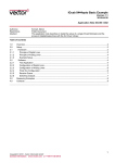
3. Remove the DIMM’s Cover (See Page 8-77) and check the green
and red Status LED’s on the Main PCA. If they are both NOT lit,
replace the Power Supply Unit Page 8-88.
Status
LED’s
4. Check that the Front-Panel Cable is correctly connected to the
Electronics Module. Also make sure that the Front-Panel Cable is
not damaged.
HP DesignJet 5000 and 5500 Series Printers Service Manual
1-5
Troubleshooting
ALL the Front-Panel LEDs are Lit but Nothing Else
Happens
The BootROM DIMM is NOT correctly installed or is the wrong type.
1. Power OFF the Printer from the back and disconnect the Power
Cord. Reseat the BootROM DIMM (looking from the rear of the
Printer, the first slot from the left - See Page 8-77) making sure
that it is installed correctly.
2. If the problem persists replace the BootROM DIMM Page 8-77.
NOTE
For more information, refer to “Electronics Problems” on page 1-21.
Troubleshooting Media Jams/Printhead Crashes
NOTE
If using HP Coated Media when problem occurred, please also
refer to Page 1-11.
The failure modes “media jam” and “head crash” are grouped
together because in many cases a media jam causes the media to lift
up into the carriage path and cause a head crash, thus causing many
media jam failures to be reported as head crashes.
1. Did the media jam occur when loading media?
If the client has had media jams, it is common for pieces of media
to get stuck in the media path. Clear the media path.
NOTE
When clearing a media jam, sometimes media is stuck in the
paper path. To clear this, you must lift the media lever and insert
thicker media into the paper path to push out the media that is
still stuck there.
2. Is the customer using non-HP media?
The use of non-HP media can easily be the cause of media jams and
head crashes (especially head crashes because HP media is
specially formulated to avoid cockle, one of the primary causes of
head crashes). If the media is not HP approved, advise the customer
to use HP media and check to see if the problem is now solved.
3. The Carriage is at the incorrect height in relation to the Center
Platen. Adjust the carriage to the correct height Page 5-18 and try
to load the media again.
4. Check that the Vacuum Fans work correctly - Refer to Page 1-10,
Problems with Vacuum .
1-6
HP DesignJet 5000 and 5500 Series Printers Service Manual
Troubleshooting
Troubleshooting Shutdowns - User Message
"Warning: Switch Power Off"
If a shutdown occurs, you will get the message “Warning: Switch
Power Off” followed by:
Check Printhead Cleaner Path.
Check Paper Path.
Check Printhead Path (followed by (1), (2) or (3)).
A shutdown in each path will require different steps to resolve the
problem as explained as follows.
WARNING
In each case, make sure that you power OFF the Printer before
attempting any procedures to resolve the problem.
Check Printhead Cleaner Path
This message appears whenever the Service Station Carriage does
not move, either because of a bad cable connection, a defective
motor or because of some obstacle inside the Service Station.
If the Printer is new, check that the Service Station cable (which is
the grey flat cable with the grey connector) is plugged into the Main
PCA. Make sure that the clips of the connector are closed
completely. Check also that the Service Station cable is not damaged.
In already used Printers, power OFF the Printer and try to move
the Service Station backwards and forwards to see whether it is
blocked. Possible causes are: Printhead Cleaners incorrectly
positioned, damaged or, even, pieces of paper within the Service
Station. Remove the Printhead Cleaners or the pieces of paper
and check whether the problem persists.
If the problem disappears without the Printhead Cleaners, reinsert them
into the Service Station and see whether the problem reappears. If the
problem reappears, replace the complete set of Printhead Cleaners.
If the problem persists even without the Printhead Cleaners, then
replace the Service Station (Page 8-69) and recalibrate the Printer.
HP DesignJet 5000 and 5500 Series Printers Service Manual
1-7
Troubleshooting
Check Paper Path
This warning appears whenever the friction on the Paper-Axis is too
high: the electrical current needed by the Paper-Axis Motor to move
the paper is too high, so before burning the motor or the Main PCA,
this warning appears. The common reason for this error is an internal
paper jam or at the end of a roll of media the paper is glued to the
media core. It can also be due to a defective motor or Main PCA.
Check that there are no pieces of paper left inside the Printer,
especially if it happens after a paper jam.
NOTE
One way to verify this easily is to take a rigid sheet of paper and
move it along the paper path with the media load lever lifted.
Also, check that the customer has inserted the spindle hubs
completely, otherwise they may rub against the side plate and
increase the friction.
If the error still persists, check that the Paper-Axis Motor cables
are connected correctly and that they are not damaged.
If the Printer still fails, replace the Paper-Axis Motor Page 8-105.
NOTE
Turn the Drive Roller by hand once the motor is removed to
verify that it turns smoothly. Also, after replacing the Paper-Axis
Motor, perform the Media-Axis Test ( Page 4-12and check that
the values are within the given limits.
If the Printer still fails, replace the Main PCA Page 8-81.
Check Printhead Path (1)
This warning appears whenever friction on the Scan-Axis is too
high: the electrical current needed by the Scan-Axis Motor to move
the Carriage is too high, so before burning the motor or the Main
PCA, this warning appears. The usual reason for this error is an
internal paper jam, an obstacle in the Printhead path, a broken belt,
badly installed Ink Supply Tubes, etc.
Apply Oil along the complete axis of the Slider Rods with the
User’s Slider Rods Lubrification Kit Page 9-8.
Also, switch OFF the Printer and move the Carriage from side to
side to verify that it moves smoothly.
If the Printer still fails, check that the Scan-Axis motor is connected
correctly to the Main PCA and that the cable is not damaged.
If the error remains, replace the Belt (Page 8-46) or the ScanAxis Motor Page 8-57.
1-8
HP DesignJet 5000 and 5500 Series Printers Service Manual
Troubleshooting
NOTE
Also, after replacing the Scan-Axis Motor, perform the Scan-Axis Test
(Page 4-10and check that the values are within the given limits.
If the Printer still fails, replace the Main PCA Page 8-81.
Check Printhead Path (2)
This is a safety shutdown and occurs whenever there is a discontinuity
in the Printhead path, because of an obstacle, oil drops on the Encoder
Strip, the Carriage cover touching the tube guides, etc.
Switch OFF the Printer and move the Carriage from side to side
to verify that it moves smoothly.
If it still fails, check the Encoder Strip and, if necessary, clean it.
Check Printhead Path (3)
This is always caused by high friction in the Printhead path. Only in
very special cases, when it happens inside the Left Hand Cover,
incorrect assembly of the tube system causes it.
Apply Oil along the complete axis of the Slider Rods with the
User’s Slider Rods Lubrification Kit Page 9-8.
Replace Message "xx15 Replace" and "xx16 Replace"
In certain circumstances (e.g. Printhead crash without Printer
shutdown), the message "xx15 Replace" or "xx16 Replace" may
appear on the front panel. This is due to a temporal disconnection
between the Printhead and the flex circuit in the Carriage Assembly.
Clean the Printheads and the Carriage interconnects (refer to page
9-6, Carriage Interconnect Wiper ) and reseat the failing Printheads.
HP DesignJet 5000 and 5500 Series Printers Service Manual
1-9
Troubleshooting
Problems with Vacuum
If you have problems loading either Roll or Sheet Media, then there
could be a problem with the Vacuum Fan or Booster Fan. To verify
if there really is a problem with Vacuum, try the following:
1. With the Printer ON, open the Window of the Printer and place a
sheet of HP High Gloss Photo Paper (must be D-Size), aligned with
the blue lines on the Center Platen. If the Vacuum holds the sheet in
place, and then loads it correctly, then the Fans function correctly. If
the Vacuum does not hold the sheet in place (no suction), then try
the following:
Check that the holes in the Center Platen are NOT blocked.
Clean the Overdrive using the Platen Cleaning Utility Page 9-9.
Check that the Vacuum and Booster Fans are installed correctly.
Replace the Vacuum Fan Page 8-103.
Replace the Booster Fan Page 8-108.
2. If the Vacuum held the sheet in place, but couldn’t correctly load it,
then there could be a problem with the Overdrive. In this case,
replace the Center Platen Assembly Page 8-117.
Vacuum suction much lower at high altitudes
At altitudes above 2,000 meters, the vacuum force holding down the
media will be lower, therefore the media will not be held in place
properly causing:
Ink Smearing on the Media.
Printhead crashes against the Media.
Cut Sheet loading problems (high probability).
Roll Media loading problems (low probability).
To solve the problem, try the following:
Using the “1.3 Altitude Setup” in the Service Utilities, set the
altitude to “1.3.2 2000 m or more” (see Altitude Setup 4-23).
1-10
HP DesignJet 5000 and 5500 Series Printers Service Manual
Troubleshooting
Printhead Crashes/Smears on High Density Prints
Using Coated Media
High density prints can cause cockle mainly on HP Coated Media.
This causes two main problems:
1. Cockling in the borders - Because the Printer places too much ink
on the Coated Media, the borders of the print become raised,
causing the Printhead to crash against the media. To solve the
problem, try the following:
Try using Heavy Weight Coated Media instead of Coated Media.
Change the paper margins to “Extended” in the Printer Setup
menu/Page Format/Margins or in the Driver. If the customer is
printing PostScript images, send them a PPD file containing the
extended margins.
Use the Deflectors.
Upgrade the Firmware Page 9-11.
2. Cockling within the print - If the Printer places too much ink within
the print, the media starts to ripple, causing the Printhead to smear
against the media. To solve the problem, try the following:
Never use HP Coated Media for High Density prints. As a
substitute use HP Heavy Weight Coated or Heavy Weight Coated
(Economy) Media.
Color differences in different HP DesignJet Printers
Color differences between one image printed on the HP DesignJet
5000 Series and the rest of the DesignJet platforms are due to the
different chemistry of the 5000 series inks compared with the rest of
the inks for other printers. This color variability among different HP
DesignJet Series Printers has been always present. You can try to
achieve consistent colors with the following:
Select the same color emulation settings in your Postscript Driver
as the one used by the printer you want to emulate.
Select the correct Ink Emulation from the Printer Setup Menu/
Internal RIP Settings.
HP DesignJet 5000 and 5500 Series Printers Service Manual
1-11
Troubleshooting
Banding at variable extreme environmental conditions
The Accuracy Calibration has been done at normal environmental
conditions, therefore printing in extreme environmental conditions
will cause banding because the advance of the Drive Roller does not
correspond to the same conditions that the calibration was done in.
To solve the problem, try the following:
Perform the Accuracy Calibration in the new environmental
conditions (Refer to the User’s Guide - Media Solutions).
Banding with unsupported Media
The Accuracy Calibration has not been done for the Media now
loaded. Banding may occur because the advance of the Drive Roller
does not correspond to the same conditions that the calibration was
done in. To solve the problem, try the following:
Select the Media loaded in the “Media Options” menu and
perform the Accuracy Calibration (Refer to the User’s Guide Media Solutions).
Banding due to Ink Cartridge replacement while
printing
A user has removed the Ink Cartridge while the Printer was printing,
which has caused the Printer to stop. If the user does not replace the
Ink Cartridge immediately, when the Printer starts to print again, a
band will appear in the position where the printing restarted. This is
because the wet ink interacts with the dried ink on the media
causing the band to appear. To solve the problem, try the following:
Do NOT remove the Ink Cartridge while the Printer is Printing.
Only replace/remove Ink Cartridges in between Prints.
If the Ink Cartridge was replaced due to the “Empty” status on the
Front Panel, then advise the customer to replace the Ink Cartridge
when the “Very Low” status is showing on the Front Panel.
1-12
HP DesignJet 5000 and 5500 Series Printers Service Manual
Troubleshooting
Hue shift on HP Colorfast Adhesive Vinyl media
Under high humidity conditions (approx. >65%) the colors tend to
fade over time, particularly colors that require Magenta. To solve
the problem, try the following:
Reduce the level of humidity (<65%) that the Printer is working
in. To find the humidity level, print the Service Configuration
Print (Printer Setup Menu / Utilities / Test prints / Service config).
Laminate the prints.
Black Smearing on HP Photo Imaging Gloss
Narrow black lines can smear on this type of media, particularly if
the lines are narrow and have white gaps in between them. Try the
following:
Increase the Dry Time using the Front Panel (Refer to the User’s
Guide).
Laminate the prints.
Magenta Bleeding on HP Photo Imaging Gloss when
using the Take-Up Reel
Under high humidity conditions (approx. >70%) this media reduces
its capacity to absorb Magenta because of this color’s particular
characteristics. When an area fill with magenta is printed and then
rolled onto the Take-Up Reel the ink that is not completely dry
moves laterally on the media. To solve the problem, try the
following:
Reduce the level of humidity (<70%) that the Printer is working
in. To find the humidity level, print the Service Configuration
Print (Printer Setup Menu / Utilities / Test prints / Service config).
Increase the Dry Time using the Front Panel (Refer to the User’s
Guide).
Do not use the Take-Up Reel or Bin for this media when
humidity levels are high.
HP DesignJet 5000 and 5500 Series Printers Service Manual
1-13
Troubleshooting
Loss of Gloss on HP Photo Imaging Gloss when using
the Take-Up Reel
Under high humidity conditions (approx. >70%) the polymer chain
in the coating of this media relaxes and the drying rate decreases. If
the printed media is rolled onto a Take-Up Reel or is covered by
another print, the contact between the two surfaces could cause
blotches in the gloss. Try the following:
Reduce the level of humidity (<70%) that the Printer is working
in. To find the humidity level, print the Service Configuration
Print (Printer Setup Menu / Utilities / Test prints / Service config).
Increase the Dry Time using the Front Panel (Refer to the User’s
Guide).
Do not use the Take-Up Reel or Bin for this media when
humidity levels are high.
Dry Cockle on High Density Prints Using Paper Based
Media
High density prints can cause dry cockle mainly on Paper Based
Media.
To solve the problem do the following:
Use the Take-Up Reel and Take-Up Reel deflectors.
Set the Printer to Productivity mode to reduce the ink density.
Select Coated media modes
If the problem persists, try the following:
Laminate the prints.
Use a heavier media that is more suitable to high ink density,
such as HP Paper based Semi-Gloss or HP Poster Paper.
1-14
HP DesignJet 5000 and 5500 Series Printers Service Manual
Troubleshooting
Wrinkles and scratches (cockle) on HP Coated and
Heavyweight Coated Media.
Images may be damaged if prints are not handled with care,
particularly when handling wide plots. This can happen when
images are placed on top of one another and there is movement
between them, causing friction and loss of ink from the surface if it
is not completely attached. Also, if plots are rolled up, wrinkles can
occur. To avoid this problem try the following:
Always handle plots with care.
Use of the Take-Up Reel eliminates handling and avoids
wrinkles.
Use heavier media.
For Heavyweight Coated media, select faster print modes such as
Heavyweight Coated (Economy) for Media selection, and/or
Productivity Print mode.
If damage is slight, Lamination will help towhead’ defects.
Use of Fixative Sprays immediately after printing may protect the
image.
Worm marks (cockle) on part of plots on paper based
media
At high temperatures and under dry conditions, worm marks may
occur on initial parts of plots when printing solid fill areas in
medium tone colors. Try the following:
Advance the media manually by 15 mm.
Select Heavy Coated for Media setting.
Select Productivity mode to reduce ink density.
HP DesignJet 5000 and 5500 Series Printers Service Manual
1-15
Troubleshooting
Drying Time Too Long for HP Studio Canvas
Under conditions of high humidity (> 70%) HP Studio Canvas
retains a high amount of water and takes too long to dry, also
creating problems in using the Take-Up Reel and Bin. To solve the
problem try the following:
Reduce the level of humidity (<70%) that the Printer is working
in. To find the humidity level, print the Service Configuration
Print (Printer Setup Menu / Utilities / Test prints / Service config).
Increase the drying time using the Front Panel settings (Refer to
the User’s Guide).
Do not use the Take-Up Reel or Bin under conditions of high
humidity.
Media Skew when Printing a Banner Plot
When printing banners, media skew occurs. This is particularly
noticeable in the first plot when media is not perfectly aligned. To
solve this problem do the following:
Use extended margins for banner plots (Refer to the User’s
Guide).
User message "Media loaded incorrectly. Remove
media"
This message appears when the media sensor has detected media,
but the line sensor has not detected the leading edge of the media at
all or has found it in an incorrect position.
There are three possible situations when this message comes up:
1. The paper is in the incorrect position because the Printer was turned
OFF in the middle of a print. It should only happen in printers
without the Take-Up Reel (42" model), because with the Take-Up
Reel installed the Printer will not search for the leading edge after
the Printer has been powered-up or after activating the media load
lever. The Printer simply continues to print wherever it stopped.
To verify this setting, check in "Printer Setup Menu > Device
setup > TUR installed". It should be set as No for the 42" model
Printers and Yes for the 60" model Printers.
1-16
HP DesignJet 5000 and 5500 Series Printers Service Manual
Troubleshooting
2. The media sensor is defective. To verify this, remove the media and
re-boot the Printer. If the message comes up during initialization,
the media sensor is defective. To solve this, try the following:
Check that the media sensor cable is connected correctly
Check that the media sensor cable is not damaged and that the
media sensor is clipped correctly.
Replace the Media Sensor Page 8-109.
3. The Line Sensor does not detect the leading edge of the media. To
verify this, load media (ideally white media such as Coated or PhotoGloss) into the Printer. If the message comes up during the loading
process, the Lens Cover Assembly is either not installed correctly or
it is dirty. In this case, replace the Lens Cover Assembly Page 9-5.
If this fails, replace the Carriage Assembly Page 8-46.
User message "Warning: Incorrect type of tubes system"
This error message appears if the electrical connector of the Ink
Tubes System is not connected correctly (especially after the Tubes
have been replaced). Other causes are defective EEROM in the Ink
Tubes System or ISS PCA.
Switch OFF the printer, open the rear left cover and connect or
re-connect the Electrical Cable (the colored flat cable) that is
connected to the rear of the Ink cartridge Tube Connector.
If the problem persists, check that the Electrical Cable is
connected correctly to the ISS PCA.
Replace the ISS PCA (Page 8-91) or the Ink Tubes system (
Page 8-25).
User message "Power Supply Error #1"
This error indicates a short in the 24V electronics circuits. Do not
replace the Power Supply; This message only indicates the failure,
and is not the cause. Usually this message appears after the insertion
of a Trailing Cable into the connectors. This message means that the
Trailing cable is incorrectly connected, and it is creating a short on
the 24V circuit.
To isolate the problem, remove the Trailing Cable from the back of
the Printer and check whether the Printers powers up correctly.
If the Printer powers up correctly, the problem could have been a bad
HP DesignJet 5000 and 5500 Series Printers Service Manual
1-17
Troubleshooting
Trailing Cable connection, so just reconnect the Trailing Cable again
to double-check that the Printer now works. If, after reconnecting the
cable, the error appears again, either the Carriage PCA or the
Trailing Cable is defective. In this case, first try replacing the
Trailing Cable and then the Carriage Assembly.
If the Printer did not initialize correctly, even after removing the
Trailing Cable, the problem is either in the Main PCA or the ISS
PCA. So, once again, to isolate the failure, disconnect first the ISS
cable and check whether the Printer works. If it does, reconnect the
cable again to verify the failure and then, if necessary, replace either
the ISS cable or the ISS PCA.
If the Printer still does not initialize, even after removing the Trailing
Cable and the ISS cable, replace the Main PCA.
1-18
HP DesignJet 5000 and 5500 Series Printers Service Manual
Troubleshooting
Cutter Assembly Problems
1. The Printer does not cut (even when using the Form Feed & Cut
option in the Front Panel).
In this case it is very likely that the cutter is disabled in the EEROM.
This can happen whenever the Diagnostic Print is cancelled in the
middle of the print, or if the Printer was turned OFF in the middle of
the Diagnostic Print.
To re-activate the Cutter, print the Diagnostic Print again and this
time letting it finish to the end without any interruptions.
If the Cutter still doesn’t cut after re-printing the Diagnostic
Print, replace the Cutter Assembly Page 8-60.
NOTE
This problem is solved in any A.02.xx firmware release.
2. The Cutter does not cut thick paper (Canvas & Non-HP Media).
As in all DesignJets, the Cutter can only cut media up to a certain
thickness (such as Heavy Coated or Photo paper). Thicker media or
special media (such as Canvas) cannot be cut.
Taking this into consideration, when Canvas is selected on the
front panel, the cutter is automatically disabled, but there is
nothing wrong with the cutter.
3. The Printer hangs while cutting.
The Printer hangs and the Carriage stops if the window is opened
during the cutting operation. In addition, when pressing any key, the
Error Code ffff ffff 03450097 may appear on the front panel.
Re-boot the Printer and make sure the customer does not open the
window while the Printer is cutting.
NOTE
This problem is solved in any A.02.xx firmware release.
HP DesignJet 5000 and 5500 Series Printers Service Manual
1-19
Troubleshooting
Carriage and Scan-Axis Problems
1. Printhead continuity problems.
When installing the Ink Tubes System, it is possible that the crane
(the part of the Tubes System that is connected to the front of the
Carriage) is not clipped properly. This can cause Printhead continuity
problems afterwards, especially in the light cyan and light magenta
Printheads (XX16 REPLACE message appears for these Printheads).
Whenever there is a Printhead continuity problem, always check
that the crane is completely clipped to the front of the carriage.
2. Unknown Line Sensor ID.
When performing the Scan-Axis Calibration, the Printer asks for the
Line Sensor ID. But there is no label on the Line Sensor indicating it.
If the Line Sensor ID is not indicated on the Line Sensor, use the
default value which is "0". In the future, if the LED’s are
modified, a sticker will be included with the new Line Sensor ID.
3. Line Sensor is shown as "Not calibrated" in the Service
Configuration Print.
This is a firmware bug. It is possible that the Line Sensor is
calibrated even though the Service Configuration Print indicates
that the Calibration has not been performed.
Just ignore this information about the Line Sensor calibration.
If there are any errors related to the Line Sensor, perform the
Scan-Axis calibration to make sure that the Line Sensor
calibration is completed.
Media-Axis Problems
1. Printer unloads media (it suddenly starts to rewind and unloads the
media)
If the window was raised at exactly the same moment when the
Printer moved the media (e.g. during media loading) from that
moment onwards the Printer will always reject the media unless the
Printer is turned OFF and then back ON again.
Problem disappears after re-booting the Printer.
NOTE
1-20
This problem is solved in any A.02.xx firmware release.
HP DesignJet 5000 and 5500 Series Printers Service Manual
Troubleshooting
Electronics Problems
1. The Printer hangs with the front panel completely blank and the
three Image Quality LED’s lit.
The firmware has a bug that creates this situation whenever the
Printer is receiving data from an external RIP.
The customer should print using the HP Driver to check that the
Printer is printing without any problems.
The only solution to this problem will be to upgrade to the
firmware for the UV inks (A.02.XX) when it is available.
NOTE
This problem is solved in any A.02.xx firmware release.
2. The Printer hangs at "Initializing Please Wait".
The Printer hangs showing the following front panel message for
more than 5 minutes: "Initializing Please Wait, Code Rev. xxxx,
Boot ROM. xxx, etc".
The cause for this failure could be either a print sent through the
Parallel or LAN port during initialization, or a defective I/O card.
Power OFF the Printer, disconnect the Parallel and/or the
Network cable and power ON the Printer again to see if the
Printer hangs again.
If the Printer did not hang again, then the problem was due to the
Printer receiving data through the ports while the Printer was
initializing. Before connecting the cables again, make sure that
all the pending print jobs are purged.
If the Printer did hang again, then power OFF the Printer, remove
the I/O card and power ON the Printer again to see if the Printer
still hangs.
– If the Printer did not hang again, install the I/O card in the
second slot and check whether it works there. If the I/O card
causes the Printer to hang again, replace the I/O card. If the
Printer continues to hang, even with a new I/O card, then
replace the Main PCA Page 8-81.
HP DesignJet 5000 and 5500 Series Printers Service Manual
1-21
Troubleshooting
3. The Printer is printing slower compared to another HP DesignJet 5000.
It is important first to determine whether the differences are during
receiving/processing, during printing or once the print is finished.
1. The time the printer takes to start printing is longer.
Check that the "Start printing option" is set the same for all
Printers.
NOTE
For troubleshooting purposes, set this option to "After Processing".
In this way the time reported is the time needed to receive the data
and to process it and the printing time is not taken into account.
If there are differences still, it is probably due to the customer’s
network configuration.
NOTE
Make sure that the Printer is not processing or printing another job
while doing this test, because this might have affect the outcome.
Once finished, return the Printer to the recommended setting,
which is "Optimized".
2. The actual printing time is slower.
This may be due to the Carriage stopping at the end of each swath,
one Printer making more passes or the Carriage moving slower.
Check that the dry time is turned off.
NOTE
If the dry time is turned ON, the Carriage might stop at the end of
each swath, because the Printer uses the dry time (i.e. the humidity
and temperature reading) to adjust the printing speed. This is
necessary to ensure that the print is completely dry before it can
either touch the Media Bin or is rolled up with the Take-Up Reel.
Check that the Image Quality setting on the front panel (while the
Printer is printing) is the same for all Printers.
NOTE
The setting while the Printer is in the stand-by mode might be
different to the actual LED that lights up during printing.
Check that the Image Quality setting in the Driver is the same for
all the Printers.
Check that the memory size, shown on the front panel, is the
same for the Printers that are being compared. (Standard
configuration: 192Mbyte for C6096A and 128Mbytes for
C6090A/C6091A/C6095A).
1-22
HP DesignJet 5000 and 5500 Series Printers Service Manual
Troubleshooting
3. The dry time at the end of the print is longer.
Normally the Printer uses the temperature and the humidity reading
from the ISS PCA to calculate the dry time, which is required for
the print to dry before being cut. The specification of these readings
is +/- 15%, so a variation in the calculated dry time of up to 30% is
within specification.
To check the correct functioning of the sensor, print the "Service
Configuration Print" and check that both the temperature and
humidity readings are correct (i.e. within the specification). If
not, replace the ISS PCA Page 8-91.
As an alternative solution, turn OFF the dry time, and then all the
Printers should finish the print at the same time.
Another alternative is to set the dry time manually on all the
Printers.
NOTE
This dry time will be applied to all the prints.
Language Selection is blocked in a brand new printer
Normally the user has about 2 minutes (initialization time) to select
the language in the Front Panel. If the language is not selected
within this time period, the Front Panel is locked.
To recover from this problem, just re-boot the Printer and select
the language within the specified time (2 minutes).
Firmware Upgrade Does Not Work Through the
Parallel Port
With firmware revisions A.01.10, 11 & 12, the Printer will remain at
90% when doing a Firmware upgrade via the parallel port.
For the customer, recommend using the network to print and to
perform the Firmware upgrade.
For Service Engineers:
– Keep the "Top Arrow" key on the Front panel pressed down
when turning the Printer ON, and release it once the "Boot
Menu" appears.
– Select "Upgrade Firmware" in the Boot Menu.
– Send the firmware through the parallel port.
NOTE
This problem is solved in any A.02.xx firmware release.
HP DesignJet 5000 and 5500 Series Printers Service Manual
1-23
Troubleshooting
Typical Failures After Exchanging the Ink Tubes
The following table contains typical failures that could appear after
changing the Ink Tubes:
Failure
Description
Solution
After completing the
initialization process, the Front
Panel displays:
WARNING
Incorrect type of Tubes
System
Switch power off
The electrical
connector has not
been correctly
connected to the Ink
Cartridge connector.
1 Switch OFF the Printer.
2 Connect the electrical
connector into the Ink
Cartridge tube connector.
3 Switch ON the Printer.
When you try to print, the
Front Panel displays:
System Error
0a0000 00000002
Contact HP Representative
The air tube has not
been correctly
connected to the Ink
Cartridge connector.
1 Switch OFF the Printer.
2 Connect the air tube into the
Ink Cartridge tube connector.
3 Switch ON the Printer.
When you try to insert an Ink
Cartridge, you keep getting the
following message for one or
more Ink Cartridge:
XX02 Reseat
The three latches at
the rear of the Ink
Cartridge tube
connector have not
been locked correctly.
1 Remove the Ink Cartridges.
2 Open the door at the back of
the Left Hand Cover.
3 Correctly lock the 3 latches.
4 Close the door and insert the
Ink Cartridges.
When you try to insert a
Printhead, you keep getting the
following message for one or
more Printhead:
XX02 Reseat
The Printhead tube
connector has not been
correctly connected to
the Carriage Assembly.
1 Remove any Printhead(s).
2 Make sure the Printhead tube
connector is fully connected
to the Carriage Assembly.
3 Insert the Printheads.
When you try to insert a
Printhead, you keep getting the
following message for one or
more Printhead:
XX11 Reseat
Normal Printheads are
being inserted BUT
the Printer requires
Setup Printheads to
prime the Ink Tubes.
1 Insert the Setup Printheads
provided with the HP
Upgrade Kit that allows
automatic printing.
After you have inserted the
Printhead Cleaners, the Front
Panel displays the following
message:
XX05 Replace
The wrong type of
Printhead Cleaners
have been inserted for
the type of Ink System
installed in the Printer.
1 Remove the Printhead
Cleaners.
2 Make sure that they are of the
same type as the rest of the
consumables (No.81 or
No.83).
3 Replace the incorrect ones.
1-24
HP DesignJet 5000 and 5500 Series Printers Service Manual
Troubleshooting
Solving Media-Handling Problems
NOTE
HP Designjet Printers minimum media size is A3 in portrait
mode.
The Front Panel Keeps Indicating that Media Is Misaligned or
Incorrectly Positioned
Roll media
The roll may be loaded the wrong way. The paper should load
over the roll toward you.
The media may be crumpled or warped or have irregular edges.
The paper may be loaded at an angle. The right-hand edge must
be parallel to the blue line on the paper entry roller.
WARNING
Ensure that the paper is wrapped tightly on the roll. This is a
very important step to remember because if this is not done, the
media may be loaded at an angle, causing the media to be
rejected.
Perform the manual alignment procedure (Refer to the User’s
Guide).
Check that the paper is correctly loaded onto the spindle.
Sheet media
It must be loaded with the right-hand edge against the blue
perforated line on the Printer.
Align the media against the trailing edge coming out of the
Printer.
The media may be crumpled or warped or may have irregular
edges.
If you are using hand-cut media, the edges may not form a rightangle or they may be rough. Do not use hand-cut media. Use only
purchased sheet media.
If the media you are trying to load is very slippery, hold the
media with both hands, and gently push the media into the Printer
until it buckles upwards in the middle, this will help the Printer to
load it.
If the Overdrive is covered in dust, it will have problems picking
up the sheet media during the load process. Clean the Overdrive
using the Platen Cleaning Utility Page 9-7.
Prints Do Not Stack The Printer may be too close to the end of the roll. The natural
Properly in the
curl near the end of the roll can cause stacking problems. Load a
Media Bin
new roll or remove prints manually as they are completed.
If you are mixing prints or nesting sets of several different sizes,
you may have stacking problems because of the different sizes of
media in the bin.
HP DesignJet 5000 and 5500 Series Printers Service Manual
1-25
Troubleshooting
How to Navigate through the Front Panel Menus
Shaded boxes always appear in the front panel. White boxes appear
only in Full menu mode.
I/O Setup Menu
I/O setup
No I/O card found
Card ID
Card ID
Card Setup
Card Setup
Configuration
Advanced
Reset Card
0.5 min .. 30 min
I/O timeout
@
Only Appear in
Full Menu Mode
1-26
Always Appear
PostScript Only
HP DesignJet 5000 and 5500 Series Printers Service Manual
1-27
Always Appear
Only Appear in
Full Menu Mode
Device Setup
On, Off
HP-GL/2
Reduced Margins
Lang
Drying Time
On, Off
Cutter
@
PostScript Only
255 .. 2, 1 min
Only Appear if TUR
is Not Loaded
Only Appear if TUR is
installed and Loaded
Manual
Automatic, None
PostScript@, Automatic
NO,YES
TUR Installed
Troubleshooting
Device Setup Menu
HP DesignJet 5000 and 5500 Series Printers Service Manual
Utilities
1-28
Print usage, View usage
Short, Full
Printhead alignment,
Usage
Menu Mode
Calibrations
Automatic, Manual
PS Code Rev, PS Font code
Up, Down
Automatic clean
Clean now …
Default Menu
Display Contrast
Clean Platen
Lens Maintenance
On, Off
Ram present, Service ID
Hard Disk, Code Rev.
Statistics
Recalibrate
HP-GL/2 config
Service config.
Usage report
Print Quality
Restore factory
Test Prints
Accuracy
Color Calibration
Yes, No
Track Media Length
Reset Web Svr Passwd
No (Continue), Yes (Replace)
Replace Ink System
Create Pattern
Measure Pattern
Troubleshooting
Utilities Menu
HP DesignJet 5000 and 5500 Series Printers Service Manual
1-29
100% .. 419%, Fit to page
PS scale
Always Appear
PS encoding @
@
@
PostScript Only
@
Software, Binary, ASCII
Off,On
Enhanced res
@
Off,On
Black Replacement
@
Off,On
@
Color calibration
CMYK
RGB@
Ink Emulation
@
Optimized, Immediately
After processing
Start printing
Only Appear in
Full Menu Mode
Internal RIP Settings
Native, EuroScale,
SWOP, TOYO,
@
DIC
Native, sRGB,
@
Apple RGB,
Adobe RGB,
ColorMatch RGB
Troubleshooting
Internal RIP Settings Menu
HP DesignJet 5000 and 5500 Series Printers Service Manual
Nesting
1-30
Only Appear in
Full Menu Mode
Nest
Queue mgmt
Always Appear
In order ...
Off
# ....
@
width, Length
Statistics
PostScript Only
99 .. 2, 1 min
Move to top,
Delete Page
99 .. 1,0
Copies
Troubleshooting
Queuing and Nesting Menu
HP DesignJet 5000 and 5500 Series Printers Service Manual
HPGL/2 settings
HP DesignJet 5000 and 5500 Series Printers Service Manual
Only Appear in
Full Menu Mode
Always Appear
Width
Width
PostScript Only
@
Factory
On/Off
Pen no. 0 … 15
Palette A, Palette B
Define Palette
Merge
Pen no. 0 … 15
Software, Factory, Palette A, B
Palette
255 .. 1, 0
0.13 ... 12.0mm
Troubleshooting
HP-GL/2 Settings Menu
1-31
1-32
Always Appear
On, Off
@
30 .. 5, 0 mm
PostScript Only
Automatic
Nest Spacing
Mirroring
Normal, Extended
Margins
Manual
0 .. 270
Best ISO A, ISO A4 .. A0
Best JIS B, JIS B4..B1
JIS
ISO
Best ARCH, ARCH A.. E1
Arch
Best ANSI, ANSI A ..E
Over A2, Over A1
Oversize
ANSI
1.0X1.4m
42inX59in 44X62in
1.2X1.7m 52X73in
54X76 60X100in
Extrawide
Inked Area, Software
Rotate
Size
Only Appear in
Full Menu Mode
Page Format
Troubleshooting
Page Format Menu
HP DesignJet 5000 and 5500 Series Printers Service Manual
Troubleshooting
HP DesignJet 5000 and 5500 Series Printers Service Manual
PostScript Only
Always Appear
Only Appear in
Full Menu Mode
Menu
Palette
Demos
Samples
@
Demos Menu
1-33
1-34
HW Coated (Economy)
HW Coated
Coated Paper
Photo Imaging Gloss
Colorfast Vinyl
Paper Semi-Gloss
Poster Paper
Studio Canvas
and more.......
*HW Coated (Economy)
*HW Coated
*Coated Paper
*Photo Imaging Gloss
*Colorfast Vinyl
*Paper Semi-Gloss
*Poster Paper
*Studio Canvas
and more.......
Media Selection
Delete Media
Yes, No
Yes, No
TUR Loaded=
Form Feed & Cut
Move Media
Vendor Name
Type of Media
Width
Printable Area
Profile Revision
Roll/Sheet Info.
Troubleshooting
Media Menu
HP DesignJet 5000 and 5500 Series Printers Service Manual
HP DesignJet 5000 and 5500 Series Printers Service Manual
Replace Ink Cartridge
Light Cyan cart Info
Light Magenta cart Info
Yellow cart. Info
Cyan cart Info
Magenta cart Info
Black cart Info
Yes, No
Ink Level
Capacity
Part Number
Manufacture Date
HP No. 81 Ink Cartridge
Troubleshooting
Ink Cartridge Menu
1-35
Troubleshooting
Printhead Menu
Printhead Info
1-36
Light Cyan Info
Light Magenta Info
Yellow Info
Cyan Info
Magenta Info
Black Info
Recover Printheads
All Printheads
Cyan
Magenta
Yellow
Black
Light C
Light M
Replace Printheads
Yes, No
HP DesignJet 5000 and 5500 Series Printers Service Manual
Troubleshooting
Service Configuration Print
The Service Configuration Print is a useful tool for troubleshooting
the Printer. The Service Configuration Print contains the following
information about the Printer:
General Configuration
Printhead Info.
Ink Cartridge Info.
Operating Conditions.
Calibrations.
Maintenance.
I/O Configuration.
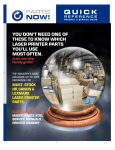
How to Print the Service Configuration Print
1. Load media (Roll media or at least an A0 Sheet) into the Printer.
2. Once the message “Ready” is displayed on the front-panel, scroll to
the “Printer Setup Options” icon and press the Enter key.
Ready
Roll
Hewlett Packard
Photo Imaging Gloss
Ink
Printheads
Printer Setup Options
OK
OK
3. Once inside the “Printer Setup Options” menu, use the Arrow keys
to scroll to the “Utilities” menu display and press the Enter key.
Printer setup options
Device setup...
I/O setup...
Utilities...
Internal RIP settings...
Queueing & Nesting...
HP-GL/2 settings...
Top
Back
n
p
Enter
HP DesignJet 5000 and 5500 Series Printers Service Manual
Make Selection
Press Enter
1-37
Troubleshooting
4. Once inside the “Utilities” menu, use the Arrow keys to scroll to the
“Test prints” menu display and press the Enter key.
Utilities
Utilities
Display
Contrast
...
Calibrations
...
Reset WebAccess
paswd
Contrast
...
Test Prints
Statistics
...
...
Default
menu...
Test
Prints
Display contrast ...
Top
Back
n
p
Press Up
and Enter
Enter
5. Use the Arrow keys to scroll to “Service Config.” and press the
Enter key to print the Service Configuration Print.
How to Use the Service Configuration Print
The Service Configuration Print is divided into 7 different areas
where you can find information to troubleshoot the Printer.
General Configuration - In this area you can find information
regarding the general configuration of the Printer, for example,
the firmware version, amount of memory installed or the capacity
of the Hard Disk Drive.
Printhead Info - In this area you can find all the information
regarding the Printheads, for example, the part number, the
manufacturing date or the number of times a certain Printhead
has been inserted in the carriage. This information is useful for
troubleshooting Printhead problems and even knowing if the
Printheads have been used with Non-HP Ink Cartridges.
Cartridge Info - In this area you can find all the information
regarding the Ink Cartridges, for example, the part number, the
manufacturing date or the ink level. This area also shows you if
the customer is using Non-HP Ink Cartridges.
Operating Conditions - In this area you can find the level of
humidity and the temperature that the Printer is working in.
Calibrations - In this area you can find information on certain
calibrations that have been performed on the Printer. It will also
tell you if a required calibration was performed or not.
Maintenance - In this area you can find information relating to
maintenance, for example, the number times the Printer has been
powered ON, the number of Carriage cycles or the last System
Error Code that was triggered.
I/O Configuration - In this area you can find information on the
configuration of the JetDirect Card.
1-38
HP DesignJet 5000 and 5500 Series Printers Service Manual
Troubleshooting
General Printer Information
1. Interaction between start printing and nesting.
Of the four possible combinations between "Start Printing =
Optimized or After processing" and "Nesting = In order or OFF"
only two are possible. For example, if you have nesting set to "In
order" and you change start printing to "Optimized" the Printer will
automatically change nesting to "Off". Likewise, if you have start
printing set to "Optimized" and you change nesting to "In order" the
Printer will automatically set start printing to "After Processing".
There is no problem. This is the way the Printer operates.
2. Printhead crashes and ink smearing with Coated Paper.
HP Coated Paper is very prone to Printhead crashes especially in
high humidity conditions and high-density prints. The HP
recommendation is as follows:
HP Coated Paper - For presentation-quality images: For a
variety of everyday uses. Produces excellent line and color
quality for medium ink-density illustrations and graphics,
working comps, proofs and renderings.
HP Heavyweight Coated Paper - For durable, presentationquality images; Designed for high ink-density and rugged use, and
for final presentations and signs that are mounted and laminated.
3. Throughput
Maximum Throughput given in the Technical Data Sheet for HP
Coated Paper is:
Print Mode Max Speed (60 inch model): 569 sqft/hour*
Print Mode Max Speed (42 inch model): 499 sqft/hour*
NOTE
These are maximum mechanical printing speeds and do not
include, for example, printhead servicing at the beginning/end of
the print, dry time at the end of the print, etc. So, the average
throughput when you are printing a run of several plots will be
lower.
If you only want to maximize throughput, the following settings
are recommended:
– Dry time: NONE
– Internal RIP settings > Start printing > Immediately
– Print orientation: if possible use Landscape instead of Portrait
to reduce Carriage stops.
– Printhead status: OK to reduce servicing at the beginning/end
HP DesignJet 5000 and 5500 Series Printers Service Manual
1-39
Troubleshooting
of the print. Perform a manual recovery if the Printhead status
is (XX20) RECOVER/ (XX21) REPLACE.
With longer plots, average productivity will increase (i.e. same
area is printed in less prints > reduction of servicing at the
beginning/end of the print).
Troubleshooting Take-Up-Reel Problems
Issue
Right Hand (RH)
Module LED is OFF
RH Module LED is
RED
Main Reason
Action/Check
The Printer is not
connected or switched
ON
Check that the TUR power cord is connected
The Spindle LOCK
Lever is not closed
Check that the TUR Spindle is inserted on the
TUR and the automatic lock is closed
Check that the switch located at the rear side of
the RH Module is ON
Check that the LED turns from RED to GREEN
when manually closing the Spindle Lock Lever
RH Module LED is
blinking REDGREEN
Problem with the RH
Module Sensor
connection
Check that the sensor cable is well connected to
the Sensor Assembly
If the problem persists, call an HP representative
Media is not being
rolled
TUR is ON but is not setup correctly
Check that the RH Module LED is ON (and
GREEN)
Check that the TUR Spindle is inserted and the
Spindle Lock Lever is closed
Media is not supported
or it is not set-up
correctly in the TUR and
the Media skew is
causing problems
Check that the media weights are being used, set to
the media size used and the blue flanges are inserted
on the media weight
Check that the media is stuck to the Spindle as
parallel as possible to prevent skew
Check that the Deflector Bar is correctly installed
and that the Media routing is OK
Check that the media is HP supported.
Transparent media are not supported for being
used with the TUR
Media is being cut
after each print
1-40
The TUR is not set-up in
the Front Panel Menu
Check that the TUR ON option is activated on the
Front Panel (Devices Menu)
HP DesignJet 5000 and 5500 Series Printers Service Manual
System Error Codes
2
System Error Codes 2-3
Introduction 2-3
Continuable and Non-Continuable Error Codes 2-4
System Error Groups 2-4
ffff ffff xxxxxxxx (General Firmware Error) 2-5
ffff ffff 02b301b0 2-5
ffff ffff 01dcxxxx 2-6
ffff ffff 030d0170 or ffff ffff 030d0171 2-6
ffff ffff 031609xx 2-6
ffff ffff 03450097 2-7
ffff ffff 036000bd 2-7
ffff ffff 036e0136 2-7
01002D (Non-Continuable) 2-7
010023 (Non-Continuable) 2-8
010030 034c095e 2-8
010040 2-8
010041 2-9
010042 2-9
010090 (Continuable) 2-10
010091 (Continuable) 2-10
010092 (Continuable) 2-10
011000 2-10
040000 01E603D9 2-11
050000 (Continuable) 2-11
050001 (Continuable) 2-11
06030C 2-12
06040C 2-12
0A0000 2-13
0A0010 2-13
0A0020 2-13
0A0030 2-14
0A0040 2-14
0A0050 (Non-Continuable) 2-15
0A0060 (Non-Continuable) 2-15
0A0070 (Continuable) 2-15
0B0000 2-15
HP DesignJet 5000 and 5500 Series Printers Service Manual
2-1
System Error Codes
0B0001 2-16
0B0002 2-16
0B0003 2-16
0B0004 2-17
0B0005 2-17
0B0006 2-17
0B000X 2-18
0B0010 xxxxxxxx (Non-Continuable) 2-18
0B000A 2-18
0B000B 2-19
0B000C 2-19
0B000D 2-19
0B000E 2-19
0B000F (Continuable) (Only applicable to DesignJet 5500 Series) 2-20
0C0030 2-20
0C0032 (Continuable) 2-21
0C0040 2-21
0C00FF 2-22
0C1000 2-22
0C1001 2-22
0D0000 (Continuable) 2-23
0D0000 033f019C 2-23
0D0002 (Continuable) 2-23
0D0003 xxxxxxxx (Non-Continuable) 2-23
0D0004 xxxxxxxx (Non-Continuable) 2-23
0D0005 03180382 (Non-Continuable) 2-24
0FXXXX (Non-Continuable) 2-24
0F0200 00b007bc 2-24
0F0200 00b007E5 2-24
0F0200 01E603d2 2-25
0F0100 03180382 (Non-Continuable) 2-25
1f500XX (Boot Failed) 2-25
e50000 2-26
2-2
HP DesignJet 5000 and 5500 Series Printers Service Manual
System Error Codes
System Error Codes
Introduction
NOTE
Before troubleshooting System Errors, if possible, repeat the
procedure performed when the error was reported.
NOTE
When reporting the System Error Code, make sure that you
supply the full Error Code and the firmware version (displayed
during the initialization process when powering ON the Printer
or available in the User’s Printer Setup Utilities Statistics
menu).
The following pages contain a list of System Error Codes and their
respective descriptions and recommended corrective actions. Only
try one recommended action at a time and check if the Error Code
has disappeared.
System Error Codes consist of two groups of alpha numerics:
[XXXXXX]-[YYYYZZZZ]
The first set of 6 alphanumeric characters consists of the System
Error and the second set of 8 digits, when present, refer to the
internal error data.
NOTE
If the YYYY digits in the second set of 8 characters are zero
[0000ZZZZ], this indicates a LAN Card System Error. The last
four digits [ZZZZ] of the Error Code must be reported to the
vendor support organization:
For HP JetDirect Cards, this error code must be reported to
the iIPS Division Support.
For 3rd party LAN Cards, the HP support organization should
communicate to the customer that they should address it
through the 3rd party vendor support structure.
HP DesignJet 5000 and 5500 Series Printers Service Manual
2-3
System Error Codes
If you have an error code which is not documented in this Service
Manual or you have an error which you cannot resolve, then report
the error to the HP Response Center or the nearest HP Support
Office. When reporting the error, have the following information
ready:
Which firmware revision the Printer is using.
The complete error number.
Which software application the customer is using (name, version,
etc.).
Continuable and Non-Continuable Error Codes
Some of the Error Codes are continuable, which means you can
press Enter on the front-panel and continue working with the
Printer. Non-Continuable Error Codes do not allow you to continue
working with the Printer, in this case power the Printer OFF and ON
again and see if the System Error disappears. If the Error Code
reappears, then the Printer requires an on-site visit in order to
resolve the problem.
NOTE
Even though the customer can continue working with a
Continuable Error Code, an on-site visit should still be planned
to troubleshoot the problem.
System Error Groups
The System Errors are organized in groups as follows:
Group 01 - Hardware Test Group.
Group 04 - Intelligent I/O (Jetdirect) Errors.
Group 06 - Line Sensor Errors.
Group 08 - Pen Energy and Thermal Management Errors.
Group 09 - Hard Disk Drive Errors.
Group 0A - Ink Delivery System Errors.
Group 0B - Hardware Initialization Errors.
Group 0C - Drop Detection/Nozzle Recovery Related Errors.
Group 0D - Miscellaneous Errors.
Group 0F - Firmware/Software Errors.
2-4
HP DesignJet 5000 and 5500 Series Printers Service Manual
System Error Codes
System Error:
ffff ffff xxxxxxxx (General Firmware Error)
Problem
Description:
All ffff ffff errors are general firmware errors. This does not mean
that the firmware has failed, but that the firmware (as a piece of
software) has experienced an internal crash and before doing
anything incorrectly it displays this error. We can compare this to the
"blue-screen" that appears in the Windows operating system when
there is a software problem. These errors also mean a system crash.
Usually, the errors are sporadic and appear very randomly. The best
solution is just to switch the Printer OFF and ON and check if the
problem has disappeared (as in Windows). Frequently, the problem
will disappear.
However, sometimes the same system error appears quite often or it
is permanent. Its root cause (as explained above) may not
necessarily be a firmware problem; it could also be related to the Ink
Supplies, Electronics Module, etc.
In this situation, please take note of the Firmware version, the
situation where the problem can be reproduced and the
COMPLETE system error code and report it to the division.
Corrective Action:
Try the following:
Power-cycle the Printer and to check whether it still fails.
If it still fails, upgrade to the latest Firmware revision (as the
newer revisions are more stable and solve many of the problems)
and check whether it still fails.
If it still fails, report the error to the division. In this case, it is
important to report the firmware revision the printer is using, the
complete error number, which software application the customer
is using (name, version, etc.) and as much information as possible
about when it occurred.
System Error:
ffff ffff 02b301b0
Problem
Description:
This error usually appears at the beginning of Printhead Alignment
due to a firmware bug.
Corrective Action:
If the error appears frequently, upgrade to firmware release A.02.xx.
NOTE
This problem is solved in any A.02.xx firmware release.
HP DesignJet 5000 and 5500 Series Printers Service Manual
2-5
System Error Codes
System Error:
ffff ffff 01dcxxxx
Problem
Description:
There is a problem with the I/O Card (happens during power-up).
Corrective Action:
Try the following:
Disconnect the Network Cable and check if the error still appears
during power-up.
If the error does not appear again, then the problem may have
been that the Printer was receiving some information through the
port while powering-up.
If the error does appear again, then power OFF the Printer,
remove the I/O Card from the back of the Printer and power ON
the Printer again. Check if the error still appears during power-up.
– If the error does appear again, replace the Main PCA ( Page
8-81) or the Hard Disk Drive (Page 8-74).
– If the error does not appear again (powers-up correctly without
the I/O Card), then try inserting the I/O card in the second slot to
check if it works. If it doesn’t work in the second slot, then replace
the I/O Card. If the new I/O card also fails, replace the Main PCA
( Page 8-81) or the Hard Disk Drive (Page 8-74).
System Error:
ffff ffff 030d0170 or ffff ffff 030d0171
Problem
Description:
At power-up, the Printer thinks it is smaller than 42 inches.
Corrective Action:
Try the following:
Check that there are no obstacles in the Scan-Axis which stops
the Carriage from reaching the end-stops on both sides.
Check that the Carriage moves freely from side to side.
Check that the IDS Crane is installed correctly on top of the
Carriage and that the Carriage Cover is clipped on correctly.
System Error:
ffff ffff 031609xx
Problem
Description:
This error code only appears if the Main PCA was replaced without
removing the media from the Printer, because the firmware tries to
find the last media information in the EEROM. Since the
information cannot be found, this error code is displayed.
Corrective Action:
Remove the media and re-boot the Printer. This error code should
not appear again.
2-6
HP DesignJet 5000 and 5500 Series Printers Service Manual
System Error Codes
System Error:
ffff ffff 03450097
Problem
Description:
If the Window is opened during the cutting operation, the Printer
hangs and the Carriage suddenly stops. Also, if you press any key
on the front panel this error code (ffff ffff 03450097) may be
displayed.
Corrective Action:
Re-boot the Printer and make sure that the Window is never opened
during the cutting operation.
NOTE
This problem is solved in any A.02.xx firmware release.
System Error:
ffff ffff 036000bd
Problem
Description:
This firmware error code is related to the detection of the Printhead
cleaners by the line sensor. It always happens during initialization,
while checking the Printhead Cleaners. In most case, it is a problem
of incorrectly inserted Printhead Cleaners, but it can also be caused
by an incorrectly assembled Service Station.
Corrective Action:
Try the following:
Remove the Printhead Cleaners and reinsert them again.
If the error still persists, perform the Service Station Calibration
Page 5-11.
If the error still persists, an onsite visit is necessary to repeat the
calibration or to change the Service Station assembly or the
Carriage Assembly.
System Error:
ffff ffff 036e0136
Problem
Description:
This is an internal general error code which can appear during the
Printhead Alignment process. The chance of this error appearing is
less than 0.5% and there is nothing wrong with the Printer.
Corrective Action:
Re-boot the Printer and the error code should not appear again.
System Error:
01002D (Non-Continuable)
Problem
Description:
The Main PCA cannot communicate with the Carriage.
Corrective Action:
Try the following:
Check the Trailing Cable is connected correctly.
Replace the Trailing Cable Page 8-36.
Replace the Carriage Assembly Page 8-46.
HP DesignJet 5000 and 5500 Series Printers Service Manual
2-7
System Error Codes
System Error:
010023 (Non-Continuable)
Problem
Description:
EEROM Test failure.
Corrective Action:
Replace the Main PCA Page 8-81.
NOTE
After replacing the Main PCA, make sure you perform the
Backup EEROM Page 4-30, making sure that you select
"Main PCA" when prompted.
System Error:
010030 034c095e
Problem
Description:
This error code appears when the power supply detects a low spike
(e.g. due to a temporary loss of tension). There is nothing wrong
with the Printer.
Corrective Action:
Re-boot the Printer and the error code should not appear again.
NOTE
If the error code appears again, try connecting the Printer to a
different power socket.
System Error:
010040
Problem
Description:
Error in Paper-axis Encoder quadrature.
Corrective Action:
Try the following:
Check that the Paper-Axis Motor cable is NOT broken or
damaged.
Check that the Paper-Axis Motor cable is correctly connected.
Replace the Paper-Axis Motor Page 8-105.
If the Error Code continues, replace the Main PCA Page 8-81.
WARNING
Only replace one component at a time and check if the error has
gone before replacing another component. Using this procedure
you will be able to determine exactly which component failed.
2-8
HP DesignJet 5000 and 5500 Series Printers Service Manual
System Error Codes
System Error:
010041
Problem
Description:
Error in Scan-axis Encoder quadrature.
Corrective Action:
Try the following:
Check that the Encoder Strip is NOT broken or damaged.
Replace the Encoder Strip Page 8-34.
Replace the Carriage Assembly Page 8-46.
If the Error Code continues, replace the Main PCA Page 8-81.
WARNING
Only replace one component at a time and check if the error has
gone before replacing another component. Using this procedure
you will be able to determine exactly which component failed.
System Error:
010042
Problem
Description:
Error in Service Station-axis Encoder quadrature.
Corrective Action:
Try the following:
Check that the Service Station Encoder-Cable is NOT broken or
damaged.
Check that the Service Station Encoder-Cable is correctly
connected.
Replace the Service Station Page 8-69.
If the Error Code continues, replace the Main PCA Page 8-81.
WARNING
Only replace one component at a time and check if the error has
gone before replacing another component. Using this procedure
you will be able to determine exactly which component failed.
HP DesignJet 5000 and 5500 Series Printers Service Manual
2-9
System Error Codes
System Error:
010090 (Continuable)
Problem
Description:
Error in Paper-axis Motor Encoder
Corrective Action:
Try the following:
Check that the Paper-Axis Motor cable is NOT broken or
damaged.
Check that the Paper-Axis Motor cable is correctly connected.
Replace the Paper-Axis Motor Page 8-105.
If the Error Code continues, replace the Main PCA Page 8-81.
WARNING
Only replace one component at a time and check if the error has
gone before replacing another component. Using this procedure
you will be able to determine exactly which component failed.
System Error:
010091 (Continuable)
Problem
Description:
Error in Paper-axis Motor Encoder
Corrective Action:
Refer to System Error Code 010090.
System Error:
010092 (Continuable)
Problem
Description:
Mark Encoder position not detected on Drive Roller.
Corrective Action:
Try the following:
Replace the Lens Cover Page 9-5.
Clean the Mark Encoder on the Drive Roller using the Turn
DRIVE ROLLER Utility Page 4-17.
System Error:
011000
Problem
Description:
NIB Crash.
Corrective Action:
Power the Printer OFF and ON again using the Power Switch at the
back of the Printer.
2-10
HP DesignJet 5000 and 5500 Series Printers Service Manual
System Error Codes
System Error:
040000 01E603D9
Problem
Description:
This is an error that is related to the Parallel Port. It happens normally
in New Printers and only once (it is unlikely to appear again). Even if
the error appears again, there is nothing wrong with the Printer.
Corrective Action:
Try the following:
Recommend to the customer to print via the Network Card
because the transmission time via the Parallel Port is very slow.
If the customer insists on printing via the Parallel Port, ask them
to check the Parallel Port settings on the PC (that was used when
the error occurred). The Parallel Port setting in the PC BIOS
should be in the ECP mode. This configuration should decrease
the frequency of the error.
System Error:
050000 (Continuable)
Problem
Description:
Lens has problems reading the Mark Encoder on the Drive Roller.
Corrective Action:
Try the following:
Clean the Mark Encoder on the Drive Roller using the Turn
DRIVE ROLLER Utility Page 4-17
Replace the Lens Cover Assembly Page 9-5.
System Error:
050001 (Continuable)
Problem
Description:
Lens has problems reading the Mark Encoder on the Drive Roller.
Corrective Action:
Refer to System Error Code 050001.
HP DesignJet 5000 and 5500 Series Printers Service Manual
2-11
System Error Codes
System Error:
06030C
Problem
Description:
Bad Line Sensor.
Corrective Action:
Try the following:
Replace the Line Sensor Page 8-53.
Replace the Carriage Assembly Page 8-46.
Replace the Trailing Cable Page 8-36.
Replace the Main PCA Page 8-81.
WARNING
Only replace one component at a time and check if the error has
gone before replacing another component. Using this procedure
you will be able to determine exactly which component failed.
System Error:
06040C
Problem
Description:
Line Sensor not connected correctly.
Corrective Action:
Try the following:
Check/reconnect the Line Sensor.
Replace the Line Sensor Page 8-53.
Replace the Carriage Assembly Page 8-46.
WARNING
Only replace one component at a time and check if the error has
gone before replacing another component. Using this procedure
you will be able to determine exactly which component failed.
2-12
HP DesignJet 5000 and 5500 Series Printers Service Manual
System Error Codes
System Error:
0A0000
Problem
Description:
APS Failure.
Corrective Action:
Try the following:
Check all the cables of the APS and make sure they are correctly
connected and are NOT damaged.
Check all the tubes of the APS and Tubes System and make sure
they are correctly connected and are NOT pinched or damaged.
Check that the Air Tube from the APS is correctly connected to
the Tubes System.
Replace ONE Ink Cartridge at a time, checking if the System
Error Code disappears.
Faulty APS. Replace the APS Page 8-67.
WARNING
Only replace one component at a time and check if the error has
gone before replacing another component. Using this procedure
you will be able to determine exactly which component failed.
System Error:
0A0010
Problem
Description:
APS Failure.
Corrective Action:
Refer to System Error Code 0A0000.
System Error:
0A0020
Problem
Description:
Error in Calibrating the APS Sensor.
Corrective Action:
Try the following:
Check the APS Sensor and the valve cables, making sure that
they are NOT damaged and connected correctly.
Replace the APS ( Page 8-67) or the ISS PCA ( Page 8-91).
HP DesignJet 5000 and 5500 Series Printers Service Manual
2-13
System Error Codes
System Error:
0A0030
Problem
Description:
Problem in Depressurizing Air System.
Corrective Action:
Try the following:
Check the APS for any signs of Ink. Also inspect ALL Ink
Cartridges for any signs of leaking (the bottom valve of the Ink
Cartridge will contain ink).
If there is ink leakage, replace ALL Ink Cartridges, the APS (
Page 8-67) and the Tubes System ( Page 8-25).
WARNING
Only replace one component at a time and check if the error has
gone before replacing another component. Using this procedure
you will be able to determine exactly which component failed.
System Error:
0A0040
Problem
Description:
APS Failure.
Corrective Action:
Try the following:
Check all the cables of the APS and make sure they are correctly
connected and are NOT damaged.
Check all the tubes of the APS and Tubes System and make sure
they are correctly connected and are NOT pinched or damaged.
Replace ONE Ink Cartridge at a time, checking if the System
Error Code disappears.
Faulty APS. Replace the complete APS Page 8-67.
WARNING
Only replace one component at a time and check if the error has
gone before replacing another component. Using this procedure
you will be able to determine exactly which component failed.
2-14
HP DesignJet 5000 and 5500 Series Printers Service Manual
System Error Codes
System Error:
0A0050 (Non-Continuable)
Problem
Description:
The Printer has detected a leak in the Tubes System - Should ONLY
appear in printers with the Ink Leak Detector installed.
Corrective Action:
Try the following:
Check for ink in the Ink Leak Detector and, if present, replace the
complete Tubes System Page 8-25.
The Ink Leak Detector could have been triggered due to
condensation in the Printer. Power OFF the Printer and allow the
Printer to dry for 15 minutes. Power ON and check if the System
Error Code has disappeared.
Replace the ISS PCA Page 8-91
WARNING
Only replace one component at a time and check if the error has
gone before replacing another component. Using this procedure
you will be able to determine exactly which component failed.
System Error:
0A0060 (Non-Continuable)
Problem
Description:
The Printer has detected a leak in the Tubes System - Should ONLY
appear in printers with the Ink Leak Detector installed.
Corrective Action:
Refer to System Error Code 0A0050.
System Error:
0A0070 (Continuable)
Problem
Description:
The Backup EEROM contents stored in the Hard Disk Drive are not
consistent with the ones required by the firmware.
Corrective Action:
Try the following:
Perform Backup EEROM Page 4-30 and ALL calibrations.
Perform EEROM Setup Page 4-23 to reconfigure the Printer.
System Error:
0B0000
Problem
Description:
Bad Ambient Temperature measured.
Corrective Action:
Try the following:
Make sure that the Ambient temperature is within the allowed
range (between 0 and 55 Degrees Centigrade).
Replace the Main PCA Page 8-81.
HP DesignJet 5000 and 5500 Series Printers Service Manual
2-15
System Error Codes
System Error:
0B0001
Problem
Description:
Bad Humidity Read
Corrective Action:
Try the following:
Replace the ISS PCA Page 8-91
Replace the Main PCA Page 8-81.
WARNING
Only replace one component at a time and check if the error has
gone before replacing another component. Using this procedure
you will be able to determine exactly which component failed.
System Error:
0B0002
Problem
Description:
Bad IDS pressure read.
Corrective Action:
Try the following:
Check that the cable from the Ink Supply Station (ISS) PCA to
the Ink Supply Station is correctly connected.
Check that the Air Pressurization System Sensor Cable is
correctly connected and is NOT damaged.
Check all the tubes of the APS and make sure they are NOT
pinched or damaged.
Faulty APS. Replace the APS Page 8-67.
If the error code continues, replace the Main PCA Page 8-81.
WARNING
Only replace one component at a time and check if the error has
gone before replacing another component. Using this procedure
you will be able to determine exactly which component failed.
System Error:
0B0003
Problem
Description:
ADC0 Internal channels check Failure.
Corrective Action:
Replace the Main PCA Page 8-81.
2-16
HP DesignJet 5000 and 5500 Series Printers Service Manual
System Error Codes
System Error:
0B0004
Problem
Description:
APS Failure.
Corrective Action:
Try the following:
Check that the cable from the Ink Supply Station (ISS) PCA to
the Ink Supply Station is correctly connected.
Faulty APS. Replace the APS Page 8-67.
If the error code continues, replace the Main PCA Page 8-81.
WARNING
Only replace one component at a time and check if the error has
gone before replacing another component. Using this procedure
you will be able to determine exactly which component failed.
System Error:
0B0005
Problem
Description:
APS Failure.
Corrective Action:
Refer to System Error Code 0B0004.
System Error:
0B0006
Problem
Description:
The Trailing Cable has been incorrectly connected.
Corrective Action:
Try the following:
Power the Printer OFF disconnect the Trailing Cable. Replace the
Trailing Cable if the ends are not flat or are damaged. Reconnect
the Trailing Cable correctly, making sure it is pushed in firmly
(refer to the instructions on page Page 8-36). Power ON the
Printer and check if the Error Code has disappeared.
If the Error Code continues, replace the Main PCA Page 8-81
taking care when connecting the Trailing Cable.
HP DesignJet 5000 and 5500 Series Printers Service Manual
2-17
System Error Codes
System Error:
0B000X
Problem
Description:
Unable to detect Fan (X = 7 - Vacuum, 8 - Cooling, 9 - Aerosol).
Corrective Action:
Try the following:
Make sure that the Fan is connected correctly to the Main PCA.
Turn the Printer OFF and disconnect the Fan from the Main PCA.
Connect a New Fan to the Main PCA and power ON the Printer. If
the New Fan functions correctly without any Error Codes then
remove the Old Fan from the Printer and install the New one.
If the New Fan does not function correctly either, then replace the
Main PCA Page 8-81.
System Error:
0B0010 xxxxxxxx (Non-Continuable)
Problem
Description:
This firmware error code is related to the detection of the Printhead
cleaners by the line sensor. It always happens during initialization,
while checking the Printhead Cleaners. In most case, it is a problem
of incorrectly inserted Printhead Cleaners, but it can also be caused
by an incorrectly assembled Service Station.
Corrective Action:
Try the following:
Remove the Printhead Cleaners and reinsert them again.
If the error still persists, perform the Service Station Calibration
Page 5-11.
If the error still persists, an onsite visit is necessary to repeat the
calibration or to change the Service Station assembly or the
Carriage Assembly.
System Error:
0B000A
Problem
Description:
Primer Shutdown Error.
Corrective Action:
Try the following:
Check that the Service Station Cable (the grey flat cable with the
grey connector) is plugged into the Main PCA, and that the clips of
the connector are closed. Also check that the cable is not damaged.
Replace the Service Station Page 8-69.
2-18
HP DesignJet 5000 and 5500 Series Printers Service Manual
System Error Codes
System Error:
0B000B
Problem
Description:
APS Failure.
Corrective Action:
Try the following:
Check that the cable from the Ink Supply Station (ISS) PCA to
the Ink Supply Station is correctly connected.
Check that the Air Pressurization System Sensor Cable is
correctly connected and is NOT damaged.
Check all the tubes of the APS and make sure they are NOT
pinched or damaged.
Faulty APS. Replace the APS Page 8-67.
If the error code continues, replace the Main PCA Page 8-81.
System Error:
0B000C
Problem
Description:
Serial Device ADC test failure.
Corrective Action:
Replace the Main PCA Page 8-81.
System Error:
0B000D
Problem
Description:
24 V source test failure.
Corrective Action:
Replace the Main PCA Page 8-81.
System Error:
0B000E
Problem
Description:
At power-up, the Printer thinks it is smaller than 42 inches.
Corrective Action:
Try the following:
Check that there are no obstacles in the Scan-Axis which stops
the Carriage from reaching the end-stops on both sides.
Check that the Carriage moves freely from side to side.
Check that the IDS Crane is installed correctly on top of the
Carriage and that the Carriage Cover is clipped on correctly.
HP DesignJet 5000 and 5500 Series Printers Service Manual
2-19
System Error Codes
System Error:
0B000F (Continuable) (Only applicable to DesignJet 5500 Series)
Problem
Description:
Unable to detect the Heater - If this error appears, all settings related
to the heater will disappear from the front Panel.
Corrective Action:
Try the following:
Check that the cable from the Heater to the Main PCA is
correctly connected and is NOT damaged.
Replace the Heater Page 8-120.
System Error:
0C0030
Problem
Description:
Drop Detector Failure.
Corrective Action:
Try the following:
Check that the Drop Detector Cable is NOT broken or damaged.
Check that the Drop Detector cable is correctly connected to the
Service Station Cable.
Remove the Drop Detector and make sure that there are no
obstacles inside which are blocking the sensor.
Replace the Drop Detector Assembly Page 8-72.
If the System Error Code continues, replace the Main PCA
Page 8-81.
WARNING
Only replace one component at a time and check if the error has
gone before replacing another component. Using this procedure
you will be able to determine exactly which component failed.
2-20
HP DesignJet 5000 and 5500 Series Printers Service Manual
System Error Codes
System Error:
0C0032 (Continuable)
Problem
Description:
Drop Detector not calibrated or the calibration settings have been lost.
Corrective Action:
Try the following:
Perform the EEROM Backup from the HDD to the Main PCA
(select Main PCA replaced).
Switch the printer Off and ON again.
If the System Error Code continues:
– Perform the Service Station Calibration Page 5-11.
– Replace the Drop Detector Assembly Page 8-72.
– Replace the Service Station Assembly Page 8-69.
WARNING
Only replace one component at a time and check if the error has
gone before replacing another component. Using this procedure
you will be able to determine exactly which component failed.
System Error:
0C0040
Problem
Description:
Error in Printhead Drop Detection. This error code appears when the
Printer detects that the same area of nozzles do not work in different
Printheads. The possible causes are either fibres or a piece of paper
in the Drop Detector or that the Scan-Axis reference is incorrect.
Corrective Action:
Try the following:
Manually recover the Printheads ( Page 6-15) and check
whether the error still appears.
If the error does appear again, then check that there no fibres or
pieces of paper in the Drop Detector.
If the error does not appear again, then check that the Scan-Axis
stop of the Carriage is not deformed too much (some slight
deformation of upto 0.5mm is normal, but if it is bigger than that,
then replace the Carriage Assembly and recalibrate the Printer).
If the Scan-Axis is OK also, then replace the Drop Detector (
Page 8-72) or the Service Station Assembly (Page 8-69) and
recalibrate the Printer
HP DesignJet 5000 and 5500 Series Printers Service Manual
2-21
System Error Codes
System Error:
0C00FF
Problem
Description:
Print Mask could not be generated. The mask generation algorithm
could not generate the print mask. Possible causes are memory
corruption, print mode definition incompatible with mask
restrictions (if using an external RIP). The cause is not likely to be
the Printhead because if it was, the Printhead would be marked as
XX21 REPLACE.
Corrective Action:
Try the following:
Re-boot the Printer and the error code should not appear again.
If the problem continues to appear and the customer is using an
external RIP, ask them to try one of the internal print modes by
printing from the HP Driver. If the problem disappears, then the
RIP print mode was causing the problem and the customer should
contact the RIP vendor.
Check whether there is a printhead in the XX21 REPLACE
status. If there is, replace that Printhead.
If there is no Printhead in the XX21 REPLACE status, print the
Diagnostic Print to find the Printhead with the failing nozzles.
System Error:
0C1000
Problem
Description:
Primer not calibrated or the calibration settings have been lost.
Corrective Action:
Try the following:
Perform the Service Station Calibration Page 5-11.
Replace the Service Station Assembly Page 8-69.
System Error:
0C1001
Problem
Description:
Primer Shutdown Error.
Corrective Action:
Try the following:
Check that the Primer Stepper-Motor Cable is NOT broken or
damaged and that the Primer Arm moves freely from side to side.
Replace the Service Station Page 8-69.
If the Error Code continues, replace the Main PCA Page 8-81.
WARNING
Only replace one component at a time and check if the error has
gone before replacing another component. Using this procedure
you will be able to determine exactly which component failed.
2-22
HP DesignJet 5000 and 5500 Series Printers Service Manual
System Error Codes
System Error:
0D0000 (Continuable)
Problem
Description:
No Media Profiles Available.
Corrective Action:
Download a media profile for the ink type being used.
System Error:
0D0000 033f019C
Problem
Description:
No Media Profiles Available.
Corrective Action:
If you upgrade the firmware while media is loaded, you will get the
system error "0d0000 033f019C". In this case, press Enter and you
will get the message "no media profiles available". The solution is
to unload the media and switch the Printer ON and OFF again.
NOTE
This problem only appears when you try to upgrade from NonUV ink firmware to UV ink firmware while the media is loaded.
System Error:
0D0002 (Continuable)
Problem
Description:
Insufficient Memory to Initialize HPGL2/RTL.
Corrective Action:
The minimum memory required is 96 Mbytes so verify memory installed
on the printer using the Statistics menu (refer to the User’s Guide).
System Error:
0D0003 xxxxxxxx (Non-Continuable)
Problem
Description:
This error usually appears at the beginning of Printhead Alignment
due to a firmware bug.
Corrective Action:
If the error appears frequently, upgrade to firmware release A.02.xx.
System Error:
0D0004 xxxxxxxx (Non-Continuable)
Problem
Description:
This is an internal general error code which can appear during the
Printhead Alignment process. The chance of this error appearing is
less than 0.5% and there is nothing wrong with the Printer.
Corrective Action:
Re-boot the Printer and the error code should not appear again.
HP DesignJet 5000 and 5500 Series Printers Service Manual
2-23
System Error Codes
System Error:
0D0005 03180382 (Non-Continuable)
Problem
Description:
After cutting the media, the Printer cannot deactivate the Cutter.
Corrective Action:
Try the following:
Check the Cutter and the Carriage Assembly to make sure that
they are installed correctly.
System Error:
0FXXXX (Non-Continuable)
Problem
Description:
A Firmware Error has occurred.
Corrective Action:
Refer to System Error Code ffff ffff xxxxxxxx.
System Error:
0F0200 00b007bc
Problem
Description:
This is an error related to an internal crash involving media profiles
and memory.
Corrective Action:
Try the following:
This error is sporadic and very rare; just switching the Printer
OFF and ON again will cause it to disappear.
If the customer has this problem frequently, recommend
upgrading the firmware revision to A.02.xx in order to lower the
frequency of the error.
NOTE
This problem is solved in any A.02.xx firmware release.
System Error:
0F0200 00b007E5
Problem
Description:
Refer to System Error Code 0F0200 00b007bc.
2-24
HP DesignJet 5000 and 5500 Series Printers Service Manual
System Error Codes
System Error:
0F0200 01E603d2
Problem
Description:
This is an error that is related to the Parallel Port. It happens normally
in New Printers and only once (it is unlikely to appear again). Even if
the error appears again, there is nothing wrong with the Printer.
Corrective Action:
Try the following:
Recommend to the customer to print via the Network Card
because the transmission time via the Parallel Port is very slow.
If the customer insists on printing via the Parallel Port, ask them
to check the Parallel Port settings on the PC (that was used when
the error occurred). The Parallel Port setting in the PC BIOS
should be in the ECP mode. This configuration should decrease
the frequency of the error.
System Error:
0F0100 03180382 (Non-Continuable)
Problem
Description:
After cutting the media, the Printer cannot deactivate the Cutter.
Corrective Action:
Try the following:
Check the Cutter and the Carriage Assembly to make sure that
they are installed correctly.
System Error:
1f500XX (Boot Failed)
Problem
Description:
This is an error related to the Hard Disk Drive, either the connections
are bad or the Hard Disk Drive or the Main PCA are defective.
Corrective Action:
Try the following:
Unplug the Printer, remove the HDD cover and check that the
two cables (a flat one and the power cable) are connected. Also
check that the flat cable connector is clipped in correctly. If the
problem persists, replace the Hard Disk Drive Page 8-74.
If the problem continues, check that the Green and Orange LED’s
on the Main PCA are ON. If they are not ON, probably the PWS
or its connections are defective. If the two LED’s are ON and the
error continues, replace the Main PCA Page 8-81.
HP DesignJet 5000 and 5500 Series Printers Service Manual
2-25
System Error Codes
System Error:
e50000
Problem
Description:
This is an error that is related to the Hard Disk Drive, either the connections
are bad or that the Hard Disk Drive or the Main PCA are defective.
Corrective Action:
Try the following:
Unplug the Printer, remove the HDD cover and check that the
two cables (a flat one and the power cable) are connected. Also
check that the flat cable connector is clipped in correctly. If the
problem persists, replace the Hard Disk Drive Page 8-74.
If the problem continues, check that the Green and Orange LED’s
on the Main PCA are ON. If they are not ON, probably the PWS
or its connections are defective. If the two LED’s are ON and the
error continues, replace the Main PCA Page 8-81.
2-26
HP DesignJet 5000 and 5500 Series Printers Service Manual
HP Ink Supplies
Troubleshooting
3
What are HP Ink Supplies? 3-2
Ink Cartridges 3-2
Printheads and Printhead Cleaners 3-2
Identifying the Components 3-3
General Information About HP Ink Supplies 3-3
Some General Precautions When Handling HP Ink Supplies 3-4
Priming a Brand New Ink System 3-5
When Should You Replace the HP Ink Supplies? 3-5
The Front Panel Display 3-6
Obtaining Ink Cartridge Information 3-7
Obtaining Printhead Information 3-8
Status Codes and Messages 3-10
Status Messages 3-11
Error Status Messages 3-12
Printhead Errors 3-13
Ink Cartridge Errors 3-16
Printhead Cleaner Errors (First Digit = A, B or *) 3-18
Replace Message "xx15 Replace" and "xx16 Replace" 3-18
Replace Message "xx15 Replace" and "xx16 Replace" 3-18
Replace Message "xx16 Replace" for ALL Printheads During Replacement 3-19
Refill Information (DesignJet 5500 Series Only) 3-19
Ink-Level Sensing (ILS) Out of Control 3-19
Ink Cartridge Delivers Too Much Ink 3-19
Risks with the Ink Cartridge Delivering Too Much Ink 3-20
Non-HP Hardware Detected in the Ink Delivery System 3-21
Risks with Using Non-HP Hardware 3-22
ILS Out of Control Detection 3-22
ILS Out of Control Warranty Statement 3-23
HP DesignJet 5000 and 5500 Series Printers Service Manual
3-1
HP Ink Supplies Troubleshooting
What are HP Ink Supplies?
For each of the six colors used in the Printer, there are three separate
components. The Printhead and the Printhead Cleaner are supplied
together, the Ink Cartridge is supplied separately. All of these
components are called the HP Ink Supplies. They are coded with an
HP selection number to help you re-order the correct replacement
supplies.The Printhead and the Printhead Cleaner are supplied
together, and the Ink Cartridge is supplied separately. These
consumables are designed with a lock-out feature that will allow
only one color to be inserted into a given slot.
No.81 - HP Selection Number for Dye Ink Supplies.
No.83 - HP Selection Number for UV Ink Supplies.
Ink Cartridges
The HP Ink Cartridges for the HP DesignJet 5000 and 5500 Series
Printers require no maintenance or cleaning. As long as each Ink
Cartridge is inserted correctly into its slot, the ink will flow to the
Printheads.
The front panel displays the status of the Ink Cartridges. With the
front panel, detailed information can be checked on the Ink
Cartridges.
Printheads and Printhead Cleaners
The HP Printheads for the HP DesignJet 5000 and 5500 series are
extremely durable and do not need to be replaced every time an Ink
Cartridge is replaced. They are independent of the Ink Cartridges
and will continue giving excellent image quality results even if the
Ink Cartridges are low on ink. See page 3-5, When Should You
Replace the HP Ink Supplies?
If you notice a decline in print quality such as lines or dots missing
from text / graphics, go to page 6-1, Print Quality .
The HP Printhead Cleaners keep the Printheads in good condition
and they prevent them from being damaged when the Printer is not
active. They service the Printheads, making sure they are always
ready to be used.
3-2
HP DesignJet 5000 and 5500 Series Printers Service Manual
HP Ink Supplies Troubleshooting
Identifying the Components
The following illustration will help you identify the components of
the HP Ink Supplies.
Printhead
Ink Cartridge
Printhead Cleaner
Printhead and Printhead Cleaner
are supplied together
General Information About HP Ink Supplies
For optimum results from the Printer and modular ink delivery
system always follow these guidelines when handling the HP Ink
Supplies:
Always install the Ink Cartridges, Printheads and Printhead
Cleaners before the expiration date, which is on the packaging.
Install a new Printhead Cleaner every time you change a
Printhead.
Allow the Printer and Printhead Cleaners to automatically clean
the Printheads.
Ink Cartridges, Printheads and Printhead Cleaners are designed
with lock-outs that only allow their installation in their colorcoded slots; they must not be forced.
Follow the instructions on the Front Panel of the Printer during
installation.
HP DesignJet 5000 and 5500 Series Printers Service Manual
3-3
HP Ink Supplies Troubleshooting
Avoid unnecessary removal of the Ink Cartridges and Printheads.
When turning off the Printer always use the soft-power Off
button on the Front Panel. The Printheads are then stored
correctly which prevents them from drying out.
The Ink Cartridges should never be removed while the Printer is
printing. They should only be removed when the Printer is ready
for you to replace them. The Front Panel will guide you through
the removal and installation procedure. See page 3-5, When
Should You Replace the HP Ink Supplies?
Some General Precautions When Handling HP Ink
Supplies
CAUTION
Do not touch, wipe or attempt to clean the Printhead nozzles. This can
damage the Printhead.
Do not touch, wipe or attempt
to clean the Printhead nozzles.
This can damage the Printhead.
Handle the HP Ink supplies with care. In particular the Printhead,
which is a high precision device and must be handled carefully.
Do not touch the Printhead nozzles.
Do not put the Printhead down on the nozzles.
Do not be rough when handling the Printheads. Always set them
down gently.
Do not drop the Printheads.
Proper handling will assure optimum performance throughout the
Printhead life.
The Printhead Cleaner should always be handled and stored
upright to avoid a potential spillage of ink.
Do not touch the end of the Ink Cartridge which is inserted into
the Printer as there may be a small amount of ink on the
connection.
Avoid storing partially used Ink Cartridges on their ends.
3-4
HP DesignJet 5000 and 5500 Series Printers Service Manual
HP Ink Supplies Troubleshooting
Priming a Brand New Ink System
When the customer first receives the Printer, it is supplied with a set
of six Setup Printheads pre-installed in the Carriage Assembly.
These Setup Printheads are used for the priming of the tubes in the
modular ink delivery system. The customer must not remove the
setup Printheads from the Carriage Assembly without following the
procedures in the Setup Guide.
When the Printer is powered ON for the first time, the Printer will
automatically perform the priming process. Without the priming
process, the customer will NOT be able to use the Printer.
Why does the Printer require priming:
The Tubes System is empty when the customer receives the
Printer.
The Tubes System has to be pressurized and filled with ink,
ejecting any air bubbles.
CAUTION
If the Printing Printheads are installed in the Carriage during
the priming process, they will be rejected and the front panel will
show the "(XX11)Replace" message (Refer to 3-12, Error Status
Messages ).
When Should You Replace the HP Ink Supplies?
When to change the HP Ink supplies is mostly determined by you
with guidance from the front panel. In conjunction with the
messages displayed in the front panel and the message explanations
in this chapter, you will be able to choose for yourself when is the
right time to change the HP Ink supplies.
The Printer will also display the ink level and will tell you when the
ink supply is low, very low or empty. This means you have
constantly updated information about the HP Ink supplies.
Printhead life is anticipated to be 700ml or twelve months in the
Printer, whichever occurs first, provided that the Printhead is used
under normal operating conditions (using HP Ink Cartridges only)
and its “install before date” has not lapsed. However results vary
depending on the print quality setting being used.
HP DesignJet 5000 and 5500 Series Printers Service Manual
3-5
HP Ink Supplies Troubleshooting
The Front Panel Display
The front panel display has a dedicated area to report the status of
your HP Ink supplies. Status messages consist of a code and an
action message
Ready
Roll
Hewlett Packard
Photo Imaging Gloss
Ink
Printheads
OK
(1421) REPLACE
Action
Message
Printhead Status
Ink Cartridge Status
Status Code
Ink displays information on the Ink Cartridges.
Printheads displays information on the Printheads and the
Printhead Cleaners
The Status code indicates the exact nature of the HP Supplies
problem (see 3-10, Status Codes and Messages ).
The Action Message provides instructions to return to normal
status i.e. OK (see 3-10, Status Codes and Messages ).
To view information for a specific Ink Cartridge color or Printhead
you must access the cartridge and Printhead menus (See 3-7,
Obtaining Ink Cartridge Information and 3-8, Obtaining Printhead
Information ). The overlay indicates the color related to the Ink
Cartridge and Printhead menu information.
Press ENTER for
cartridges menu
LIGHT CYAN
LIGHT MAGENTA
YELLOW
CYAN
MAGENTA
BLACK
overlay colors
3-6
Ink
LOW
The Ink Cartridges Menu
HP DesignJet 5000 and 5500 Series Printers Service Manual
HP Ink Supplies Troubleshooting
Obtaining Ink Cartridge Information
1. To get information on the Ink Cartridges press the Top key on the
front panel to go to the main menu.
Ink info.
Light Cyan cart. info...
RollLight Magenta cart. info...
Ready
Hewlett Packard
Photo Imaging Gloss
Ink
Magenta
Printheads
OK
cart info...
OK
Black cart info...
2.
Press the n or pkey to select the cartridges icon and view status
bars indicating ink levels in the Ink Cartridges.
Press ENTER for
cartridges menu
LIGHT CYAN
LIGHT MAGENTA
YELLOW
CYAN
MAGENTA
BLACK
Ink
LOW
Ink Cartridges Menu
The front panel displays six horizontal bars. These bars represent
how much ink is remaining in the Ink Cartridges: as ink is used up
the bars get shorter in length. The Ink Cartridge color on the overlay
indicates the Ink Cartridge color related to each bar.
Press the Enter key to view the Ink Cartridges menu.
3. Press the n or pkey until the front panel highlights the color that
you want to see information on. Press the Enter key.
Ink cartridge info.
Light Magenta cart. info...
Yellow cart. info...
Cyan cart info...
Magenta cart info...
Black cart info...
Replace ...
HP DesignJet 5000 and 5500 Series Printers Service Manual
3-7
HP Ink Supplies Troubleshooting
4. The front panel displays information on the selected Ink Cartridge.
Yellow cart. info
HP No.81 ink cartridge
Ink level=87%
Capacity=680ml
Part
Part number=C4934A
number=C4934A
Mfg.month=12/1999
Mfg. month=5/1999
The information supplied is:
The make of the Ink Cartridge (No.81 for Dye and No.83 for UV Ink).
Unknown Ink Cartridge may mean the use of refilled Ink Cartridges.
The percentage of how much ink is remaining.
Original capacity of the Ink Cartridge in milliliters.
Re-order part number of the Ink Cartridge.
The month and year that the Ink Cartridge was manufactured.
Obtaining Printhead Information
1. To get information on your Printheads, press the Top key on the
front panel to go to the main menu.
Ink cartridge info.
Light Cyan cart. info...
RollLight Magenta cart. info...
Ready
Hewlett Packard
Photo Imaging Gloss
Ink
Magenta
Printheads
OK
cart info...
OK
Black cart info...
2. Press the n or pkey to select the Printheads icon and view
information on the Printheads.
Press ENTER for
printheads menu
Printheads
LIGHT CYAN
LIGHT MAGENTA
YELLOW
CYAN
MAGENTA
BLACK
3-8
OK
OK
OK
(1421) REPLACE
OK
OK
Printhead Menu
HP DesignJet 5000 and 5500 Series Printers Service Manual
HP Ink Supplies Troubleshooting
3. Press n or pkey until the front panel highlights “Printhead info”.
Press Enter to view the Printheads information.
Printhead info
Printhead info...
Recover printheads
Replace printheads
4. Press the n or pkey until the front panel highlights the color that
you want to see information on. Press the Enter key.
Printhead info.
Light Cyan cart. info...
Light Magenta cart. info...
Yellow cart. info...
Cyan cart info...
Magenta cart info...
Black cart info...
5. The front panel displays information on the selected Printhead.
Cyan printhead info
HP No.81 printhead
Status=OK
IN Warranty
Part Number=C4821A
Usage time=50h
Ink consumed=3ml
Mfg. month=5/1998
The information supplied is:
The make of the Printheads (No.81 for Dye and No.83 for UV Ink).
The current status of the Printhead.
The Printhead warranty status.
Re-order part number of the Printhead.
The time (hours) the Printhead has been operating in the Printer.
How much ink has been consumed by the Printhead. Note: It is
possible for a Printhead to consume more than one Ink Cartridge.
The year and the month that the Printhead was manufactured.
HP DesignJet 5000 and 5500 Series Printers Service Manual
3-9
HP Ink Supplies Troubleshooting
Status Codes and Messages
Most problems with Ink Supplies will be solved by the user
simply following the instructions in the action message.
NOTE
E
ON
PH
RT
PO
P
SU
If a problem persists, a Call Agent can try and troubleshoot
Consumables problems by requesting the HP Status code from the
Customer via the phone. Using this process, it can be determined
whether the Printer requires any on-site maintenance.
Press ENTER for
printheads menu
Printheads
LIGHT CYAN
LIGHT MAGENTA
YELLOW
CYAN
MAGENTA
BLACK
OK
OK
OK
OK
OK
(1421) REPLACE
21
14
HP ID Code
Status Number
Printhead Menu
Action Message
HP Status Code
The HP Status Code is made up of 4 digits: the first two digits are
the HP ID Code that identify the consumable and its color. The last
two digits are the status number indicating the nature of the
problem.
The tables in the next few pages describe the messages and status
codes for HP Ink Supplies.
3-10
HP DesignJet 5000 and 5500 Series Printers Service Manual
HP Ink Supplies Troubleshooting
Status Messages
These messages provide only an action message for the user to
perform. For information on accessing detailed information on
consumables refer to 3-7, Obtaining Ink Cartridge Information and
3-8, Obtaining Printhead Information .
Status
Description
Procedure
OK
The ink consumable is working
correctly
None
Insert
There is no consumable installed
Insert the correct consumable.
In the case of the Printhead, if the
correct consumable is inserted,
check the Carriage Tube Connector
is correctly connected to the
Carriage.
Setup
The setup message is displayed
when new tubes have been installed
into the Printer and you have
installed the correct setup
Printheads.
When the setting up of the tube
system is complete, the front panel
will display a message
(XX04)Replace asking you to
remove them and replace them
with ‘normal Printheads’.
Low
Ink Cartridge Level has reached it’s New supplies should be obtained
low limit (100 ml.). This is an early ready to replace the particular color
warning.
Very
Low
Ink Cartridge Level has reached it’s
very low limit (50 ml.)
Overnight printing should not be
attempted.
Priming of the Ink Tubes should
not be attempted.
A new Ink Cartridge is strongly
recommended to prevent the
Printer from interrupting a print.
Empty Ink Cartridge is empty. The Printer
stops.
A new Ink Cartridge is required.
Check image quality of prints in
progress.
HP DesignJet 5000 and 5500 Series Printers Service Manual
3-11
HP Ink Supplies Troubleshooting
Error Status Messages
Error status messages consist of the HP Status Code and the action
message. The following tables group error messages according to
the consumable, the action message (i.e. all Replace errors are
grouped together), and then the status number i.e. last two digits.
The first digit in the HP ID code (see table below), identifies the
consumable and/or provides specific consumables information.
Status Code
First Digit
Part / Information
0
HP No.81 Printhead in warranty
1
HP No.81 Printhead out of warranty
2
HP No.83 Printhead in warranty
3
HP No.83 Printhead out of warranty
4
Setup Printhead
5
Printhead Smartchip error
A
HP No.81 Printhead Cleaner
B
HP No.83 Printhead Cleaner
*
Printhead Cleaner Detection Error
6
HP No.81 Ink Cartridge
7
HP No.83 Ink Cartridge
8
Ink Cartridge Unknown
The second digit identifies the color (see table below), for the
Printhead, Printhead Cleaner or cartridge.
Status Code
Second Digit
3-12
Color
5
Light Cyan
4
Light Magenta
3
Yellow
2
Cyan
1
Magenta
0
Black
HP DesignJet 5000 and 5500 Series Printers Service Manual
HP Ink Supplies Troubleshooting
Printhead Errors
NOTE
If you think your Printer is requesting you to replace your
Printheads too frequently you can check Printhead nozzle status
by printing the Diagnostic Print Refer to 6, Print Quality.
NOTE
Do not touch, wipe or attempt to clean the Printhead nozzles.
This can damage the Printhead and reduce print quality (See
Page 9-6 for Maintenance Procedures).
NOTE
When replacing Printheads:
Ensure that you have the correct Printhead.
Ensure that the Printhead is the correct color for that slot.
Ensure that the protective cap is removed from the
Printhead.
Check the empty slots to see if they need cleaning. In extreme
circumstances, when a Printhead is inserted, it is possible that
the Printer will not recognize it due to the build-up of ink on
the electrical connection between the Printhead and the
Printhead carriage. To clean the build-up of ink, use the User
Maintenance Kit.
NOTE
If all 6 Printheads present the same error message, check the
following:
All Printheads installed are NOT wrong type i.e. wrong
model, Setup Printheads instead of normal etc.
If you replace or reseat Printheads one at a time and the
error persists for all Printheads, this indicates a hardware
failure. Do the following:
1 Check that the Carriage Tube Connector is correctly connected
to the Carriage.
2 Check that the Trailing Cable connections between the
Carriage Assembly and the Main PCA and if the cable is
damaged, replace it Page 8-36.
3 Replace the Carriage Assembly Page 8-46
4 Replace the Main PCA Page 8-81
HP DesignJet 5000 and 5500 Series Printers Service Manual
3-13
HP Ink Supplies Troubleshooting
Printhead Information
Status
Numbers
Error Description
Procedure
XX02 Reseat
XX06 Reseat
XX08 Reseat
Continuity problem between
the Printhead and the
Carriage Assembly.
XX10 Reseat
Electrical failure.
Try the following (verify if the message returns to
OK after each one).
1. Reseat the Printhead.
2. Remove the Printhead and clean the
interconnect, refer to 9-6, Carriage Interconnect
Wiper .
3. Replace the failing Printhead.
4. Check the Carriage Tube Connector is correctly
connected to the Carriage.
5. Check Trailing Cable connections between the
Carriage Assembly and the Main PCA and replace
the Trailing Cable if damaged Page 8-36.
6. Replace the Carriage Assembly Page 8-46.
XX03 Replace Printhead smartchip failure.
Replace Printheads.
XX04 Replace Setup Printhead installed.
Install normal Printheads.
XX05 Replace Used setup Printheads
installed.
If priming Tubes install new Setup Printheads
otherwise install normal Printheads.
XX09 Replace Electrical failure.
1. Replace the Printhead(s).
2. Check Trailing Cable connections between the
Carriage Assembly and the Main PCA and replace
the Trailing Cable if damaged Page 8-36.
3. Replace the Carriage Assembly Page 8-46.
4. Replace the Main PCA Page 8-81.
XX11 Replace Incorrect type of Printhead
installed.
If Tubes system is priming: install Setup
Printhead(s)
Ensure that you have genuine HP Printheads
installed.
XX12 Replace Printhead does not match the
rest of the ink consumables.
Ensure that all the ink consumables are HP.
XX13 Replace Printhead smart chip failure.
Replace the Printhead(s).
XX14 Replace The Printhead has an internal 1. Replace the Printhead(s).
electrical failure.
2. Replace the Carriage Assembly Page 8-46.
XX15 Replace
3-14
XX16 Replace The Printer was printing:
Printhead short
XX17 Replace
Select YES to replace Printheads or NO to finish
print job without the failed Printhead (print quality
is affected). You must replace the Printhead after
the print job.
XX18 Replace The Printhead smartchip
detects an unapproved
manufacturer.
Install genuine HP Printheads.
XX20 Recover The Printhead has detected
nozzle failure.
1. You can continue using the Printhead unless the
(XX21)Replace message is displayed (the affect
on print quality depends on the print mode).
2. Perform the Recovery procedure Page 6-15.
XX21 Replace The Printhead has detected a
significant number of bad
nozzles that affects print
quality.
Select YES to replace Printheads or NO to finish
the print job without the failed Printhead (print
quality may be affected).
The message will be displayed for every print job
until you replace the Printhead.
1. Attempt the Recovery procedure Page 6-15.
2. If the message persists replace the Printhead(s).
HP DesignJet 5000 and 5500 Series Printers Service Manual
HP Ink Supplies Troubleshooting
Printhead Recovery Procedure
The Printer regularly performs a series of controls on the health of
the Printheads and when they start to degrade the Printer will
prompt the user to recover the Printhead [(XX20)Recover].
Ready
Printheads
LIGHT CYAN
LIGHT MAGENTA
YELLOW
CYAN
MAGENTA
BLACK
(1520) RECOVER
OK
OK
OK
OK
OK
At this stage, the customer should obtain new Printheads.
Depending on the print mode being used (Max. Quality,
Productivity or Max. Speed) the Printer may still be able to print
with an acceptable print quality. Refer to Page 6-15 for details on
performing Printhead recovery.
If the Printer is printing a job and the Printhead health degrades to a
significant degree [(XX16) and (XX17)REPLACE], the front panel
will display a warning.
Warning! Printhead
quality degrading select
YES to replace failing
printhead(s)
YES (Replace)
NO (Continue)
Press the p or n down key to select YES or NO and press the Enter
key. If you select YES the print job will be cancelled and Printhead
replacement will be started. If you select NO, the Printer will finish
the current print job.
NOTE
This message will be displayed each time you send a print job to
the Printer until you replace the failing Printhead(s).
WARNING
If you select NO the Printer finishes the current print job
WITHOUT using the failed Printhead i.e. without using that
color.
HP DesignJet 5000 and 5500 Series Printers Service Manual
3-15
HP Ink Supplies Troubleshooting
Ink Cartridge Errors
NOTE
When replacing Ink Cartridges:
Use the Replace item in the Ink Cartridges menu. This will
release all air from the Ink Cartridge and avoid problems in
its removal.
Ensure that you have the correct Ink Cartridge.
Ensure that the Ink Cartridge is the correct color for that
slot.
Ensure that the Ink Cartridge is the correct orientation, with
the color coded label at the top.
NOTE
If all 6 Ink Cartridges present the same error message, check the
following:
All Ink Cartridges installed are NOT of the wrong type i.e.
wrong model.
If you replace or reseat Ink Cartridges one at a time and the
error persists for all cartridges, this indicates a hardware
problem. Do the following:
1 Check ISS cable connections on the rear of the Ink Supply
Station and the ISS PCA.
2 Remove the Backplate and check that the connections on the
floaters are clean and check that the floaters move freely.
3 Replace the Ink Tubes System Page 8-64.
4 Replace the ISS PCA Page 8-91.
3-16
HP DesignJet 5000 and 5500 Series Printers Service Manual
HP Ink Supplies Troubleshooting
Status Numbers Error Description
Procedure
XX03 Replace
1. Remove the Ink Cartridge immediately.
2. Open the Door at the rear of the Left
Cover and check the Air Tubes for Ink and
do the following:
3. If there is no ink in the Air Tubes:
a) Replace the Ink Cartridge and, if the
XX03Replace error reappears for any Ink
Cartridge, go to step 5.
4. If there is ink in the Air Tubes:
a) Remove all the Ink Cartridges to allow
the ink to drain from the Tubes.
b) Replace the faulty Ink Cartridge and
reinsert the other Ink Cartridges.
The Ink Cartridge has a leak which
prevents the ink pumping to the
Printer.
WARNING: If the Ink Bag in the
Ink Cartridge is leaking, the
Tubes may be damaged.
Ink Cartridge Information
If the XX03Replace error reappears for any
Ink Cartridge, do the following:
5. Remove the Ink Cartridge and check for
ink on the Air Connector on the rear of the
Ink Cartridge.
6. If there is ink present, do the following:
a) Press the sides of the Ink Cartridge to see
if ink is leaking from the Air Connector and
replace the Ink Cartridge if it is faulty.
b) If the Ink Cartridge is not faulty, replace
the Ink Tubes System Page 8-64.
7. If there is no ink present, do the
following:
a) Verify ISS cable connections.
b) Remove the Backplate and check that the
slots and connections on the floaters are
clean.
c) Replace the Ink Tubes System Page 864.
d) Replace the ISS PCA Page 8-91.
XX04 Replace
Smart chip error. You can not
continue to use this Ink Cartridge.
1. Remove the Ink Cartridge and
reinstall.
2. Replace the Ink Cartridge
XX05 Replace
Incorrect Ink Cartridge
Check correct Ink Cartridge is installed.
Replace with approved Ink Cartridge.
XX06 Replace
The Printer detects that the Ink
Ensure that the Printheads and the Ink
Cartridge does not match the rest of Cartridges are genuine HP.
the Ink System already installed.
XX08 Unknown The Ink Cartridge smart chip
indicates that the Ink Cartridge
installed is not supported by HP.
1. Press Enter to continue or:
2. Replace with a genuine HP Ink Cartridge.
This error only appears in Refill situations.
XX02 Reseat
1. Remove the Ink Cartridge and reinsert.
2. Replace the Ink Cartridge.
3. Remove the Ink Supply Station and check
contacts on floaters.
Continuity problem between Ink
Cartridge and Ink Supply Station.
HP DesignJet 5000 and 5500 Series Printers Service Manual
3-17
HP Ink Supplies Troubleshooting
Printhead Cleaner Errors (First Digit = A, B or *)
NOTE
When replacing Printhead Cleaners:
Ensure that you have the correct Printhead Cleaner.
Ensure that the Printhead Cleaner is the correct color for
that slot.
Ensure that the Printhead Cleaner is the correct orientation.
NOTE
If all 6 Printhead Cleaners present the same error message,
check the following:
All Printhead Cleaners installed are NOT wrong type i.e.
wrong model, unapproved etc.
Replace Printhead Cleaners when Printheads are replaced.
NOTE
The message status for Printhead Cleaners will not change until the
door is closed; there is no sensor detecting removal and insertion.
Printhead Cleaner Information
Status Numbers Printhead Cleaner Error
Description
Procedure
*X03 Replace
There is a Printhead Cleaner detection Try the following:
failure (you may continue to use the
1. Ensure that genuine HP Printhead
Printhead Cleaner)
Cleaners are installed.
2. Reseat the Printhead Cleaner.
3. Check the lens is clean and perform
Lens Maintenance if required Page 9-5.
4. Replace the Printhead Cleaner.
XX05 Replace
The Printhead detects that the
Ensure that you have replaced the
Printhead Cleaner does not match the Printhead Cleaner together with the
rest of the ink system already installed. Printhead.
Ensure that genuine HP Printhead
The Printer detects an incorrect
Cleaners are installed.
Printhead Cleaner
XX06 Replace
Replace Message "xx15 Replace" and "xx16 Replace"
In certain circumstances (e.g. Printhead crash without Printer
shutdown), the message "xx15 Replace" or "xx16 Replace" may
appear on the front panel. This is due to a temporal disconnection
between the Printhead and the flex circuit in the Carriage Assembly.
Clean the Printheads and the Carriage interconnects (refer to page
9-6, Carriage Interconnect Wiper ) and reseat the failing Printheads.
Check that the crane (the part of the Tubes System that is
connected to the front of the Carriage) is completely clipped to the
front of the Carriage.
3-18
HP DesignJet 5000 and 5500 Series Printers Service Manual
HP Ink Supplies Troubleshooting
Replace Message "xx16 Replace" for ALL Printheads
During Replacement
During Printhead replacement, the message "xx16 Replace" can
appear for ALL the Printheads due to a firmware bug.
Clean the Printheads and the Carriage interconnects (refer to page
9-6, Carriage Interconnect Wiper ) and reseat the failing Printheads.
Refill Information (DesignJet 5500 Series Only)
Ink-Level Sensing (ILS) Out of Control
Two situations exist that could trigger an ILS Out of Control:
HP Ink Cartridges deliver more ink than the expected 680cc
– Ink Cartridges refilled with non-hp ink.
– ILS coils become stuck (rare).
Non-hp hardware detected in the Ink Delivery System.
Each one of these situations could potentially damage the printer’s
Ink-Tube System and Printheads. However, since we cannot tell for
sure if damage to the printer will occur we cannot prevent a
customer from printing. What we can do is warn the customer of
possible damage, but not stop the printing altogether.
Ink Cartridge Delivers Too Much Ink
The following information explains the front panel message flow:
$IWHUSULQWHUGHWHFWV,/6
RXWRIFRQWUROVLWXDWLRQ
War ning! Suppl y n Ink L evel ?
Error code 8n09.
S ee us er manual
S el ect YES t o r epl ace (Y/N)
,QN
&DUWULGJH
PDUNHG
HPSW\
EHIRUH
UHPRYDO
(QDEOHµ2XWRI&RQWUROµ ELWLQ
WKH3+,&DQGLQNWXEHVPDUW
FKLSV
8SGDWH6HUYLFH&RQILJSULQW,QN
OHYHOVHQVHDQGQRQKSLQNILHOG
RQWXEHVSULQWKHDGDQGLQN
FDUWULGJH
,QNFDUWULGJHEDUIRUWKDWVSHFLILF
FRORUUHSODFHGE\WKHHUURU´"
;µ
12
<(6
HP is not r es ponsi bl e
f or damage fr om use
of non-HP ink.
S el ect YES t o r epl ace (Y/N)
12
HP DesignJet 5000 and 5500 Series Printers Service Manual
,QNFDUWULGJHLQIRPHQXZLOO
VKRZ´8QNQRZQ,QN&DUWULGJHµ
:HEDFFHVVZLOOVKRZ´,QN
VXSSO\LQIRQRWDYDLODEOHµ
3-19
HP Ink Supplies Troubleshooting
Error Message
Warning!... supply ink level? (Error code 8x09) See user manual
Description
If you choose to continue printing with this ink supply you will
not have an ink level indicator. You may not know when the ink
supply is running low or empty. Printing with an empty ink
supply may seriously damage your printhead, ink tubes, and
printer. See below for a complete listing of features that will not
be available with continued use of this ink supply. Any damage
resulting from use of this supply or non-Hewlett-Packard ink is
not covered under your printer warranty.
The following features will not be available as a result of using
this supply.
In the Ink Cartridge menu:
– Ink level indicator
– Percentage of ink remaining
In WebAccess:
– Ink Cartridges status
– Ink Level
Recovery Action
Select "Yes" to replace the Ink Cartridge with a genuine HP No.
81/83 Ink Cartridge, or "No" to continue.
Risks with the Ink Cartridge Delivering Too Much Ink
Meeting Point Refills: If the customer refills within the ink
meeting point zone, then the ink cartridge will operate
“normally.” If the customer refills after the meeting point, then an
ink cartridge error will appear. Therefore, no major issues in
regards to printer damage are anticipated.
Frozen Coils Refills: The major risk of hardware failure in these
kind of systems is printhead dry fire and probable empty ink tubes.
Since the coil signal is blocked, the ILS will never detect an out of
ink situation which could allow the printer to print without ink.
In either case customers loose the unattendedness of the printer
since they have to perform frequent ink cartridges refills to avoid
the previously mentioned issues.
Image quality, printhead performance, ink/media compatibility
cannot be guaranteed with the use of non-hp ink. Customer
acceptance depends on their preferences.
3-20
HP DesignJet 5000 and 5500 Series Printers Service Manual
HP Ink Supplies Troubleshooting
Non-HP Hardware Detected in the Ink Delivery System
The following information explains the front panel message flow:
(QDEOHµ2XWRI&RQWUROµ ELWLQWKH
3+DQGLQNWXEHVVPDUWFKLSV
8SGDWH6HUYLFH&RQILJSULQWQRQKS
LQNILHOGRQWXEHV3+DQG,&
,QNFDUWULGJHEDUVIRUDOOFRORUVZLOO
FRQWLQXHZRUNLQJEXWWKH\ZLOOEH
VHPLWUDQVSDUHQWQRWVROLG
1RQ+3KDUGZDUH
LVGHWHFWHG
HP is not r es ponsi bl e
f or damage fr om use
of non-HP ink.
S el ect YES t o r epl ace (Y/N)
12
<(6
:KHQWKHUHLVDQ\DFWLRQRQWKHLQN
FDUWULGJHVWKH)3ZLOOVKRZ
6WD\VLQWKHVWDWXVLWZDV
SULRUWRWKHQRQKSKDUGZDUH
:HEVHUYHUZLOOVKRZJUD\,&EDUV
Error Message
XX08 Unknown
Description
Use genuine HP components for excellent image quality from your
printer. If you choose to continue printing with this ink supply you
may not have a properly functioning or reliable ink level indicator.
The solid bar showing the ink level will be replaced by a patterned
bar. You may not know when the ink supply is running low or
empty. Printing with an empty ink supply may seriously damage
your printhead, ink tubes, and printer. Any damage resulting from
use of this supply or non-HP ink is not covered under your printer
warranty.
Recovery Action
Select "Yes" to replace the Ink Cartridge with a genuine HP No. 81/
83 Ink Cartridge, or "No" to continue.
HP DesignJet 5000 and 5500 Series Printers Service Manual
3-21
HP Ink Supplies Troubleshooting
Risks with Using Non-HP Hardware
The risks in using non-hp hardware refill systems are:
Printhead dry fire.
Probable empty ink tubes.
These issues can be caused by:
Cartridge not refilled to 100%. A customer could perform a
counter reset when the cartridge was not refilled to 100%. If so,
the printer thinks the IC is 100% full when, in fact, it could be
80% full. When the ink is depleted, the printer may continue
printing without ink.
Uninstalling non-hp hardware. While the non-hp hardware is
installed, the ink cartridge smartchip is not updated. Therefore,
an IC can be marked at 80% full when, in fact, it’s only 70% full.
If the non-hp hardware is uninstalled the printer thinks there is
more ink available than there really is. Thus, the printer may
continue to print without ink.
Not performing the reset process. If customer is not performing
the reset, the initial status of the quantity of ink will not be 100%
when it really is 100%.
ILS Out of Control Detection
&XUUHQW3ULQWKHDGNLW
LQIR
&XUUHQW,QNFDUWULGJH
LQIR
&KDQJHV
WR<(6
7KHSULQWKHDGORDGHGLQWKH
SULQWHULVRUZDVXVLQJQRQKSLQN
&KDQJHV
WR<(6
7KHLQNFDUWULGJHORDGHGLQWKH
SULQWHULVXVLQJQRQKSLQN
1RWRQWKH
FDVHRI
QRQKSKZ
LQVWDOOHG
3ULQWHU+LVWRU\
&KDQJHV
WR<(6
7KHLQNWXEHV\VWHPORDGHGLQWKHSULQWHULV
RUZDVXVLQJQRQKSLQN
3-22
HP DesignJet 5000 and 5500 Series Printers Service Manual
HP Ink Supplies Troubleshooting
ILS Out of Control Warranty Statement
Printhead and cleaner warranty: Until the “end of warranty” date
printed on the product is reached, or 700 cc of HP ink is delivered
through the printhead, whichever occurs first.
Ink Cartridge warranty: Until the genuine HP ink is depleted as
indicated by the printer, or the “end of warranty” date printed on
the product is reached, whichever occurs first.
For HP printer products, the use of a refilled or non-original HP
consumable product (ink, printhead or ink cartridge) does not
affect either the warranty to the customer or any HP support
contract with the customer. However, if printer failure or damage
is attributable to the use of a non-HP or refilled ink cartridge, HP
will charge its standard time and materials charges to service the
printer for the particular failure or damage.
HP DesignJet 5000 and 5500 Series Printers Service Manual
3-23
HP Ink Supplies Troubleshooting
3-24
HP DesignJet 5000 and 5500 Series Printers Service Manual
Service Tests and
Utilities
4
Introduction 4-2
Diagnostics - Self Test 4-2
The Printer hangs and nothing else happens 4-3
Error Memory Config:X 4-3
Error Memory Test 4-3
Power Supply Error #1 4-3
BootROM checksum failed 4-3
Boot Failed:1f500XX 4-4
Boot FAILED 4-4
BOOTROM ERROR: 4-4
COMPONENT MISMATCH: 4-4
Service Tests (Diagnostics) 4-5
Entering the Service Tests Menu 4-6
Scan Axis Test 4-9
Media Axis Test 4-11
Service Utilities 4-13
Entering the Service Utilities Menu 4-14
Turn DRIVE ROLLER 4-17
Prime TUBES 4-18
Altitude Setup 4-22
EEROM Setup 4-23
Reset Life Counters 4-28
Backup EEROM 4-30
Image Quality Warning 4-32
Diagnostic Print 4-33
Sleep Mode (DesignJet 5500 Series Only) 4-34
HP DesignJet 5000 and 5500 Series Printers Service Manual
4-1
Service Tests and Utilities
Introduction
This chapter explains how to use the built-in Service Tests and
Service Utilities and what to do if any of the Service Tests fail. If
possible, always perform a Service Test on the component that you
are about to replace, just to make sure that is the component that has
failed. If the test on that component passes, there is no need to
replace it.
Phone Support
E
ON
PH
T
OR
PP
U
S
In certain circumstances, a Call Agent can try and troubleshoot the
Printer by requesting the Customer to perform a Service Test or
Utility via the phone. Using this process, it can be determined
whether the Printer requires any on-site maintenance. In Phone
Support the user will have access to a limited number of Service
Tests or Utilities.
Diagnostics - Self Test
Initialization Sequences
Whenever the Printer is switched ON, it automatically performs a
series of internal self tests and mechanical initialization sequences.
If any of the parts fail, an error code will appear. Below is a
description of the initialization sequence, describing front panel
messages and the sequence of the Print Quality LEDs, the error
messages and error codes that may appear, and the corrective action.
NOTE
Because of the speed at which the initialization sequence is
performed, some of the steps described in the intialization
process may not be visible unless they are interrupted by an
error code.
NOTE
Before troubleshooting error codes try the following:
Check that the BootROM DIMM, the DRAM DIMM’s and
the Hard Disk Drive are correctly installed.
Try powering the Printer Off and On to see if the error code
disappears.
4-2
HP DesignJet 5000 and 5500 Series Printers Service Manual
Service Tests and Utilities
WARNING
Only replace one component at a time and check if the error has
gone before replacing another component. If the error is still
present after replacing a component, remember to REINSTALL
the component that was first removed before replacing another
component.
Self Diagnostics - Initialization Sequence
LED’s
Front Panel Message Printer Error - Error
Message/Code
The Printer hangs and Install the BootROM or replace it if already
nothing else happens installed Page 8-77.
Max. Quality
Productivity
Max. Speed
Corrective Action
Self Test
Please Wait
Error Memory
Config:X
(sometimes only the
error code is
displayed)
If X = 7 reseat the DRAM DIMM’s,
otherwise
replace the DRAM DIMM’s Page 8-77.
Error Memory Test
Replace the DRAM DIMM’s Page 8-77.
Initializing
Power Supply Error
#1
Contact HP
Representative
The Trailing Cable is not connected
correctly. Reconnect the Trailing Cable
Page 8-36.
Initializing IO devs
BootROM checksum Replace the BootROM Page 8-77.
failed
Max. Quality
Productivity
Max. Speed
Max. Quality
End Self Test
Productivity
Max. Speed
Max. Quality
Productivity
Max. Speed
HP DesignJet 5000 and 5500 Series Printers Service Manual
4-3
Service Tests and Utilities
Self Diagnostics - Initialization Sequence
LED’s
Max. Quality
Front Panel Message Printer Error - Error
Message/Code
Spinning up disk
Productivity
Max. Speed
Corrective Action
Boot Failed:1f500XX Unplug the Printer, remove the HDD
cover and check that the two cables (a
flat one and the power cable) are
This is an error related
connected. Also check that the flat
to the Hard Disk
cable connector is clipped in correctly.
Drive, either the
If the problem persists, replace the Hard
connections are bad or
Disk Drive Page 8-74.
the Hard Disk Drive or
the Main PCA are
If the problem continues, check that the
defective.
Green and Orange LED’s on the Main
PCA are ON. If they are not ON,
probably the PWS or its connections are
defective. If the two LED’s are ON and
the error continues, replace the Main
PCA Page 8-81.
Spinning up disk...OK
Max. Quality
Loading
firmware.fmw
Boot FAILED
Productivity
Download the Firmware file to the Printer
Page 9-13.
Initializing
Max. Speed
Max. Quality
Initializing L2C
Productivity
Initializing CLK
Max. Speed
Initializing IO
BOOTROM ERROR: The BootROM version does not support the
Current Version:XXX firmware installed on the HDD. Replace
Necessary
the BootROM.
Version:XXX
Replace and Restart
COMPONENT
MISMATCH:
You are running a
XXX printer with a
XXX disk
Insert XXX disk and
restart.
Max. Quality
Productivity
Max. Speed
The firmware installed on the HDD and the
BootROM personality does not match.
Make sure both parts are either RTL or PS
and make sure you do NOT mix them (See
Parts List for Part Numbers).
Initializing
Please Wait
Code rev:XXXXXX
BootROM:XXXXX
RAM present:XXX MB
Hard Disk:XXXX MB
PS Code rev:XXXXX (Only in PS Unit)
Ready or
Ready for Media
4-4
HP DesignJet 5000 and 5500 Series Printers Service Manual
Service Tests and Utilities
Service Tests (Diagnostics)
The following is a list of all internal Service Tests available in the
Printer. Instructions for entering the Service Tests menu are given
on Page 4-6.
1. Scan Axis Test Page 4-9
The purpose of this Service Test is to verify the correct functioning
of parts relating to Carriage movement along the Printer axis.
2. Media Axis Test Page 4-11
The purpose of this Service Test is to verify the correct functioning
of parts relating to Media movement through the Printer.
HP DesignJet 5000 and 5500 Series Printers Service Manual
4-5
Service Tests and Utilities
Entering the Service Tests Menu
1. Once the message "Ready" is displayed on the front-panel, scroll to
the "Printer Setup Options" icon and press the Enter key.
Top
Ready
Back
Roll
Hewlett Packard
Photo Imaging Gloss
Ink
Printheads
TE
-S I
N
O
IR
PA
RE
n
OK
OK
p
Enter
Make Selection
Press Enter
For On-Site Engineers accessing the complete list of
Service Tests
a Once inside the "Printer Setup Options" menu, use the Arrow keys
to scroll to the "Utilities" menu and press the Enter key.
Top
Printer setup options
Device setup...
I/O setup...
Utilities...
Internal RIP settings...
Queueing & Nesting...
HP-GL/2 settings...
Back
n
p
Enter
Make Selection
Press Enter
b Once inside the "Utilities" Menu, press the following key
combination to access the complete list of Service Test menus.
Top
Utilities
Usage ...
Menu Mode = Full
Calibrations ...
Reset WebAccess paswd
Test Prints ...
Statistics ...
4-6
Back
n
p
Enter
Press Up
and Enter
Together
HP DesignJet 5000 and 5500 Series Printers Service Manual
Service Tests and Utilities
ON
PH
RT
PO
P
U
ES
For Call Agents requesting the User to access a limited
number of Service Tests
a Once inside the "Printer Setup Options" menu and the "Device
setup" menu is highlighted, press the following key combination:
Printer setup options
Device setup...
I/O setup...
Utilities...
Internal RIP settings...
Queueing & Nesting...
HP-GL/2 settings...
Top
Back
n
p
Enter
Press Down
and Enter
Together
2 The message below is displayed. Select Yes to continue.
Warning!
This mode should NOT be
used without having the
guidance of a HP
representative person
Yes...
No
Top
Back
n
p
Enter
Press Enter
3. You are now in the Service Menu. Use the Arrow keys to scroll to
the "3 Service Tests" menu and press the Enter key.
Top
Service Menu
Back
1 Service Utilities...
2 Service Calibrations...
3 Service Tests...
n
p
Enter
Make Selection
Press Enter
4. Use the Arrow keys to scroll through the "Service Tests" selections.
Top
3 Service Tests
Back
n
3.1 Scan Axis
3.2 Media Axis
p
Enter
Make Selection
Press Enter
5. Press the Enter key to begin a specific operation when the required
Service Test is highlighted.
HP DesignJet 5000 and 5500 Series Printers Service Manual
4-7
Service Tests and Utilities
If your Firmware does not support Service Tests, the following
message is displayed. You should press Enter to exit. If you need
the Service Tests, download the latest Firmware and repeat the
whole procedure to enter the Service Tests menu.
Top
3. Service Tests
Error!!
Svs Test not available.
Upgrade Firmware rev.
Press Enter to continue
Back
n
p
Enter
Press Enter
NOTE
If the Printer is not used for 3 minutes, the Printer exits the
Service Tests Menu and you must repeat the above steps to enter
Service Tests again.
NOTE
In some cases a quick press of a button may not be recognized by
the Printer. When pressing a button, be sure to press it
deliberately and all the way to the bottom of its travel.
NOTE
If the Printer hangs up during an operation, switch the Printer
OFF and restart from step 1.
4-8
HP DesignJet 5000 and 5500 Series Printers Service Manual
Service Tests and Utilities
E
ON
H
P
RT
PO
P
SU
Scan Axis Test
The purpose of this test is to verify:
Carriage movement along the Printer axis.
Scan-Axis motor.
This test measures the maximum and the average current required to
move the Scan Axis parts in order to verify if parts are moving
freely or not.
Perform the Scan Axis Test as follows:
1. In the "3 Service Tests" menu, scroll to "3.1 Scan Axis" and press
Enter.
Top
3 Service Tests
Back
n
3.1 Scan Axis
3.2 Media Axis
p
Enter
Make Selection
Press Enter
2. The test will start and the following message will appear on the
front panel as the test is performed.
Top
3.1 Scan Axis
Back
Max. PWM: Avg. PWM:
xxx
xxx
Analyzing Data...
n
p
Enter
3. When the test has completed, the Maximum and Average Pulse
Modulation Values are displayed for each direction (left and right).
Press Enter to return to the Service Tests menu.
Top
3.1 Scan Axis
Back
Max. PWM: Avg. PWM:
xxx
xxx
xxx
xxx
Press ENTER to continue
HP DesignJet 5000 and 5500 Series Printers Service Manual
n
p
Enter
Press Enter
4-9
Service Tests and Utilities
NOTE
Report the values to the nearest HP Response Center or HP
Support Office to determine whether values are within the
accepted range.
When reporting the values, have the following information
ready:
Model and Serial Number of the Printer.
All values reported in the test.
The Service Configuration Print Page 1-37.
To check if the values displayed after the test are within the limits,
refer to the following table:
Forwards (<==)
Backwards (==>)
Maximum PWM
225
230
Average PWM
205
200
If values are not within the accepted ranges, turn the Printer OFF
and perform the following steps and repeat the test after each one:
1. Clean the Slider Rods and Apply Oil along the complete axis of the
Slider Rods using the content of the Users Maintenance Kit.
2. Check the Encoder Strip and clean it if it is dirty.
3. Replace the Scan-Axis Motor Page 8-57.
4. Replace the Tensioner Assembly Page 8-42.
5. Check the Carriage Belt for excessive wear. If necessary, replace the
Carriage Belt Page 8-46.
4-10
HP DesignJet 5000 and 5500 Series Printers Service Manual
Service Tests and Utilities
E
ON
H
P
RT
PO
P
SU
Media Axis Test
The purpose of this test is to verify:
Overdrive Roller movement.
Paper-Axis motor.
This test measures the current required to move the Media Axis
parts in order to verify if parts are moving freely or not.
Perform the Media Axis Test as follows:
1. In the "3 Service Tests" menu, scroll to "3.2 Media Axis" and press
Enter.
Top
3 Service Tests
Back
n
3.1 Scan Axis
3.2 Media Axis
p
Enter
Make Selection
Press Enter
2. The test will start and the following message will appear on the
front panel as the test is performed.
Top
3.2 Paper Axis
Back
Max. PWM: Avg. PWM:
xx
xx
Analyzing Data...
n
p
Enter
3. When the test has completed the Maximum and the Average Pulse
Modulation Values are displayed for each direction (down and up).
Press Enter to return to the Service Tests menu.
Top
3.2 Paper Axis
Back
Max. PWM: Avg. PWM:
xx
xx
xx
xx
Press ENTER to continue
HP DesignJet 5000 and 5500 Series Printers Service Manual
n
p
Enter
Press Enter
4-11
Service Tests and Utilities
NOTE
Report the values to the nearest HP Response Center or HP
Support Office to determine whether values are within the
accepted range.
When reporting the values, have the following information
ready:
Model and Serial Number of the Printer.
All values reported in the test.
The Service Configuration Print Page 1-37.
To check if the values displayed after the test are within the limits,
refer to the following table:
Without Media
With Media
Maximum PWM
Between 66 and 93
Between 65 and 100
Average PWM
Between 67 and 85
Between 70 and 90
If values are not within the accepted ranges, power the Printer OFF
and perform the following steps and repeat the test after each one:
1. Lift the Media Lever and insert thick media into the paper path to
push out any media that may be stuck there.
2. Open the Window and check for any visible obstacles restricting the
movement of the Drive Roller. If there is a wrinkled mass of media
inside the paper path, lift the Pinch Wheels (using the Media Lever)
and clear the obstruction. If you cannot reach the media, remove the
Entry Roller Page 8-111 to gain better access.
3. Remove the Paper-Axis Motor (Page 8-105) and check the Drive
Roller movement is smooth and if it is not, remove the Center
Platen (Page 8-117) to check for any obstructions.
4. Replace the Paper-Axis Motor Page 8-105.
4-12
HP DesignJet 5000 and 5500 Series Printers Service Manual
Service Tests and Utilities
Service Utilities
The following is a list of all internal Service Utilities available in the
Printers. Instructions for entering the Service Utilities menu are
given on Page 4-14.
1. Turn DRIVE ROLLER Page 4-17
The purpose of this Service Utility is to facilitate the cleaning of the
Drive Roller and the Overdrive.
2. Prime TUBES Page 4-18
The purpose of this Service Utility is to prime the Tubes when the
tubes are NOT new and they need to be reprimed or automatic
priming was not completed.
3. Altitude Setup Page 4-22
This Service Utility allows the operating altitude to be set for the
Printer.
4. EEROM Setup Page 4-23
The purpose of this Service Utility is to set the Printer Model, the
Serial Number and Japanese Fonts.
5. Reset Life Counters Page 4-28
The purpose of this Service Utility is to reset the preventive
maintenance counters when parts have been replaced.
6. Backup EEROM Page 4-30
The purpose of this Service Utility is to restore the EEROM content
when the Main PCA or Hard Disk Drive are replaced.
7. Image Quality Warning Page 4-32
This Service Utility allows you to turn the Image Quality Warning
message On or Off.
8. Diagnostic Print Page 4-33
This Service Utility allows you to print a Diagnostic print that will
help you to troubleshoot image quality problems and verify
printhead nozzle status.
HP DesignJet 5000 and 5500 Series Printers Service Manual
4-13
Service Tests and Utilities
Entering the Service Utilities Menu
1. Once the message "Ready" is displayed on the front-panel, scroll to
the "Printer Setup Options" icon and press the Enter key.
Top
Ready
Back
Roll
Hewlett Packard
Photo Imaging Gloss
Ink
Printheads
TE
-S I
N
O
IR
PA
RE
n
OK
OK
p
Enter
Make Selection
Press Enter
For On-Site Engineers accessing the complete list of
Service Utilities
a Once inside the "Printer Setup Options" menu, use the Arrow keys
to scroll to the "Utilities" menu and press the Enter key.
Top
Printer setup options
Device setup...
I/O setup...
Utilities...
Internal RIP settings...
Queueing & Nesting...
HP-GL/2 settings...
Back
n
p
Enter
Make Selection
Press Enter
b Once inside the "Utilities" Menu, press the following key
combination to access the complete list of Service Utilities.
4-14
Utilities
Top
Usage ...
Menu Mode = Full
Calibrations ...
Reset WebAccess paswd
Image quality print ...
Statistics ...
Back
n
p
Press Up
and Enter
Enter
HP DesignJet 5000 and 5500 Series Printers Service Manual
Service Tests and Utilities
ON
PH
RT
PO
U
U
ES
For Call Agents requesting the User to access a limited
number of Service Utilities
a Once inside the "Printer Setup Options" menu and the "Device
setup" menu is highlighted, press the following key combination.
Top
Printer setup options
Back
Device setup...
I/O setup...
Utilities...
Internal RIP settings...
Queueing & Nesting...
HP-GL/2 settings...
n
p
Press Down
and Enter
Enter
2 The message below is displayed. Select Yes to continue.
Top
Warning!
This mode should NOT be
used without having the
guidance of a HP
representative person
Yes...
No
Back
n
p
Enter
Press Enter
3. You are now in the Service Menu. Use the Arrow keys to scroll to
the "Service Utilities" menu and press the Enter key.
Top
Service Menu
Back
n
1 Service Utilities...
2 Service Calibrations...
3 Service Tests...
p
Enter
Make Selection
Press Enter
4. Use the Arrow keys to scroll through the "Service Utilities"
selections.
1. Service Utilities
1.1 Turn DRIVE ROLLER
1.2 Prime TUBES
1.3 Altitude Setup
1.4 EEROM Setup
1.5 Reset Life Counters
1.6 Backup EEROM
Top
Back
n
p
Enter
Make Selection
Press Enter
5. Press the Enter key to begin a specific operation when the required
Service Utility is highlighted.
HP DesignJet 5000 and 5500 Series Printers Service Manual
4-15
Service Tests and Utilities
NOTE
If the Printer is not used for 3 minutes, the Printer exits the
Service Utilities Menu and you must repeat the above steps to
enter Service Utilities again.
NOTE
In some cases a quick press of a button may not be recognized by
the Printer. When pressing a button, be sure to press it
deliberately and all the way to the bottom of its travel.
NOTE
If the Printer hangs up during an operation, switch the Printer
OFF and restart from step 1.
4-16
HP DesignJet 5000 and 5500 Series Printers Service Manual
Service Tests and Utilities
E
ON
H
P
NOTE
RT
PO
P
SU
Turn DRIVE ROLLER
The purpose of this Service Utility is to rotate the Overdrive, Drive
Roller and Roller Mark in order to clean them.
Remove the media before performing this operation. If media is
detected, the message below is displayed.
1.1 Turn DRIVE ROLLER
Please remove media
completely
Press ENTER to continue
Perform the Turn DRIVE ROLLER utility as follows:
1. Lift the Window on the printer and deactivate the Window Sensor
by inserting a pencil in the Sensor slot on the top of the Right Trim.
2. In the Service Utilities submenu, scroll to "Turn DRIVE ROLLER"
and press Enter.
Top
1. Service Utilities
1.1 Turn DRIVE ROLLER
1.2 Prime TUBES
1.3 Altitude Setup
1.4 EEROM Setup
1.5 Reset Life Counters
1.6 Backup EEROM
Back
n
p
Enter
Make Selection
Press Enter
3. Once the utility starts, the Drive Roller will begin to turn slowly and
the following message will be displayed. Everytime the Drive
Roller completes a turn, the counter will increase by one.
1.1 Turn DRIVE ROLLER
Cancel
1 turn (s)
Press Cancel
Press CANCEL to stop
4. If you want to stop the Drive Roller from turning, press Cancel and
the following message will appear on the front panel. Press Enter if
you want to return to the Service Utility menu or press Back if you
want to continue turning the Drive Roller.
Top
1.1 Turn DRIVE ROLLER
Back
Stopped!
Press ENTER to exit
or BACK to resume
n
p
Make Selection
Enter
HP DesignJet 5000 and 5500 Series Printers Service Manual
4-17
Service Tests and Utilities
E
ON
H
P
RT
PO
P
SU
Prime TUBES
The purpose of this Service Utility is to prime the Tubes when the
tubes are NOT new and they need to be reprimed or automatic
priming was not completed.
NOTE
Remember that the priming process is automatically performed
when NEW tubes are installed.
NOTE
If you are using this Service Utility because automatic priming
has failed, you will need to remove the Setup Printheads used
and insert new Setup Printheads.
NOTE
Check there is enough ink remaining in the Ink Cartridges
before starting to prime the tubes; if the ink level is LOW or
VERY LOW, replace the Ink Cartridges.
Prime the TUBES as follows:
1. In the Service Utilities submenu, scroll to "1.2 Prime TUBES" and
press Enter.
Top
1. Service Utilities
1.1 Turn DRIVE ROLLER
1.2 Prime TUBES
1.3 Altitude Setup
1.4 EEROM Setup
1.5 Reset Life Counters
1.6 Backup EEROM
Back
n
p
Enter
Make Selection
Press Enter
2. The following message will be displayed. Press Enter to confirm.
Top
1.2 Prime TUBES
Back
n
Press ENTER to confirm
or BACK to correct
p
Enter
Press Enter
3. The Printer will begin to startup and in order to continue, press Enter.
Top
INK STARTUP
Printer startup
Press ENTER to
Continue
4-18
Back
n
p
Enter
Press Enter
HP DesignJet 5000 and 5500 Series Printers Service Manual
Service Tests and Utilities
4. The following message will be displayed on the front panel while
the printer verifies the Ink Cartridges:.
Ready
Ink
5. When the following message is displayed, lift the Window and
remove ALL the Printheads from the Carriage. Install the Setup
Printheads into the Carriage.
INK STARTUP
Lift window to
install SETUP
printheads
6. Once all the Setup Printheads are installed, the following message
will appear on the front panel. Close the Carriage Cover and close
the Window.
INK STARTUP
All SETUP printheads
are OK. Close cover
and window to
continue
7. The following messages will be displayed on the front panel while
the Printer accesses and then stores the Printheads.
INK STARTUP
INK STARTUP
Accessing Printheads
HP DesignJet 5000 and 5500 Series Printers Service Manual
Storing Printheads
4-19
Service Tests and Utilities
8. The Printer will then begin to prime the Tubes System.
INK STARTUP
Initializing printer
Please wait. xx sec
9. Once the Tubes System is purged, the following message will be
displayed. Lift the Window and remove ALL the Setup Printheads
from the Carriage and install the previously removed printing
Printheads into the Carriage.
INK STARTUP
Lift window to
replace SETUP
printheads
10. Once all the Printheads are installed, the following message will
appear on the front panel. Close the carriage cover and close the
window.
INK STARTUP
All printheads
are OK. Close cover
and window to
continue
11. Open the Right Door and make sure the Printhead Cleaners are
installed in the Service Station.
INK STARTUP
Open right cover
and install printhead
cleaners
4-20
HP DesignJet 5000 and 5500 Series Printers Service Manual
Service Tests and Utilities
12. If media is not loaded, the following message appears on the front
panel and you must load media into the Printer.
INK STARTUP
Load paper for
calibration
13. The Printer will start to print the Printhead Alignment Pattern and
the following message will be displayed on the front panel:
INK STARTUP
Aligning printheads
Approximate
time remaining
x min xx sec
14. Once the Printhead Alignment is completed, the following message
will be displayed on the front panel. Press Enter to continue:
INK STARTUP
Printer startup
has finished
Press ENTER to
Continue
HP DesignJet 5000 and 5500 Series Printers Service Manual
Back
n
p
Enter
Press Enter
4-21
Service Tests and Utilities
E
ON
H
P
NOTE
RT
PO
P
SU
Altitude Setup
This Service Utility allows the operating altitude to be set for the
Printer for particular operating conditions when media load
problems occur.
This utility is required exclusively for Printer operating altitudes
over 2000 m.
1. In the Service Utilities submenu, scroll to "1.3 Altitude Setup " and
press Enter.
Top
1. Service Utilities
1.1 Turn DRIVE ROLLER
1.2 Prime TUBES
1.3 Altitude Setup
1.4 EEROM Setup
1.5 Reset Life Counters
1.6 Backup EEROM
Back
n
p
Enter
Make Selection
Press Enter
2. The following options are displayed Use the Arrow keys to make
the selection and then press Enter:
Top
1.3 Altitude Setup
Back
Select an altitude
n
1.3.1 0-2000m
1.3.2 2000m or more
p
Enter
Make Selection
Press Enter
3. Once the option has been selected, the following confirmation
screen is displayed:
1.3 Altitude Setup
You have selected the
following altitude:
1.3.2 2000m or more
Press ENTER to confirm
4. Press Enter to confirm and exit this utility or press Back to return to
the altitude settings menu.
4-22
HP DesignJet 5000 and 5500 Series Printers Service Manual
Service Tests and Utilities
EEROM Setup
NOTE
This test is only necessary in a situation where you have NOT
been able to perform the EEROM backup test and you have lost
all the EEROM parameters.
The purpose of this Service Utility is to set the Printer Model, the
Serial Number and Japanese Fonts. This is required in the following
situations:
The Main PCA and Hard Disk Drive are replaced at the same
time (EEROM empty).
The Hard Disk Drive and Main PCA are replaced at the same
time and the Main PCA has already been used (valid EEROM
content); the Printer backs up the data to the Hard Disk Drive
storing wrong values for the current Printer.
The main PCA EEROM and the Hard Disk Drive EEROM
backup are valid at initialization but data is conflicting because
they do not come from the same Printer (they have a different
Model Number or Serial Number), and the user has performed
the Backup EEROM Utility incorrectly (See Page 4-30).
Both the Main PCA EEROM and the Hard Disk Drive EEROM
backup are corrupt or fail during Printer initialization.
1. In the Service Utilities submenu, scroll to "1.4 EEROM Setup " and
press Enter.
1. Service Utilities
1.1 Turn DRIVE ROLLER
1.2 Prime TUBES
1.3 Altitude Setup
1.4 EEROM Setup
1.5 Reset Life Counters
1.6 Backup EEROM
Top
Back
n
p
Enter
Make Selection
Press Enter
2. The following options are displayed for EEROM setup. Press Enter
once you have made your selection:
1.4 EEROM Setup
Top
Back
1.4.1 Set Model Number
1.4.2 Set Serial Number
1.4.3 Set Japanese Font
n
p
Enter
HP DesignJet 5000 and 5500 Series Printers Service Manual
Make Selection
Press Enter
4-23
Service Tests and Utilities
If you want to set the Model Number
a If you want to set the Model Number select "1.4.1 Set Model
Number" and press the Enter key to access the list of possible
Model Numbers for the Printer. Select the Model Number using
the Up and Down keys and then press Enter.
Top
1.4.1 Set Model Number
1.4.1.1 C6095A
1.4.1.2 C6096A
1.4.1.3 Q1251A
1.4.1.4 Q1253A
Back
n
p
Enter
Make Selection
Press Enter
b The following message is displayed. Press Enter to confirm and
return to the EEROM Setup menu or Back to select another
Model Number.
Top
1.4.1 Set Model Number
Model number selected:
Back
Q1251A
n
Press ENTER to confirm
or BACK to correct
p
Make Selection
Enter
4-24
HP DesignJet 5000 and 5500 Series Printers Service Manual
Service Tests and Utilities
If you want to set the Serial Number
NOTE
The Serial Number in the Current field is only displayed if it is
encoded in the EEROM.
a Select "1.4.2 Set Serial Number" and press the Enter key to
view the message below. To define a new serial number use the
Up and Down keys to scroll through a list of characters in the
following ranges: 1...10, A...F (hexadecimal format), ES or SG
(site of manufacture),
(Backspace).The current parameter is
displayed in the New field. To select the current parameter press
the Enter key. To delete a character previously confirmed using
the Enter key, select the
(Backspace character) from the
list.
Top
1.4.2 Set Serial Number
Current : ESA80035674
New: ES_
Use Up/Down buttons
to scroll
Back
n
Make Selection
p
Enter
b When the last digit has been entered, the message below is
displayed. Press Enter to confirm the number and return to the
EEROM Setup utility or Back to modify the number.
Top
1.4.2 Set Serial Number
Serial number selected:
ESB7531008
Press ENTER to confirm
or BACK to correct
Back
n
p
Make Selection
Enter
c If you decided to press Back, the utility will return to the Serial
Number selection menu and the last digit of the Serial Number
will be automatically deleted.
Top
1.4.2 Set Serial Number
Serial number selected:
ESB7531008
Press ENTER to confirm
or BACK to correct
HP DesignJet 5000 and 5500 Series Printers Service Manual
Back
n
p
Make Selection
Enter
4-25
Service Tests and Utilities
If you want to set the Japanese Fonts
NOTE
If the customer is not using any internal Japanese PS Fonts, then
this Service Utility is not necessary.
NOTE
If the Printer is NOT an HP DesignJet 5000PS or 5500PS, this
utility is not available and the message below will be displayed.
Press Back to return to the EEROM menu.
Top
1.4.2 Set Japanese Fonts
Font type not available
for this model of printer
Press BACK to return
to menu
Back
Press Back
n
p
Enter
NOTE
If the printer is an HP DesignJet 5000PS or 5500PS, but the Hard
Disk Drive does not contain any Japanese Fonts, then the
message below will be displayed. Press Back to return to the
EEROM menu.
Top
1.4.2 Set Japanese Fonts
Only Roman fonts
available. Font type can
NOT be changed
Back
Press Back
n
p
Press BACK to return
to menu
Enter
a Select "1.4.3 Set Japanese Font" and press the Enter key. The
message below will be displayed. Select Yes to load the Japanese
fonts to the hard disk. Select No (Cancel) to return to the
EEROM Setup utility.
Top
1.4.2 Set Japanese Fonts
Set default font type
to Japanese?
Yes
No (Cancel)
4-26
Back
n
p
Enter
Press Enter
HP DesignJet 5000 and 5500 Series Printers Service Manual
Service Tests and Utilities
b If you select Yes the message below will be displayed. Press
Enter to complete loading and return to the EEROM Setup utility
or press Back to return to the previous message.
Top
1.4.2 Set Japanese Fonts
You have set the
default font type to
Japanese
Press ENTER to confirm or
BACK to correct
HP DesignJet 5000 and 5500 Series Printers Service Manual
Back
n
p
Make Selection
Enter
4-27
Service Tests and Utilities
Reset Life Counters
The purpose of this Service Utility is to reset the preventive
maintenance counters when parts have been replaced. When you
reset a preventive maintenance counter for a part, the Printer will
stop displaying the maintenance warning or stop message for the
part.
NOTE
You should only reset the life counter for a certain component
when it has been replaced by a new one. Never reset the life
counter for a component when it has not been replaced.
1. In the Service Utilities submenu, scroll to "1.5 Reset Life Counters "
and press Enter.
Top
1. Service Utilities
Back
1.1 Turn DRIVE ROLLER
1.2 Prime TUBES
1.3 Altitude Setup
1.4 EEROM Setup
1.5 Reset Life Counters
1.6 Backup EEROM
n
p
Enter
Make Selection
Press Enter
2. The following options are displayed for Reset Life Counters. Press
Enter once you have made your selection.
Top
1.5 Reset Life Counters
Back
n
1.5.1 Scan Axis
1.5.2 Cuts
1.5.3 Printh. Insertions
p
Enter
Make Selection
Press Enter
3. A message confirming the selection is displayed. Press Enter to
confirm the reset of the life counter or Back to cancel.
Top
1.5.1 Scan Axis
Back
Limit: 11000000
Current: 11005000
Reset this life counter?
Press ENTER to accept
or BACK to exit
4-28
n
p
Make Selection
Enter
HP DesignJet 5000 and 5500 Series Printers Service Manual
Service Tests and Utilities
The front panel message displays the following information:
Color (Printhead Insertions only); the Printhead color for which
the counter is being reset.
Limit; the number of cycles when the part requires replacing.
Current; the current number of usage cycles for the part.
4. When you reset the Life Counter, the following message is
displayed:
Top
1.5.1 Scan Axis
Back
Life Counter has been
reset correctly
Press BACK to return
to previous menu
HP DesignJet 5000 and 5500 Series Printers Service Manual
Press Back
n
p
Enter
4-29
Service Tests and Utilities
Backup EEROM
This Service Utility is used to restore the contents of the EEROM
when a service engineer has replaced the Main PCA or the Hard
Disk Drive. If the Main PCA is replaced the EEROM content,
backed up on the hard disk, is restored to the Main PCA and if the
Hard Disk Drive is replaced the EEROM content is saved to the new
Hard Disk Drive.
WARNING
Before using this utility, make sure that you are using Firmware
5000 Series Only version A.02.xx. If NOT, make sure that you upgrade the
Firmware version to A.02.xx BEFORE using this utility.
NOTE
If both the Hard Disk Drive and the Main PCA are replaced, on
Printer start-up a continuable system error is displayed and you
must perform all ALL the Calibrations as well as the EEROM
Setup Service Utility (See Page 4-23).
1. In the Service Utilities submenu, scroll to "1.6 Backup EEROM"
and press Enter.
Top
1. Service Utilities
Back
1.1 Turn DRIVE ROLLER
1.2 Prime TUBES
1.3 Altitude Setup
1.4 EEROM Setup
1.5 Reset Life Counters
1.6 Backup EEROM
n
p
Enter
Make Selection
Press Enter
2. Select the part that has been replaced and press Enter:
Top
1.6 Backup EEROM
Back
n
Main PCA
Hard Disk Drive (HDD)
p
Enter
4-30
Make Selection
Press Enter
HP DesignJet 5000 and 5500 Series Printers Service Manual
Service Tests and Utilities
3. If you select "Main PCA" a message confirming the selection is
displayed. Press Enter to confirm and exit this utility or press Back
to cancel.
Top
1.6.1 Backup EEROM
Back
You have REPLACED the
Main PCA
Press ENTER to confirm
or BACK to cancel
n
p
Make Selection
Enter
4. If you select "Hard Disk Drive (HDD)" a message confirming
selection is displayed. Press Enter to confirm and exit this utility or
press Back to cancel.
Top
1.6.1 Backup EEROM
Back
You have REPLACED the
Hard Disk Drive (HDD)
Press ENTER to confirm
or BACK to cancel
n
p
Make Selection
Enter
5. Press Back to return to the Service Utilities menu.
Top
1.6.1 Backup EEROM
Back
Backup performed
correctly
Press BACK to return
to previous menu
Press Back
n
p
Enter
HP DesignJet 5000 and 5500 Series Printers Service Manual
4-31
Service Tests and Utilities
E
ON
H
P
RT
PO
P
SU
Image Quality Warning
This Service Utility is used to turn the Image Quality Warning On or
Off.
If the printer is about to print a job and Printhead health status
means that a Printhead is not usable, the front panel will display a
warning:
Warning! Printhead
quality degrading select
YES to replace failing
printhead(s)
YES (Replace)
NO (Continue)
You can still print without the failed Printhead but each time you
send a print job to the Printer, this warning is displayed. If you set
the Image Quality Warning to Off, this message will not be
displayed.
WARNING
If you use degraded Printheads, the print quality may be
affected, particularly in Max. Quality print mode. The image is
printed WITHOUT using the failed Printhead i.e. without using
that color.
To change the Image Quality Warning setting:
1. In the Service Utilities submenu, scroll to "1.7 Img. Quality
Warning" and press Enter.
Top
1. Service Utilities
1.2 Prime TUBES
1.3 Altitude Setup
1.4 EEROM Setup
1.5 Reset Life Counters
1.6 Backup EEROM
1.7 Img. Quality Warning
Back
n
p
Enter
Make Selection
Press Enter
2. The following message is displayed. Select Yes or No and press
Enter to confirm.
Top
1.7 Img. Quality Warning
Back
n
Yes y
No
p
Enter
4-32
Make Selection
Press Enter
HP DesignJet 5000 and 5500 Series Printers Service Manual
Service Tests and Utilities
Diagnostic Print
This Service Utility allows you to print a Diagnostic print that will
help you to troubleshoot image quality problems and verify
printhead nozzle status.
1. In the Service Utilities submenu, scroll to "1.8 Diagnostic Print" and
press Enter.
1. Service Utilities
1.3 Altitude Setup
1.4 EEROM Setup
1.5 Reset Life Counters
1.6 Backup EEROM
1.7 Img. Quality Warning
1.8 Diagnostic Print
Top
Back
n
p
Make Selection
Press Enter
Enter
NOTE
For Firmware Versions earlier than A.02.xx, the Printer will
start to print the Diagnostic Print immediately after selecting.
NOTE
For Firmware Version A.02.xx and for the DesignJet 5500 Series,
the Printer DOES NOT print the complete Diagnostic Print.
Instead you must select which part of the Diagnostic Print that
you need.
2 Use the Arrow keys to select the page that you need and press
Enter to print it.
1.8 Diagnostic Print
Top
Back
Page 1
Page 2
Page 3
Page 4
Page 5
n
p
Make Selection
Enter
Press Enter
Page 1 - Checks for banding in the Primary Colors.
Page 2 - Checks the Color to Color Alignment.
Page 3 - Check the Bidirectional Alignment.
Page 4 - Check for Vertical Line Straightness.
Page 5 - Performs the Nozzle Test.
For information on how to use the Diagnostic Print, refer to “How
to Use the Diagnostic Print” on page 6-4.
HP DesignJet 5000 and 5500 Series Printers Service Manual
4-33
Service Tests and Utilities
Sleep Mode (DesignJet 5500 Series Only)
The purpose of this Service Utility is to disable the Sleep Mode so
that the Printer is never switched OFF automatically if not used after
a certain period.
1. In the Service Utilities submenu, scroll to "1.9 Sleep Mode " and
press Enter.
2. Select either yes or no in order to enable/disable the Sleep Mode
and press Enter.
4-34
HP DesignJet 5000 and 5500 Series Printers Service Manual
Service Calibrations
5
Service Calibrations 5-3
Entering the Service Calibrations Menu 5-4
1. Scan-Axis Calibration 5-7
2. Service Station Calibration 5-11
3. Accuracy Calibration 5-14
Carriage Height Calibration 5-18
Calibration Error Codes 5-26
User Calibrations 5-42
Printhead Alignment 5-43
Close-Loop-Color (CLC) Calibration 5-43
Banding Calibration 5-44
Accuracy Calibration 5-45
HP DesignJet 5000 and 5500 Series Printers Service Manual
5-1
Service Calibrations
Introduction
The Printer has several calibration procedures that must be
performed under certain conditions. Refer to the table on the next
page to determine when calibrations are required.
S
NE
O
PH
RT
PO
UP
Phone Support
In certain circumstances, a Call Agent can try and troubleshoot the
Printer by requesting the Customer to perform a Service Calibration
via the phone. In Phone Support the user will have access to a
limited number of Calibrations (on-site repair calibrations are
excluded).
If a Service Calibration fails, a four digit (xxxx) calibration error
code is reported which can be used to determine whether the Printer
requires any on-site maintenance. Up to three error codes can be
reported for each Calibration. To troubleshoot Service Calibration
Error Codes refer to the Page 5-26.
NOTE
If a calibration fails, the Printer will use the previous successful
calibration. If you have a Print Quality problem you must
troubleshoot the error to restore quality.
WARNING
REMEMBER THAT CERTAIN CALIBRATIONS ARE
REQUIRED EVEN IF AN ASSEMBLY HAS BEEN
DISASSEMBLED TO GAIN ACCESS TO ANOTHER
ASSEMBLY OR COMPONENT.
Which Calibrations Need To Be Done
When Required
Scan Axis
Service Station
Accuracy
Carriage Height
Carriage is disassembled
or replaced
Yes
Yes
No
Yes
Paper-Axis Motor is
disassembled or replaced
No
No
Yes
No
Platen Assembly is
disassembled or replaced
Yes
No
No
Yes
Service Station is
disassembled or replaced
No
Yes
No
No
NOTE
5-2
Refer to the following page for the relevant Calibration.
HP DesignJet 5000 and 5500 Series Printers Service Manual
Service Calibrations
Service Calibrations
The following is a list of all internal Service Calibrations available
in the Printers. Instructions for entering the Service Calibrations
menu are given on Page 5-4.
1. Scan Axis Calibration Page 5-7
The purpose of this Service Calibration is to calibrate the Printhead
in relation to the media and the Platen Assembly. This Calibration
also allows you to calibrate the Line Sensor and define the Line
Sensor ID.
2. Service Station Page 5-11
The purpose of this Service Calibration is to calibrate the Service
Station in relation to the Carriage Assembly.
3. Accuracy Calibration Page 5-14
The purpose of this Service Calibration is to calibrate the nominal
advance of the Paper-Axis Motor, changing the factory default
values stored on the EEROM. This calibration is necessary to
control the exact movement of the media in order to avoid print
quality problems like banding.
Carriage Height Calibration Page 5-18
The purpose of this Service Calibration is to adjust the distance
between the Carriage and the Center Platen. This calibration is
necessary in order to prevent problems like Printhead crashes.
HP DesignJet 5000 and 5500 Series Printers Service Manual
5-3
Service Calibrations
Entering the Service Calibrations Menu
1. Once the message "Ready" is displayed on the front-panel, scroll to
"Printer Setup Options" icon and press the Enter key.
Top
Ready
Back
Roll
Hewlett Packard
Photo Imaging Gloss
Ink
OK
Printheads
OK
TE
-S I
N
O
IR
PA
RE
n
p
Enter
Make Selection
Press Enter
For On-Site Engineers accessing the complete list of
Service Calibrations
a Once inside the "Printer Setup Options" menu, use the Arrow keys
to scroll to the "Utilities" menu and press the Enter key.
Top
Printer setup options
Device setup...
I/O setup...
Utilities...
Internal RIP settings...
Queueing & Nesting...
HP-GL/2 settings...
Back
n
p
Enter
Make Selection
Press Enter
b Once inside the "Utilities" Menu, press the following key
combination to access the complete list of Service Calibrations.
Utilities
Utilities
Display
Usage ... Contrast ...
Contrast
Menu Mode...= Full
Calibrations ...
Reset WebAccess
Calibrations
... paswd
ImagePrints
quality...
print ...
Test
Statistics ...
5-4
Top
Back
n
p
Enter
Press Up
and Enter
Together
HP DesignJet 5000 and 5500 Series Printers Service Manual
Service Calibrations
ON
PH
RT
PO
U
U
ES
For Call Agents requesting the User to access a limited
number of Service Calibrations
a Once inside the "Printer Setup Options" menu and the "Device
setup" menu is highlighted, press the following key combination:
Top
Printer setup options
Device setup...
I/O setup...
Utilities...
Internal RIP settings...
Queueing & Nesting...
HP-GL/2 settings...
Back
n
p
Enter
Press Down
and Enter
Together
2 The message below is displayed. Select Yes to continue.
Warning!
This mode should NOT be
used without having the
guidance of a HP
representative person
Yes...
No
Top
Back
n
p
Enter
Press Enter
3. You are now in the Service Menu. Use the Arrow keys to scroll to
the "Service Calibrations" menu and press the Enter key.
Top
Service Tools
Back
n
1 Service Utilities...
2 Service Calibrations...
3 Service Tests...
p
Enter
Make Selection
Press Enter
4. Use the Arrow keys to scroll through the "Service Calibrations"
selections. Press the Enter key to begin a specific operation when
the Service Calibration required is highlighted.
Top
2 Service Calibrations...
Back
2.1 Scan axis
2.2 Service Station
2.3 ACCURACY *
n
p
Enter
Make Selection
Press Enter
* This appears in the On-Site Repair Menu only.
HP DesignJet 5000 and 5500 Series Printers Service Manual
5-5
Service Calibrations
NOTE
If the Printer is not used for 3 minutes, the Printer exits out of
the Service Calibrations Menu and you must repeat the above
steps to enter Service Calibrations again.
NOTE
In some cases a quick press of a button may not be recognized by
the Printer. When pressing a button, be sure to press it
deliberately and all the way to the bottom of its travel.
NOTE
If the Printer hangs up during an operation, switch the Printer
OFF and restart from step 1.
5-6
HP DesignJet 5000 and 5500 Series Printers Service Manual
Service Calibrations
ON
PH
RT
PO
P
U
ES
1. Scan-Axis Calibration
The purpose of this Service Calibration is to calibrate the Printhead
in relation to the media and the Platen Assembly. This Calibration
also allows you to calibrate the Line Sensor and define the Line
Sensor ID.
The Scan-Axis Calibration performs the following:
Line Sensor to calibrate the intensity of the Line Sensor in the
Carriage PCA.
Printhead to Media Spacing.
NOTE
If you get an error code, refer to Page 5-26, Calibration Error
Codes for its description and resolution.
NOTE
To perform this Service Calibration for a specific LED in the
Line Sensor, the Line Sensor identifier (ID) is required. The Line
Sensor identifier is indicated on the label on the side of the Line
Sensor Assembly on the right side of the Carriage. If you do not
specify a correct value, the Printer will use default values for the
calibration. For the 5000 Series use the ID: 00 and for the 5500
Series use the ID: 20.
Perform Scan-Axis Calibration whenever:
Carriage is disassembled or replaced.
Encoder strip is disassembled or replaced.
Center platen is disassembled or replaced.
Perform the Scan-Axis Calibration as follows:
NOTE
To perform this Calibration, make sure you load white medium
that is the full width of the Printer.
1. In the Service Calibrations submenu, scroll to "2.1 Scan axis" and
press Enter.
Top
2 Service Calibrations...
Back
2.1 Scan axis
2.2 Service Station
2.3 ACCURACY
n
p
Enter
HP DesignJet 5000 and 5500 Series Printers Service Manual
Make Selection
Press Enter
5-7
Service Calibrations
If the Media loaded is not the right size, the following message is
displayed. Press Enter to exit. Load the correct media and repeat
the procedure.
Top
2.1 Scan Axis
Back
Media too small.
Remove Media.
n
Press ENTER to continue
p
Enter
Press Enter
2. If the correct media is loaded, the following message is displayed.
Press Enter to confirm or Back to return to the Service Calibrations
menu.
Top
2.1 Scan Axis
Back
n
Press ENTER to confirm or
BACK to correct
p
Make Selection
Enter
3. When the following message is displayed, you will need to enter the
Line Sensor id.
NOTE
The Line Sensor Id. is a two digit figure in a 01 - 99 range which
can be located on the label on the side of the Line Sensor
Assembly on the right side of the Carriage. For the 5000 Series
use the ID: 00 and for the 5500 Series use the ID: 20.
To insert a number use the UP and DOWN keys to scroll through a
list of characters in the following ranges: 1...9 and
(Backspace)
to delete a character previously confirmed using the Enter key.
After selecting the first digit, press Enter to insert the second digit.
Press Enter to continue when both digits have been entered.
Top
Line Sensor
Line Sensor Id:_ _
Use Up / Down buttons
to scroll
Back
n
p
Enter
Make Selection
Press Enter
If the Line Sensor ID is not indicated on the Line Sensor, use the
default value which is "0".
5-8
HP DesignJet 5000 and 5500 Series Printers Service Manual
Service Calibrations
4. When you have inserted the Line Sensor Id. the message below is
displayed. Press Enter to confirm the number and continue the
calibration or Back to modify the number.
Top
Line Sensor Id:
20
Press ENTER to confirm
or BACK to correct
Back
n
p
Make Selection
Enter
5. If you do not insert correct values the message below is displayed.
Press Enter to continue the calibration using default values.
NOTE
If Scan Axis Calibration is performed without inserting the
correct Line Sensor Id., each time the user performs a Color
Calibration, a continuable System Error will be reported - See
Chapter 2, System Error Codes.
Line Sensor
This Firmware Revision
does not support
the selected Line Sensor Id.
Press ENTER to continue
Top
Back
n
p
Enter
Press Enter
6. Once the media is detected, the Calibration starts and the following
message is displayed:
Line Sensor
Calibrating...
During this stage the Printer will print the following pattern.
HP DesignJet 5000 and 5500 Series Printers Service Manual
5-9
Service Calibrations
7. The Printer then performs the Printhead to media spacing
calibration and displays the following message:
Printhead to media
spacing
Calibrating...
During this stage the Printer will print the following pattern.
8. On successfully completing the Calibration, the following message
is displayed:
Top
2.1 Scan Axis Calib
Back
Calibration
Calibratingperformed
line sensor.
correctly
Please wait.
Press BACK to return
to previous menu
Press Back
n
p
Enter
9. Press Back to return to the Service Calibrations menu.
If the Calibration fails the following message is displayed. Press
Enter to continue.
Top
2.1 Scan Axis Calib
Back
n
Calibration Error
(xxxx)
Press ENTER to continue
p
Enter
Press Enter
NOTE
Refer to page 5-26, Calibration Error Codes to troubleshoot
error codes.
NOTE
After the Calibration has been performed, print the Service
Configuration print to be sure that it has correctly been stored in
the EEROM. For information on the Service Config Print
Page 1-37.
5-10
HP DesignJet 5000 and 5500 Series Printers Service Manual
Service Calibrations
ON
PH
RT
PO
P
U
ES
2. Service Station Calibration
The purpose of this Service Calibration is to calibrate the Service
Station in relation to the Carriage Assembly. The Service Station
Calibration performs the following calibrations:
Line Sensor to Black Pen.
Drop Detector.
Primer.
Perform the Service Station Calibration whenever:
Carriage Assembly is disassembled or replaced.
Service Station is disassembled or replaced.
NOTE
If you get an error code, refer to Page 5-26, Calibration Error
Codes for its description and resolution.
Perform the Service Station Calibration as follows:
NOTE
To perform this Calibration, make sure you load white medium
that is minimum A3/B size.
1. In the Service Calibrations submenu, scroll to "2.2 Service Station"
and press Enter.
Top
2 Service Calibrations...
2.1 Scan axis
2.2 Service Station
2.3 ACCURACY
Back
n
Make Selection
p
Enter
Press Enter
If the Media loaded is not the right size, the following message is
displayed. Press Enter to exit. Load the correct media and repeat
the procedure.
2.2 Service Station
Top
Back
Media too small.
Remove Media.
n
Press ENTER to continue
p
Enter
HP DesignJet 5000 and 5500 Series Printers Service Manual
Press Enter
5-11
Service Calibrations
2. If the correct media is loaded, the following message is displayed.
Press Enter to confirm or Back to return to the Service Calibrations
menu.
Top
2.2 Service Station
Back
n
Press ENTER to confirm or
BACK to correct
p
Make Selection
Enter
3. Once the media is detected, the calibration starts and the following
message is displayed:
Line Sensor to Black Pen
Calibrating
During this stage the Printer will print the following pattern.
4. On completing the Line Sensor to Black Printhead calibration, the
following message is displayed:
Drop Detector
Calibrating...
5-12
HP DesignJet 5000 and 5500 Series Printers Service Manual
Service Calibrations
5. On completing the Drop Detector calibration, the following
message is displayed:
Primer
Calibrating...
6. On completing the calibration successfully, the following message
is displayed.
Top
2.2 Service Station
Back
Calibration
Calibratingperformed
line sensor.
correctly
Please wait.
Press BACK to return
to previous menu
Press Back
n
p
Enter
7. Press Back to return to the Service Calibrations menu.
If the Calibration fails, the following message is displayed. Error
codes are displayed for L2K (Line Sensor to black Printhead), DD
(Drop Detection) and Prim (Primer). Press Enter to continue.
Top
2.2 Service Station Calib
Calibration Error
L2K: xxxx
DD: xxxx
Prim:xxxx
Press ENTER to continue
Back
n
Error 0000
means OK
p
Enter
Press Enter
NOTE
Refer to 5-26, Calibration Error Codes to troubleshoot error
codes.
NOTE
After the Calibration has been performed, print the Service
Configuration print to be sure that it has correctly been stored in
the EEROM. For information on the Service Config Print
Page 1-37.
HP DesignJet 5000 and 5500 Series Printers Service Manual
5-13
Service Calibrations
3. Accuracy Calibration
The purpose of this Accuracy Calibration is to set the nominal
advance of the media, changing the factory default values stored on
the EEROM. This calibration is necessary to control the exact
movement of the media in order to avoid print quality problems like
banding.
NOTE
This changes the factory default value for the nominal advance
of the media.
Perform the Service Accuracy Calibration whenever:
Paper-axis Assembly is disassembled or replaced.
NOTE
If you get an error code, refer to Page 5-26, Calibration Error
Codes for its description and resolution.
Perform the Accuracy Calibration as follows:
WARNING
Make sure you load HP High Gloss Photo Paper into the Printer
before performing this calibration. Do NOT use any other type
of media apart from HP High Gloss Photo Paper.
1. In the Service Calibrations submenu, select "2.3 Accuracy" and
press Enter.
Top
2 Service Calibrations...
2.1 Scan axis
2.2 Service Station
2.3 ACCURACY
Back
n
p
Enter
Make Selection
Press Enter
2. When the following message appears on the front panel, select
"Create Pattern" and press Enter.
Top
2.3 ACCURACY
Create Pattern
Measure Pattern
Back
n
p
Enter
5-14
Make Selection
Press Enter
HP DesignJet 5000 and 5500 Series Printers Service Manual
Service Calibrations
3. If media is not loaded, the following message appears on the front
panel and you must load media into the Printer. Press the Load/
Unload Media button (see the User’s Guide for detailed
information on loading media).
NOTE
Do NOT use any other type of media apart from HP High Gloss
Photo Paper.
ACCURACY
Load media for
calibration
4. The Printer will start to print the Accuracy Calibration Pattern and
the following message will be displayed on the front panel:
ACCURACY
Calibrating
Below is a sample of the pattern printed.
5. Once the Accuracy Calibration Pattern is completed, the following
message will be displayed. Select "Measure Pattern" and press
Enter to automatically start the Load/Unload Media procedure.
Top
Recalibrate
Back
n
Create Pattern
Measure Pattern
p
Enter
HP DesignJet 5000 and 5500 Series Printers Service Manual
Make Selection
Press Enter
5-15
Service Calibrations
6. The Printer will unload the media and request you to remove it from
the Printer. Press Enter to continue.
Top
Roll Unloaded.
Remove Media.
Back
n
Press Enter to continue
p
Press Enter
Enter
7. The following message is displayed. Press Load/Unload Media to
start the load procedure for the printed sheet.
Load/Unload
Media
Top
ACCURACY
Back
n
Press Load/Unload
key to load
printed sheet
p
Enter
Press Load/Unload Media
8. When loading, rotate the pattern so that the edge with the arrows
points to the leading edge, and then reload the pattern with the arrow
edge print facing down. The Printer will load the pattern and then
measure the alignment marks using the Line Sensor on the Carriage
Assembly. The following message will be displayed while the
Printer measures the pattern:
ACCURACY
Measuring
9. Once the calibration is completed, the following message will be
displayed. Press Enter to return to the Accuracy Calibration menu.
Top
Calibration done
Back
n
Press Enter to continue
p
Enter
5-16
Press Enter
HP DesignJet 5000 and 5500 Series Printers Service Manual
Service Calibrations
If the Calibration fails the following message is displayed. Press
Enter to continue.
Top
ACCURACY
Calibration Error
(xxxx)
Press ENTER to continue
Back
n
p
Enter
Press Enter
NOTE
Refer to 5-26, Calibration Error Codes to troubleshoot error
codes.
NOTE
After the Calibration has been performed, print the Service
Configuration print to be sure that it has correctly been stored in
the EEROM. For information on the Service Config Print
Page 1-37.
HP DesignJet 5000 and 5500 Series Printers Service Manual
5-17
Service Calibrations
Carriage Height Calibration
The purpose of this Service Calibration is to adjust the distance
between the Carriage Assembly and the Center Platen. This
calibration is necessary in order to prevent problems like Printhead
crashes.
Perform the Carriage Height Calibration whenever:
Carriage Assembly is replaced.
Center Platen is disassembled or replaced.
Continuous Printhead Crashes.
Perform the Carriage Height Calibration as follows:
NOTE
The procedure should be carried out using the Carriage Height
Tool (See Figure 1 below) that came with the new Carriage
Assembly or Center Platen Assembly.
Carriage
Height
Tool
Figure 1:
5-18
HP DesignJet 5000 and 5500 Series Printers Service Manual
Service Calibrations
NOTE
During the Carriage Height Calibration procedure the Carriage
Assembly has to be moved along the length of the Printer for
correct calibration. Make sure that the Carriage Assembly is
only ever moved by pulling the Belt and never by direct contact
with the Carriage itself (See Figure 2 below).
Incorrect:
never move using Carriage Assembly.
Correct:
move using the Belt.
Figure 2:
1. Remove the Top Cover - Refer to Page 8-5.
2. Remove the Back Cover - Refer to Page 8-23.
3. Remove the Top EMC Cover - Refer to Page 8-32.
4. Open the Carriage Cover on the left hand side of the printing area.
HP DesignJet 5000 and 5500 Series Printers Service Manual
5-19
Service Calibrations
5. Insert the Carriage Height Tool into the black Printhead slot.
6. Close the Carriage Cover
.
5-20
HP DesignJet 5000 and 5500 Series Printers Service Manual
Service Calibrations
7. Loosen the two T10 screws at the back of the Carriage Assembly.
NOTE
The screws should not be removed.
8. Using the Belt, and beginning on the left hand side of the starting
position (where the left hand edge of the paper is positioned when
printing), move the Carriage Assembly back and forth along the
length of the Printer. Listen for a scraping sound: if you hear a
sound already you may proceed directly with step 9, if not you must
lower the Carriage Assembly (step 8), and try again until a scraping
sound is heard.
HP DesignJet 5000 and 5500 Series Printers Service Manual
5-21
Service Calibrations
9. Lower the Carriage Assembly slightly, by turning the T9 screw
shown below anti-clockwise and then check for a scraping sound
again as shown previously in step 7.
10. On moving the Carriage Assembly along the length of the Printer
you should now hear a scraping sound: this sound indicates that you
need to raise the Carriage Assembly (if there is no sound repeat step
8).
5-22
HP DesignJet 5000 and 5500 Series Printers Service Manual
Service Calibrations
11. Raise the Carriage Assembly slightly, by turning the T9 screw
(shown below) clockwise
.
12. Check that there is no longer a scraping sound.
HP DesignJet 5000 and 5500 Series Printers Service Manual
5-23
Service Calibrations
13. When the scraping has been eliminated it is important to leave the
Carriage Assembly as close as possible to the Center Platen: move
the Carriage Assembly back and forth across the area where the
scraping sound was, gently lowering and raising the Carriage
Assembly until you are sure that it is as close as it possibly can be to
the Center Platen without touching.
14. Continue checking the full length of the Printer until you arrive at
the blue line used to load the cut sheet paper, repeating steps 10, 11
and 12 whenever a scraping sound is heard.
5-24
HP DesignJet 5000 and 5500 Series Printers Service Manual
Service Calibrations
15. When the complete length of the Printer is calibrated (clear of any
scraping sound), tighten the two T10 screws at the back of the
Carriage Assembly to secure the current position.
16. Remove the Carriage Height Tool.
HP DesignJet 5000 and 5500 Series Printers Service Manual
5-25
Service Calibrations
Calibration Error Codes
Introduction
NOTE
Calibration Error Codes are continuable, which means you can
press Enter on the Front Panel to continue working with the
Printer. If you have a Print Quality problem you must
troubleshoot the error to restore quality.
NOTE
The Printer will use the previous successful calibrations if a
calibration is cancelled (User Calibrations only), or if it is not
successful.
Calibration Error Codes refer to both User and Service Calibrations
and include their descriptions and recommended corrective actions.
If a code can only be obtained for either Service or User
Calibrations, the code will be followed by (User) or (Service).
Calibration error codes consist of a four digit number [XXXX].
You may get up to a maximum of three error codes for a single
calibration. Only try one recommended corrective action at a time
and retry the Calibration to check if the error code has disappeared.
E
ON
PH
RT
PO
P
SU
If a problem persists, a Call Agent can try and troubleshoot the
problem by requesting the Calibration Error Code from the
Customer via the phone. Using this process, it can be determined
whether the Printer requires any on-site maintenance.
If you have an error code which is not documented in this Service
Manual or you have an error which you cannot resolve, then report
the error to the HP Response Center or the nearest HP Support Office.
5-26
HP DesignJet 5000 and 5500 Series Printers Service Manual
Service Calibrations
Calibration Error:
0000
NOTE
This code is not an error. See the other codes reported.
Calibration Error:
0001
Problem
Description:
Pen voltage error.
Corrective Action:
Try the following:
Power the Printer OFF and ON again using the Power Switch at
the back of the Printer and if a (XXXX)Replace message for a
particular Printhead is displayed, replace that Printhead.
If the (XXXX)Replace message is for all Printheads, replace the
Carriage Assembly Page 8-46.
Calibration Error:
0002 and 0003
Problem
Description:
Line sensor could not calibrate.
Corrective Action:
Check the media used for the Calibration is WHITE.
Try the following:
Replace the Lens Cover Assembly Page 9-5.
Replace the Carriage Assembly Page 8-46.
Calibration Error:
0004
Problem
Description:
The Line Sensor pattern is not printed. Firmware error.
Corrective Action:
Try the following:
Power the Printer OFF and ON again using the Power Switch at
the back of the Printer to reset the memory.
Upgrade the Firmware Page 9-13.
Calibration Error:
0005
Problem
Description:
Line Sensor error.
Corrective Action:
Try the following:
Replace the Carriage Assembly Page 8-46.
HP DesignJet 5000 and 5500 Series Printers Service Manual
5-27
Service Calibrations
Calibration Error:
0020
Problem
Description:
Line Sensor error.
Corrective Action:
Check the media used for the Calibration is WHITE.
Replace the Lens Cover Assembly Page 9-5.
Calibration Error:
0021
Problem
Description:
Line Sensor error.
Corrective Action:
Check the colors in the calibration pattern. If a color is absent the
Printhead has failed for that color:
Replace the Printhead for that color.
Calibration Error:
0022
Problem
Description:
Line Sensor error.
Corrective Action:
Try the following:
Replace the Lens Cover Assembly Page 9-5.
Clean the Mark Encoder on the Overdrive Page 9-9.
Replace the Carriage Assembly Page 8-46.
Calibration Error:
0100
Problem
Description:
Printhead error.
Corrective Action:
Try the following:
Check the colors in the calibration pattern. If the quality of a
color is not acceptable the Printhead has failed for that color.
Perform Recovery ( Page 6-15) for the Printhead and repeat the
calibration.
If the error persists for that color, replace the Printhead.
Calibration Error:
1001 (User)
Problem
Description:
Line Sensor Error.
Corrective Action:
Replace the Carriage Assembly Page 8-46.
5-28
HP DesignJet 5000 and 5500 Series Printers Service Manual
Service Calibrations
Calibration Error:
1002 (User)
Problem
Description:
The Line Sensor pattern is not printed. Firmware error.
Corrective Action:
Try the following:
Power the Printer OFF and ON (using the power switch at the
back of the printer) to reset the memory.
Upgrade the FirmwarePage 9-13.
Calibration Error:
1003 (User)
Problem
Description:
Firmware Error.
Corrective Action:
Try the following:
Perform Printhead Recovery (Page 6-15)and repeat the
Printhead Alignment (See the User’s Guide).
Power the Printer OFF and ON (using the power switch at the
back of the printer) to reset the memory.
Upgrade the Firmware Page 9-13.
Calibration Error:
1004 (User)
Problem
Description:
The Line Sensor cannot detect all the lines in the printed pattern.
Corrective Action:
Try the following:
Perform Printhead Recovery (Page 6-15).
Perform the Service Scan-Axis Calibration Page 5-7.
Check the pattern to see if a Printhead is not printing correctly
and, if there are defects in the pattern, recover the failing
Printhead(s) Page 6-15.
If Printhead recovery does not solve the problem, replace the
failing Printhead(s) and repeat the Printhead Alignment (See
the User’s Guide).
If the media used is a color media try the Printhead Alignment
with opaque media with no patterns and if the error persists,
replace the Lens Cover Page 9-5.
Replace the Carriage Assembly Page 8-46.
HP DesignJet 5000 and 5500 Series Printers Service Manual
5-29
Service Calibrations
Calibration Error:
1005 (User)
Problem
Description:
Paper Axis Error.
Corrective Action:
Try the following:
Perform Printhead Recovery (Page 6-15).
Reseat ALL the Printheads and repeat the Printhead Alignment
(See the User’s Guide).
Replace the Carriage Assembly Page 8-46.
Calibration Error:
1040 (User)
Problem
Description:
Scan-Axis Alignment Error in "slow" speed section in Black and
Magenta Pattern.
Corrective Action:
Try the following:
Perform Printhead Recovery (Page 6-15).
Perform the Service Scan-Axis Calibration Page 5-7.
Replace the Black and Magenta Printheads and repeat Printhead
Alignment (See the User’s Guide).
If the media used is a color media try the Printhead Alignment
with white media and if the error persists replace the Lens Cover
Page 9-5.
Replace the Carriage Assembly Page 8-46.
Calibration Error:
1041 (User)
Problem
Description:
Scan-Axis Alignment Error in "slow" speed section in Cyan and
Yellow Pattern.
Corrective Action:
Try the following:
Perform Printhead Recovery (Page 6-15).
Perform the Service Scan-Axis Calibration Page 5-7.
Replace the Cyan and Yellow Printheads and repeat the Printhead
Alignment (See the User’s Guide).
If the media used is a color media try the calibration with white
media and if the error persists replace the Lens Cover Page 9-5.
Replace the Carriage Assembly (Page 8-46).
5-30
HP DesignJet 5000 and 5500 Series Printers Service Manual
Service Calibrations
Calibration Error:
1042 (User)
Problem
Description:
Scan-Axis Alignment Error in "slow" speed section in Light Cyan
and Light Magenta Pattern.
Corrective Action:
Try the following:
Perform Printhead Recovery (Page 6-15).
Perform the Service Scan-Axis Calibration (Page 5-7).
Replace both Printheads and repeat Printhead Alignment.
If the media used is a color media try the calibration with white
media. If the error persists replace the Lens Cover Page 9-5.
Replace the Carriage Assembly Page 8-46.
Calibration Error:
1060 (User)
Problem
Description:
Scan-Axis Alignment Error in "fast" speed section in Black and
Magenta Pattern.
Corrective Action:
Refer to Calibration Error Code 1040.
Calibration Error:
1061 (User)
Problem
Description:
Scan-Axis Alignment Error in "fast" speed section in Cyan and
Yellow Pattern.
Corrective Action:
Refer to Calibration Error Code 1041.
Calibration Error:
1062 (User)
Problem
Description:
Scan-Axis Alignment Error in "fast" speed section in Light Cyan
and Light Magenta Pattern.
Corrective Action:
Refer to Calibration Error Code 1042.
Calibration Error:
2001 (User) and 2002 (User)
Problem
Description:
Closed Loop Color plot file is not available or is in the wrong
format.
Corrective Action:
Download a Firmware Upgrade Page 9-13.
Calibration Error:
2003 (User)
Problem
Description:
The Printer has used all its SWAP memory and does not have
sufficient memory to read the plot.
Corrective Action:
Power the Printer OFF and ON from the back of the Printer.
HP DesignJet 5000 and 5500 Series Printers Service Manual
5-31
Service Calibrations
Calibration Error:
2004 (User)
Problem
Description:
Media Profile Error.
Corrective Action:
Try the following:
Download a Media Profile for the current medium.
Power the Printer OFF and ON from the rear of the Printer.
Download a Firmware Upgrade Page 9-13.
Calibration Error:
2005 (User)
Problem
Description:
Closed Loop Color Pattern Error.
Corrective Action:
Try the following:
Turn the Printer OFF and ON from the rear of the Printer to reset
the memory.
Download a Firmware Upgrade Page 9-13.
Calibration Error:
2006 (User) and 2007 (User)
Problem
Description:
Media Profile Corrupted.
Corrective Action:
Try the following:
Download Media Profile.
Power the Printer OFF and ON from the back of the Printer.
Download a Firmware Upgrade Page 9-13.
Calibration Error:
2008 (User)
Problem
Description:
Firmware Error.
Corrective Action:
Download the latest Firmware Page 9-13.
5-32
HP DesignJet 5000 and 5500 Series Printers Service Manual
Service Calibrations
Calibration Error:
2101 (through to 2607) (User)
Problem
Description:
Firmware Error.
Corrective Action:
Try the following:
Repeat the Closed Loop Color calibration (See the User’s
Guide).
Download the latest Firmware Page 9-13.
NOTE
System Errors from 2101 to 2607 indicate the same type of error
and the Corrective Action is identical. It is important to report
the exact error code as this will help in identifying and resolving
any errors that occur.
Calibration Error:
3100
Problem
Description:
Firmware Error.
Corrective Action:
Try the following:
Power the Printer OFF and ON again using the Power Switch at
the back of the Printer to reset the memory.
Upgrade the Firmware Page 9-13.
Calibration Error:
3110
Problem
Description:
Black Printhead does not allow paper advance calibration.
Corrective Action:
Try the following:
Recover the Black Printhead Page 6-15.
Replace the Black Printhead.
Calibration Error:
3120
Problem
Description:
Firmware Error.
Corrective Action:
Try the following:
Power the Printer OFF and ON again using the Power Switch at
the back of the Printer to reset the memory.
Upgrade the Firmware Page 9-13.
HP DesignJet 5000 and 5500 Series Printers Service Manual
5-33
Service Calibrations
Calibration Error:
3130
Problem
Description:
Firmware Error.
Corrective Action:
Try the following:
Power the Printer OFF and ON again using the Power Switch at
the back of the Printer to reset the memory.
Upgrade the Firmware Page 9-13.
Calibration Error:
3200
Problem
Description:
Error while scanning calibration pattern. It is also possible that
when it calibrates the Line Sensor, the Carriage positions itself
directly over one of the black arrows of the calibration pattern. If
this happens, the Printer thinks it has black or colored media loaded
and the calibration fails.
Corrective Action:
Try the following:
Check that the media used for the calibration is white.
If the media used is too dark, try the calibration with white media.
If the error persists, replace Lens Cover Assembly Page 9-5.
If the Carriage positions itself directly over the black arrow, try
loading the media a few millimeters to the right or left of the blue
line on the Platen - this should be enough to prevent the error.
Alternatively, paint the black arrows with white correction fluid
or stick a white label on top of the arrows.
Replace the Carriage Assembly Page 8-46.
Calibration Error:
4000 (Service)
NOTE
This code is not an error. See the other codes reported.
Calibration Error:
4001 (Service) and 4002 (Service)
Problem
Description:
Firmware error.
Corrective Action:
Try the following:
Power the Printer OFF and ON again using the Power Switch at
the back of the Printer and retry the calibration.
Download the latest Firmware Page 9-13.
5-34
HP DesignJet 5000 and 5500 Series Printers Service Manual
Service Calibrations
Calibration Error:
4003 (Service)
Problem
Description:
Line Detection Error.
Corrective Action:
Try the following:
Check that the Lens Cover is clean.
Replace the Lens Cover Assembly Page 9-5.
Download the Firmware Page 9-13.
Calibration Error:
4004 (Service)
Problem
Description:
Firmware Error.
Corrective Action:
Use full Printer width media.
Try the following:
Verify the Black Printhead status and perform Recovery Page
6-15.
Replace Black Printhead.
Download the Firmware Page 9-13.
Calibration Error:
4005 (Service), 4006 (Service) and 4007 (Service)
Problem
Description:
Firmware error.
Corrective Action:
Try the following:
Power the Printer OFF and ON again using the Power Switch at
the back of the Printer and retry the calibration.
Download the latest Firmware Page 9-13.
Calibration Error:
5000 (Service)
NOTE
This code is not an error. See the other codes reported.
Calibration Error:
5001 (Service)
Problem
Description:
Out of memory.
Corrective Action:
Try the following:
Reset the memory by Powering the Printer OFF and ON again
using the Power Switch at the back of the Printer.
HP DesignJet 5000 and 5500 Series Printers Service Manual
5-35
Service Calibrations
Calibration Error:
5002 (Service)
Problem
Description:
Black Printhead failure.
Corrective Action:
Try the following:
Perform Recovery for Black Printhead Page 6-15.
Replace the Black Printhead.
Calibration Error:
5003 (Service)
Problem
Description:
Wrong media type or no media.
Corrective Action:
Try the following:
Make sure you load white medium that is the full width of the Printer.
Calibration Error:
5004 (Service)
Problem
Description:
Mechanical error.
Corrective Action:
Try the following:
Check the path and remove any obstructions e.g. media.
Check all the cables of the Scan-Axis Motor and make sure they
are correctly connected and are NOT damaged.
Replace the Scan-Axis Motor Page 8-57.
Replace the Carriage Assembly Page 8-46.
If the Error Code continues, replace the Main PCA Page 8-81
Calibration Error:
5005 (Service), 5006 (Service) and 5007 (Service)
Problem
Description:
Could not detect pattern.
Corrective Action:
Try the following:
Make sure you load white medium that is the full width of the
Printer (the Printer may have problems calibrating with nonwhite media).
Replace the Lens Cover Assembly Page 9-5.
Replace the Carriage Assembly Page 8-46.
5-36
HP DesignJet 5000 and 5500 Series Printers Service Manual
Service Calibrations
Calibration Error:
5010 (Service)
Problem
Description:
Too many Black Printhead nozzles not working.
Corrective Action:
Try the following:
Recover the Black Printhead (Page 6-15) and if the problem
persists replace the Black Printhead.
Calibration Error:
5011 (Service) and 5012 (Service)
Problem
Description:
Printhead Cleaner detection error.
Corrective Action:
Try the following:
Verify Printhead Cleaners are correct type.
Replace the Lens Cover Assembly Page 9-5.
Replace the Carriage Assembly Page 8-46.
Calibration Error:
5013 (Service)
Problem
Description:
Two scans of the pattern do not match each other.
Corrective Action:
Try the following:
Replace the Lens Cover Assembly Page 9-5.
Replace the Carriage Assembly Page 8-46.
Calibration Error:
5014 (Service)
Problem
Description:
Could not detect Printhead Cleaner.
Corrective Action:
Try the following:
Insert a Printhead Cleaner.
Calibration Error:
5015 (Service)
Problem
Description:
Printhead Cleaner is not correct type.
Corrective Action:
Try the following:
Check that the Printhead Cleaner type matches the ink set
installed (Dye or UV).
HP DesignJet 5000 and 5500 Series Printers Service Manual
5-37
Service Calibrations
Calibration Error:
6000 (Service)
NOTE
This code is not an error. See the other codes reported.
Calibration Error:
6001 (Service)
Problem
Description:
Drop Detector not working.
Corrective Action:
Try the following:
Turn the Printer OFF and ON and repeat the Service Station
Calibration Page 5-11.
Replace the Drop Detector Assembly Page 8-72.
If the Error Code continues, replace the Main PCA Page 8-81.
Calibration Error:
6003 (Service)
Problem
Description:
Drop Detector did not calibrate for Black Printhead.
Corrective Action:
Refer to Error Code 6001.
Calibration Error:
6004 (Service)
Problem
Description:
More than one Printhead not calibrated.
Corrective Action:
Refer to Error Code 6001.
Calibration Error:
6005 (Service)
Problem
Description
Drop Detector did not detect Printhead nozzles spitting.
Corrective Action:
Try the following:
Check the path and remove any obstructions e.g. media.
Check all the cables of the Scan-Axis Motor and make sure they
are correctly connected and are NOT damaged.
Replace the Scan-Axis Motor Page 8-57.
Replace the Carriage Assembly Page 8-46.
If the Error Code continues, replace the Main PCA Page 8-81
5-38
HP DesignJet 5000 and 5500 Series Printers Service Manual
Service Calibrations
Calibration Error:
6006 (Service)
Problem
Description:
Drop Detector failed to reach position for calibration.
Corrective Action:
Refer to Error Code 6005.
Calibration Error:
6007 (Service)
Problem
Description:
Drop Detector failed to uncap pens.
Corrective Action:
Refer to Error Code 6005.
Calibration Error:
6008 (Service)
Problem
Description:
Calibration failed for Cyan Printhead.
Corrective Action:
Try the following:
Recover the Cyan Printhead Page 6-15.
Replace the Cyan Printhead.
Calibration Error:
6009 (Service)
Problem
Description:
Calibration failed for Magenta Printhead.
Corrective Action:
Try the following:
Recover the Magenta Printhead Page 6-15.
Replace the Magenta Printhead.
Calibration Error:
6010 (Service)
Problem
Description:
Calibration failed for Yellow Printhead.
Corrective Action:
Try the following:
Recover the Yellow Printhead Page 6-15.
Replace the Yellow Printhead.
Calibration Error:
6011 (Service)
Problem
Description:
Calibration failed for Black Printhead.
Corrective Action:
Recover the Black Printhead Page 6-15.
Replace the Black Printhead.
HP DesignJet 5000 and 5500 Series Printers Service Manual
5-39
Service Calibrations
Calibration Error:
6012 (Service)
Problem
Description:
Calibration failed for Light Cyan Printhead.
Corrective Action:
Recover the Light Cyan Printhead Page 6-15.
Replace the Light Cyan Printhead.
Calibration Error:
6013 (Service)
Problem
Description:
Calibration failed for Light Magenta Printhead.
Corrective Action:
Recover the Light Magenta Printhead Page 6-15.
Replace the Light Magenta Printhead.
Calibration Error:
6014 (Service)
Problem
Description:
Calibration position out of range for Cyan Printhead.
Corrective Action:
Replace the Drop Detector Assembly Page 8-72.
Calibration Error:
6015 (Service)
Problem
Description:
Calibration position out of range for Magenta Printhead.
Corrective Action:
Replace the Drop Detector Assembly Page 8-72.
Calibration Error:
6016 (Service)
Problem
Description:
Calibration position out of range for Yellow Printhead.
Corrective Action:
Replace the Drop Detector Assembly Page 8-72.
Calibration Error:
6017 (Service)
Problem
Description:
Calibration position out of range for Black Printhead.
Corrective Action:
Replace the Drop Detector Assembly Page 8-72.
5-40
HP DesignJet 5000 and 5500 Series Printers Service Manual
Service Calibrations
Calibration Error:
6018 (Service)
Problem
Description:
Calibration position out of range for Light Cyan Printhead.
Corrective Action:
Replace the Drop Detector Assembly Page 8-72.
Calibration Error:
6019 (Service)
Problem
Description:
Calibration position out of range for Light Magenta Printhead.
Corrective Action:
Replace the Drop Detector Assembly Page 8-72.
Calibration Error:
7000 (Service)
NOTE
This code is not an error. See the other codes reported.
Calibration Error:
7006 (Service)
Problem
Description:
Firmware error.
Corrective Action:
Try the following:
Power the Printer OFF and ON again using the Power Switch at
the back of the Printer to reset the memory.
HP DesignJet 5000 and 5500 Series Printers Service Manual
5-41
Service Calibrations
User Calibrations
The following is a list of internal User Calibrations available in the
Printers.
1. Printhead Alignment Page 5-43
2. Close-Loop-Color Calibration Page 5-43
3. Banding Calibration Page 5-44
4. Accuracy Calibration Page 5-45
5-42
HP DesignJet 5000 and 5500 Series Printers Service Manual
Service Calibrations
Printhead Alignment
The printer will normally perform an alignment automatically
whenever any printhead is replaced. However, you can turn Off this
automatic alignment by choosing the printer icon, then Internal
RIP Setting > Align Calibration > Off.
You can also request a Printhead Alignment from the front panel at
any time by choosing the printer icon, then Utilities > Calibrations
> Printhead Alignment. In this case the printer will align the
printheads immediately; or, if an image is being printed, as soon as
the current print job is finished. The alignment procedure requires a
minimum paper size of A1/D-size (24 inches).
You should also perform the Printhead Alignment if the Image
Quality Print indicates an alignment error.
Close-Loop-Color (CLC) Calibration
CLC Calibration improves color consistency between prints, and
from one printer to another. The printer calibrates the color by
printing a "calibration strip" and then scanning the strip with a builtin optical sensor. The printer will then calculate the color correction
required, which is then applied to all the subsequent prints.
CLC Calibration can be performed automatically or manually. To
turn the automatic calibration On or Off, choose the printer icon,
then Internal RIP Settings > Color Calibration.
ON - An Automatic calibration is performed whenever the current
set of printheads and the current printing material have not
previously been calibrated together.
OFF - The printer uses a default color correction, different for each
printing material and print quality setting.
A CLC calibration can be started manually at any time: choose the
printer icon, then Utilities > Calibrations > Color Calibration.
HP DesignJet 5000 and 5500 Series Printers Service Manual
5-43
Service Calibrations
Banding Calibration
The banding calibration is intended to eliminate the problem of
banding, by optimizing the media advance settings to suit the
printing material, and the environmental conditions such as
humidity and temperature.
It is available only for paper types with short drying times; all HP
coated papers, plus HP Bright White InkJet paper, HP Productivity
Photo Gloss, and HP Productivity Photo Semi-Gloss.
The Banding Calibration is most likely to be useful in the fastest
print modes (Max Speed and Production).
To perform the Banding Calibration:
1. At the printer’s front panel, choose the printer icon, then Utilities >
Calibrations > Banding > Recalibrate. The printer will print the
calibration print nice times using nine different media advance
settings, in the print mode currently selected in the front panel. This
takes about seven minutes, depending on the print mode and the
printing material.
2. When prompted to select a print in the front panel, choose the print
that shows the best image quality in your opinion; or select Cancel
to cancel the calibration.
The Banding Calibration has now been completed for the selected
printing material. Whenever the same printing material is used in
the future, the media advance settings chosen will be used.
If required, the process can be repeated for another printing
material.
If the Image Quality is worse after the Banding Calibration, the
original settings can be returned: choose Utilities > Banding >
Restore Factory.
5-44
HP DesignJet 5000 and 5500 Series Printers Service Manual
Service Calibrations
Accuracy Calibration
The printer is calibrated at the factory to ensure that it operates with
the greatest accuracy in normal environmental conditions. If the
printer is operated under significantly different conditions, it should
be recalibrated as explained here. The printer should also be
recalibrated if non-HP printing material is being used or if Image
Quality problems are being experienced for some other reason.
Before recalibrating the printer, the Image Quality print should
always be used to verify the appearance of any Image Quality
problems caused by media advance problems.
NOTE
The Accuracy Calibration applies only to the media type
currently selected in the front panel. Other media types will keep
their original media advance settings.
To perform the Accuracy Calibration:
1. At the printer’s front panel, choose the printer icon, then Utilities >
Calibrations > Accuracy > Recalibrate > Create Pattern.
2. Once the Accuracy Calibration print is completed, choose the
printer icon, then Utilities > Calibrations > Accuracy > Recalibrate
> Measure Pattern. Then reload the print back into the printer.
For more information and detail about the Accuracy Calibration,
refer to the Accuracy calibration (for service)Page 5-14.
HP DesignJet 5000 and 5500 Series Printers Service Manual
5-45
Service Calibrations
5-46
HP DesignJet 5000 and 5500 Series Printers Service Manual
Print Quality
6
Print Quality 6-2
Print Quality Troubleshooting Checklist 6-2
How to Use the Diagnostic Print 6-4
What is the Diagnostic Print? 6-4
Considerations for Printing the Diagnostic Print. 6-4
Printing the Diagnostic Print 6-5
Overall Print Quality Test - Page 1 6-8
What is Banding? 6-8
Solving the Banding Problem 6-8
Color Alignment Print Test - Page 2 6-11
Solving the Color Alignment Problem 6-11
Bidirectional Alignment - Page 3 6-12
Solving Bidirectional Alignment Problems 6-12
Vertical Line Straightness - Page 4 6-13
Solving Vertical Line Straightness 6-13
Nozzle Print Test - Page 5 6-14
How to fix the Nozzle Defects 6-15
No Printing Defects Found in the Diagnostic Print 6-16
Print Quality Problems 6-16
Solving Color Accuracy problems 6-17
Solving Color Consistency problems 6-17
Blurred Lines (Ink “Bleeds” from Lines) 6-18
The Prints are Too Short (DesignJet 5000 Series Only) 6-18
Colors are not as Expected 6-19
Banding at the Top of the Page 6-19
Vertical Banding 6-20
Media 6-20
Printed surface smearing roll (DesignJet 5000 Series Only) 6-20
Warped Lines on Media 6-21
Marks and/or scratches on double-sided media 6-21
There are Smears or Scratching on the Printed Media 6-21
Using the Color Print 6-22
Enrichment Issue 6-24
Ink Marks on Printouts 6-27
HP DesignJet 5000 and 5500 Series Printers Service Manual
6-1
Print Quality
Print Quality
Print Quality Troubleshooting Checklist
When faced with a Print Quality problem, use the following
checklist as a guide in troubleshooting the problem:
1 Problem reproduction
Reproduce the problem that the customer is seeing using their
original settings. You can use the Demo Print in order to do it.
2 Printer configuration:
Print Mode: Set to "Max. Quality" (in the Printer and in the
driver).
Dry time: Set to “Automatic”.
Select the correct media setting when loading the media.
3 Hardware check list
Firmware Revision
Check if the latest version of the Firmware is installed. If not
Install the latest Firmware revision Page 9-11.
4 Printheads
Printhead Troubleshooting Process:
Check the Printhead status in the front-panel.
If (xxxx)REPLACE is displayed, the faulty Printhead may be
replaced Page 3-13.
If the (xxxx)RECOVER is displayed recover the Printhead Page
6-15.
If you don't have any samples yet, reproduce the original problem
with the correct Printer settings.
Print the Diagnostic Print (See Page 6-5) using the exact settings
and Media that the Customer used when faced with the Print
Quality problem.
Printhead Alignment and Check:
Perform the “Printhead Alignment” from the Printer Setup menu
/ Utilities/Calibrations/Printhead Alignment, using the same
media with which you were experiencing problems.
5 Media
Make sure that you use HP media.
Store media according to its Environmental Specifications.
Select the correct media type through the Front Panel when
loading it.
6-2
HP DesignJet 5000 and 5500 Series Printers Service Manual
Print Quality
6 Driver print quality configuration:
To clarify if the reason of the problem is related with the print mode
defined with the Non-HP Driver try the following:
Print the same sample using the Non-HP driver and their normal
media.
Print one of the internal demos or Diagnostic Print using HP
Media and configuring the Printer as indicated previously.
If the output obtained using the HP Solution is good and the one
obtained through the 3rd party solution is bad, HP support
organization should communicate to the customer that the
problem is not in the Printer and that they should address it
through the 3rd party vendor support structure.
7 Service Accuracy Calibration
Perform the “Service Accuracy calibration” using HP High-Gloss
Photo Paper Page 5-14.
WARNING
Do NOT use any other type of media apart from HP High Gloss
Photo Paper when performing the Service Accuracy
Calibration.
8 If the problem is in Production Mode, perform the Banding
Calibration on the media and Printmode in which the problem
appears Page 5-44.
9 If the customer is using HP media which is not present in the front
panel menu, advise him to download the appropriate media profile.
10 There are two production limitations which affects both the 5000
and 5500 Series printers:
Enrichment Issue Page 6-24.
Ink Marks on Printouts Page 6-27.
These problems cannot be solved but they can be reduced.
HP DesignJet 5000 and 5500 Series Printers Service Manual
6-3
Print Quality
How to Use the Diagnostic Print
What is the Diagnostic Print?
The Printer contains internal Diagnostic Prints to help you diagnose
the possible source of some print quality defects. The Diagnostic
Print is divided into five numbered parts:
1 Primary colors specifically designed to diagnose banding problems.
2 Color to color alignment.
3 Bidirectional alignment to check alignment when printing
bidirectionally.
4 Vertical line straightness.
5 Nozzle print test to check each Printhead nozzle in a Printhead.
Considerations for Printing the Diagnostic Print.
1 The Diagnostic Print requires A2 or C size media so you must have
media loaded (roll or sheet) that is this size or larger.
2 Use the same type of media that the customer was using when they
experienced the print quality problem.
3 Use the same print mode the customer was using when they
experienced the print quality problem.
4 If the customer is using non-HP media and after the Diagnostic Print
you still have the same print quality problems, change to genuine
HP media and repeat the Diagnostic Print.
5 Study each of the test patterns in the order that they are shown i.e. 1
through 5.
6 If you do not see any problems with the Diagnostic Print, then the
problem may not be with the Printer itself. The problem may be
with the RIP or the driver for example - Refer to Page 6-3 (Step 6).
However if you do see problems with the Diagnostic Print then
continue with the following procedures which will help you to
diagnose the problem.
6-4
HP DesignJet 5000 and 5500 Series Printers Service Manual
Print Quality
Printing the Diagnostic Print
1 Once the message “Ready” is displayed on the Front Panel, scroll to
the “Printer Setup Options” icon and press the Enter key.
Top
Ready
Back
Roll
Hewlett Packard
Photo Imaging Gloss
Ink
Printheads
n
OK
OK
p
Enter
Press Enter
2 Once inside the “Printer Setup Options” menu, use the Arrow keys
to scroll to the “Utilities” menu and press the Enter key.
Printer setup options
Device setup...
I/O setup...
Utilities...
Internal RIP settings...
Queueing & Nesting...
HP-GL/2 settings...
Top
Back
n
p
Enter
Make Selection
Press Enter
For On-Site Engineers accessing the complete list of
Service Utilities
a Once inside the “Utilities” Menu, press the following key combination to
access the complete list of Service Utilities.
Utilities
Utilities
Display
Usage ... Contrast ...
Contrast
Menu Mode...= Full
Calibrations ...
Reset WebAccess
Calibrations
... paswd
ImagePrints
quality...
print ...
Test
Statistics ...
Top
Back
n
p
Enter
Press Up
and Enter
Together
The option selected in the
menu does not matter
HP DesignJet 5000 and 5500 Series Printers Service Manual
6-5
Print Quality
ON
PH
RT
PO
P
U
ES
For Call Agents requesting the User to print the
Service Diagnostic print
a Once inside the “Printer Setup Options” menu and the “Device
setup” menu is highlighted, press the following key combination.
Top
Printer setup options
Device setup...
I/O setup...
Utilities...
Internal RIP settings...
Queueing & Nesting...
HP-GL/2 settings...
Back
n
p
Press Down
and Enter
Enter
2 The message below is displayed. Select Yes to continue.
Top
Warning!
This mode should NOT be
used without having the
guidance of a HP
representative person
Yes...
No
Back
n
p
Enter
Press Enter
3 You are now in the Service Menu. Use the Arrow keys to scroll to
the “Service Utilities” menu and press the Enter key.
Top
Service Menu
Back
n
1 Service Utilities...
2 Service Calibrations...
3 Service Tests...
p
Enter
Make Selection
Press Enter
4 Use the Arrow keys to select “1.8 Diagnostic Print” and press
Enter.
1. Service Utilities
1.3 Altitude Setup
1.4 EEROM Setup
1.5 Reset Life Counters
1.6 Backup EEROM
1.7 Img. Quality Warning
1.8 Diagnostic Print
Top
Back
n
p
Enter
Make Selection
Press Enter
For Firmware Versions earlier than A.02.xx, the Printer will
5000 Series Only start to print the Diagnostic Print immediately after selecting.
NOTE
6-6
HP DesignJet 5000 and 5500 Series Printers Service Manual
Print Quality
NOTE
For Firmware Version A.02.xx in the 5000 Series and on the 5500
Series, the Printer DOES NOT print the complete Diagnostic
Print. Instead you must select which part of the Diagnostic Print
that you need.
5 Use the Arrow keys to select the page that you need and press
Enter to print it.
1.8 Diagnostic Print
Top
Back
Page 1
Page 2
Page 3
Page 4
Page 5
n
p
Enter
Make Selection
Press Enter
Page 1 - Checks for banding in the Primary Colors Page 6-8.
Page 2 - Checks the Color to Color Alignment Page 6-11.
Page 3 - Check the Bidirectional Alignment Page 6-12.
Page 4 - Check for Vertical Line Straightness Page 6-13.
Page 5 - Performs the Nozzle Test Page 6-14.
HP DesignJet 5000 and 5500 Series Printers Service Manual
6-7
Print Quality
Overall Print Quality Test - Page 1
This test pattern checks for banding in the print mode and media
that is being used.
1
What is Banding?
Banding is when you see repetitive horizontal bands within the
printed image (these may appear as light or dark bands).
This array of colored stripes is designed to check for certain defects
with the Printer. It should not be used to check for color consistency
or accuracy. The test pattern is printed with the six Printhead colors;
Light Cyan, Light Magenta, Yellow, Cyan, Magenta and Black.
Each pair of colors is printed by only one Printhead; one is the full
color and the other is a lighter shade to help you detect any banding.
Solving the Banding Problem
The main causes of banding are:
Printhead problems.
Use of Non-HP media.
Incorrect media type selected in the front panel.
Media advance problems.
Banding Caused by Printhead Problems
Banding caused by problems with the Printhead(s) will be
highlighted in the Diagnostic Print because the banding is not in all
of the colors, the colored strip that has banding was caused by the
same colored Printhead.
6-8
HP DesignJet 5000 and 5500 Series Printers Service Manual
Print Quality
In the following example, there is a problem in the Magenta
Printhead. There will be clear repetitive bands (perhaps white) in the
magenta column.
1
NOTE
The Printer has automatic procedures to hide many Printhead
defects. This type of problem affects print quality mostly in
Productivity and Max. Speed modes. If you use Max. Quality
print mode, banding caused by a malfunctioning Printhead may
be “hidden” and image quality may not be affected.
1 Perform Printhead Recovery Page 6-15.
2 If there is no improvement after Printhead Recovery, replace the
failing Printhead.
Banding Caused by Media Advance Problems
Another type of banding is caused by an inaccurate media advance.
In this case there will be banding (horizontal repetitive bands along
the test pattern) in all the color columns.
The bands can appear as dark bands, due to a shorter advance of the
roller which causes an overlap, or lighter bands due to a longer
advance causing spaces.
HP DesignJet 5000 and 5500 Series Printers Service Manual
6-9
Print Quality
Banding in all of the colors
NOTE
In high quality modes media advance problems may not appear
as lines of banding, they may appear grainy instead. The banding
or graininess will appear in all the colors.
1 If the image is grainy, this could also be a symptom of problems
with the bidirectional alignment (See Solving Bidirectional Alignment
Problems 6-12). If the Bidirectional Alignment pattern has no
problems go to step two.
2 Make sure that the media selection made in the front panel is the
same as the media that you have loaded.
3 It is possible that the banding was caused because the customer was
using non-HP media. If the customer still wants to use non-HP
media, recalibrate the paper accuracy by performing the User’s
Accuracy calibration and NOT the Service Accuracy Calibration
(Refer to the User’s Guide). Performing this will overwrite the
default setting for only the paper that you have selected.
4 Perform the Printheads alignment procedure (Refer to the User’s
Guide).
For high production modes, use the Banding Calibration Page
5500 Series Only 5-44.
NOTE
6-10
HP DesignJet 5000 and 5500 Series Printers Service Manual
Print Quality
Color Alignment Print Test - Page 2
This part of the Diagnostic Print Test is designed to check the color
alignment.
It produces five crosses: one for each color compared to magenta.
All lines are printed in one direction. If there is misalignment
between Magenta and another color, the lines in the cross will not be
aligned.
There are two types of misalignment:
Horizontal - when the misalignment is in the horizontal axis.
Vertical - when the misalignment is in the vertical axis.
Below are shown an example of alignment and misalignment:
2
correct
Incorrect
Solving the Color Alignment Problem
1 Make sure you have A1/D-size (24inches) media loaded (not clear
film, vellum or tracing paper).
2 Go to the Printer submenu and press Enter.
Ready
Roll
Hewlett Packard
Photo Imaging Gloss
Ink
Printheads
Printer submenu
OK
OK
3 Go to Utilities/Calibrations/Printhead Alignment. Please wait as the
process of aligning the Printheads takes a few minutes.
4 Reprint the image you were attempting to print before (in the same
mode) to see if the problem still exists.
HP DesignJet 5000 and 5500 Series Printers Service Manual
6-11
Print Quality
Bidirectional Alignment - Page 3
If a Printer has Bidirectional alignment problems, lines are not
straight. The pattern shown below is designed to highlight this kind
of problem.
A pair of vertical lines is printed with each Printhead color except
yellow. Each section of the vertical line is printed by a different
group of Printhead nozzles (one quarter), in one pass. Check the
lines on this test pattern, if they have any defects like the ones
described above, perform the corrective action.
3
Arrows indicate
direction of
printing for each
section of the line
Solving Bidirectional Alignment Problems
1 Using the same media with which you were experiencing problems,
perform Printhead Alignment from the Printer Setup menu by
selecting Utilities/Calibration/Printhead Alignment. Please wait as
the process of aligning the Printheads takes a few minutes.
6-12
HP DesignJet 5000 and 5500 Series Printers Service Manual
Print Quality
Vertical Line Straightness - Page 4
If a Printer has Vertical Line Straightness problems, lines are not
straight. The pattern seen below is designed to highlight this kind of
problem.
A pair of vertical lines is printed in each direction, comparing line
straightness for each Printhead color compared to Magenta.
Check the lines on this test pattern, if they have any defects like the
ones described above perform the corrective action.
4
Direction of printing
for each pair of lines
Solving Vertical Line Straightness
1 Using the same media with which you were experiencing problems,
perform Printhead Alignment from the Printer Setup menu by
selecting Utilities/Calibration/Printhead Alignment. Please wait as
the process of aligning the Printheads takes a few minutes.
HP DesignJet 5000 and 5500 Series Printers Service Manual
6-13
Print Quality
Nozzle Print Test - Page 5
NOTE
If your Printer has nozzle defects, it does not mean that you will
not get perfect print quality results. The Printer has automatic
procedures to hide many nozzle defects. This type of problem
affects print quality mostly in Productivity and Max. Speed
modes.
The nozzle print test is number 5 in the Diagnostic Print. In this test
the 512 nozzles that each Printhead uses to print with are tested.
5
Nozzle Test for Cyan Printhead
Missing Squares
Each nozzle on each Printhead prints a series of very close lines that
can be seen as small squares in the Diagnostic Print. You can see
whether a nozzle is not working if squares are missing or if a nozzle
is malfunctioning, the color fill is less dense.
If you have more than 30 defective nozzles, the Printer will
automatically request you to recover the Printhead(s)
((XX20)RECOVER), or to replace the Printhead(s) ((XX21)REPLACE)
if the defect cannot be recovered.
This test also allows you to check the condition of the Printhead if
your Printer displays a (xxxx)REPLACE or (XXXX)RECOVER
message for a Printhead that has recently been changed or recovered
successfully. If there are not a large number of squares missing, and
so the nozzles are firing correctly, you may have a drop detector
problem.
6-14
HP DesignJet 5000 and 5500 Series Printers Service Manual
Print Quality
How to fix the Nozzle Defects
NOTE
The Printer will automatically request you to recover Printheads
with a number of defective nozzles that may affect print quality,
or replace them if the Printhead defect cannot be recovered.
NOTE
If your Printer has nozzle defects, it does not mean that you will
not get perfect print quality results.
1 Go to the Printheads submenu and press Enter.
Press ENTER for
printheads menu
Printheads
LIGHT CYAN
LIGHT MAGENTA
YELLOW
CYAN
MAGENTA
BLACK
OK
OK
OK
(1420) RECOVER
OK
OK
Printhead Menu
2 Go to Recover Printheads.
3 Select the Printhead color that is responsible for the problem. The
Printer will try to ‘Recover’ the defective Printhead. Please wait as
the process of recovery takes a few minutes.
4 Reprint the Diagnostic Print to check that the defective nozzles have
been corrected.
If the error is still present, replace the worst Printheads.
If your Printer displays a (xxxx)REPLACE or (XXXX)RECOVER
message for a Printhead that has recently been changed or recovered
successfully:
1 Perform Service Station Calibration to verify the correct functioning
of the Drop Detector Page 5-11.
HP DesignJet 5000 and 5500 Series Printers Service Manual
6-15
Print Quality
No Printing Defects Found in the Diagnostic Print
If all the test patterns from the Diagnostic Print are correct and you
still experience print quality problems, here are some of the more
likely causes to check:
The print mode used in the Printer is not right for the image that
is being printed (this is defined by the Printer’s Front Panel menu
selections).
Non-HP driver.
The RIP.
The software applications you are using.
Use the following table to configure your system correctly.
What to Configure
Configuration Setting
Optimal Setting
Printer FrontPanel Menu
Media
Set to match the media
type loaded in the
Printer
Set to Automatic.
Set to Max. Quality
HP driver
(Windows,
AutoCAD or
Mac)
Non-HP drivers
(Software RIPs)
Dry time
Print mode setting
The settings available
In the software
depend on the driver. The application:
most typical settings are: Set Print Quality to Max.
Print Quality Settings
Half Tone
Media selection
Quality.
Use no Half Tone (or
Printer default).
Make sure that the
See the user’s guide for
media setting matches
your application for more
the media loaded in the
information about its
Printer.
print quality settings.
Print Quality Problems
For Color Accuracy and Consistency problems do the following:
Set the Color Calibration in Printer Setup/Internal RIP Settings/
Color Calibration to ON or turn it ON.
Perform a color calibration and print the plot again (any plots that
have already been processed by the Printer will not benefit from
the Calibration unless they are sent to the Printer again).
6-16
HP DesignJet 5000 and 5500 Series Printers Service Manual
Print Quality
If the problem persists check the lens and if it is dirty replace the
Lens Cover Assembly (Page 9-5and repeat the calibrations.
Perform the Printhead Alignment Page 5-43.
Perform the Banding Calibration Page 5-44.
Solving Color Accuracy problems
These are two areas you should review when troubleshooting a
color accuracy problem:
Configuration (PostScript option only)
Check that you are using the correct driver setting for the software.
Check which ink emulation mode has been selected in the front
panel.
Media
Make sure that the media loaded is genuine HP media and that the
correct media type has been selected on the front panel.
Solving Color Consistency problems
If color consistency is important for the customer, it is
recommended that they do not use HP-GL/2 to print with.
Some media may discolor or change with age. Check that the
media is fresh and has been stored correctly.
If the environmental conditions that the customer is printing in
change rapidly, you may see changes in the color consistency. By
reducing the time the print stays in extreme environmental
conditions after being printed (especially very high humidity)
you can reduce the color consistency problems.
There will be color differences between HP DesignJet Printers
because the other Printers use a different type of ink.
HP DesignJet 5000 and 5500 Series Printers Service Manual
6-17
Print Quality
Color Accuracy Configuration
The configurations of the Printer, the driver, and the software RIPs
define how ink is applied to each type of media. Use the information
in the following table to configure the Printer and software for best
color accuracy.
Location of
Setting
Setting Description
Selection
Printer FrontPanel Menu
Media
Set to match the media type
loaded in the Printer.
Internal RIP
settings
Ink Emulation
RGB
CMYK (PS
5X00PS only)
Color Calibration
(both PS and RTL)
Non-HP drivers Media or
(Software
equivalent setting
RIPS)
Color correction
option or
equivalent
Set the type of inks that your
software generates.
Set to ON.
Set to match the media type
loaded in the Printer. See the
documentation that came with
your software for information.
Do the color correction
calibration if one is available.
Blurred Lines (Ink “Bleeds” from Lines)
Perhaps you have adjusted the drying time in the Front Panel menu
to speed up the Printer output.
1 Set “Drying time” to “Automatic”.
For details of drying time adjustments, see the User’s Reference
Guide.
The printer is laying too much ink for the media type. Check that
HP media is being used.
The Prints are Too Short (DesignJet 5000 Series Only)
There are several situations where the print length can be too short:
Improper use of crop marks.
Use of Coated Media when trying to get precise output.
However, in the last case, the length difference is a maximum of 4 to
6mm per meter, whereas the first two cases can affect the print
6-18
HP DesignJet 5000 and 5500 Series Printers Service Manual
Print Quality
length by several centimeters. Depending on the type of problem,
the troubleshooting sequence is different.
1 Improper use of crop marks.
If the customer is using crop marks, this can be the cause of the
length difference because the way the margins and the crop marks
are implemented in the DJ5000 is very different from the way it is
done in other Designjet products, e.g. DJ2000, 2500, 3000 & 3500.
2 Use of Coated Media when trying to get precise output.
If the customer is using any type of Coated Media, Bond, etc. advise
them to use glossy or polyester based films when the print accuracy
is important.
Colors are not as Expected
If the Application or Driver settings are not correct, this could result
in colors which are different than the one that were expected.
To have full control of the colors that are printed, use the CMYK
option and no emulation (in Driver). Sending a file in RGB even
with no color emulation could end up in undesirable results. If a
Postscript file is not sent from a DesignJet 5X00 PS driver, make
sure you have the following settings in the Front Panel: Printer Setup
Menu > Internal RIP settings > Ink Emulation > CMYK= Native.
As a special case, Adobe PhotoShop sends Pantone Colors as
CMYK (no Pantone name). Therefore, Pantone Calibration does
not make any difference. The file should be created as CMYK to
prevent unexpected color changes.
Banding at the Top of the Page
Some prints may have banding in the first 2-3 centimeters or swaths.
This kind of problem normally happens at the top of the page (the
rest of the print is not affected), because the error-hiding algorithm
cannot be applied at the beginning of the print in certain
circumstances. This depends on the Take-Up Reel installation
settings, the media used and the plot margins selected.
To prevent banding at the top of the page, the Printer should be
configured as follows:
1 Take-Up reel installed and loaded (only for customers that have a
Take-Up Reel, if not got to the following step).
2 Select the paper margins as normal (only for customers which use the
extended margin PPD in the driver, if not go to the following step).
HP DesignJet 5000 and 5500 Series Printers Service Manual
6-19
Print Quality
3 If Heavy Coated media is being used, use the Front Panel to select
Heavy Coated Economy with Normal paper margins. Other
alternatives are either to add a 2.5 cm margin at the beginning of the
print or switch to any other type of media.
Vertical Banding
Some prints with uniform area fills (ink density between 30 and 70%)
show vertical banding when printed on High-Gloss Photo Paper.
The problem can be minimized by printing with Composite Black
when the problem appears in Black areas or by printing in RGB
mode instead of CMYK when the effect appears in Color area fills.
Media
Always make sure that the customer is using the appropriate media
for the required image and that it is consistent with the software
application being used. To ensure color accuracy and print-quality
performance of the Printer, only media types that have been certified
for the Printer should be used. Use of non-HP media or HP media not
certified for the Printer may significantly reduce the color and print
quality of the required images. For details of HP media, refer to the
User’s Guide or the Media Guide for the HP Designjet Printers.
NOTE
To have accurate colors, the media settings must match the type
of media loaded in the Printer.
If the customer is using non-HP media with HP drivers, the
colors in the required print may not be accurate. Advise the
customer to use HP media to improve the accuracy of the colors.
Printed surface smearing roll (DesignJet 5000 Series
Only)
As the media is printed and the image is coming out from the
Printer, the natural curl of the media causes it to rub against the roll
of media installed in the Printer. This causes image smearing. In
addition to this, if the exiting media sticks against the roll, because
the ink is not dry or because of static (some Polyester films get
electrostatically charged) it could cause the media to reenter into the
Printer.
1 Make sure that the media deflectors are installed onto the Printer. The
increased distance between the roll and the exiting media reduces the
probability of having both surfaces being attracted (and smears).
6-20
HP DesignJet 5000 and 5500 Series Printers Service Manual
Print Quality
Warped Lines on Media
The media itself may be warped. This can happen if it has been used
or stored in an extreme environment.
1 Make sure the Environmental Conditions your Printer is operating
in are within specifications (Refer to the User’s Guide)
2 Store all Media according to Environmental Specifications (Refer to
the User’s Guide).
Marks and/or scratches on double-sided media
If you are using double-sided media and there are marks and
scratches evident on the media, the platen may need cleaning (See
Page 9-9
There are Smears or Scratching on the Printed Media
This problem can appear on paper-based coated media if a lot of ink
printed quickly. The media cannot absorb the ink quickly enough
and becomes distorted. As the Printheads move over the media, the
Printheads and the media come into contact with each other and the
printed image is smeared.
1 Press the Cancel key on the front panel; if you continue to print, the
paper may damage the Printheads.
2 Cancel the print job from your computer application.
In order to obtain better results perform the following:
Use HP recommended media. If the image you are printing has
intense color, use HP Heavy Weight Coated (Economy) Paper.
Use extended margins, or try to increase the print margins by
relocating the image on the page from the software application.
Ensure the Deflectors are installed on your Printer.
If the customer is using ‘Media Saving Options’ from the
advanced section of the HP- GL/2 Driver, try disabling one or
both of the options ‘auto rotate’ and ‘inked area’.
Use the Take Up Reel if you have one installed.
If the above fails to solve the problem of smears and scratching,
change the media that the customer is using to a non-paper based
media such as HP High Gloss Photo Paper.
HP DesignJet 5000 and 5500 Series Printers Service Manual
6-21
Print Quality
Using the Color Print
Objective and Description
The objective of the Color Print is to determine whether the printer
hardware has any color reproduction problems. Before starting, load a
roll of HP High-Gloss Photo Paper or HP Heavyweight Coated Paper.
To start the Color Print, choose the printer icon on the printer’s
front panel, then Utilities > Test prints > Color print. The printer
will then print a page consisting of three color scales as follows.
1 Yellow shading into blue.
2 Magenta shading into green.
3 Cyan shading into red.
Color lightness and density have been tuned to maximize the
effectiveness of the print.
How to Evaluate the Print
Place the print under a source of white light. For each of the color
scales in the print, select the square (or between two of them if in
any doubt) where the color transition happens. The three following
rules (a, b, c) show visually how to perform this evaluation.
6-22
HP DesignJet 5000 and 5500 Series Printers Service Manual
Print Quality
Bear in mind that the transition could happen anywhere along the
line. Trust your perception!
How to Interpret the Result
If you get a number in the range 4.5 to 9.5, your printer is within the
expected color reproduction accuracy.
If you get a number lower than 4.5 or higher than 9.5, try the
following:
1 Make sure that the Color Calibration is ON.
2 Perform Color Calibration on that paper.
3 Replace the lens on the Line Sensor and repeat the color calibration.
4 Replace the Line Sensor Page 8-53.
HP DesignJet 5000 and 5500 Series Printers Service Manual
6-23
Print Quality
Enrichment Issue
Issues Description
There can be some light color area fills that have two different (but
related) image quality issues at the border:
1 The initial part of the area fill has a grading from white to the
regular color of the area fill (~ 2-4mm high x 0-10mm long)
2 After this first grading, it may show a border darker than the rest of
the area fill, creating another type of grading, which is shorter, but
can appear along the entire border.
See the following image to better understand the explanation:
1. Initial Grading
2. Darker Border
As it will be explained, both issues are related and have similarities:
The appearance of the issue depends highly on the selected
printmode (MaxQuality, Productivity or MaxSpeed) and the
medium and ink type loaded into the printer.
The darker border issue may show along the entire border, or
appear in some determined locations and disappear in others.
The direction of this grading is always in the printing direction.
This problem shows up much more in composite light colors and
unidirectional printmodes (when the printer lays ink only when
the carriage moves in one direction).
6-24
HP DesignJet 5000 and 5500 Series Printers Service Manual
Print Quality
See the following image:
Cause:
Before going to the root cause, we have to understand two main
concepts of the inkjet technology:
1 The dye ink is made by a liquid and pigments (which, in fact,
delivers the color to the ink).
2 This ink is contained on the printhead nozzles.
3 An internal heating process eject the drops of ink that are delivered
though these nozzles.
Therefore, during the normal printing process, the printer is firing
the drops of ink over the media by heating the ink that is contained
on the nozzles.
+HDWLQJFKLSDW
ORZWHPS
5HVWLQJVWDWXV
+HDWLQJFKLSDW
KLJKWHPS
´)LULQJµVWDWXV
The cause of the issues is that, when the nozzles are on the resting
state for some time, the liquid of the ink evaporates. We have two
different cases:
1 If the resting state is not very long, the water of the ink only
HP DesignJet 5000 and 5500 Series Printers Service Manual
6-25
Print Quality
evaporates partially, which leaves the ink on the nozzle with more
pigments. Therefore, the initial drops ejected from those nozzles will
be darker (they have more pigment) than the following ones. This
leads to the second issue (darker border). If we take the previous
example, we will observe that the parts of the border which are darker
corresponds to the parts which have not printed for some time.
If we magnify the error you will see that the darker part (which is not
printing) has darker drops, because of the initial excess of pigments.
2 If the resting state is maintained longer, the water of the ink
evaporates almost completely, which blocks the nozzle from a small
amount of time while it is refilled with fresh ink.
6-26
HP DesignJet 5000 and 5500 Series Printers Service Manual
Print Quality
Workarounds
This image quality problem is a product limitation. So, it has NO
solution. Anyway, due to the limited cases where the problem could
appear, large amounts of complaints are not expected.
If any customer complains about this problem, provide the
following workarounds:
Rotate the image. Remember that this problem only appears on
the scan-axis direction when there are light colors are fills in the
borders. By rotating the image, you may avoid this type of colors
in the scan-axis direction.
If using a RIP, print in bi-directional print-mode.
Circle the print with a black frame that will stabilize the
printheads before doing the print.
Ink Marks on Printouts
Problem statement:
Customers usually describe the issue as “Ink marks on printouts” or
“Ink smearing”.
These marks are not located everywhere, but at very distinct places
on the printout. Depending on their location, we have identified two
different problems that can create these marks.
As a summary:
Position of Marks
Root Cause Problem
Marks on the back side of the media
Marks on the lateral sides of the media
Aerosol Problem
Marks on the leading edge of the media
"Shadows in the print"
Non repetitive marks in the print area of the
media while printing or inserting printheads
Static Problem
It is very important to identify the problem very clear, because their
work-arounds are different.
It is important that you thoroughly follow the qualification steps
explained in this document in order to solve correctly the
customer’s problem.
HP DesignJet 5000 and 5500 Series Printers Service Manual
6-27
Print Quality
You will see that replacing any printer’s hardware part can not
solve these problems. Let’s go problem by problem…
Problem description:
As we have already explained before, ink marks on printouts is
caused by two different issues each with a different resolution:
Cause 1: Aerosol and Cause 2: Static. Let’s describe both problems:
Cause 1: Aerosol
Aerosol: Background
Through its normal operation the DesignJet 5000 printer fires drops
of liquid ink from a printhead on to a media surface. As the ink is
fired from the printhead, minute droplets of the ink often break away
from the main drop. Because of their small size and weight, these
droplets can form a fine mist inside the printer. The mist settles on
the printer components and, after a while, visible ink deposits form
inside the printer. The term we use to describe the mist is “aerosol”.
We have seen in the DesignJet 5X00 printers that the majority of the
aerosol is attracted to where the airflow is strongest; this is at the lateral
sides of the media at any given width and inside the linear blade. We
have also seen aerosol build-up on the pinch-wheels and cutter.
6-28
HP DesignJet 5000 and 5500 Series Printers Service Manual
Print Quality
Given that the DesignJet 5X00 series printer is a production speed
printer and customer usage was expected to be at high volume;
aerosol affects were an expected occurrence that customers would
see. Because of this occurrence HP included cleaning and
maintenance instructions with the printer. HP provided a clear
message that the DesignJet 5X00 series printer is a production
printer that would have to be cleaned from time to time.
Aerosol ink accumulation will grow with time and usage. This
accumulation is not a big problem if the usage of the customer
allows the ink to dry. The issue is more severe under HEAVY
USAGE (more than 30 high-density prints a day). This usage profile
does not allow the ink on the platen (or other places) to dry and thus
causes marks on the printouts.
Aerosol ink accumulation is a result of the printhead architecture
and the way the printer manages it (the writing systems). DO NOT
REPLACE any internal hardware component because of this issue.
Aerosol: What customers see.
1 Presence of marks on the backside of the media. This is the first
manifestation of aerosol.
Remember that the media “drags” along the platen while printing. If
there is aerosol ink accumulation on the platen, the backside of the
media will collect some of that ink. The following figure shows the
typical marks you can get:
0DUNVFDXVHG
E\WKHRYHUGULYH
/($',1*('*(PDUNVGXHWR
LQNDFFXPXODWLRQRQWKHSODWHQ
%$&.6,'(RI
WKHSULQWRXW
/$7(5$/
('*(6
/DWHU(GJHV
PDUNVGXH
PDUNVGXHWR
WRLQN
LQNDFFXPXODWLRQ
DFFXPXODWLR
RQWKHSODWHQ
3ULQWLQJ
GLUHFWLR
HP DesignJet 5000 and 5500 Series Printers Service Manual
6-29
Print Quality
2
Presence of marks on the front side of the media.
The following figure shows the typical marks on the front side of
the printout due to aerosol:
0DUNVFDXVHGE\
DGLUW\&XWWHU:KHHO
0DUNVFDXVHGE\
WKH3LQFKZKHHOV
/HDGLQJ(GJHPDUNV
GXHWRLQNDFFXPXODWLRQ
RQWKHSODWHQ
)52176,'(RI
WKH3ULQWRXW
3ULQWLQJ
'LUHFWLRQ
So, as you have seen, we can have marks caused by the ink
accumulation on:
The center platen (and overdrive).
The pinch-wheels.
The cutter wheel.
Our recommendation is to clean the printer once per roll.
Cause 2: Static
Static: Background
Over the past few years, HP has been improving image quality by
using smaller and smaller drops of inks. Without this it would have
been impossible to achieve a level of photo quality unmatched by any
other printer in its class. For example, the DesignJet 5X00 fires 12 pl
drops when using dye-based ink and 18 pl drops with the UV inks,
compared to the 24 or 40 pl used in previous DesignJet printers.
However, reducing the size of the drops has made them more
susceptible to:
Airflow and/or
Static charges.
Any of these two effects may force the ink drops to deviate from its
trajectory causing them to position at the wrong place of the media.
6-30
HP DesignJet 5000 and 5500 Series Printers Service Manual
Print Quality
The HP DesignJet 5X00 series is already optimized to minimize the
static build up within the printer, i.e. the spindle is connected to
ground, the print zone is made out of carbon filled plastic to make it
conductive, there is an antistatic brush in front of the printer, etc.
Another of the measures we took to reduce the static charges was to
place an anti-static back coating to the HP plastic media type.
Without this backcoating, the media charges itself.
So, despite the printer antistatic features, we have discovered that
the anti-static backcoating of the media is a MUST for the 5X00
Series in order to avoid the image quality and ink accumulation
issues we will describe later on.
Which printers are affected by this?
Customers who print on a 3rd party polyester-based film without
anti-static back coating are more susceptible to static related issues.
If they do not see any of the below mentioned symptoms, the media
probably has an anti-static back coating, thus they are not affected.
Printers are not affected if they print using:
– HP media approved for HP DesignJet 5000 Series or
– Any paper-based media.
Customers use only photo-based media are probably not affected.
Most photo-based media work fine. However, there are some
photo-based media with a plastic back coating that is conducive
to static-build up. These media could be affected too.
What can you see?
1 Presence of “shadows” on the printout.
See the following image to see an example. These “shadows” are
particularly visible next to black areas or at the border of the print.
This is because the media
is statically charged and
misdirects the smallest drop.
HP DesignJet 5000 and 5500 Series Printers Service Manual
6-31
Print Quality
2 Presence of ink smears or even drops on the printout.
See the following image to see an example.
These marks are caused due by the fact that the static charge of the
media forces the aerosol to accumulate at the edges of the
printheads and at the bottom of the carriage.
When there is too much ink accumulated, it may:
Fall onto the media
Smear the media
Causing the problem.
See the following images:
Ink accumulation at the bottom edges of the Printheads.
6-32
HP DesignJet 5000 and 5500 Series Printers Service Manual
Print Quality
Ink accumulation at the bottom of the Carriage Assembly.
3 Ink stains on the media after changing/reseating the printheads
NOTE
This is a secondary effect of the ink accumulation.
See the following image to for an example.
HP DesignJet 5000 and 5500 Series Printers Service Manual
6-33
Print Quality
Static: Solutions and Workarounds
The following options resolve the issue:
Use HP DesignJet 5X00 Series approved media
Use 3rd party media types with ANTI-STATIC BACK
COATING
If these options are not possible, and they still want to continue
printing with the current non-supported media, you can use the
following workarounds:
Clean the sides of the printheads, the bottom of the carriage and
the electrical contacts regularly.
Increase the relative humidity to 30% or more for films with antistatic coating or 60 – 70% for films without anti-static coating,
but there might be some films where this is still not sufficient.
Change to UV inks, which are not as susceptible to static.
DO NOT REPLACE ANY PRINTER HARDWARE PART OR
PRINTHEADS. THEY PROVIDE NO RESOLUTION FOR
THIS ISSUE.
6-34
HP DesignJet 5000 and 5500 Series Printers Service Manual
Parts and Diagrams
7
Printer Support 7-2
Bin and Take-Up Reel 7-4
Right Hand Cover 7-6
Left Hand Cover and Rear Door 7-8
Top and Back Covers 7-10
Service Station 7-12
Vacuum Fan 7-14
Booster Fan and Media Sensor 7-16
Paper-Axis Motor 7-18
Scan-Axis Motor 7-20
ISS and APS Assembly 7-22
Ink Tubes System 7-24
Boot ROM DIMM, DRAM Memory and Covers 7-26
Rear Electronics Access Covers 7-28
Hard Disk Drive and Cover 7-30
ISS PCA and Main PCA 7-32
Power Supply Unit 7-34
Carriage Assembly 7-36
Tensioner Assembly and Encoder Strip 7-38
Platen Assemblies - DesignJet 5000 Series 7-40
Platen Assemblies - DesignJet 5500 Series 7-42
Pinch-Wheels Assembly and Lever 7-44
Center Guide, Deflectors and Entry Roller - DesignJet 5000 Series 7-46
Center Guide and Entry Roller - DesignJet 5500 Series 7-48
Tubes Guide Assemblies 7-50
EMC Covers 7-52
Spindle and Hub 7-54
Rollfeed Brakes 7-56
Miscellaneous Items 7-58
Media Types 7-59
HP DesignJet 5000 and 5500 Series Printers Service Manual
7-1
Parts and Diagrams
Printer Support
Printer Support
Reference HP Part Number Quantity
on
Drawing DJ 5000 DJ 5500
Series
Series
1
2
3
4
-
7-2
C6090-60049
C6090-60047
C6095-60167
C6090-60055
C6095-60166
C6090-60056
C6090-60046
2
2
1
1
1
1
1
Description/Comments
Foot Assembly
Legs Assembly
Top X-Brace Assembly (60" Model)
Top X-Brace Assembly (42" Model)
Bottom X-Brace Assembly (60" Model)
Bottom X-Brace Assembly (42" Model)
Hardware Kit (Includes Screws and
Screw Drivers)
HP DesignJet 5000 and 5500 Series Printers Service Manual
2
3
1
4
1
2
Parts and Diagrams
Figure 3: Printer Support
HP DesignJet 5000 and 5500 Series Printers Service Manual
7-3
Parts and Diagrams
Bin and Take-Up Reel
Bin and Take-Up Reel
Reference
on
Drawing
1
2
3
4
5
6
7
8
9
7-4
HP Part Number
DJ 5000
Series
Quantity
Description/Comments
1
1
1
1
1
1
1
1
1
1
1
2
42" Bin (includes the Bin Support)
Take-Up Reel Spindle (60" Model)
Take-Up Reel Spindle (42" Model)
Left Take-Up Reel Holder
Right Take-Up Reel Holder
Take-Up Reel Tubes (60" Model)
Take-Up Reel Tubes (42" Model)
Take-up Reel Deflector (60" Model)
Take-up Reel Deflector (42" Model)
Take-Up Reel Sensor
Left Hand Take-Up Reel Spindle Guide
3" Adaptors
DJ 5500
Series
C7770-60148
C6095-60282
C6090-60310
C6090-60183
C6090-60182
C6095-60189
C6090-60177
Q1253-60017
Q1251-60076
C6090-60184
C6090-60309
C6090-60112
HP DesignJet 5000 and 5500 Series Printers Service Manual
Parts and Diagrams
Bin Support
1
6
4
3
7
2
8
9
5
Figure 4: Bin and Take-Up Reel
HP DesignJet 5000 and 5500 Series Printers Service Manual
7-5
Parts and Diagrams
Right Hand Cover
Right Hand Cover
Reference
on
Drawing
DJ 5000
Series
Quantity
Description/Comments
Right Hand Cover (Includes
Front Panel Cable)
Screw
Screw
Right Hand Trim (Includes Window and Lever Sensors)
Screw
Screw
Front Panel Assembly (Includes
Front Panel Cable)
Overlay (English)
Overlay (Korean)
Overlay (Taiwanese)
Overlay (German)
Overlay (French)
Overlay (Spanish)
Overlay (Italian)
Overlay (Japanese)
Overlay (Portuguese)
Overlay (Chinese)
Quick Reference Guide Holder
DJ 5500
Series
1
C6090-60038
1
2
3
4
0624-0771
0515-4268
C6090-60043
4
1
1
5
6
7
0624-0771
0515-2248
C6090-60111
1
1
1
8
C6095-90021 Q1251-90011
C6095-90022 Q1251-90012
C6095-90023 Q1251-90013
C6095-90024 Q1251-90014
C6095-90025 Q1251-90015
C6095-90026 Q1251-90016
C6095-90027 Q1251-90017
C6095-90028 Q1251-90018
C6095-90029 Q1251-90019
C6095-90030 Q1251-90020
C6095-40065
1
1
1
1
1
1
1
1
1
1
1
9
7-6
HP Part Number
HP DesignJet 5000 and 5500 Series Printers Service Manual
Parts and Diagrams
5
4
7
8
1
2
6
2
9
3
Figure 5: Right Hand Cover
HP DesignJet 5000 and 5500 Series Printers Service Manual
7-7
Parts and Diagrams
Left Hand Cover and Rear Door
Left Hand Cover and Rear Door
Reference
on
Drawing
1
2
3
4
5
6
7
8
9
10
11
HP Part Number
DJ 5000
Series
Quantity
Description/Comments
1
4
1
1
1
1
1
1
1
1
1
1
Left Hand Cover (includes door)
Screw
Screw
Left Hand Trim
Screw
Screw
Rear Door
Nameplate PS
Nameplate RTL
Left Hand Back Door
Adobe PS3 Logo
Pantone Certified Logo
DJ 5500
Series
C6090-60039
0624-0771
0515-4268
C6090-60042
0624-0771
0515-2248
C6090-60040
C6091-00139 Q1252-00003
C6095-00116 Q1251-00017
C6090-60040
-
OEM Logos
Reference
on
Drawing
8
12
7-8
HP Part Number
Quantity
Description/Comments
Matchprint InkJet Proofer 5042
Nameplate
Matchprint InkJet Proofer 5060
Nameplate
Matchprint InkJet Proofer 5542
Nameplate
Matchprint InkJet Proofer 5560
Nameplate
EagleJet
HP Technology Logo
DJ 5000
Series
DJ 5500
Series
C6090-00235
-
1
C6090-00220
-
1
-
-
1
-
-
1
-
-
1
1
C6090-00244
HP DesignJet 5000 and 5500 Series Printers Service Manual
6
11
10
1
8
12
2
4
5
2
7
9
2
3
Parts and Diagrams
Figure 6: Left Hand Cover and Rear Door
HP DesignJet 5000 and 5500 Series Printers Service Manual
7-9
Parts and Diagrams
Top and Back Covers
Top and Back Covers
Reference
on
Drawing
1
2
3
4
7-10
HP Part Number
DJ 5000
Series
Quantity
Description/Comments
DJ 5500
Series
C6095-60278
1
C6090-60291
1
Q1253-60012
1
Q1251-60032
1
C6095-60141
1
C6090-60037
1
0515-0382
8 (60")/6 (42")
C6071-20026
3
Top Cover (60" Model)
Top Cover (42" Model)
Black Top Cover (60" Model)
Black Top Cover (42" Model)
Back Cover (60" Model)
Back Cover (42" Model)
Screw
Screw
HP DesignJet 5000 and 5500 Series Printers Service Manual
3
1
4
2
Parts and Diagrams
Figure 7: Top and Back Covers
HP DesignJet 5000 and 5500 Series Printers Service Manual
7-11
Parts and Diagrams
Service Station
Service Station
Reference
on
Drawing
7-12
HP Part Number
DJ 5000
Series
Quantity
Description/Comments
DJ 5500
Series
1
C6090-60083
1
Service Station Assembly (Includes
Drop Detector and Primer Assembly)
2
3
4
0624-0771
0515-1743
C6072-60179
2
1
1
5
0624-0771
1
Screw
Screw
Drop Detector Assembly (Includes
Spittoon Foam and screw)
Drop Detector Screw
HP DesignJet 5000 and 5500 Series Printers Service Manual
2
5
4
2
1
3
Parts and Diagrams
Figure 8: Service Station
HP DesignJet 5000 and 5500 Series Printers Service Manual
7-13
Parts and Diagrams
Vacuum Fan
Vacuum Fan
Reference
on
Drawing
1
2
7-14
HP Part Number
DJ 5000
Series
Quantity
Description/Comments
DJ 5500
Series
C6090-60095
0515-2248
1
4
Vacuum Fan
Screw
HP DesignJet 5000 and 5500 Series Printers Service Manual
2
1
Parts and Diagrams
Figure 9: Vacuum Fan
HP DesignJet 5000 and 5500 Series Printers Service Manual
7-15
Parts and Diagrams
Booster Fan and Media Sensor
Booster Fan and Media Sensor
Reference
on
Drawing
1
2
3
7-16
HP Part Number
DJ 5000
Series
Quantity
Description/Comments
DJ 5500
Series
C6090-60093
0515-2248
C6090-60103
1
2
1
Booster Fan
Screw
Media Sensor
HP DesignJet 5000 and 5500 Series Printers Service Manual
3
1
2
Parts and Diagrams
Figure 10: Booster Fan and Media Sensor
HP DesignJet 5000 and 5500 Series Printers Service Manual
7-17
Parts and Diagrams
Paper-Axis Motor
Paper-Axis Motor
Reference
on
Drawing
7-18
HP Part Number
DJ 5000
Series
Quantity
Description/Comments
Paper-Axis Motor Assembly
(includes Helical Gear and Grease)
Screw
Screw (Helical gear)
DJ 5500
Series
1
C6072-60160
1
2
3
0515-2248
0515-1743
3
2
HP DesignJet 5000 and 5500 Series Printers Service Manual
1
2
3
Parts and Diagrams
Figure 11: Paper-Axis Motor
HP DesignJet 5000 and 5500 Series Printers Service Manual
7-19
Parts and Diagrams
Scan-Axis Motor
Scan-Axis Motor
Reference
on
Drawing
1
2
7-20
HP Part Number
DJ 5000
Series
Quantity
Description/Comments
DJ 5500
Series
C6090-60092
0515-0382
1
2
Scan-Axis Motor Assembly
Screw
HP DesignJet 5000 and 5500 Series Printers Service Manual
1
2
Parts and Diagrams
Figure 12: Scan-Axis Motor
HP DesignJet 5000 and 5500 Series Printers Service Manual
7-21
Parts and Diagrams
ISS and APS Assembly
ISS and APS Assembly
Reference
on
Drawing
7-22
HP Part Number
DJ 5000
Series
Quantity
Description/Comments
Ink Supply Station (ISS) (Includes
Grounding Strip)
Air Pressurization System (APS)
DJ 5500
Series
1
C6090-60085
1
2
C6090-60084
1
HP DesignJet 5000 and 5500 Series Printers Service Manual
1
2
Parts and Diagrams
Figure 13: ISS and APS Assembly
HP DesignJet 5000 and 5500 Series Printers Service Manual
7-23
Parts and Diagrams
Ink Tubes System
Ink Tubes System
Reference
on
Drawing
Quantity
Description/Comments
C6095-60186
1
C6090-60058
1
C6090-60231
1
C6090-60232
1
-
C6090-60106
6
2
C6090-60235
1
Dye Ink Tubes System (60"
Model) (Includes Setup
Printheads and Carrier Clip)
Dye Ink Tubes System (42"
Model) (Includes Setup
Printheads and Carrier Clip)
UV Ink Tubes System (60"
Model) (Includes Setup
Printheads and Carrier Clip)
UV Ink Tubes System (42"
Model) (Includes Setup
Printheads and Carrier Clip)
Setup Printheads (Also included in
Ink Tubes System)
Printhead Storage Container
1
7-24
HP Part Number
DJ 5000
Series
DJ 5500
Series
HP DesignJet 5000 and 5500 Series Printers Service Manual
2
1
Parts and Diagrams
Figure 14: Ink Tubes System
HP DesignJet 5000 and 5500 Series Printers Service Manual
7-25
Parts and Diagrams
Boot ROM DIMM, DRAM Memory and Covers
Boot ROM DIMM, DRAM Memory and Covers
Reference
on
Drawing
1
2
3
4
5
6
HP Part Number
DJ 5000
Series
Description/Comments
1
1
1
4
1
1
1
1
EIO Card (615N)
EIO Card Cover
DIMM Cover
Screw
SDRAM DIMM 64MB
SDRAM DIMM 128MB
PS Boot ROM DIMM A.01.01
RTL Boot ROM DIMM
A.01.01
PS Boot ROM DIMM 05.00.01
RTL Boot ROM DIMM
05.00.01
DJ 5500
Series
J6057-61001
C6072-60176
0515-2246
C6090-60187
C6090-60185
C6091-60008
C6090-60027
-
Quantity
Q1252-60003
Q1251-60066
1
1
OEM Boot ROM DIMM
Reference
on
Drawing
6
7-26
HP Part Number
Quantity
Description/Comments
OEM PS Boot ROM DIMM
06.00.01
OEM RTL Boot ROM DIMM
06.00.01
OEM RTL Boot ROM DIMM
02.01.02
DJ 5000
Series
DJ 5500
Series
-
Q1252-60006
1
-
Q1251-60089
1
C6090-60299
-
1
HP DesignJet 5000 and 5500 Series Printers Service Manual
4
3
6
5
2
1
Parts and Diagrams
Figure 15: BootROM, Memory and Covers
HP DesignJet 5000 and 5500 Series Printers Service Manual
7-27
Parts and Diagrams
Rear Electronics Access Covers
Rear Electronics Access Covers
Reference
on
Drawing
7-28
HP Part Number
DJ 5000
Series
Quantity
Description/Comments
Right Rear Cover
Screw
Left Rear Cover
Screw
Extension Cover (60" Model only)
Screw
Electronics Module Cover (Includes
EIO Cover and Hard Disk Cover)
Electronics Module Cover Screw
Electronics Cable Retainer
DJ 5500
Series
1
2
3
4
5
6
7
Q1251-60085
0515-0382
Q1251-60086
0515-0382
C6095-60140
0515-0382
C6090-60032
1
1
1
1
1
4
1
8
-
0515-0382
C6090-60109
15
1
HP DesignJet 5000 and 5500 Series Printers Service Manual
2
1
8
7
4
3
6
5
Parts and Diagrams
Figure 16: Rear Electronics Access Covers
HP DesignJet 5000 and 5500 Series Printers Service Manual
7-29
Parts and Diagrams
Hard Disk Drive and Cover
Hard Disk Drive and Cover
Reference
on
Drawing
1
HP Part Number
Quantity
DJ 5000
Series
DJ 5500
Series
C6091-60255
-
1
C6090-60303
-
1
-
Q1252-60004
1
-
Q1251-60067
1
2
3
C6095-00031
0515-0382
1
6
Description/Comments
Hard Disk Drive PS A.02.12
(includes data cable and power
cable)
Hard Disk Drive RTL A.02.12
(includes data cable and power
cable)
Hard Disk Drive PS S.03.11
(includes data cable and power
cable)
Hard Disk Drive RTL S.03.11
(includes data cable and power
cable)
HDD Cover
Screw
OEM Hard Disk Drive
Reference
on
Drawing
1
7-30
HP Part Number
Quantity
Description/Comments
OEM Hard Disk Drive PS
O.03.10 (includes data cable and
power cable) Used on EagleJet
Systems
OEM Hard Disk Drive RTL
K.03.10 (includes data cable and
power cable) Used on KPG
Matchprint Inkjet Proofing Systems
OEM Hard Disk Drive RTL
O.02.11+ (includes data cable and
power cable)
DJ 5000
Series
DJ 5500
Series
-
Q1252-60007
1
-
Q1251-60090
1
C6090-60300
-
1
HP DesignJet 5000 and 5500 Series Printers Service Manual
1
2
3
Parts and Diagrams
Figure 17: Hard Disk Drive and Cover
HP DesignJet 5000 and 5500 Series Printers Service Manual
7-31
Parts and Diagrams
ISS PCA and Main PCA
ISS PCA and Main PCA
Reference
on
Drawing
7-32
HP Part Number
DJ 5000
Series
Quantity
Description/Comments
DJ 5500
Series
1
2
3
C6090-60012 Q1251-60030
0515-2200
C6090-60041
1
11
1
4
5
0515-2200
C6090-60318
5
1
Main PCA
Screw
ISS PCA (Includes ISS PCA
cable)
Screw
PCI-to-IDE PCA
HP DesignJet 5000 and 5500 Series Printers Service Manual
2
1
5
2
4
3
Parts and Diagrams
Figure 18: ISS PCA and Main PCA
HP DesignJet 5000 and 5500 Series Printers Service Manual
7-33
Parts and Diagrams
Power Supply Unit
Power Supply Unit
Reference
on
Drawing
7-34
HP Part Number
DJ 5000
Series
Quantity
Description/Comments
DJ 5500
Series
1
2
3
4
5
C6090-60028 C6090-60315
0515-2200
C6090-60029
0515-2278
C6090-60033 C6090-60316
1
7
2
4
1
6
0515-0382
4
Power Supply Unit
Screw
Cooling Fans
Screw
Electronics Module Base
(includes Power Supply Unit
and cooling fans)
Screw
HP DesignJet 5000 and 5500 Series Printers Service Manual
6
5
4
3
1
2
Parts and Diagrams
Figure 19: Power Supply Unit
HP DesignJet 5000 and 5500 Series Printers Service Manual
7-35
Parts and Diagrams
Carriage Assembly
Carriage Assembly
Reference
on
Drawing
DJ 5000
Series
Quantity
Description/Comments
Carriage Assembly (Includes
Carriage Height Tool, Cutter
Assembly and Line Sensor)
Cutter Assembly (Includes
Screw and Washer)
Screw
Washer for cutter screw
Trailing Cable (60" Model)
(Includes Trailing Cable Clip
and screws, Cover Cap, Trailing
Ferrite)
Trailing Cable (42" Model)
(Includes Trailing Cable Clip
and screws, Cover Cap, Trailing
Ferrite)
Line Sensor
Carriage Height Tool (Also
Included with the Carriage
Assembly)
DJ 5500
Series
1
C6090-60236 Q1251-60070
1
2
C6090-60094
1
3
0624-0737
3050-1982
C6095-60184
1
1
1
C6090-60060
1
C6090-60285 Q1251-60074
C6071-60166
1
1
4
5
-
7-36
HP Part Number
HP DesignJet 5000 and 5500 Series Printers Service Manual
3
1
2
4
5
Parts and Diagrams
Figure 20: Carriage Assembly
HP DesignJet 5000 and 5500 Series Printers Service Manual
7-37
Parts and Diagrams
Tensioner Assembly and Encoder Strip
Tensioner Assembly and Encoder Strip
Reference
on
Drawing
DJ 5000
Series
Quantity
C6090-60088
1
2
3
0515-2248
C6095-60183
C6090-60072
C6095-60265
C6090-60267
0535-0031
3050-0026
1
1
1
1
1
2
2
5
-
Description/Comments
DJ 5500
Series
1
4
7-38
HP Part Number
Tensioner Assembly (Includes
Pulley Assembly, Pulley Spring,
Wedge and Actuator Arm)
Screw
Belt (60" Model)
Belt (42" Model)
Encoder Strip (60" Model)
Encoder Strip (42" Model)
Nut
Washer
HP DesignJet 5000 and 5500 Series Printers Service Manual
3
4
5
2
1
Parts and Diagrams
Figure 21: Tensioner Assembly and Encoder Strip
HP DesignJet 5000 and 5500 Series Printers Service Manual
7-39
Parts and Diagrams
Platen Assemblies - DesignJet 5000 Series
Platen Assemblies - DesignJet 5000 Series
Reference
on
Drawing
HP Part Number
Quantity
Description/Comments
1
C6095-60174
1
C6090-60079
1
C6095-60284
1
C6090-60311
1
C6090-60096
C6071-20005
1
1
Front Platen Assembly (including
screws) (60" Model)
Front Platen Assembly (including
screws) (42" Model)
Center Platen Assembly (including
screws and Carriage Height Tool) (60"
Model)
Center Platen Assembly (including
screws and Carriage Height Tool) (42"
Model)
Drive Roller Gear
Screw
2
3
4
7-40
HP DesignJet 5000 and 5500 Series Printers Service Manual
4
3
2
5000 Series Only
1
Parts and Diagrams
Figure 22: Platen Assemblies - DesignJet 5000 Series
HP DesignJet 5000 and 5500 Series Printers Service Manual
7-41
Parts and Diagrams
Platen Assemblies - DesignJet 5500 Series
Platen Assemblies - DesignJet 5500 Series
Reference
on
Drawing
HP Part Number
Quantity
Description/Comments
1
Q1253-60011
1
Q1251-60031
1
C6095-60284
1
C6090-60311
1
C6090-60096
C6071-20005
1
1
Heater Assembly (including screws)
(60" Model)
Heater Assembly (including screws)
(42" Model)
Center Platen Assembly (including
screws and Carriage Height Tool) (60"
Model)
Center Platen Assembly (including
screws and Carriage Height Tool) (42"
Model)
Drive Roller Gear
Screw
2
3
4
7-42
HP DesignJet 5000 and 5500 Series Printers Service Manual
1
4
3
2
5500 Series Only
Parts and Diagrams
Figure 23: Platen Assemblies - DesignJet 5500 Series
HP DesignJet 5000 and 5500 Series Printers Service Manual
7-43
Parts and Diagrams
Pinch-Wheels Assembly and Lever
Pinch-Wheels Assembly and Lever
Reference
on
Drawing
1
2
3
4
5
6
7
7-44
HP Part Number
Quantity
Description/Comments
C6095-60181
C6090-60073
C6095-60179
1
1
1
C6090-60076
1
C6090-60102
0515-2981
0515-2981
C6090-60097
0515-2981
1
1
1
1
3
Pinch Assembly (60" Model)
Pinch Assembly (42" Model)
Cam Lever Shaft (60" Model)
(Includes Cam Linkage, Linkage
Screw, Cam Lever Arm and Cam
Lever Arm Screw)
Cam Lever Shaft (42" Model)
(Includes Cam Linkage, Linkage
Screw, Cam Lever Arm and Cam
Lev. Arm Screw )
Lever
Screw (Lever Arm to Cam Linkage)
Screw (Lever to Lever Arm)
Lever Support
Screw
DJ 5000
Series
DJ 5500
Series
HP DesignJet 5000 and 5500 Series Printers Service Manual
1
4
5
2
7
6
3
Parts and Diagrams
Figure 24: Pinch-Wheels Assembly and Lever
HP DesignJet 5000 and 5500 Series Printers Service Manual
7-45
Parts and Diagrams
Center Guide, Deflectors and Entry Roller - DesignJet
5000 Series
Center Guide, Deflectors and Entry Roller - DesignJet 5000 Series
Reference
on
Drawing
HP Part Number
Quantity
1
C6095-60180
C6090-60075
0515-2986
C3180-20001
C6090-60104
0515-2250
C6095-60178
C6090-60077
0515-2986
1
1
4
2
1
1
1
1
2
2
3
4
5
6
7
7-46
Description/Comments
Center Guide (60" Model)
Center Guide (42" Model)
Screw
Screw
Media Deflectors
Screw
Entry Roller (60" Model)
Entry Roller (42" Model)
Screw
HP DesignJet 5000 and 5500 Series Printers Service Manual
6
2
1
7
5000 Series Only
3
2
5
4
Parts and Diagrams
Figure 25: Center Guide, Deflectors and Entry Roller - DesignJet 5000 Series
HP DesignJet 5000 and 5500 Series Printers Service Manual
7-47
Parts and Diagrams
Center Guide and Entry Roller - DesignJet 5500 Series
Center Guide and Entry Roller - DesignJet 5500 Series
Reference
on
Drawing
HP Part Number
Quantity
1
C6095-60180
C6090-60075
0515-2986
C3180-20001
C6095-60178
C6090-60077
0515-2986
1
1
4
2
1
1
2
2
3
4
5
7-48
Description/Comments
Center Guide (60" Model)
Center Guide (42" Model)
Screw
Screw
Entry Roller (60" Model)
Entry Roller (42" Model)
Screw
HP DesignJet 5000 and 5500 Series Printers Service Manual
4
2
1
5000 Series Only
5
3
2
Parts and Diagrams
Figure 26: Center Guide and Entry Roller - DesignJet 5500 Series
HP DesignJet 5000 and 5500 Series Printers Service Manual
7-49
Parts and Diagrams
Tubes Guide Assemblies
Tubes Guide Assemblies
Reference
on
Drawing
Quantity
Description/Comments
C6095-60176
1
C6095-60078
1
C6095-60269
1
C6090-60271
1
3
4
0624-0771
C6090-60272
8
1
5
6
7
C6072-60193
0624-0771
C6072-60192
1
8
1
Back Tube Guide Assembly (60"
Model) (Includes Safety Arm for
Top Cover)
Back Tube Guide Assembly (42"
Model) (Includes Safety Arm for
Top Cover)
Front Tube Guide Assembly
(60" Model) (Includes Tube
Guide Door and spring)
Front Tube Guide Assembly
(42" Model) (Includes Tube
Guide Door and spring)
Screw
Tube Guide Door (includes
spring)
Right Arc Assembly
Screw
Left Arc Assembly
1
2
7-50
HP Part Number
DJ 5000
Series
DJ 5500
Series
HP DesignJet 5000 and 5500 Series Printers Service Manual
7
2
6
4
1
3
5
Parts and Diagrams
Figure 27: Tubes Guide Assemblies
HP DesignJet 5000 and 5500 Series Printers Service Manual
7-51
Parts and Diagrams
EMC Covers
EMC Covers
Reference HP Part Number
on
Drawing DJ 5000 DJ 5500
Series
Series
Quantity
Description/Comments
2
3
-
C6095-60190
C6090-60180
0515-0382
C6071-20026
0515-2248
C6090-60107
1
1
9
8 (60")/6 (42")
4
1
-
0515-2248
6
EMC Covers (60" Model only)
EMC Covers (42" Model only)
Screw (center to bottom and top)
Screw (top to chassis)
Screw (bottom to chassis)
Mount Bracket (includes right, left
and center)
Screw (for each bracket)
1
7-52
HP DesignJet 5000 and 5500 Series Printers Service Manual
3
1
1
1
2
Parts and Diagrams
Figure 28: EMC Covers
HP DesignJet 5000 and 5500 Series Printers Service Manual
7-53
Parts and Diagrams
Spindle and Hub
Spindle and Hub
Reference
on
Drawing
1
2
3
7-54
HP Part Number
DJ 5000
Series
Quantity
Description/Comments
DJ 5500
Series
C6095-60182
C6090-60074
C6090-60105
C6090-60112
1
1
1
2
Spindle (60" Model)
Spindle (42" Model)
Blue Hub
3" Spindle Adaptors
HP DesignJet 5000 and 5500 Series Printers Service Manual
2
3
1
Parts and Diagrams
Figure 29: Spindle and Hub
HP DesignJet 5000 and 5500 Series Printers Service Manual
7-55
Parts and Diagrams
Rollfeed Brakes
Rollfeed Brakes
Reference
on
Drawing
1
2
3
4
5
6
7-56
HP Part Number
DJ 5000
Series
Quantity
Description/Comments
DJ 5500
Series
C6072-60158
C6072-60155
C6072-60156
0624-0704
C6072-60157
0624-0704
1
1
1
1
1
1
Left Rollfeed Module
Right Rollfeed Module
Right Rollfeed Brake
Screw
Left Rollfeed Brake
Screw
HP DesignJet 5000 and 5500 Series Printers Service Manual
Parts and Diagrams
2
3 and 4
Right Hand Side
1
5 and 6
Left Hand Side
Figure 30: Rollfeed Brakes
HP DesignJet 5000 and 5500 Series Printers Service Manual
7-57
Parts and Diagrams
Miscellaneous Items
Miscellaneous Items
Reference
HP Part Number
Quantity
on
Drawing DJ 5000 Series DJ 5500 Series
-
C6090-60081
-
C6090-60314
C6090-60304
-
-
7-58
-
Q1251-60073
Q1251-60068
1
1
1
1
Description/Comments
Service Preventive
Maintenance Kit (for both
42" and 60" Models)
User Maintenance Kit
5000 FW Upgrade CD
(A.02.12)
5500 FW Upgrade CD
(S.03.11)
HP DesignJet 5000 and 5500 Series Printers Service Manual
Parts and Diagrams
Media Types
+3'XUDEOH,PDJH*ORVV89
+3&RDWHG3DSHU
OEJPIWP
OEJPIWP
+3+HDY\ZHLJKW&RDWHG3DSHU
IRU
6HULHVSULQWHUV
OEJPIWP
'\H
89
LQ LQ LQ LQ LQ
PP
PP PP PP PP
z
z
z
z
&$
&%
&$
&%
&%
&%
&%
&&
&&
&&
&%
&$
&$
z
&&
&&&
+33KRWR,PDJLQJ*ORVV
z
&$
&$
&$
+33KRWR,PDJLQJ6DWLQ
z
&$
&$
&$
+33DSHU%DVHG6HPL*ORVV
z
PLOJPIWP
PLOJPIWP
PLOJPIWP
+3&RORUOXFHQW%DFNOLW89
PLOJPIWP
+36WXGLR&DQYDV
PLOJPIWP
z
+3%DQQHUVZLWK7\YHN
+3&RORUIDVW$GKHVLYH9LQ\O
z
+36DWLQ3RVWHU3DSHU
z
OE7H[WJPIWP
&$
&$
z
&$
&$
z
&$
&$
&$
&$
&$
&$
z
PLOJPIWP
PLOJPIWP
&$
z
&$
&$
0&KDQJHDEOH2SDTXH,PDJLQJ0HGLD
z
&$
&$
0/XVWUH2YHUODPLQDWH
z
&$
&$
z
&$
&$
PLOPLFURQVIWP
PLOPLFURQVIWP
00DWWH2YHUODPLQDWH
PLOPLFURQVIWP
&$
HP DesignJet 5000 and 5500 Series Printers Service Manual
7-59
Parts and Diagrams
7-60
HP DesignJet 5000 and 5500 Series Printers Service Manual
Removal and Installation
8
Screw Types 8-4
Top Cover Assembly 8-5
Left Hand Cover 8-6
Right Hand Cover 8-10
Front Panel Assembly 8-14
Left Rear Cover 8-15
Right Rear Cover 8-16
Extension Cover (60" Model only) 8-17
Media Lever Assembly 8-18
Right Hand Trim 8-20
Left Hand Trim 8-22
Back Cover 8-23
Ink Tubes System 8-25
EMC Covers 8-32
Encoder Strip 8-34
Trailing Cable 8-36
Tensioner Assembly 8-42
Carriage Assembly and Belt 8-46
Line Sensor 8-53
Scan-Axis Motor 8-57
Cutter Assembly 8-60
Ink Supply Station (ISS) 8-64
Air Pressurization System (APS) 8-67
Service Station Assembly 8-69
Drop Detector Assembly 8-72
Hard Disk Drive (HDD) 8-74
LAN Card 8-76
Memory and BootROM DIMM’s 8-77
Electronics Module Cover 8-79
Main PCA 8-81
PCI-to-IDE PCA 8-85
Power Supply Unit (PSU) 8-88
Ink Supply Station (ISS) PCA 8-91
Ink Leak Detector - If Present (Only Applicable to the 5000 Series) 8-93
Cooling Fans 8-95
Electronics Module (as one complete Assembly) 8-97
Pinch-Wheels 8-98
Pinch-Wheel Cam 8-100
Vacuum Fan 8-103
Paper-Axis Motor Assembly 8-105
Booster Fan 8-108
Media Sensor 8-109
Entry Roller 8-111
Center Guide Assembly 8-112
Drive Roller Gear 8-114
Front Platen Assembly (Only Applicable to the 5000 Series) 8-115
Center Platen Assembly 8-117
Deflectors (Only Applicable to the 5000 Series) 8-119
Heater Assembly (Only Applicable to the 5500 Series) 8-120
Tube Guide Door 8-124
HP DesignJet 5000 and 5500 Series Printers Service Manual
8-1
Removal and Installation
Introduction
This chapter is a step by step guide to the removal and installation of the key components
in the Printer. You may find it useful to tick off the steps as they are performed. Use the
illustration at each procedure to identify the parts referred to in the text.
The procedures appear in order of removal. So the whole machine can be stripped down by
starting at the beginning of this chapter and working through the subsequent procedures.
NOTE
THE INSTRUCTIONS IN THIS CHAPTER APPLY BOTH TO
THE DESIGNJET 5000 AND 5500 SERIES UNLESS
OTHERWISE NOTED. EVEN THOUGH THE ILLUSTRATIONS
ARE SHOWN USING THE DESIGNJET 5000 SERIES, THESE
ARE ALSO APPLICABLE TO THE DESIGNJET 5500 SERIES.
NOTE
Before using this chapter to remove and/or replace a component
or assembly, always make sure that you have performed the
relevant service test for each component as described in 4,
Service Tests and Utilities. If the test passes you will not need to
replace the component.
NOTE
To install a component perform the removal procedures in
reverse order unless a specific installation procedure is provided.
NOTE
After removing and/or replacing a component, the relative
procedure will state whether any calibrations and/or tests are
required (Chapter 5, Service Calibrations).
Safety Precautions
(Safety symbols - Immediately after the table of contents.)
Review WARNING and CAUTION symbols and instructions before you service the Printer.
Follow these warnings and cautions for your protection and to avoid damaging the Printer.
WARNING
Serious shock hazard leading to death or injury may result if you
do not take the following precautions:
Ensure that the ac power outlet (mains) has a protective earth
(ground) terminal.
Switch the printer off, and disconnect it from the power source
prior to performing any maintenance.
Prevent water or other liquids from running onto electrical
components or circuits, or through openings in the module.
8-2
HP DesignJet 5000 and 5500 Series Printers Service Manual
Removal and Installation
Electrostatic Discharge (ESD) Precautions
To prevent damage to the Printer circuits from high-voltage electrostatic discharge
(ESD):
1.
Do not wear clothing that is subject to static build-up.
2.
Do not handle integrated circuits (ICs) in carpeted areas.
3.
Do not remove an IC or a printed circuit assembly (PCA) from its conductive foam
pad or conductive packaging until you are ready to install it.
4.
Ground (earth) your body while disassembling and working on the Printer.
5.
After removing a cover from the Printer, attach an earthing (ground) lead between
the PCA common and earth ground. Touch all tools to earth ground to remove static
charges before using them on the Printer.
6.
After removing any PCA from the Printer, place it on a conductive foam pad or into
its conductive packaging to prevent ESD damage to any ICs on the PCA.
Required Tools
The following tools are required to disassemble and repair the Printer.
Long Torx Screwdriver with
the indicated attachments
T8
T10 T15
T20
T25
Nut driver with the
indicated attachments
Small flat-blade screwdriver
HP DesignJet 5000 and 5500 Series Printers Service Manual
8-3
Removal and Installation
Screw Types
WARNING
Chassis screws have a copper washer and should never be
removed.
Type
Torx
Length
(mm)
Head Type
Thread Type
Part Number
A
T-20
17
Pan
Taptite
0515-1743
B
T-15
12
Pan
Machined
0515-0382
C
T-20
10
Pan
Taptite
0515-2282
D
T-15
12.5
Pan Washer
Plastite
0515-3040
E
T-15
12.7
Pan
Plastite
0624-0769
F
T-15
20
Pan
Plastite
0624-0771
G
T-8
12.7
Pan
Plastite
0624-0768
H
T-15
9.5
Pan
Plastite
0515-2981
I
T-10
7.5
Flat
Taptite
0515-2984
J
T-15
27.4
Pan
Machined
0515-2986
K
T-10
8
Pan
Taptite
0515-2200
L
T-20
14
Pan
Taptite
0515-2248
M
T-15
-
Flat
Taptite
0515-2250
N
T-15
24
Flat
Machined
C6071-20026
O
T-15
10
Pan Washer
Machined
0515-0380
P
T-10
8
Pan
Machined
0515-2246
Q
T-20
10
Pan Washer
Taptite
0515-2278
R
T-10
8
Flat
Countersunk
2200-1294
S
T-25
54
Pan
Machined
C6071-20005
T
T-20
20
Pan
Machined
C3180-20001
U
T-25
10
Pan
Taptite
0515-4268
V
T-8
14
Pan
Machined
0624-0737
8-4
HP DesignJet 5000 and 5500 Series Printers Service Manual
Removal and Installation
Top Cover Assembly
Removal
WARNING
Switch off the Printer and remove the power cable.
1. Open the Top Cover and lift UP and
remove from Printer (see detail of
hinge mechanism below).
NOTE
HP DesignJet 5000 and 5500 Series Printers Service Manual
Detail of hinge mechanism.
8-5
Removal and Installation
Left Hand Cover
Removal
WARNING
Switch off the Printer and remove the power cable.
NOTE
Refer to the table on Page 8-4 for information on screw types.
1. Remove ALL the Ink Cartridges from
the Printer.
2. Open the Top Cover.
3. Open the door at the back of the Left
Hand Cover.
8-6
HP DesignJet 5000 and 5500 Series Printers Service Manual
Removal and Installation
4. Disconnect the Electrical Cable from
the rear of the Ink Cartridge Tube
Connector.
5. Disconnect the Air Tube.
1
2
6. Twist the 3 latches at the rear of the
Ink Cartridge Tube Connector and
release the complete Assembly.
HP DesignJet 5000 and 5500 Series Printers Service Manual
8-7
Removal and Installation
7. Remove the Ink Cartridge Tube
Connector and place safely on the
window.
8. Remove 1 T-15 screw (Type F) from
the Left Hand Cover (rear).
9. Close the Left Back door and remove
1 T- 25 screw (Type U) from bottom
side (rear) of Left Hand Cover.
8-8
HP DesignJet 5000 and 5500 Series Printers Service Manual
Removal and Installation
10. Remove 3 T-15 screws (Type F) from
the Left Hand Cover (front).
11. Remove the Left Hand Cover from the
Printer.
Installation of Left Hand Cover
WARNING
When handling the Tubes make sure you do not damage them by
twisting.
WARNING
When inserting the Left Hand Cover, be careful not to pinch/
twist the air tube or the electrical cable.
HP DesignJet 5000 and 5500 Series Printers Service Manual
8-9
Removal and Installation
Right Hand Cover
Removal
WARNING
Switch off the Printer and remove the Power Cord.
WARNING
To remove the Right Hand Cover you must open the Right Cover
door and push in the Printhead Cleaner Carriage.
NOTE
Refer to the table on Page 8-4 for information on screw types.
1. Remove the Right Rear Cover - Refer
to Page 8-16.
2. Remove the Ferrite (if present) and
disconnect the Front Panel cable from
the Main PCA (P24) from the left side
of the Electronics Module.
P24
3. On the Main PCA, disconnect the
Aerosol Fan cable from position P30
and the service station door from
position P29.
P29
P30
8-10
HP DesignJet 5000 and 5500 Series Printers Service Manual
Removal and Installation
4. Remove 1 T-15 screw (Type F) and 1
T-25 screw (Type U) (bottom) from
the rear of the Right Hand Cover.
5. Open the Top Cover.
6. Raise the Media Lever.
HP DesignJet 5000 and 5500 Series Printers Service Manual
8-11
Removal and Installation
NOTE
Take care not to drop the
Cover when removing the
screws. Support the Cover
throughout the next step.
7. Remove 3 T-15 (Type F) screws from
the front of the Right Hand Cover.
8. To release the cables, carefully pull
out the Right Hand Cover until the
cables can be accessed.
9. Remove the Right Hand Cover.
8-12
HP DesignJet 5000 and 5500 Series Printers Service Manual
Removal and Installation
TIP
To check correct functioning
of serviced parts on the
Printer axis you can do the
following:
a Reinsert the top T-15 screw (Type F) at
the rear of the Printer.
b Hang the Cover on the screw.
c Connect all cables at the Rear of the
Right Cover and turn on the Printer.
Installation of Right Hand Cover
NOTE
Make sure the Front Panel cable and the Aerosol Fan cables are
secured inside the Right Hand Cover with cable clamps and
retaining pins.
WARNING
Make sure cables pass through slot at rear of chassis on the right
hand side otherwise the Cover cannot be properly installed and
cables may be damaged.
HP DesignJet 5000 and 5500 Series Printers Service Manual
8-13
Removal and Installation
Front Panel Assembly
Removal
WARNING
Switch off the Printer and remove the Power Cord.
1. Remove Right Rear Cover - Refer to
Page 8-15.
2. Remove Right Hand Cover - Refer to
Page 8-10.
3. Disconnect the cable from Front
Panel.
4. Unclip Front Panel supports inside the
Right Hand Cover and remove.
Lift towards you
8-14
HP DesignJet 5000 and 5500 Series Printers Service Manual
Removal and Installation
Left Rear Cover
Removal
WARNING
Switch off the Printer and remove the Power Cord.
NOTE
Refer to the table on Page 8-4 for information on screw types.
1. Remove one T-15 screw (Type B)
from the Left Rear Cover.
NOTE
Support the Cover as it is
released.
2. Remove the Left Rear Cover.
HP DesignJet 5000 and 5500 Series Printers Service Manual
8-15
Removal and Installation
Right Rear Cover
Removal
WARNING
Switch off the Printer and remove the Power Cord.
NOTE
Refer to the table on Page 8-4 for information on screw types.
1. Remove one T-15 screw (Type B)
from the Right Rear Cover.
NOTE
Support the Cover as it is
released.
2. Remove the Right Rear Cover.
8-16
HP DesignJet 5000 and 5500 Series Printers Service Manual
Removal and Installation
Extension Cover (60" Model only)
Removal
WARNING
Switch off the Printer and remove the Power Cord.
NOTE
Refer to the table on Page 8-4 for information on screw types.
1. Remove the Left Rear Cover - Refer
to Page 8-15.
2. Remove 4 T-15 screws (Type B) from
the Extension Cover.
3. Lift the Cover and remove from the
Printer.
HP DesignJet 5000 and 5500 Series Printers Service Manual
8-17
Removal and Installation
Media Lever Assembly
Removal
WARNING
Switch off the Printer and remove the Power Cord.
NOTE
Refer to the table on Page 8-4 for information on screw types.
1. Only applicable to the DesignJet
5000 Series - Remove the Deflector
closest to the Right Cover - Refer to
Page 8-119.
2. Remove the Right Hand Cover - Refer
to Page 8-10.
3. Raise the Media Lever.
4. Remove 1 T-15 screw (Type D) from
the support that attaches the Media
Lever to the Sideplate.
8-18
HP DesignJet 5000 and 5500 Series Printers Service Manual
Removal and Installation
5. Remove 1 T-15 screw (Type H) that
attaches the Lever Arm to the Lever.
6. Remove the Media Lever.
Installation of the Media Lever Assembly
WARNING
When installing the Media Lever, you must insert it in the Trim
and Sideplate in the UP position to avoid damaging the Lever
Spring in the Trim.
2
1
HP DesignJet 5000 and 5500 Series Printers Service Manual
8-19
Removal and Installation
Right Hand Trim
Removal
WARNING
Switch off the Printer and remove the Power Cord.
NOTE
Refer to the table on Page 8-4 for information on screw types.
1. Remove Right Rear Cover - Refer to
Page 8-16.
2. Remove Right Hand Cover - Refer to
Page 8-10.
3. Remove Media Lever Assembly Refer to Page 8-18.
4. Disconnect the Sensors cable from
position P27 on the Main PCA.
P27
5. Remove 1 T-15 screws (Type F) and 1
T-20 (Type L) from the Right Hand
Trim.
8-20
HP DesignJet 5000 and 5500 Series Printers Service Manual
Removal and Installation
6. Carefully remove the Right Hand
Trim.
Remove carefully
Installation of Right Hand Trim
WARNING
When installing the Media Lever in the Trim, install with the
Lever in the UP position to avoid damaging the Lever spring in
the Trim.
2
1
HP DesignJet 5000 and 5500 Series Printers Service Manual
8-21
Removal and Installation
Left Hand Trim
Removal
WARNING
Switch off the Printer and remove the Power Cord.
NOTE
Refer to the table on Page 8-4 for information on screw types.
1. Remove 4 T-15 screws (Type F) and 1
T-20 screw (Type L) from the Left
Hand Trim.
2. Carefully remove the Left Hand Trim.
Remove carefully
8-22
HP DesignJet 5000 and 5500 Series Printers Service Manual
Removal and Installation
Back Cover
Removal
WARNING
Switch off the Printer and remove the Power Cord.
NOTE
Refer to the table on Page 8-4 for information on screw types.
1. Remove the Top Cover - Refer to
Page 8-5.
2. Remove the following (Type B)
screws from the upper part of the
Back Cover:
8 Screws (T-15) for the 60" Model.
6 Screws (T-15) for the 42" Model.
NOTE
Support the Back Cover as it
is released.
3. Remove 3 T-15 screws (Type N) from
the lower part of the Back Cover.
HP DesignJet 5000 and 5500 Series Printers Service Manual
8-23
Removal and Installation
4. Remove the Back Cover.
Installation of the Back Cover
NOTE
8-24
If the Back Cover is replaced, remember to apply a new Printer
Label to the new Back Cover before it is installed. Once the new
label has been applied, copy the product number and serial
number onto it.
HP DesignJet 5000 and 5500 Series Printers Service Manual
Removal and Installation
Ink Tubes System
Removal
WARNING
Switch off the Printer and remove the Power Cord.
1. Open the Right Cover door and pull
out the Printhead Cleaner Carriage.
2. Open the Top Cover and pull the
Carriage out along the Printer to the
position shown.
3. Lift up the Carriage Cover and
remove ALL the Printheads and close
the Carriage Cover.
HP DesignJet 5000 and 5500 Series Printers Service Manual
8-25
Removal and Installation
4. Slide the Carriage to the position
shown.
5. Push in the 2 retaining clips either side
of the Printhead Tube Connector.
6. Pull the Printhead Tube Connector
towards you.
8-26
HP DesignJet 5000 and 5500 Series Printers Service Manual
Removal and Installation
7. Push the button to release the
Printhead Tubes in the Carriage.
8. Release the Retaining Clip by pulling
it away from the holding brackets.
9. Pull the Printhead Tube Connector up
between the two Tube Guides.
HP DesignJet 5000 and 5500 Series Printers Service Manual
8-27
Removal and Installation
10. Lift out the blue Retaining Clip.
11. Remove ALL the Ink Cartridges from
the Printer.
12. Open the door at the back of the Left
Cover.
8-28
HP DesignJet 5000 and 5500 Series Printers Service Manual
Removal and Installation
13. Disconnect the Electrical Cable from
the rear of the Ink Cartridge Tube
Connector.
14. Disconnect the Air Tube.
1
2
15. Twist the 3 latches at the rear of the
Ink Cartridge Tube Connector and
release the complete Assembly.
HP DesignJet 5000 and 5500 Series Printers Service Manual
8-29
Removal and Installation
16. The complete assembly can now be
removed by sliding the Ink Cartridge
Connector out from the rear of the
Left Hand Cover.
Installation of Ink Tubes System
WARNING
When installing the Ink Tubes System it is very important that
the Tubes are NOT TWISTED. Make sure that the Tubes are
correctly routed at the rear of the Left Cover and before
powering On the printer, check again that they are NOT
TWISTED.
NOTE
Do not install NEW Ink Tubes System with Ink Cartridges that
indicate Low or Very Low ink levels.
NOTE
Before installing the new Ink Tubes System, make sure that the
Ink Type (Dye or UV) of the Tubes is the same as the ones that
you are replacing.
8-30
HP DesignJet 5000 and 5500 Series Printers Service Manual
Removal and Installation
NOTE
When the Ink Tubes System is replaced, to restart the Printer
perform the following procedures.
1. Install the Setup Printheads (refer to
the User’s Guide).
2. Connect the Power Cable and turn on
the main Power Switch at the rear of
the Printer.
3. The Front Panel warns that there are
no Ink Cartridges installed.
4. Install the Ink Cartridges (refer to the
User’s Guide for details).
INK STARTUP
Initializing Printer
Please wait 60 sec
5. The Front Panel displays the message
shown.
6. Wait about 60 seconds for the next
instruction.
7. Remove the Setup Printheads from the
Printhead Carriage.
8. Install the Printheads and the
Printhead Cleaners (refer to the User’s
Guide for details).
HP DesignJet 5000 and 5500 Series Printers Service Manual
8-31
Removal and Installation
EMC Covers
Removal
WARNING
Switch off the Printer and remove the Power Cord.
NOTE
Refer to the table on Page 8-4 for information on screw types.
NOTE
The EMC Cover is composed of three parts; Top, Lower Left and
Lower Right. Procedures below describe removal of the EMC
Covers as; one assembly, the Top only, the Lower Right only. The
procedure you select depends on the part you want to access.
EMC Covers as one assembly
1. Remove the Top Cover - Refer to
Page 8-5.
2. Remove the Back Cover - Refer to
Page 8-23.
3. Remove Right Rear Cover - Refer to
Page 8-16.
4. Remove Left Rear Cover - Refer to
Page 8-15.
5. Remove Electronics Module - Refer
to Page 8-97.
6. Disconnect connector from Ink Leak
Detector and remove 1 T-15 screw
(Type B) to remove Ink Leak Detector
cable clamp.
NOTE
8-32
The Ink Leak Detector is
NOT
present
in
the
DesignJet 5500 Series and in
some DesignJet 5000 Series
printers.
HP DesignJet 5000 and 5500 Series Printers Service Manual
Removal and Installation
7. Remove the following screws (Type
N) from the Top EMC Cover.
8 T-15 screws for the 60" Model.
6 T-15 screws for the 42" Model.
8. Loosen 4 T-15 screws (Type L) on
Lower Covers and remove all Covers
as one assembly.
Lower Right Cover
1. Do steps 1 to 5 of the EMC Covers as
one assembly procedure.
2. Remove 2 T-15 screws (Type B) and
loosen 2 T-15 bottom screws (Type L)
to remove cover.
Top EMC Cover
1. Do steps 1, 2 and 6 of the EMC
Covers as one assembly procedure.
2. Remove the following screws (Type
B and N) screws from the Top EMC
Cover.
13 T-15 screws for 60" Model.
11 T-15 screws for 42" Model.
3. Lift the Top EMC Cover off Printer.
HP DesignJet 5000 and 5500 Series Printers Service Manual
8-33
Removal and Installation
Encoder Strip
Removal
WARNING
Switch off the Printer and remove the Power Cord.
1. Remove the Left Hand Cover - Refer
to Page 8-6.
2. Remove the Right Hand Cover - Refer
to Page 8-10.
3. Remove the Top Cover - Refer to
Page 8-5.
4. Remove the Back Cover - Refer to
Page 8-23.
5. Remove the Top EMC Cover - Refer
to Page 8-32.
6. Remove the 5.5 mm nut from the left
hand side of the Printer that attaches
the Encoder Strip to the Spring Clip.
TIP
1. Apply Pressure
The next step is performed
by putting pressure on the
Spring Clip as shown.
7. Release the Encoder strip from the
Spring Clip.
2. Release Encoder Strip
8-34
HP DesignJet 5000 and 5500 Series Printers Service Manual
Removal and Installation
8. Remove the 5.5 mm nut from the right
hand side of the Printer.
9. Remove the Encoder Strip from the
Printer.
2 Pull strip out
1 Lift off pins
Installation of Encoder Strip
WARNING
When Installing the Encoder Strip, make sure it is placed in the
Encoder Sensor on the rear of the Carriage Assembly as shown
below.
Insert Encoder Strip
Encoder Sensor
HP DesignJet 5000 and 5500 Series Printers Service Manual
8-35
Removal and Installation
Trailing Cable
Removal
WARNING
Switch off the Printer and remove the Power Cord.
NOTE
Refer to the table on Page 8-4 for information on screw types.
1. Remove the Top Cover - Refer to
Page 8-5.
2. Remove the Right Rear Cover - Refer
to Page 8-16.
3. Remove the Right Hand Cover - Refer
to Page 8-10.
4. Remove the Left Hand Cover - Refer
to Page 8-6.
5. Slide the Carriage to the left side of
the Printer.
6. Unclip and remove the Carriage
Cover to access the Trailing Cable in
the Carriage.
8-36
HP DesignJet 5000 and 5500 Series Printers Service Manual
Removal and Installation
7. Carefully disconnect the Trailing
Cables (3) from the connectors in the
Carriage PCA.
NOTE
Remove Trailing
Cable
Ferrites if they fall into the
Carriage
3 for 60" Model
1 for 42" Model
Press down in
center to release
8. Remove the Trailing Cables from the
Trailing Cable Holder.
Press the Trailing Cables
firmly in the center to
release.
TIP
9.
Slide the Trailing Cable Guide out of
the Carriage.
Slide out
HP DesignJet 5000 and 5500 Series Printers Service Manual
8-37
Removal and Installation
10. Carefully disconnect the Trailing
Cable from the Main PCA.
NOTE
Unclip the Trailing Cable
when disconnecting from the
Main PCA.
11. Remove the T-20 screw (Type C)
from the Trailing Cable Clip on the
left.
NOTE
There is a hole in the Tube
Guide to access the screw.
12. Remove 2 T-10 screws (Type I) from
the Trailing Cable Clip on the right.
NOTE
8-38
Take care when removing
and inserting these screws as
they are easily damaged and
not easy to access.
HP DesignJet 5000 and 5500 Series Printers Service Manual
Removal and Installation
13. Carefully lift the Clips and the
Trailing Cable from the Printer.
Installation of Trailing Cable
WARNING
Do not install damaged Trailing Cables. If the Trailing Cable is
incorrectly installed or it is damaged, a "Power Supply Error
#1" message will appear on the Front Panel during initialization.
Check
edge
for
damage
WARNING
When Installing the Trailing Cable, make sure you install it as
follows:
1. Install the Trailing Cable starting from
the Clip on the left as this will provide
a reference point for adjusting the
length of the Trailing Cable.
Left Clip
locating pin
HP DesignJet 5000 and 5500 Series Printers Service Manual
8-39
Removal and Installation
2. Insert the Trailing Cable Guide into
the Carriage and connect the Trailing
Cables.
NOTE
Remember to pass the
Trailing Cables through the
Ferrite(s).
3 for 60" Model.
1 for 42" Model.
3. Insert the Trailing Cable through the
Chassis slot next to the Trailing Cable
Clip on the right (see diagram in step
4).
4. Place the Right Trailing Cable Clip in
position and adjust the length of the
Trailing Cable.
Right Clip
Slot
NOTE
This clip has a locating pin so
make sure this is in position
and the Trailing Cable is the
right length before installing
the screw.
locating pin
8-40
HP DesignJet 5000 and 5500 Series Printers Service Manual
Removal and Installation
TIP
Make sure the Trailing Cable
is flat on the chassis without
bubbles.
NOTE
Check the cable and clips are
correctly installed by sliding
the carriage along the
Printer to see if it moves
freely.
NO BUBBLES
Right
Clip
Left Clip locating pin
5. Connect the Trailing Cables to the
Main PCA.
NOTE
Install with
edges straight on
Strip will not be
visible when
installed correctly
HP DesignJet 5000 and 5500 Series Printers Service Manual
Make sure the vertical strips
on Trailing Cable ends are
fully inserted inside the
connectors. The strip should
not be visible when inserted
correctly.
8-41
Removal and Installation
Tensioner Assembly
Removal
WARNING
Switch off the Printer and remove the Power Cord.
NOTE
Refer to the table on Page 8-4 for information on screw types.
1. Remove the Left Hand Cover - Refer
to Page 8-6.
2. Remove the Right Hand Cover - Refer
to Page 8-10.
3. Remove the 5.5 mm nut from the left
hand side of the Printer that attaches
the Encoder Strip to the Spring Clip.
TIP
1. Apply Pressure
The next step is performed
by putting pressure on the
Spring Clip as shown.
4. Release the Encoder Strip from the
retaining pin on the Spring Clip.
2. Release Encoder Strip
8-42
HP DesignJet 5000 and 5500 Series Printers Service Manual
Removal and Installation
Tighten
Tightenscrew
screw
5. Using a screwdriver, fully tighten the
Spring Release Screw to release the
tension on the Belt.
6. From the right-hand side, lift the
Tensioner Belt off the Scan-Axis
Motor.
7. Remove 1 T-15 screw (Type L) from
the Tensioner Assembly.
HP DesignJet 5000 and 5500 Series Printers Service Manual
8-43
Removal and Installation
8. Remove the Belt Wheel on the left
side.
9. Remove the Tensioner Assembly from
the left-hand side.
8-44
HP DesignJet 5000 and 5500 Series Printers Service Manual
Removal and Installation
Installation of Tensioner Assembly
NOTE
Before installation, clean and oil the Slider Rods using the User’s
Slider Rods Lubrification Kit (Refer to Page 9-8).
WARNING
Be careful not to twist the Belt when installing the Tensioner
Assembly.
WARNING
When installing the Encoder Strip, make sure it is inserted in the
Encoder Sensor on the rear of the Carriage Assembly as shown
below.
Insert Encoder Strip
Encoder Sensor
HP DesignJet 5000 and 5500 Series Printers Service Manual
8-45
Removal and Installation
Carriage Assembly and Belt
Removal
WARNING
Switch off the Printer and remove the power cord.
1. Remove the Left Hand Cover - Refer
to Page 8-6.
2. Remove the Right Rear Cover - Refer
to Page 8-16.
3. Remove the Right Hand Cover - Refer
to Page 8-10.
4. Remove the Tensioner Assembly Refer to Page 8-42.
5. Pull out Printhead Cleaner Carriage.
6. Slide Carriage Assembly to position
shown.
8-46
HP DesignJet 5000 and 5500 Series Printers Service Manual
Removal and Installation
7. Lift up the Carriage Cover and
remove ALL the Printheads and close
the Carriage Cover.
8. Slide the Carriage along the Printer to
the position shown.
9. Push in the 2 retaining clips either side
of the Printhead Tube Connector.
HP DesignJet 5000 and 5500 Series Printers Service Manual
8-47
Removal and Installation
10. Pull the Printhead Tube Connector
towards you.
11. Push the button to release the
Printhead Tubes in the Carriage.
12. Release the retaining clip by pulling it
away from the holding brackets.
8-48
HP DesignJet 5000 and 5500 Series Printers Service Manual
Removal and Installation
13. Pull the Printhead Tube Connector up
between the two Tube Guides.
14. Slide the Carriage to the left side of
the Printer.
15. Unclip and remove the Carriage
Cover to access the Trailing Cable in
the Carriage.
HP DesignJet 5000 and 5500 Series Printers Service Manual
8-49
Removal and Installation
16. Carefully disconnect the Trailing
Cables (3) from the connectors in the
Carriage PCA.
NOTE
Remove Trailing
Cable
Ferrites if they fall into the
Carriage
3 for 60" Model.
1 for 42" Model.
Press down in
center to release
17. Remove the Trailing Cables from the
Trailing Cable Holder.
TIP
Press the Trailing Cables
firmly in the center to
release.
18. Slide the Trailing Cable Guide out of
the Carriage.
Slide out
8-50
HP DesignJet 5000 and 5500 Series Printers Service Manual
Removal and Installation
19. Slide the Carriage (including the Belt)
to the left and out of the Printer.
20. Remove the Belt from the Carriage by
releasing it from the retaining clips
underneath the Carriage.
HP DesignJet 5000 and 5500 Series Printers Service Manual
8-51
Removal and Installation
Installation of Carriage and Belt
NOTE
Before installation, clean and oil the Slider Rods using the User’s
Slider Rods Lubrification Kit (Refer to the User’s Guide).
WARNING
Make sure you install the Carriage Assembly and Belt as follows:
1. Insert belt as indicated on the
underside of Carriage.
An arrow on the bottom of
the
Carriage
indicates
position and direction.
TIP
2. Line up the Carriage Guide, on the
underside of the carriage, with the
Slider Rods on the Printer.
NOTE
Perform
the
following
Service Calibrations after
the installation of the
Carriage Assembly:
Carriage Height Page 5-18.
Service Station Page 5-11.
Scan Axis Page 5-7.
Printhead Alignment User Guide.
Color Calibration User Guide.
8-52
HP DesignJet 5000 and 5500 Series Printers Service Manual
Removal and Installation
Line Sensor
Removal
WARNING
Switch off the Printer and remove the Power Cord.
NOTE
Refer to the table on Page 8-4 for information on screw types.
1. Remove the Carriage Assembly Refer to Page 8-46.
2. Unclip the Carriage Cover from both
sides of the Carriage Assembly.
3. Remove the Carriage Cover.
NOTE
HP DesignJet 5000 and 5500 Series Printers Service Manual
Make sure both sides of the
cover are unclipped before
removing. Also make sure
the cover is removed
vertically, if not the Cover
Retaining Pins can be
broken.
8-53
Removal and Installation
4. Disconnect the Line Sensor Connector
from the Carriage PCA.
5. Insert a flat screwdriver inside the
Line Sensor clip in order to release it.
6. Once the clip is released, rotate the
Line Sensor downwards so that the
locating pins on both sides are also
released.
8-54
HP DesignJet 5000 and 5500 Series Printers Service Manual
Removal and Installation
Installation
1. When installing the new Line Sensor,
make sure you insert the Line Sensor
Cable through the correct hole (as
highlighted).
2. Install the Line Sensor by first
inserting the 2 locating pins and then
rotating upwards so that the clip locks
into place.
NOTE
Make sure the Line Sensor is
clipped
correctly
and
securely, if not the Line
Sensor will malfunction.
3. Connect the Line Sensor Connector to
the Carriage PCA.
HP DesignJet 5000 and 5500 Series Printers Service Manual
8-55
Removal and Installation
4. Install the Carriage Cover.
NOTE
3XVKKHUH
Make sure the cover is
installed vertically, if not the
Cover Retaining Pins can be
broken.
5. Clip the Carriage Cover on both sides
of the Carriage Assembly by pushing
the clip downwards (with force if
necessary).
NOTE
Make sure the clips are
locked correctly, if not the
Carriage
Cover
could
become loose and cause
major damage to the printer.
NOTE
You must perform the
following Calibration when
the Line Sensor is replaced:
Scan Axis Calibration Page 5-7.
8-56
HP DesignJet 5000 and 5500 Series Printers Service Manual
Removal and Installation
Scan-Axis Motor
Removal
WARNING
Switch off the Printer and remove the Power Cord.
NOTE
Refer to the table on Page 8-4 for information on screw types.
1. Remove the Right Rear Cover - Refer
to Page 8-16.
2.
Remove the Left Hand Cover - Refer
to Page 8-6.
3. Remove the Right Hand Cover - Refer
to Page 8-10.
4. Remove the 5.5 mm nut from the left
hand side of the Printer that attaches
the Encoder Strip to the Spring Clip.
TIP
1. Apply Pressure
The next step is performed
by putting pressure on the
Spring Clip as shown.
5. Release the Encoder strip from the
Spring Clip.
2. Release Encoder Strip
HP DesignJet 5000 and 5500 Series Printers Service Manual
8-57
Removal and Installation
6. Using a screwdriver, fully tighten the
Spring Release Screw to release the
tension on the Belt.
Tighten screw
7. Disconnect the Scan-Axis Motor
Cable from position P23 on the Main
PCA.
P23
8. Unclip the Scan-Axis Motor Cable
from underneath the Service Station.
8-58
HP DesignJet 5000 and 5500 Series Printers Service Manual
Removal and Installation
9. From the right-hand side, lift the
Tensioner Belt off the Scan-Axis
Motor.
10. While supporting the Scan-Axis
Motor, remove 2 T-15 screws (Type
B).
11. Lower the Scan-Axis Motor and
remove from the Printer.
Installation of the Scan-Axis Motor
NOTE
Before installation, clean and oil the Slider Rods using the User’s
Slider Rods Lubrification Kit (Refer to Page 9-8).
WARNING
When installing the Encoder Strip, make sure it is inserted in the
Encoder Sensor on the rear of the Carriage Assembly.
Note: When installing the Belt,
make sure that it is not twisted.
Insert Encoder Strip
Encoder Sensor
HP DesignJet 5000 and 5500 Series Printers Service Manual
8-59
Removal and Installation
Cutter Assembly
Removal
WARNING
Switch off the Printer and remove the Power Cord.
NOTE
Refer to the table on Page 8-4 for information on screw types.
1. Open the Top Cover.
2. Pull the Carriage out along the Printer
to the position shown.
3. Lift up the Carriage Cover and
remove ALL the Printheads and close
the Carriage Cover.
8-60
HP DesignJet 5000 and 5500 Series Printers Service Manual
Removal and Installation
4. Slide the Carriage to the position
shown.
5. Push in the 2 retaining clips either side
of the Printhead Tube Connector.
6. Pull the Printhead Tube Connector
towards you.
HP DesignJet 5000 and 5500 Series Printers Service Manual
8-61
Removal and Installation
7. Push the button to release the
Printhead Tubes from the Carriage.
8. Release the retaining clip by pulling it
away from the holding brackets.
9. Remove 1 T-8 screw (Type V) and
washer that attaches the Cutter to the
Carriage.
8-62
HP DesignJet 5000 and 5500 Series Printers Service Manual
Removal and Installation
10. Slide the Cutter towards you and
remove from the Printer.
HP DesignJet 5000 and 5500 Series Printers Service Manual
8-63
Removal and Installation
Ink Supply Station (ISS)
Removal
WARNING
Switch off the Printer and remove the Power Cord.
1. Remove the Left Hand Cover - Refer
to Page 8-6.
2. Remove the Left Rear Cover - Refer
to Page 8-15.
3. Remove the Back Extension Cover
(Only for the 60" Model) - Refer to
Page 8-17.
4. Disconnect APS Cables (P5, P4 and
P3) from the ISS PCA.
P5
P4
P3
Press here
8-64
5. To remove the ISS, stand at the end of
the Printer and press in the retaining
clip on the ISS.
HP DesignJet 5000 and 5500 Series Printers Service Manual
Removal and Installation
6.
While pressing in the retaining clip
(step 5), rotate the right side of the ISS
up and left.
INSIDE VIEW FRONT
7. Pull out the right side of the ISS.
8. Slide the ISS to the left and pull out
the left side to remove from the
Printer.
2
INSIDE VIEW REAR
1
1
HP DesignJet 5000 and 5500 Series Printers Service Manual
8-65
Removal and Installation
Installation of ISS
NOTE
If the ISS is to be replaced, make sure you remove the APS from
the old ISS and, after installing the Grounding Plate, reinstall it
on the new ISS.
WARNING
When replacing the ISS remember to insert the Grounding Plate
into the slot as shown (before reinstalling the APS).
8-66
HP DesignJet 5000 and 5500 Series Printers Service Manual
Removal and Installation
Air Pressurization System (APS)
Removal
WARNING
Switch off the Printer and remove the Power Cord.
1. Remove the Left Hand Cover - Refer
to Page 8-6.
2. Remove the Left Rear Cover - Refer
to Page 8-15.
3. Remove the Back Extension Cover
(Only for the 60" Model) - Refer to
Page 8-17.
4. Remove the ISS - Refer to Page 8-64.
5. Remove the cables and tube from the
slot on the ISS.
For the 42" Model, open the Cable
Clip under the ISS holding the APS
Cables to the ISS.
NOTE
When removing the APS
from the ISS, take care with
the tube and cables attached
to the ISS.
6. Push the retaining clips on the left side
of the APS to release it from the ISS.
HP DesignJet 5000 and 5500 Series Printers Service Manual
8-67
Removal and Installation
Installation of APS
WARNING
When Installing the Air Pressurization System make sure the
tube and wires are placed in the dedicated slots and perform the
following steps:
1. Before installing the APS on the ISS,
insert first the 3 cables and then the
tube in the dedicated slot.
2. Install the APS on the ISS.
3. For the 42" Model, secure the APS
Cables to the ISS using the Cable Clip
under the ISS.
NOTE
8-68
Before installing the ISS on
the Printer, make sure the
cable and tube are inserted in
the ISS slot.
HP DesignJet 5000 and 5500 Series Printers Service Manual
Removal and Installation
Service Station Assembly
Removal
WARNING
Switch off the Printer and remove the Power Cord.
NOTE
Refer to the table on Page 8-4 for information on screw types.
1. Remove the Right Rear Cover - Refer
to Page 8-16.
2. Remove the Right Hand Cover - Refer
to Page 8-10.
3. Remove the Printhead Cleaners.
4. Manually slide the Carriage out of
the Service Station.
HP DesignJet 5000 and 5500 Series Printers Service Manual
8-69
Removal and Installation
5. Disconnect the Service Station Cable
from the Main PCA (P15).
P15
6. Unclip the Scan-Axis Motor Cable
from the Service Station.
NOTE
Follow the instructions in
step 7 carefully; LOOSEN
the screw and DO NOT
remove.
7. Loosen the T-20 screw (Type A)
securing the Service Station to the
side plate.
8-70
HP DesignJet 5000 and 5500 Series Printers Service Manual
Removal and Installation
8. Remove 2 T-15 screws (Type F)
between the two slider rods that attach
the Service Station to the Chassis.
9. Standing in front of the Service
Station, lift it off the loosened screw.
10. Pull the assembly out towards you and
remove from the Printer.
NOTE
Perform
the
following
Service Calibration if the
Service Station Assembly is
replaced:
Service Station Page 5-11.
HP DesignJet 5000 and 5500 Series Printers Service Manual
8-71
Removal and Installation
Drop Detector Assembly
Removal
WARNING
Switch off the Printer and remove the Power Cord.
1. Remove the Right Rear Cover - Refer
to Page 8-16.
2. Remove the Right Hand Cover - Refer
to Page 8-10.
3. Remove the Service Station Assembly
- Refer to Page 8-69.
4. Disconnect the Drop Detector cable
from the Service Station Cable.
Press clip to disconnect
5. Release the cable from the Service
Station.
8-72
HP DesignJet 5000 and 5500 Series Printers Service Manual
Removal and Installation
6. Remove the T-15 screw (Type F) that
attaches the Drop Detector Assembly
to the Service Station.
7. Remove the Drop Detector from the
Service Station.
NOTE
1
2
Move the Drop Detector
towards the front of the
Service Station until the
locating pin reaches the end.
Pin
8. Lift the Foam from the Service
Station.
NOTE
The Foam may be full of ink
so be careful when handling
it.
NOTE
If you replace the Drop
Detector you must perform
the
following
Service
Calibration:
Service Station Page 5-11.
HP DesignJet 5000 and 5500 Series Printers Service Manual
8-73
Removal and Installation
Hard Disk Drive (HDD)
Removal
WARNING
Switch off the Printer and remove the Power Cord.
NOTE
Refer to the table on Page 8-4 for information on screw types.
1. Remove 6 T-15 screws (Type B) from
the HDD Access Cover. Remove the
HDD Access Cover.
2. Remove the HDD with its foam holder.
3. Disconnect the HDD Cable and Power
Supply Cable from the HDD.
8-74
HP DesignJet 5000 and 5500 Series Printers Service Manual
Removal and Installation
Installation of Hard Disk Drive
NOTE
If you replace the Main PCA and the HDD at the same time you
must perform ALL Service Calibrations ( Page 5-3) and the
EEROM Setup Service Utility (Page 4-23).
WARNING
When Installing the Hard Disk Drive make sure the holder is
placed in the right position so that it cannot move.
NOTE
When the Hard Disk Drive is
replaced
perform
the
following Service Utility:
Backup EEROM (select HDD
replaced) Page 4-30.
NOTE
If you have to replace the HDD Cable, refer to the following
drawing:
/RRSHG(QGFRQQHFWVWR
6KRUW&RQQHFWRUFRQQHFWV
WKH+DUG'LVN'ULYH
WRWKH3&,WR,'(3&$
,)7+(+''&$%/(,6127&211(&7('&255(&7/<,70$<
&$86(620(,17(50,77(17352%/(06
HP DesignJet 5000 and 5500 Series Printers Service Manual
8-75
Removal and Installation
LAN Card
Removal
WARNING
Switch off the Printer and remove the Power Cord.
1. Disconnect the LAN cable from the
LAN Card at the rear of the Printer.
2. Using a flat end screwdriver, unscrew
the two screws that attach the LAN
Card to the Printer.
3. Remove the LAN Card and store in a
safe place.
8-76
HP DesignJet 5000 and 5500 Series Printers Service Manual
Removal and Installation
Memory and BootROM DIMM’s
Removal
WARNING
Switch off the Printer and remove the Power Cord.
NOTE
Refer to the table on Page 8-4 for information on screw types.
1. Remove 4 T-10 screws (Type P) from
the DIMM Access Cover. Remove the
DIMM Access Cover.
2
2. To remove a DIMM, first push down
the lower locking tab and then push up
the upper locking tab to release the
DIMM.
1
HP DesignJet 5000 and 5500 Series Printers Service Manual
8-77
Removal and Installation
3. Pull out the DIMM. Take care that it
does not fall out.
Installation of DIMM’s
WARNING
When installing the DIMM’s make sure they are in the correct
position as shown in the diagram.
NOTE
Note the position of the BootROM and the SDRAM (memory)
modules.
J6 - Boot ROM
J7 - SDRAM
J8 - SDRAM
8-78
HP DesignJet 5000 and 5500 Series Printers Service Manual
Removal and Installation
Electronics Module Cover
Removal
WARNING
Switch off the Printer and remove the Power Cord.
NOTE
Refer to the table on Page 8-4 for information on screw types.
1. Remove the LAN Card - Refer to
Page 8-76.
2. Remove Left Rear Cover - Refer to
Page 8-15.
3. Remove Right Rear Cover - Refer to
Page 8-16.
4. If present, remove the Ferrites from
the Ferrite Holder on the right side.
Push clip to release Ferrite (if present)
5. Remove 15 T-15 screws (Type B)
from the Electronics Module Cover.
HP DesignJet 5000 and 5500 Series Printers Service Manual
8-79
Removal and Installation
NOTE
Lift the Parallel Port Clips
before removing the Cover.
Lift clips
6. Remove the Electronics Module
Cover.
Installation of the Electronics Module Cover
NOTE
When Installing the Electronics Module Cover make sure the
parallel port connector clips are in closed position i.e. UP, so that
they pass through the slot in the Cover.
Lift clips
8-80
HP DesignJet 5000 and 5500 Series Printers Service Manual
Removal and Installation
Main PCA
WARNING
This assembly does NOT include the PCI-to-IDE PCA (the small
PCA that connects the Main PCA to the Hard Disk Drive) as it
used to in the past. When installing the new Main PCA, make
sure that you reuse the PCI-to-IDE PCA that was disassembled
previously.
3&,WR,'(3&$
WARNING
If you are working with an hp designjet 5000 (C6090A/V/I,
C6091A/V, C6095A/V/I, C6096A/V) and the new Main PCA has
the following connectors, you do NOT need to use them (they can
be ignored):
127QHHGHG
3
3+HDWHU
21/<RQKSGHVLJQMHW
127QHHGHG
HP DesignJet 5000 and 5500 Series Printers Service Manual
8-81
Removal and Installation
Removal
WARNING
Switch off the Printer and remove the Power Cord.
NOTE
Refer to the table on Page 8-4 for information on screw types.
1. Remove the LAN Card - Refer to
Page 8-76.
2. Remove the Left Rear Cover - Refer
to Page 8-15.
3. Remove the Right Rear Cover - Refer
to Page 8-16.
4. Remove the Electronics Module
Cover - Refer to Page 8-79.
5. Disconnect and remove the Hard Disk
Drive for safety reasons - Refer to
Page 8-74.
6. Remove ALL Firmware/Memory
DIMMs - Refer to Page 8-77.
NOTE
0DNH VXUH \RX UHLQVWDOO WKH
)LUPZDUH0HPRU\ ',00V
RQWKHQHZ0DLQ3&$
7. Disconnect ALL Cables from the
Electronics Module.
8. Remove 2 T-10 screws (Type K) to
remove the PCI-to-IDE PCA.
8-82
HP DesignJet 5000 and 5500 Series Printers Service Manual
Removal and Installation
9. Disconnect the PCI-to-IDE PCA and
remove from the Printer.
NOTE
Make sure you reuse the
PCI-to-IDE
PCA
when
reassembling.
10. Remove 6 T-10 screws (Type K) from
the Main PCA.
11. Loosen 2 T-10 screws on the Main
PCA.
HP DesignJet 5000 and 5500 Series Printers Service Manual
8-83
Removal and Installation
12. Remove by sliding the Main PCA to
the left and lifting out (see detail
below).
NOTE
Detail of Main PCA removal.
Installation of Main PCA
NOTE
When the Main PCA has been replaced, perform the Backup
EEROM Page 4-30.
NOTE
If you replace the Main PCA and the HDD at the same time you
must perform ALL Service Calibrations ( Page 5-3) and the
EEROM Setup Service Utility (Page 4-23.
NOTE
If you are not sure how the cables are connected on the Main
PCA, each connector is labelled with the name of the assembly to
which it is connected.
NOTE
When installing the Hard Disk Drive, please refer to the instructions
for the installation of the PCI-to-IDE PCA (Refer to Page 8-86) and
the installation of the HDD Cable (Refer to Page 8-87).
8-84
HP DesignJet 5000 and 5500 Series Printers Service Manual
Removal and Installation
PCI-to-IDE PCA
Removal
WARNING
Switch off the Printer and remove the Power Cord.
NOTE
Refer to the table on Page 8-4 for information on screw types.
1. Remove the LAN Card - Refer to
Page 8-76.
2. Remove the Left Rear Cover - Refer
to Page 8-15.
3. Remove the Right Rear Cover - Refer
to Page 8-16.
4. Remove the Electronics Module
Cover - Refer to Page 8-79.
5. Disconnect and remove the HDD for
safety reasons - Refer to Page 8-74.
6. Remove 2 T-10 screws that secure the
PCI-to-IDE PCA.
7. Disconnect the PCI-to-IDE PCA and
remove from the Printer.
HP DesignJet 5000 and 5500 Series Printers Service Manual
8-85
Removal and Installation
Installation of the PCI-to-IDE PCA
NOTE
When installing the new PCI-to-IDE PCA, CONNECT THE
HDD POWER CABLE TO THE P36 CONNECTOR (IF
PRESENT) ON THE PCI-TO-IDE PCA AND NOT TO THE
P11 CONNECTOR ON THE MAIN PCA (even if the P11
connector is present and the HDD Power Cable was connected
there previously).
2.
3&RQQHFWRU
12
3&RQQHFWRU
'212786(
7+,6&211(&725
,)7+(3
&211(&725,6
35(6(17217+(
3&,WR,'(3&$
8-86
HP DesignJet 5000 and 5500 Series Printers Service Manual
Removal and Installation
Installing the HDD Cable
When installing the HDD Cable between the HDD and the PCI-to-IDE PCA, make sure
you connect the correct ends as follows:
6KRUW&RQQHFWRUFRQQHFWV
WRWKH3&,WR,'(3&$
/RRSHG(QGFRQQHFWVWR
WKH+DUG'LVN'ULYH
,)7+(+''&$%/(,6127&211(&7('&255(&7/<,70$<
&$86(620(,17(50,77(17352%/(06
HP DesignJet 5000 and 5500 Series Printers Service Manual
8-87
Removal and Installation
Power Supply Unit (PSU)
Removal
WARNING
Switch off the Printer and remove the Power Cord.
NOTE
Refer to the table on Page 8-4 for information on screw types.
1. Remove the LAN Card - Refer to
Page 8-76.
2. Remove the Left Rear Cover - Refer
to Page 8-15.
3. Remove the Right Rear Cover - Refer
to Page 8-16.
4. Remove the Electronics Module
Cover - Refer to Page 8-79.
5. Disconnect and remove the Hard Disk
Drive for safety reasons - Refer to
Page 8-74.
PCA PS Connector
8-88
6. Disconnect the PCA Power Supply
connector from the Main PCA.
HP DesignJet 5000 and 5500 Series Printers Service Manual
Removal and Installation
7. Remove the plastic protective cover
from the Power Supply Unit.
8. Disconnect ALL Cables from the PSU
(see Installation of PSU for
connections).
Press
PS Fans
PS Switch
PS Socket
9. Remove 7 T-10 screws (Type K) and
remove the PSU.
HP DesignJet 5000 and 5500 Series Printers Service Manual
8-89
Removal and Installation
Installation of the Power Supply Unit (PSU)
WARNING
After installing the Power Supply Unit, remember to place the
plastic protective cover over the unit.
NOTE
The Power Supply Unit connections are illustrated below.
PS Fans
PS Switch
PS Socket
8-90
HP DesignJet 5000 and 5500 Series Printers Service Manual
Removal and Installation
Ink Supply Station (ISS) PCA
Removal
WARNING
Switch off the Printer and remove the Power Cord.
NOTE
Refer to the table on Page 8-4 for information on screw types.
1. Remove the LAN Card - Refer to
Page 8-76.
2. Remove the Left Rear Cover - Refer
to Page 8-15
3. Remove the Right Rear Cover - Refer
to Page 8-16.
4. Remove the Electronics Module
Cover - Refer to Page 8-79.
5. Disconnect ALL Cables from the ISS
PCA (see installation of ISS PCA for
connections).
6. Remove 5 T-10 screws (Type K) from
the ISS PCA.
7. Remove the ISS PCA.
HP DesignJet 5000 and 5500 Series Printers Service Manual
8-91
Removal and Installation
Installation of the ISS PCA
The ISS PCA connections are illustrated below.
NOTE
P5
P6
P4
J3
P3
P2
J1
J Position
Connection
Connector
Color
P Position
Connection
Connector
Color
J1
ISS Cable
white
P2*
Ink Leak Detector
white
J3
Main PCA
white
P3
APS Temperature
white
P4
APS Valve
red
P5**
APS Pump
white
P6**
APS Pump (Spare)
white
* The Ink LeakDetector has been discontinued so this connector is no longer used.
** There are 2 connectors available for the APS Pump and any one of them can be used.
8-92
HP DesignJet 5000 and 5500 Series Printers Service Manual
Removal and Installation
Ink Leak Detector - If Present (Only Applicable to the
5000 Series)
Removal
WARNING
Switch off the Printer and remove the Power Cord.
NOTE
Refer to the table on Page 8-4 for information on screw types.
1. Remove the Left Rear Cover - Refer
to Page 8-15.
2. Remove the Top Cover - Refer to
Page 8-5.
3. Remove the Back Cover - Refer to
Page 8-23.
4. Disconnect the Ink Leak Detector
cable at position P2 from the ISS
PCA.
P2
5. Remove one T-15 screw (Type B) to
release the cable clip on the Top EMC
cover.
HP DesignJet 5000 and 5500 Series Printers Service Manual
8-93
Removal and Installation
6. Press the retaining clip on the Ink
Leak Detector and release it.
TIP
A screwdriver can be used to
press the retaining clip down.
7. Remove the Ink Leak Detector from
the Printer.
8-94
HP DesignJet 5000 and 5500 Series Printers Service Manual
Removal and Installation
Cooling Fans
Removal
WARNING
Switch off the Printer and remove the Power Cord.
NOTE
Refer to the table on Page 8-4 for information on screw types.
1. Remove the LAN Card - Refer to
Page 8-76.
2. Remove the Left Rear Cover - Refer
to Page 8-15.
3. Remove the Right Rear Cover - Refer
to Page 8-16.
4. Remove the Electronics Module
Cover - Refer to Page 8-79.
5. Disconnect and remove the Hard Disk
Drive for safety reasons - Refer to
Page 8-74.
6. Remove 2 screws for each Cooling
Fan from underneath the Electronics
Module.
HP DesignJet 5000 and 5500 Series Printers Service Manual
8-95
Removal and Installation
7. Remove the plastic Protective Cover
from the Power Supply Unit.
8. Disconnect the Cooling Fan Cables
from the Power Supply Unit.
9. Remove the Cooling Fans from the
Printer.
8-96
HP DesignJet 5000 and 5500 Series Printers Service Manual
Removal and Installation
Electronics Module (as one complete Assembly)
Removal
WARNING
Switch off the Printer and remove the Power Cord.
NOTE
Refer to the table on Page 8-4 for information on screw types.
1. Remove the Left Rear Cover - Refer
to Page 8-15.
2. Remove the Right Rear Cover - Refer
to Page 8-16.
3. Disconnect ALL Cables from the
Main PCA (Right Rear Cover) and
ISS PCA (Left Rear Cover) and
remove the Ferrites from the left side.
4. Remove 2 T-15 screws (Type B) from
the both sides of the Electronics
Module.
LEFT
RIGHT
5. Lift the Electronics Module up (to
clear it from the shoulder screws) and
remove from the Printer.
1
2
1
HP DesignJet 5000 and 5500 Series Printers Service Manual
8-97
Removal and Installation
Pinch-Wheels
Removal
WARNING
Switch off the Printer and remove the Power Cord.
NOTE
Refer to the table on Page 8-4 for information on screw types.
1. Remove the Top Cover - Refer to
Page 8-5.
2. Remove the Back Cover - Refer to
Page 8-23.
3. Remove the Electronics Module Refer to Page 8-97.
4. Remove EMC Covers as one
assembly - Refer to Page 8-32.
NOTE
For the next steps place the
Media Lever in the UP
position.
5. Remove the following T-20 screws
(Type Q):
For the 60" Model remove 4 screws
from each group of 4 Pinch-Wheels
(5 groups in total).
For the 42" Model remove 4 screws
from each group of 4 Pinch-Wheels
(3 groups in total) and 2 screws
from the one group with 2 PinchWheels.
8-98
HP DesignJet 5000 and 5500 Series Printers Service Manual
Removal and Installation
6. First remove lateral Pinch-Wheels
with their Coupling Plates.
NOTE
REMOVE
COUPLING PLATES
1
ROT
ATE
90 0
For Pinch-Wheel groups
installed around the Mount
Brackets do the following:
7. From the front of the Printer, remove
the Coupling Plate corresponding to
the position of the Mount Bracket.
3 Mount Brackets in the 60" Model.
1 Mount Bracket in the 42" Model.
8. From the rear of the Printer, rotate the
group (90 degrees) and pull it through
the gap left by the Coupling Plate.
2
Installation of Pinch-Wheels
NOTE
During installation, make sure you install the White PinchWheels at each end of the Printer axis.
HP DesignJet 5000 and 5500 Series Printers Service Manual
8-99
Removal and Installation
Pinch-Wheel Cam
Removal
WARNING
Switch off the Printer and remove the Power Cord.
NOTE
Refer to the table on Page 8-4 for information on screw types.
1. Remove Right Rear Cover - Refer to
Page 8-16.
2. Remove Left Rear Cover - Refer to
Page 8-15.
3. Remove the Deflectors - Refer to Page
8-119.
4. Remove the Left Hand Cover - Refer
to Page 8-6.
5. Remove the Right Hand Cover - Refer
to Page 8-10.
6. Remove the Left Hand Trim - Refer to
Page 8-22.
7. Remove the Right Hand Trim - Refer
to Page 8-20.
8. Remove the Media Lever Assembly Refer to Page 8-18.
9. Remove the ISS - Refer to Page 8-64.
10. Remove the Service Station - Refer to
Page 8-69.
11. Remove the Vacuum Fan - Refer to
Page 8-103.
12. Remove the Electronics Module Refer to Page 8-97.
13. Remove the Booster Fan - Refer to
Page 8-108.
14. Remove the Media Sensor - Refer to
Page 8-109.
15. Remove the Entry Roller - Refer to
Page 8-111.
8-100
HP DesignJet 5000 and 5500 Series Printers Service Manual
Removal and Installation
16. Remove the Center Guide - Refer to
Page 8-112.
17. Remove the Pinch-Wheels - Refer to
Page 8-97.
18. Through the slot in the right Sideplate,
remove the T-15 screw (Type H)
retaining the cam lever arm.
19. Remove the T-15 Cam screw (Type
F).
20. Remove the Cam by sliding it through
the slot in the left Sideplate.
HP DesignJet 5000 and 5500 Series Printers Service Manual
8-101
Removal and Installation
Installation of Cam
1. To install the Cam slide it through the
left Sideplate and place it in the cam
slot in the beam.
2. INSERT INTO
CAM SLOT IN
BEAM
1. INSERT
THROUGH
SIDEPLATE
2. Hold the Cam Lever Linkage over its
slot in the Sideplate and insert the
Cam into it.
2
2. INSERT
1. POSITION LINKAGE
3. Push the Cam with the Cam Lever
Linkage into the Sideplate.
8-102
HP DesignJet 5000 and 5500 Series Printers Service Manual
Removal and Installation
Vacuum Fan
Removal
WARNING
Switch off the Printer and remove the Power Cord.
NOTE
Refer to the table on Page 8-4 for information on screw types.
1. Remove the Right Rear Cover - Refer
to Page 8-16.
2. Remove the Right Hand Cover - Refer
to Page 8-10.
3. Remove the Service Station Assembly
- Refer to Page 8-69.
4. Disconnect the Vacuum Fan Cable at
position P19 on the Main PCA.
P19
5. Remove the 4 T-20 screws (Type L)
that secure the Vacuum Fan to the
Sideplate.
HP DesignJet 5000 and 5500 Series Printers Service Manual
8-103
Removal and Installation
6. Remove the Vacuum Fan.
Installation of Vacuum Fan
WARNING
8-104
When installing the Vacuum Fan make sure that it fits tightly to
the Guides in the Sideplate.
HP DesignJet 5000 and 5500 Series Printers Service Manual
Removal and Installation
Paper-Axis Motor Assembly
Removal
WARNING
Switch off the Printer and remove the Power Cord.
NOTE
Refer to the table on Page 8-4 for information on screw types.
1. Remove the Right Rear Cover - Refer
to Page 8-16.
2. Remove the Right Hand Cover - Refer
to Page 8-10.
3. Remove the Service Station Assembly
- Refer to Page 8-69.
P10
4. Disconnect the Paper-Axis Motor
Cable at P10 and the Encoder Cable at
P12 from the Main PCA (and NOT
from Motor).
P12
5. Remove the 2 T-20 screws (Type A)
that secure the Helical Gear to the
right-hand side of the Drive Roller.
HP DesignJet 5000 and 5500 Series Printers Service Manual
8-105
Removal and Installation
6. Remove the Helical Gear.
7. Remove the 3 T-20 screws (Type L)
that secure the Paper-Axis Motor
Assembly to the Sideplate.
8. Remove the Paper-Axis Motor
Assembly.
NOTE
When you replace the PaperAxis Motor Assembly you
must perform the following
Service Calibrations:
Accuracy Page 5-14.
Printhead Alignment User’s Guide.
8-106
HP DesignJet 5000 and 5500 Series Printers Service Manual
Removal and Installation
Installation of Paper-Axis Motor Assembly
WARNING
When reinstalling parts make sure that they fit tightly and that
screws are tight.
NOTE
Apply grease to the Helical Gear.
HP DesignJet 5000 and 5500 Series Printers Service Manual
8-107
Removal and Installation
Booster Fan
Removal
WARNING
Switch off the Printer and remove the Power Cord.
NOTE
Refer to the table on Page 8-4 for information on screw types.
1. Remove Right Rear Cover - Refer to
Page 8-16.
2. Remove Left Rear Cover - Refer to
Page 8-15.
3. Remove the Electronics Module Refer to Page 8-97.
4. Remove the Lower Right EMC Cover
- Refer to Page 8-32.
5. Remove the 2 T-20 screws (Type L)
from the Booster Fan.
6. To remove the Booster Fan, first slide
it out, then lift and pull out.
8-108
HP DesignJet 5000 and 5500 Series Printers Service Manual
Removal and Installation
Media Sensor
Removal
WARNING
Switch off the Printer and remove the Power Cord.
1. Remove the Top Cover - Refer to
Page 8-5.
2. Remove the Right Rear Cover - Refer
to Page 8-16.
3. Remove the Left Rear Cover - Refer
to Page 8-15.
4. Remove the Back Cover - Refer to
Page 8-23.
5. Remove the Electronics Module Refer to Page 8-97.
6. Remove the Lower Right EMC Cover
- Refer to Page 8-32.
7. Remove the Booster Fan for better
access - Refer to Page 8-108.
8. Reach under the Center Guide and
carefully remove the Media Sensor
mount by pulling it down gently (as
shown below).
TIP
Pull down the Media Sensor
by inserting a finger on each
side of the sensor and pulling
down.
HP DesignJet 5000 and 5500 Series Printers Service Manual
8-109
1. Insert fingers
2. Pull down
Removal and Installation
Installation of Media Sensor
WARNING
8-110
When installing the Media Sensor, insert the moving part as
shown in the diagram.
HP DesignJet 5000 and 5500 Series Printers Service Manual
Removal and Installation
Entry Roller
Removal
WARNING
Switch off the Printer and remove the Power Cord.
NOTE
Refer to the table on Page 8-4 for information on screw types.
1. Remove Left Hand Trim - Refer to
Page 8-22.
2. Remove the Left Hand Cover - Refer
to Page 8-6.
3. Remove Left Rear Cover - Refer to
Page 8-15.
4. Remove the ISS - Refer to Page 8-64.
5. Remove one T-15 screw (Type J) that
secures the Entry Roller to the left
Sideplate.
6. Pull out the left side of the Entry
Roller first and then remove
completely.
HP DesignJet 5000 and 5500 Series Printers Service Manual
8-111
Removal and Installation
Center Guide Assembly
Removal
WARNING
Switch off the Printer and remove the Power Cord.
NOTE
Refer to the table on Page 8-4 for information on screw types.
1. Remove the Top Cover - Refer to
Page 8-5.
2. Remove the Back Cover - Refer to
Page 8-23.
3. Remove the Lower Right EMC Cover
- Refer to Page 8-32.
4. Remove Right Rear Cover - Refer to
Page 8-16.
5. Remove Left Rear Cover - Refer to
Page 8-15.
6. Remove the Deflectors - Refer to Page
8-119.
7. Remove the Left Hand Cover - Refer
to Page 8-6.
8. Remove the Right Hand Cover - Refer
to Page 8-10.
9. Remove the Left Hand Trim - Refer to
Page 8-22.
10. Remove the Right Hand Trim - Refer
to Page 8-20.
11. Remove the Media Lever Assembly Refer to Page 8-18.
12. Remove the ISS - Refer to Page 8-64.
13. Remove the Service Station - Refer to
Page 8-69.
14. Remove the Vacuum Fan - Refer to
Page 8-103.
15. Remove the Electronics Module Refer to Page 8-97.
8-112
HP DesignJet 5000 and 5500 Series Printers Service Manual
Removal and Installation
16. Remove the Booster Fan - Refer to
Page 8-108.
17. Remove the Media Sensor - Refer to
Page 8-109.
18. Remove the Entry Roller - Refer to
Page 8-111.
19. Remove 3 T-15 screws (Type J) that
secure the Center Guide to the left
Sideplate.
20. Remove 1 T-15 screw (Type J) and 2
T-20 screws (Type T) that secure the
Center Guide to the right Sideplate.
21. Remove the Center Guide as follows:
Lift it from the front to release it.
Pull it out in a rotating movement.
1
2
HP DesignJet 5000 and 5500 Series Printers Service Manual
8-113
Removal and Installation
Drive Roller Gear
Removal
WARNING
Switch off the Printer and remove the Power Cord.
NOTE
Refer to the table on Page 8-4 for information on screw types.
1. Remove the Left Hand Cover - Refer
to Page 8-6.
2. Remove the Left Rear Cover - Refer
to Page 8-15.
3. Remove the ISS - Refer to Page 8-64.
4. Remove 1 T-25 screw (Type S) from
the Drive Roller Gear
5. Remove the Drive Roller Gear.
Installation of Gear
WARNING
8-114
When installing the Drive Roller Gear make sure the screw is
fully tightened.
HP DesignJet 5000 and 5500 Series Printers Service Manual
Removal and Installation
Front Platen Assembly (Only Applicable to the 5000 Series)
Removal
WARNING
Switch off the Printer and remove the Power Cord.
NOTE
Refer to the table on Page 8-4 for information on screw types.
1. Remove the Left Hand Trim - Refer to
Page 8-22.
2. Open the Top Cover.
NOTE
Make sure the Carriage is
not in the print Platen area.
3. Remove the following screws (Type
R) from the Front Platen Assembly:
15 T-10 screws in the 60" Model.
11 T-10 screws in the 42" Model.
NOTE
HP DesignJet 5000 and 5500 Series Printers Service Manual
Be very careful with these
screws. If they break you will
not be able to remove them.
8-115
Removal and Installation
4. Remove the Platen starting from the
left side.
8-116
HP DesignJet 5000 and 5500 Series Printers Service Manual
Removal and Installation
Center Platen Assembly
Removal
WARNING
Switch off the Printer and remove the Power Cord.
NOTE
Refer to the table on Page 8-4 for information on screw types.
1. Open the Top Cover.
NOTE
Make sure the Carriage is
not in the print Platen area.
NOTE
Make sure the Media Lever
is in the UP position (to raise
the pinch-wheels) before
removing
the
Platen
Assembly.
2. Remove the following screws (Type
R) from the Center Platen Assembly:
39 T-10 screws in the 60" Model.
35 T-10 screws in the 42" Model.
NOTE
HP DesignJet 5000 and 5500 Series Printers Service Manual
Be very careful when
removing the screws because
they can easily get damaged.
8-117
Removal and Installation
3. Remove the complete Center Platen
Assembly (includes the Overdrive
Assembly and the Cutter guide).
NOTE
You must perform the
following Calibrations when
the Center Platen Assembly
is replaced:
Scan Axis Calibration Page 5-7.
Carriage Height Calibration Page
5-18.
Installation of the Center Platen Assembly
WARNING
8-118
When installing the Center Platen Assembly, make sure the foam
guides under the Platen are placed in their slots as shown below.
HP DesignJet 5000 and 5500 Series Printers Service Manual
Removal and Installation
Deflectors (Only Applicable to the 5000 Series)
Removal
NOTE
Refer to the table on Page 8-4 for information on screw types.
1. Unclip the Deflector Extension.
out
Pull
2. Remove 1 T-15 (Type M) screw from
each Deflector.
4 Deflectors in the 60" Model.
3 Deflectors in the 42" Model.
3. Remove the Deflectors from the
Printer.
HP DesignJet 5000 and 5500 Series Printers Service Manual
8-119
Removal and Installation
Heater Assembly (Only Applicable to the 5500 Series)
Removal
WARNING
Switch off the Printer and remove the Power Cord.
NOTE
Refer to the table on Page 8-4 for information on screw types.
1. Remove the Right Rear Cover - Refer
to Page 8-16.
2. Remove the Right Cover - Refer to
Page 8-10.
3. Disconnect the Heater Cable from the
Main PCA.
4. Release the Heater Cable from the
plastic clip.
8-120
HP DesignJet 5000 and 5500 Series Printers Service Manual
Removal and Installation
5. Remove 15 screws that secure the
Heater from the top of the Printer.
NOTE
The 42" Printer only has 11
screws securing the Heater
from the top.
NOTE
Be very careful not to force the
screws as they are screwed
directly to the Printer Chassis.
6. Remove 4 screws that secure the
heater from the bottom of the Printer.
NOTE
The 42" Printer only has 3
screws securing the Heater
from the bottom.
7. Gently tap one side of the Heater from
underneath to release it. Then gently
tap the other side of the Heater from
underneath until it can be removed.
HP DesignJet 5000 and 5500 Series Printers Service Manual
8-121
Removal and Installation
8. Before removing the Heather
completely, pull out the Heater Cable
from the access hole in the sideplate.
9. Remove the Heater from the Printer.
8-122
HP DesignJet 5000 and 5500 Series Printers Service Manual
Removal and Installation
Installing the Heater
To install the Heater, follow the removal procedures in reverse order, taking care of the
following information:
1. When installing the Heater, place the
top lip of the Heater over the Center
Platen Assembly and then push the
Heater downwards.
2. Make sure that the inner lip of the
Heater is linked with the lip on the
Chassis frame.
HP DesignJet 5000 and 5500 Series Printers Service Manual
8-123
Removal and Installation
Tube Guide Door
The Tube Guide Door kit contains 2 different types of springs which need to be installed
depending on the design of the Tube Guide. Refer to the drawing below to determine
which spring needs to be installed.
,IWKH7XEH*XLGH'2(6127KDYH
D&VKDSHGKRRNLHRQO\KDVD
VPDOOKROHLQWKH7XEH*XLGHWKHQ
LQVWDOOWKLVW\SHRIVSULQJ
8-124
,IWKH7XEH*XLGH'2(6KDYH
D&VKDSHGKRRNWKHQLQVWDOOWKLV
W\SHRIVSULQJ
HP DesignJet 5000 and 5500 Series Printers Service Manual
Preventive Maintenance
9
Introduction 9-2
Service Preventive Maintenance 9-2
Warning/Stop Triggers 9-3
User Maintenance 9-5
Lens Maintenance 9-5
Carriage Interconnect Wiper 9-6
Roller Lubrification Kit 9-7
Slider Rods Lubrification Kit 9-8
Cleaning the Platen 9-9
Noisy Carriage Bushing 9-10
Belt Swelling 9-10
General Cleaning 9-10
Firmware Upgrade 9-11
HP DesignJet 5000 and 5500 Series Printers Service Manual
9-1
Preventive Maintenance
Introduction
This chapter explains how to perform service preventive
maintenance procedures when they are required, and routine
maintenance procedures that are recommended when Service
Engineers perform Removal and Installation procedures.
Service Preventive Maintenance
NOTE
Maintenance information can be obtained from Printer Setup/
Utilities/Service Configuration Print.
As the frequency of service maintenance depends on how the
Printer is used, there are no specific preventive maintenance
intervals. For Service Maintenance purposes, Printer usage is
defined by the number of cycles performed by the following
components:
Scan-Axis System - movement of the carriage and flex circuit
Printhead insertions.
Tubes - movement and Tubes septum Printhead insertions.
The number of cycles performed by a part depends on the print
mode and the total length of prints performed by the Printer. For
example, if Max. Quality print mode is used on Glossy media, the
Printer performs 10 passes per inch, whereas Max. Speed on Coated
media only requires 1 pass per inch.
There are two different EEROM counters for the number of
Carriage cycles and Tubes cycles. For information on Carriage and
Tubes usage limits see Warning/Stop Triggers on Page 9-3.
There is also an EEROM counter for the number of Printhead
insertions in the Carriage. If there are Printhead insertion problems,
or Ink Supplies Error Codes occur frequently (see Page 3-12), the
Service Configuration Print (available in Printer Setup/Utilities/Test
Prints), indicates usage limits to see whether excessive wear is the
likely cause of the problem. Printhead insertion limits are:
600 Carriage flex circuit insertions.
350 Tubes septum insertions.
There are no warning triggers when the Printhead insertion limits
are reached.
9-2
HP DesignJet 5000 and 5500 Series Printers Service Manual
Preventive Maintenance
Warning/Stop Triggers
NOTE
If the Ink Tubes System needs to be replaced, this can be
performed by the User.
The Printer will advise the User when the Scan-Axis System and/or
Tubes need to be replaced by displaying a Warning message. The
Warning message is triggered by the following number of cycles:
6.5 million for the Carriage.
6.5 million for the Tubes.
The number of cycles can be checked at anytime by printing the
Service Configuration Print.
NOTE
Remember to perform the Reset Life Counters Service Utility
(Refer to Page 4-28), to set the usage cycles to zero for the
worn parts replaced with parts from the Service Preventive
Maintenance Kit. Service preventive maintenance messages will
not disappear until the counter is reset for the part replaced.
"Printer Maintenance Advised"
If BOTH the Scan-Axis System and the Ink Tubes have done more
than 6.5 million cycles, then this message will appear on the Front
Panel. In this case, you must replace BOTH the Service Preventive
Maintenance Kit and the Ink Tubes System (either Dye or UV,
depending on which ink system the User has installed).
"(3) Printer Maintenance Advised"
If ONLY the Scan-Axis System has done more than 6.5 million
cycles, then this message will appear on the Front Panel. In this
case, you must replace Only the Service Preventive Maintenance
Kit.
"Ink Tube Maintenance Advised"
If ONLY the Ink Tubes have done more than 6.5 million cycles,
then this message will appear on the Front Panel. In this case, you
must replace ONLY the Ink Tubes System (either Dye or UV,
depending on which ink system the User has installed).
HP DesignJet 5000 and 5500 Series Printers Service Manual
9-3
Preventive Maintenance
If the Ink Tubes reach 7 million cycles, they risk breakage. The
Printer is stopped and the following message is displayed:
"Ink Tube Maintenance Required Now"
If the Ink Tubes are not replaced, the following message is
displayed each time a job is sent to the Printer. To continue printing
without replacing the Ink Tubes, press Enter:
"Have Ink Tube Replaced or Risk Printer Damage
Contact HP
Press ENTER to continue"
WARNING
If Printing is continued, the Tubes can break causing a
significant ink spillage. It is advisable to replace the Ink Tubes as
soon as possible.
For the necessary part numbers, refer to Chapter 7, Parts and
Diagrams of this Service Manual.
Refer to Chapter 8, Removal and Installation of this Service
Manual as a guide to replace the necessary parts.
9-4
HP DesignJet 5000 and 5500 Series Printers Service Manual
Preventive Maintenance
User Maintenance
Warranty Statement HP’s limited warranty covers only those defects which arise as a
result of appropriate use of the product, and does not apply to any:
a. Improper or inadequate maintenance or modification;
b. Software, interfacing, media, parts, or supplies not provided
or supported by HP; or
c. Operation outside the product’s specifications.
Routine printer maintenance operations, such as cleaning and
preventive maintenance services (including parts contained in
the preventive maintenance kit and HP service engineer visits),
are not covered by HP's limited warranty, but in some countries
may be covered under a separate support contract.
User’s receive a User Maintenance Kit when they purchase the
Printer. The Kit provides the User with all the tools and instructions
required to perform routine maintenance procedures. This Kit
consists of the following:
Lens Maintenance Kit.
Carriage Interconnect Wiper Kit.
Roller Lubrification Kit.
Slider Rods Lubrification Kit.
Platen cleaning instructions.
Service Engineers should perform these procedures only when
troubleshooting Printer problems.
Lens Maintenance
To perform Lens Maintenance, select Printer Setup/Utilities/Lens
Maintenance:
1 Clean the Mark Encoder.
2 Remove the Lens Cover and clean it.
3 Reinsert the Lens Cover or replace it.
1
2
HP DesignJet 5000 and 5500 Series Printers Service Manual
3
9-5
Preventive Maintenance
Carriage Interconnect Wiper
NOTE
The Carriage Interconnect Wiper also comes with the Carriage.
To clean the Printheads and Printhead connects select Replace
Printheads in the Printhead menu to remove the Printheads from the
Carriage Assembly:
1 Insert the Carriage Interconnect Wiper into the Printhead slot and
move it up and down to clean the connections.
2 Change the angle of wipe as shown in 2 below, to properly clean all
the connections.
3 Clean the Printhead connections on the Printhead.
WARNING
Do not handle or attempt to clean the Nozzles on the bottom of
the Printhead.
4 Carefully avoiding contact with the Nozzles, remove any dirt or
fibers close to the edges of the Nozzle Plate using a clean wipe.
1
2
3
4
Nozzle Plate
9-6
HP DesignJet 5000 and 5500 Series Printers Service Manual
Preventive Maintenance
Roller Lubrification Kit
WARNING
This procedure is for Service Engineers only. Users should
perform the procedure described in the User’s Guide.
WARNING
Prevent water or other liquids from running onto electrical
components or circuits, or through openings in the module.
1 Open the window and apply 10 drops of oil to each hole in the
Platen.
NOTE
Avoid oil spills and make sure you remove any excess oil.
2 To clean the Roller Wheels, close the window and perform the Turn
Drive Roller Utility (seePage 4-17).Use the cloth provided.
WARNING
Do not touch the rotating Wheels with your hands.
3 Press Cancel when you have completed the cleaning procedure.
1
2
HP DesignJet 5000 and 5500 Series Printers Service Manual
9-7
Preventive Maintenance
Slider Rods Lubrification Kit
In addition to the wearing of the Scan-Axis Motor, the friction in
this area can increase due to the accumulation of ink particles and
dust from the media or the atmosphere in the vicinity of the Slider
Rods.
Scan-Axis maintenance requires the cleaning of the Slider Rods
properly, and a lubricant to apply onto the Rods. Use the User’s
Slider Rods Lubrification Kit to do this.
NOTE
The most important parts to keep clean are the upper and
internal sides of the Rods.
NOTE
Power Off the Printer and remove the Power Cord.
1 Insert a new cleaning pad in the cleaning tool.
2 Apply 50 drops of the oil supplied to the pad.
3 Slide the cleaning tool along the Slider Rod until it is well oiled.
4 Replace the cleaning pad and repeat steps 2 and 3 for the second
Slider Rod.
1
2
3
4
9-8
HP DesignJet 5000 and 5500 Series Printers Service Manual
Preventive Maintenance
Cleaning the Platen
WARNING
This procedure is for Service Engineers only. Users should
perform the procedure described in the User’s Guide.
WARNING
Prevent water or other liquids from running onto electrical
components or circuits, or through openings in the module.
To clean the Platen, perform the following procedure:
1 Open the window and using a dry brush, remove the ink deposits
from the cutter groove.
2 With the dry brush remove the ink deposits from the Platen surface.
Using a vacuum cleaner with a brush attachment will make this
process easier.
3 Use a clean slightly damp cloth to wipe off the loosened ink
deposits from the Platen. Do not wipe the Rollers with this cloth.
Using a vacuum cleaner will make this part easier.
4 Perform the Turn Drive Roller Utility (seePage 4-17) to clean the
exposed part of the Roller, while it is rotating, with another slightly
damp cloth. It is important that the cloth is not too damp, otherwise
you will leave too much moisture behind and the Roller will not
work well when it is wet. Also make sure that you clean the Mark
Encoder on the left side of the Driver Roller.
5 Press Cancel when you have completed the cleaning procedure.
1
3
HP DesignJet 5000 and 5500 Series Printers Service Manual
2
4
9-9
Preventive Maintenance
Moisture on the Printer
Users should use the Printer in an environment between 20% and
80% relative humidity. To recover from moisture condensation, turn
the Printer Off, and, using the main Roller as a reference, wait until
the Printer is completely dry before using it again.
Noisy Carriage Bushing
To prevent noisy movement of the Carriage, remove aluminum or
dust particles from the bushing at the back of the Carriage, and from
the Slider Rods along which the bushing moves. Use the User’s
Slider Rods Lubrification Kit to do this - see the User’s Guide.
Belt Swelling
To prevent new Belts from swelling incorrectly, keep them in their
bags with desiccant until you need to install them.
General Cleaning
To maintain the Printer in good operating condition, keep it free of
dust accumulation, ink, and other contamination. Cleaning intervals
are determined by the Printer environment and by the types of
Printer supplies used. Proper general cleaning should include the
following:
1 Blow away dust accumulation with compressed air if available.
2 Clean the outer surface of the Printer with a damp sponge or cloth.
Use a mild soap and water solution if necessary. Do not use abrasive
cleaners.
3 Wipe the Printer dry with a soft lint-free cloth.
9-10
HP DesignJet 5000 and 5500 Series Printers Service Manual
Preventive Maintenance
Firmware Upgrade
This section explains how to perform the System Software
(Firmware) Upgrade and the Internal Demo Prints Upgrade (Only
for the PostScript Printer) when they are required. There are 3 ways
of upgrading the System Software:
1 Downloading the Firmware from the DesignJet Online Website
http://www.designjet.hp.com.
2 Using the Firmware Upgrade CD (See part number on Page 7-58).
3 Replacing the Hard Disk Drive (HDD).
NOTE
Only replace the HDD when there is an actual hardware problem
with the HDD. The HDD should NOT be replaced solely for the
purpose of upgrading the Firmware.
Downloading the Firmware from the DesignJet Online Website
You can check for newer releases of the firmware at the HewlettPackard DesignJet Online Web site at http://www.designjet.hp.com.
Select the Technical Support link and select the product.
5000 SERIES ONLY When you download Firmware from this site, it is supplied with
a utility called "DesignJet System Maintenance", to simplify the
process of upgrading Printer Firmware and media profiles. For
a detailed description of the Utility, refer to the System
Maintenance Utility documentation.
5500 SERIES ONLY Use the download utility inside the internal webserver.
NOTE
To troubleshoot Firmware Upgrade problems, refer to the
DesignJet System Maintenance Utility documentation or, for I/O
Card configuration problems, the LAN Card documentation.
Using the Firmware Upgrade CD
Upgrading the Firmware using the Firmware Upgrade CD is the
fastest and easiest method. If possible, always use this method since
downloading the Firmware from the website could take a long time
because of the size of the files.
HP DesignJet 5000 and 5500 Series Printers Service Manual
9-11
Preventive Maintenance
Upgrade Instructions - 5000 Series ONLY
5500 SERIES ONLY UPGRADE INSTRUCTIONS FOR THE 5500 SERIES CAN BE
FOUND IN THE USER’S GUIDE
WARNING
The Firmware Upgrade process will delete all pending print
jobs.
NOTE
Ensure that the Printer is powered ON and that the Media has
been removed from the Printer.
NOTE
If you upgrade the firmware while media is loaded, you will get
the system error "0d0000 033f019C". In this case, press Enter
and you will get the message "no media profiles available". The
solution is to unload the media and switch the Printer ON and
OFF again. This problem only appears when you try to upgrade
from Non-UV ink firmware to UV ink firmware while the media
is loaded.
If you are running the utility from Windows or Mac OS, do the
following:
WARNING
If the previous Firmware version is A.01.xx, then you MUST also
upgrade the internal demo prints.
1 Download and save the installation application to the Computer hard
disk.
2 After downloading all the files, double-click on the only executable
file you will have. The application will automatically expand the
files and install the application in your computer.
3 The application will automatically start and will install all the
necessary files first. The application will then analyze each of the
Printers configured for the computer and report on their current state
(upgrade or emergency).
NOTE
If the application doesn’t start automatically, go to the Start
button and look for Programs > HP DesienJet folder and run it
from there.
4 If the Firmware for the Printer is out of date, the application will
prompt you to update it. The update process sends a special file to
the Printer. Once the update is complete, the Printer may restart.
NOTE
9-12
The upgrade process may take several minutes. Do not Power
OFF the Printer during this process.
HP DesignJet 5000 and 5500 Series Printers Service Manual
Functional Overview
10
Introduction, page 10-2
Electrical System, page 10-2
Front Panel, page 10-3
Scan Axis, page 10-3
Paper Axis, page 10-4
Ink Delivery System (IDS), page 10-5
Ink Supply Station (ISS), page 10-6
Tubes System, page 10-6
Printheads, page 10-7
Air Pressurization System (APS), page 10-8
Service Station, page 10-9
Print Head Cleaner (PHC), page 10-9
HP DesignJet 5000 and 5500 Series Printers Service Manual
10-1
Functional Overview
Introduction
This Chapter contains a simplified description of the HP DesignJet
5000 and 5500 Series Printers.
Electrical System
The electrical system of the Printer consists of six major blocks and
their associated cabling:
Power Supply Unit: Connected to the mains supply of whichever
country this block provides 24V, 5V, 3.3V and -15V to the rest of
the electrical system. It has a soft power switching feature
allowing the firmware to control when power is removed from
the system, and eliminates the need for high tension cables to the
front panel.
Main Electronics: This block contains the I/O, central processing
units and controls most of the motors and sensors in the printer.
The motors and sensors themselves are located throughout the
printer and are connected to the main electronics via cables.
Carriage: Connected to the Printheads, this block supplies power
to them, as well as monitoring and protecting them from damage.
It also has the ability to control warming and to perform
continuity checking, as well as controlling the Line Sensor. The
Carriage Encoder is also located in this block.
Ink Supply Station: The Ink Supply Station is connected to the
Ink Cartridge supplies, and controls air pressure (pump, sensor
and valve), as well as monitoring ink levels and the supply latch
sensor.
Service Station: Contains the electronics needed to perform drop
detection, a DC motor/encoder for capping, wiping and spitting
and a stepper motor for priming.
Front Panel: is the user interface. It consists of an LCD display, a
key panel and four LEDs.
10-2
HP DesignJet 5000 Series Printers Service Manual
Functional Overview
Front Panel
The Front Panel is used to display messages, configure the Printer
and send commands to the Printer via the keys.
The display is a 128 x 64 pixel graphic LCD and can display both
text and graphics at the same time. The display has an LED
backlight to improve its viewing characteristics. The contrast of the
LCD can also be adjusted.
The navigation and command keys are distributed in three groups:
1 key at the bottom left corner is used to select the Print Quality
(Max. Quality, Productivity or Max. Speed). The LEDs on top
of the key show the selected option.
2 keys at the top left part are used to send commands directly to
the printer: Cancel and Load/Unload Media.
5 keys to the right of the display are used to navigate through the
menus: Back, Enter, Up, Down and Menu. (You can print a
demo plot called Menu to get the complete menu tree).
1 key on the upper right corner is used to set the Printer to
Standby mode.
Scan Axis
The Scan Axis determines the Carriage’s motion and its position
with respect to the media. Its main parts are:
Scan-Axis Motor - drives the Carriage using the Belt.
Tensioner - maintains the tension of the Belt.
Encoder Strip - determines the position of the Carriage using the
LED Sensor on the Carriage PCA.
HP DesignJet 5000 and 5500 Series Printers Service Manual
10-3
Functional Overview
Paper Axis
The Paper Axis determines the motion of the media through the
printer. Its main parts are:
Paper-Axis Motor - provides traction to the Overdrive.
Center Platen and Overdrive - controls the printing path and
expansion of the media.
Pinch-wheels and Lever - “captures” the media and provides
added friction.
Center Guide and Entry Roller - feeds media through the paper
path.
Vacuum Fans - provides the required vacuum to maintain the
media flat over the Center Platen.
5000 Series Only
The diagram below illustrates the air flow created by the Vacuum
Fans.
10-4
HP DesignJet 5000 Series Printers Service Manual
Functional Overview
Ink Delivery System (IDS)
The Ink Delivery System (IDS) delivers ink under pressure from the
large capacity off-axis Ink Cartridges via permanently connected
tubes to the high throughput Printheads.
The IDS consists of six major subsystems:
The Ink Cartridges.
The Ink Supply Station (ISS).
The Tubes System.
The Printheads.
The Air Pressurization System (APS).
The Leak Detect System (LDS).
Ink Cartridge
The HP No.81 Ink Cartridges for the HP DesignJet 5000 Series
deliver 680 cc of ink. Residual ink in the Ink Cartridge is required to
avoid starvation in the Ink System, that could cause damage to
components. Ink Cartridges are designed with:
Smart chip storing Ink Cartridge information.
Ink connector to deliver ink to the Ink Tubes.
Air connector that forces ink out of the Ink Cartridge.
Ink Type lockouts that avoid Ink Cartridges with the wrong type
of ink being installed in the Ink Supply Station.
Color lockouts allowing insertion of only one color in a given slot.
Ink Type
Lockout
Smart Chip
Ink Connector
Color Type
Lockout
HP DesignJet 5000 and 5500 Series Printers Service Manual
Air Connector
10-5
Functional Overview
Ink Supply Station (ISS)
In the Printer, the Ink Cartridges reside inside the Ink Supply Station
(ISS). This module is situated on the left side of the machine.
The ISS includes the plastic housing that surrounds the supplies, the
latch mechanism, and the fluid and electrical connections to the Ink
Cartridges. It also supports the Air Pressure System (APS) that
forms a replaceable module clipped under the ISS.
These are the key functions of the ISS:
Ink Cartridges support and location.
Limit creep of cartridge side walls.
Avoid incorrect insertion of colors and inks.
Contain ink from leaks.
Support the Air Pressurization System (APS).
Air Connector
to APS
Connector to
ISS PCA
Ink Type
Lockout
Tubes
Latch to ISS
Floaters
Tubes System
The Tubes System is the assembly that performs these functions:
Conduct the ink pumped from the Ink Cartridge to the Printhead.
Conduct the air from the pump into the Ink Cartridge.
Keep the ink in good condition until it is delivered to the
Printhead.
Avoid leaks and minimize ink on customer.
10-6
HP DesignJet 5000 Series Printers Service Manual
Functional Overview
Tubes to Printhead
Connection
Tubes Joint for
Ink Leak Detection
Ink Supply Station
The Tubes move back and forth inside the volume defined by the
Tube Guides. The Tube Guides are a pair of sheet metal parts with
opposing U-shaped profiles.
The Tubes are threaded inside a protective extrusion called the Tube
Carrier which consists of a base material that provides the structure
of the part, and a resistant outer part protecting the structure.
Printheads
The Printheads are high precision devices that place the ink on the
media. The Printheads are designed with:
Smart chip storing Printhead information.
Ink inlet to receive ink from the Tubes.
Nozzle plate with 512 Nozzles to deliver ink on to the media.
Ink Type lockouts that avoid Printheads of the wrong type (Setup
Printheads or Ink type) being installed in the Carriage.
Color lockouts that will allow only one color to be inserted into a
given slot.
Smart Chip
Ink Inlet
Printhead Interconnect Nozzle Plate
HP DesignJet 5000 and 5500 Series Printers Service Manual
10-7
Functional Overview
Air Pressurization System (APS)
The APS is the system that provides and controls the pressurization
of the ink in the Ink Cartridges and is located under the ISS. The key
purpose of this system is to ensure the minimum required ink
pressure at the inlet to each Printhead respectively at the required
print rates. The APS is also used to provide pressure for tube purge
and as part of the blow prime system operation.
Cables to ISS PCA
Air Tube to Air
Connector and Ink
Cartridges
DC motor-driven
air pump
Analog pressure
sensor
Two-way solenoid valve
The APS pressurizes the ink in the Ink Cartridge bags by
pressurizing the air around them. The Printer controls the air
pressure using the pump with feedback from the sensor; when
required the valve is opened to depressurize the air circuit. This
allows control of the ink pressure at the inlet to the Printheads.
10-8
HP DesignJet 5000 Series Printers Service Manual
Functional Overview
Service Station
The Service Station consists of a linear motion mechanism with a
chassis containing one PrintHead Cleaner (PHC) for each printhead.
Attached to the Service Station chassis, one optical drop detector
provides nozzle check functionality.
Print Head Cleaner (PHC)
The PHC case is the main structural part of the replacement module.
It is the part that the customer handles and contains the other subcomponents:
Wiper to remove ink residue and external debris from the
Printhead.
Spittoon to receive ink from the firing Printheads when the
nozzles are cleared of viscous plugs and any loose debris.
Cap to prevent the Printhead nozzles from drying out while the
Printer is idle.
Handle and Printable Label to remove and install the PHC. Also,
the printer uses the handle top surface to recognize if the PHC is
present or not.
In addition, there is a built-in mark on the handle (a vertical hole) to
calibrate the Service Station (Scan-axis) if there is a problem and
the EEROM is erased.
HP DesignJet 5000 and 5500 Series Printers Service Manual
10-9
Functional Overview
10-10
HP DesignJet 5000 Series Printers Service Manual
About this Edition
This is the 2nd edition of this Service Manual
1st edition, titled
HP DesignJet 5000 and 5000PS Service Manual - August 2000
2nd edition, titled
HP DesignJet 5000 and 5000PS Service Manual - January 2001
3rd edition, titled
HP DesignJet 5000 and 5500 Series Service Manual - September 2002
What’s in this Service Manual
This manual contains information necessary to test, calibrate
and service:
- HP DesignJet 5000 Printer - 42” Model (P/N C6090A/V)
- HP DesignJet 5000 Printer - 60” Model (P/N C6095A/V)
- HP DesignJet 5000PS Printer - 42” Model (P/N C6091A/V)
- HP DesignJet 5000PS Printer - 60” Model (P/N C6096A/V)
- HP DesignJet 5500 Printer - 42” Model (P/N Q1251A/V)
- HP DesignJet 5500 Printer - 60” Model (P/N Q1253A/V)
- HP DesignJet 5500PS Printer - 42” Model (P/N Q1252A/V)
- HP DesignJet 5500PS Printer - 60” Model (P/N Q1254A/V)
For information about using these printers, refer to the
corresponding User and Quick Reference Guides.
The procedures described in this manual are to be performed
by HP-qualified Service Personnel only.
1
HP
DesignJet 5000 and 5500 Series
Large-Format Printers