1
© 2004 Hewlett-Packard Development Company, L.P.
hp compaq d538 Series Personal
Computer
Intel, Pentium, Intel Inside, and Celeron are trademarks of
Intel Corporation in the U.S. and other countries.
All other product names mentioned herein may be
trademarks of their respective companies.
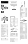
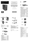
illustrated parts map
convertible minitower
The only warranties for HP products ansd services are set
forth in the express warranty statements accompanying such
products and services. Nothing herein should be construed
as constituting an additional warranty. HP shall not be liable
for technical or editorial errors or omissions contained
herein.
Product of the United States
February 2004
Miscellaneous Parts
Document Number
358328-001
1
Front I/O device
336446-001
2
Speaker
326776-001
3
PCI latch kit
339808-001
4
Hood sensor
267529-001
5
Solenoid lock with cable
336442-001
*
5.25” Bay bezel blank
335937-001
*
Diskette drive bay bezel blank
356687-001
*#
Heatsink with thermal grease and alcohol pad (see
reverse side)
333866-001
*
Chassis fan
330457-001
*
Mouse, 2-Button, PS/2 with scroll wheel
323614-001
*
Mouse, 2-Button, USB, optical with scroll wheel
323617-001
*
Mouse, 2-Button, wireless with scroll wheel
323616-001
*
Mouse, 2-Button, USB, with scroll wheel
323615-001
*
Rubber foot (4 ea. round, 4 ea. oval))
336445-001
*
Drive Key, 16 MB, carbon
324780-001
*
Drive Key, 64 MB, carbon
331465-001
*
Drive Key, 128 MB, carbon
331466-001
*
Drive Key, 128 MB, carbonite
349988-001
*
Nobel security lock without cable
335808-001
*
Nobel security lock with cable
335809-001
*
Return kit with buns
337910-001
*
Real-time-clock battery
153099-001
*
Port control cover
340400-001
*
PCI extender card tray
335817-001
*Not shown
#See back side for more information
Cables
System Unit
1
2
3
4
Front bezel assembly with sub panel, 5.25” bezel
blank, and diskette drive bezel
356593-001
Computer access panel
336444-001
Chassis assembly
Power supply, PFC
not spared
1
IDE cable, 15.25”, two device (108950-047)
336448-001
2
Power switch/LED cable with switch holder
336447-001
3
Diskette drive cable (143218-006)
333875-001
4
IDE cable, 12.5”, two device (108950-046)
333876-001
*
SATA Hard drive cable, use in standard hard drive
position
346141-001
*
SATA Hard drive cable, use in 5 1/4” drive bay only
346144-001
*#
DVI graphics cable
285380-001
*#
VGA graphics cable
285379-001
*#
DVI-VGA graphics adapter
202997-001
*
CD-ROM Audio cable (387527-001)
149806-001
*
Antenna cable for 332963-001 and 333864-001
333365-001
*
Flying serial port assembly kit
341899-001
308615-001
*Not shown
#Use with 322892-001, 322893-001, 274623-001, and 274622-001
Mass Storage Devices (not illustrated)
40 GB\5400 RPM Hard drive
236921-001
80 GB\5400 RPM Hard drive
292208-001
40 GB\7200 RPM Hard drive
286692-001
Miscellaneous screw kit
80 GB\7200 RPM Hard drive
250185-001
M3 x 5mm, hitop (263585-001) 4 ea
160 GB\7200 RPM Hard drive
325306-001
#6-32 x .250, hitop (262508-001) 8 ea
250 GB\7200 RPM Hard drive
344058-001
#6-32 x .250, pan head (101517-037) 3 ea
80 GB SATA Hard drive
345713-001
#6-32 x .312, hitop (262508-002) 4 ea
160 GB SATA Hard drive
345712-001
#6-19 x .312, pan head (101346-068) 2 ea
Diskette drive with mounting screws
333505-001
#6-19 x .315, T15 head (331310-001) 2 ea
48X CD-ROM drive with mounting screws
326773-001
48X/24X/48X CD-RW Drive
325308-001
48X/32X/48X CD-RW Drive
346788-001
Miscellaneous Screw Kit (not illustrated)
337237-001
Easy Access Keyboards (not illustrated)
Standard and Optional Boards
1
PCI extender card
252609-001
2
System board with alcohol pad and thermal grease
323091-001
Memory Modules
*
128 MB/400 MHz FSB
335697-001
*
256 MB/400 MHz FSB
335698-001
*
512 MB/400 MHz FSB
335699-001
*
1.0 GB/400 MHZ FSB
335700-001
*
128 MB/333 MHz FSB
314795-001
*
256 MB/333 MHz FSB
314793-001
*
512 MB/333 MHz FSB
314796-001
*
1.0 GB/333 MHZ FSB
314794-001
Intel Processors with alcohol pad and thermal grease
*
Celeron 2.0 GHz processor
309578-001
*
Celeron 2.2 GHz processor
321723-001
*
Celeron 2.3 GHz processor
335136-001
*
Celeron 2.4 GHz processor
351495-001
*
Celeron 2.5 GHz processor
344056-001
*
Celeron 2.6 GHz processor
344057-001
*
Pentium 2.4 GHz processor
288689-001
*
Pentium 2.53 GHz processor
333485-001
*
Pentium 2.66 GHz processor
305579-001
*
Pentium 2.8 GHz processor
305051-001
*
Pentium 3.0 GHz processor
315637-001
*
Pentium 2.4 GHz processor with Hyperthreading
335812-001
*
Pentium 2.6 GHz processor with Hyperthreading
333863-001
48X/24X/48X +16X DVD/CD-RW Drive
325309-001
PS/2 keyboard for PRC
323686-AA1
4X DVD+R/RW Drive
325317-001
Wireless keyboard for PRC
323745-AA1
16/40X DVD- ROM Drive
325313-001
USB keyboard for PRC
324636-AA1
Zip 250 Drive with mounting bracket
333504-001
USB keyboard with SmartCard for PRC
323746-AA1
Zip 250 Drive without mounting bracket
326772-001
*
Pentium 2.8 GHz processor with Hyperthreading
333864-001
Zip 750 Drive with mounting bracket
344060-001
*
Pentium 3.0 GHz processor with Hyperthreading
333865-001
Zip 750 Drive without mounting bracket
344059-001
*
Pentium 3.2 GHz processor with Hyperthreading
335813-001
PC MCIA Drive bay reader
331589-001
Other Cards
MultiBay drive adapter
335805-001
*
TPM security module
320163-001
24X/10X/24X/8X CD-RW/DVD-ROM MultiBay
drive
325312-001
*
Broadcom Gigabit NIC
321793-001
24X/24X/24X/8X CD-RW/DVD-ROM MultiBay
drive
346789-001
*
Intel Gigabit NIC
314901-001
*
Wireless LAN PCI Adapter , 11 channel (802.11)
332963-001
24X CD-ROM MultiBay drive
325314-001
*
Wireless LAN PCI Adapter , 13 channel (802.11)
333364-001
24/10/24X CD-RW MultiBay drive
325315-001
*
nVidia GeForce2 MX400, 32 M, ATX bkt
309492-001
8X/24X DVD-ROM MultiBay drive
325316-001
*
nVidia GeForce4 MX440, 64 M, ATX bkt
322891-001
*
nVidia MX400 64 MB, ATX BRACKET
335816-001
*
nVidia Quadro4 400 NVS, 64M, ATX bkt
274623-001
*
nVidia Quadro4 200 NVS, 32 M, ATX bkt
274622-001
*
nVidia Quadro4 100 NVS, 64 M, ATX bkt
322893-001
*
nVidia Quadro4 100 NVS, PCI, 64 M, ATX bkt
322892-001
*
DVI ADD 4-layer card
325833-001
*Not shown
Keyboard Diagnostic LEDs, PS/2 Keyboards O nly
LED
Color
LED Activity
State/Message
Num, Caps,
Scroll Lock
Green
On (Rising Tone)
ROM reflashed successfully
Num Lock
Green
On
ROMPaq diskette not present, is bad, or drive
not ready.*
Caps Lock
Green
On
Enter password.
Num, Caps,
Scroll Lock
Green
Blink On in sequence, one at a
time - N, C, SL
Keyboard locked in network mode
* Insert valid ROMPaq diskette in drive A. Turn power switch off, then on to reflash ROM. If ROM flash is successful, all
three keyboard LEDs will light up, and you will hear a rising tone series of beeps. Remove diskette and turn power off,
then on to restart the computer. For more information about flashing the ROM, refer to the Troubleshooting guide.
Clearing CMOS*
The computer's configuration (CMOS) may occasionally be corrupted. If it is, it is necessary to clear the CMOS
memory using switch SW50.
To clear and reset the configuration, perform the following procedure:
1. Prepare the computer for disassembly.
Ä
System Board Connectors and Jumpers (position of some untitled components may vary in location)
Secondary IDE
2.
3.
4.
5.
CAUTION: The power cord must be disconnected from the power source before pushing the Clear CMOS
Button (NOTE: All LEDs on the board should be OFF). Failure to do so may damage the system board
Remove the access panel.
Press the CMOS button located on the system board and keep it depressed for 5 seconds.
Replace the access panel.
Turn the computer on and run F10 Computer Setup (Setup-utility) to reconfigure the system.
E49
Password jumper
P21
J20
PCI slot 1
P23
Front audio/USB
J21
PCI slot 2
P27
Miulti Bay
*When the CMOS button is pushed or the jumper is removed, both the power-on password and the setup password
become invalid because both are stored in the configuration memory. You will need to reset the passwords.
J22
PCI slot 3
P29
SCSI LED
Disabling or Clearing the Power-On and Setup Passwords*
J30
PCI slot extender
P30
Primary Serial ATA (SATA) Port
J40
AGP slot
P31
Secondary Serial ATA (SATA) Port
P1
Main power (20 pin)
P54
Serial Port “B”
P3
CPU regulator power (4 pin)
P70
CPU fan
P5
Front panel
P124
Hood lock
P6
Internal chassis speaker
P125
Hood sensor
P7
CD audio in
SW50
CMOS button
P8
Chassis fan
XBT1
Battery
P10
Diskette drive
XMM1
Memory socket
P11
Aux audio in
XMM2
Memory socket
P14
Boot block
XMM3
Memory socket
P16
Power supply fan control
XMM4
Memory socket
P20
Primary IDE
XU100
Security
1.
2.
3.
4.
5.
6.
7.
8.
Turn off the computer and any external devices, and disconnect the power cord from the power outlet.
Remove the access panel.
Locate the header and jumper labeled E49.
Remove the jumper from pins 1 and 2. Place the jumper over pin 2 only, in order to avoid losing it.
Replace the access panel.
Plug in the computer and turn on power. Allow the operating system to start.
NOTE: Placing the jumper on pin 2 clears the current passwords and disables the password features.
To re-enable the password features, repeat steps 1-3, then replace the jumper on pins 1 and 2.
Repeat steps 5-6, then establish new passwords.
Refer to the Computer Setup (F10 Setup) instructions to establish new passwords.
*When the CMOS button is pushed or the jumper is removed, both the power-on password and the setup password
become invalid because both are stored in the configuration memory. You will need to reset the passwords.
Computer Setup (F10) Utility Features (not all features may be available)
File
System Information
About
Set Time and date
Save to Diskette
Restore From Diskette
Set defaults and Exit
Ignore Changes and Exit
Save Changes and Exit
Storage
Device Configuration
Options
IDE DPS Self-Test
Controller Order
SCSI Narrow Termination
Boot Order
Security
Setup Password
Power-On Password
Password Options
Smart Cover
Smart Sensor
DriveLock
Master Boot Record Security
Save Master Boot Record
Restore Master Boot Record
Device Security
Network Service Boot
System IDs
Advanced
Power-On Options
Onboard devices
PCI Devices
Bus Options
Devise Options
PCI VGA Configuration
Note: See Computer Setup (F10) Utility Guide on the Documentation Library CD.
Interchangeable Heatsinks
PCI Extender Card Connectors and Jumpers
J23
PCI slot 4
J24
PCI slot 5
P30
Male expansion plug
System Hardware Interrupts
IRQ
System Function
IRQ
System Function
0
Timer Interrupt
8
Real-Time Clock
1
Keyboard
9
Unused
2
Interrupt Controller Cascade
10
Unused, available for PCI
3
Serial Port (COM B)
11
Unused, available for PCI
4
Serial Port (COM A)
12
Mouse
5
Unused, available for PCI
13
Coprocessor
6
Diskette Drive
14
Primary ATA (IDE) Controller
7
Parallel Port (LPT 1)
15
Secondary ATA (IDE) Controller
Computer Diagnostic LEDs (on front of computer)
LED
Color
LED Activity
State/Message
Power
Green
On
(S0) Computer on
Power
Green
1 blink every 2 seconds
(S1) Suspend Mode
Power
Green
1 blink every 2 seconds
(S3) Suspend to RAM
Power
Green
Off
(S4) Suspend to Disk (if applicable)
Power
Clear
Off
(S5) Computer off
Power
Red
1 blink followed by 2-second
pause - Repeat
Power Supply failure
Power
Red*
2 blinks 1 second apart
CPU thermal shutdown
Power
Red*
3 blinks 1 second apart
CPU not installed
Power
Red*
4 blinks 1 second apart
Power supply overload ( crow bar)
Power
Red*
5 blinks 1 second apart
No memory
Power
Red*
6 blinks 1 second apart
No graphics
Power
Red*
7 blinks 1 second apart
System board failure (detected prior to video)
Power
Red*
8 blinks 1 second apart
Invalid ROM
Hard Drive
Green
Blinking
Hard drive activity
*Blinking codes are repeated after a 2 second pause.
Heat Sink Removal