1
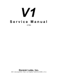
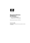
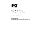
HP Compaq Business Desktop
dx2100 Microtower Models
© 2005 Hewlett-Packard Development Company, L.P.
HP and the HP logo are trademarks of Hewlett-Packard
Development Company, L.P.
Illustrated Parts Map
Intel and Celeron are US registered trademarks of Intel
Corporation. All other product names mentioned herein
may be trademarks of their respective companies.
Celeron and Pentium Processors
HP shall not be liable for technical or editorial errors or
omissions contained herein. The information in this
document is provided “as is” without warranty of any kind
and is subject to change without notice. The warranties for
HP products are set forth in the express limited warranty
statements accompanying such products. Nothing herein
should be construed as constituting an additional
warranty.
Standard and Optional Boards
Memory modules
1st Edition, December 2005
Document Part Number 404567-001
1
256 MB, PC2-4200, CL4
393392-001
*
512 MB, PC2-4200, CL4
393393-001
*
1 GB, PC2-4200, CL4
393394-001
2
System board with alcohol pad and thermal grease
405059-001
Intel Celeron D Processors with alcohol pad and thermal grease
*
2.66 GHz #331, 256 K cache, 533 MHz FSB
391940-001
*
2.8 GHz #336, 256 K cache, 533 MHz FSB
391941-001
*
2.93 GHz #341, 256 K cache, 533 MHz FSB
405692-001
*
3.06 GHz, #346, 256 K cache, 533 MHz FSB
405693-001
*
3.2 GHz #351, 256 K cache, 533 MHz FSB
382503-001
Intel Pentium Processors with alcohol pad and thermal grease
*
2.8 GHz #521 1M cache, 800 MHz FSB
394643-001
*
3.0 GHz #531 1M cache, 800 MHz FSB
394642-001
*
3.0 GHz #630 2M cache, 800 MHz FSB
392273-001
*
3.2 GHz #640 2M cache, 800 MHz FSB
384786-001
*
3.4 GHz #650 2M cache, 800 MHz FSB
384787-001
Other boards
*
Nvidia Quadro NVS 280 graphics w/64 MB, PCI
398686-001
*
Wireless LAN PCI adapter, 802.11
391866-001
*
Wireless LAN PCI adapter, 802.11, NA only
391866-002
*
NIC, PCI-e
393626-001
* Not shown
System Unit
Cables
1
Front bezel without bezel blank
405065-001
2
Access panel
405062-001
3
Chassis
not spared
1
SATA HDD cable, 13” lg (381868-001)
4
Power supply, non-PFC
405060-001
2
Optical disk drive cable, 2 devices (384944-003)
* Not shown
Miscellaneous cable kit, includes:
405066-001
3
Diskette drive data cable (385981-002)
*
USB cable with bracket and mounting screws
405064-001
*
Power switch with switch mounting bracket
405063-001
Miscellaneous Parts
*Not shown
Keyboards (not illustrated)
*
U.S.
Miscellaneous parts kit, includes:
*
3.5” drive adapter to fit 5.25” bay
*
diskette drive front bezel
*
Power/LED switch holder
*
LED holder
*
#6-32 x .312 hitop screw with serrations (4 ea)
(192308-002)
*
#6-32 x .250 hitop screw with serrations (4 ea)
(192308-001)
*
Taptite hitop screw (114399-069)
*
Taptite #6-32 hitop screw with serrations (4 ea)
(192308-003)
382925-001
*Not shown
Mass Storage Devices
1
Diskette drive, 3.5-inch
392415-001
2
48X CD-ROM drive
397130-001
*
52X CD-ROM drive
333969-005
*
48X/32/X48X CD-RW drive
395272-001
*
48X/32X/48X+16X CD-RW/DVD-ROM drive
405425-001
*
16/48X DVD ROM Drive
405761-001
*
16X DVD +/- RW
405760-001
3
40-GB\7200 RM SATA hard drive, 1.5 Gb/s
409232-001
*
80-GB\7200 RPM SATA hard drive, 3.0 Gb/s
391945-001
*
160-GB\7200 RPM SATA hard drive, 3.0 Gb/s
391741-001
*
250-GB\7200 RPM SATA hard drive, 3.0 Gb/s
391937-001
*Not shown
405652-001
*
M3 x 5 mm Taptite hitop screw (247348-001)
*
5.25” Bezel blank
1
Chassis fan with mounting screws
405061-001
2
Heatsink with alcohol pad and factory-applied thermal grease
408575-001
*
Mouse, PS2, scroll type
390937-001
*
Mouse, USB, scroll type
390939-001
*
Mouse, optical
390938-001
*
Battery, real-time clock
153099-001
3
Internal speaker
405653-001
*
Foot (4 ea)
370708-001
*Not shown
Clearing CMOS
The computer's configuration (CMOS) may occasionally be corrupted. If it is, it is necessary to clear the CMOS
memory using by performing the following procedure:
Ä
1.
2.
3.
4.
5.
6.
7.
8.
CAUTION: The power cord must be disconnected from the power source before changing the jumper
setting. (NOTE: All LEDs on the board should be OFF). Failure to do so may damage the system board
Turn off the computer and any external devices, then disconnect the power cord from the power outlet.
Remove the access panel.
Locate jumper CMOS and move the jumper from pins 2-3 to pins 1-2.
Leave the jumper on pins 1-2 for 5 seconds.
Move the jumper back to pins 2-3.
Replace the access panel.
Connect the power cord to the power outlet.
Turn on the computer, allow it to start.
Diagnostic LEDs
System Board Connectors and Jumpers (position of some untitled components may vary in location)
CMOS
Clear CMOS
P7
Front side USB
CN8
CD audio
PCI1
PCI Expansion slot1
CR2
Health LED
PCI2
PCI Expansion slot 2
FDD1
Diskette drive
SATA 0
Primary SATA drive
J32
PCI Express x1
SATA 1
Secondary SATA drive
J94
Main power switch/LED
U3
Microprocessor
P1
Chassis fan
XBT 2
Real-time-clock battery
P10
Primary IDE
XMM1
DIMM 1
P11
Speaker
XMM2
DIMM 2
P1
CPU fan
XMM3
DIMM 3
P3
Main power
XMM4
DIMM 4
P4
CPU power (4-pin)
Jumper
Setting
Notes
Normal
2-3
Default
Clear
1-2
leave on for 5 seconds
Color
LED Activity
State/Message
Power
Green
On
Computer on
Power
Green
1 blink every 2 seconds
(S1) Normal Suspend Mode
Power
Green
1 blink every 2 seconds
(S3) Suspend to RAM
Power
Clear
Off
(S5) Computer off
Power
Green
Glows for 3 seconds followed by CPU thermal shutdown
a 1 second pause.
Power
Green
1 blink every second for 5
seconds, then 2 second pause.
5 beeps.
No memory installed or improperly installed
(pre-video memory error)
Power
Green
1 blink every second for 6
seconds, then 2 second pause.
6 beeps.
Graphics card error (pre-video graphics error)
None
None
No LED but rapidly inclining
beeps
Incorrect system password.
None
None
No LED but rapidly declining
beeps
Correct system password.
Hard Drive
Green
Blinking
Hard drive activity
Computer Setup (F10) Utility Features (not all features may be available)
CMOS
Status
LED
System Hardware Interrupts
IRQ
System Function
IRQ
System Function
0
Timer Interrupt
8
Real-Time Clock
1
Keyboard
9
Unused
2
Interrupt Controller Cascade
10
Unused, available for PCI
3
Serial Port (COM B)
11
Unused, available for PCI
4
Serial Port (COM A)
12
Mouse
5
Unused, available for PCI
13
Coprocessor
6
Diskette Drive
14
Primary ATA (IDE) Controller
7
Parallel Port (LPT 1)
15
Secondary ATA (IDE) Controller
System
Information
Product Name
Processor Type
Processor speed
CPU ID
Cache Size
Memory Size
System ROM
Integrated MAC Address
System Serial Number
Asset Tag Number
Standard CMOS
Features
Set Date
Set Time
PATA Channel 0 Master, PATA Channel 0 Slave
SATA Controller
PATA IDE Mode
SATA Port
PATA Channel 0 Master, PATA Channel 1 Master
FDC Controller
Drive A
Halt On
POST Delay
Advanced BIOS
Features
Device Boot Disabling
Removable Device Priority
Hard Disk Boot Priority
Optical Drive Boot Priority
Network Boot Priority
F9 Boot Menu Display
Quick Power On Self Test
First, Second, and Third Boot Devices
HDD SMART Drive Capability
Boot Up NumLock Status
Security Option
Hyperthreading Technology
APIC Mode
MPS Version Control for OS
OS Select for DRAM > 64MB
BIOS Write Protection
Advanced
Chipset Features
PCI Express Root Port Func
On-Chip Frame Buffer Size (VGA Setting)
DVMT Mode (VGA Setting)
DVMT Memory Size (VGA Setting)
Init Detect PCI Clk (VGA Setting)
Auto Detect PCI Clk (VGA Setting)
Spread Spectrum (VGA Setting)
Integrated
Peripherals
USB Controller
USB Legacy Support
Onboard Audio
Onboard LAN
Onboard LAN Boot ROM
Onboard Serial Port 1
Onboard Parallel Port
Parallel Port Mode
ECP Mode Use DMA
Power
Management
Setup
ACPI Function
ACPI Suspend type
Soft OFF by Power Button
Power ON after Power Fail
MODEM use IRQ
Resume by PME
Wake on Device S5
Resume by Alarm
Date (of Month) Alarm
Time (hh:mm:ss)
PnP/PCI
Configuration
Reset Configuration Data
Resources Controlled By
IRQ Resources
Maximum Payload Size
PC Health Status
CPU Temperature
CPU Fan Speed
System Fan Speed
SYS Fan Fault Detect
Load Optimized
Defaults
Set Supervisor
Password
Set User
Password
Save & Exit Setup
Exit Without
Saving
Note: See Computer Setup (F10) Utility Guide on the Documentation Library CD.