1
HP FlexFabric 5900CP Solutions
Configuration Guide
Abstract
This document describes HP FlexFabric 5900CP switch usage in converged Ethernet and storage network configurations. It
provides information about switch features and storage configurations, including the device support.
HP Part Number: 5697-3386
Published: November 2014
Edition: 2
© Copyright 2014, Hewlett-Packard Development Company, L.P.
Confidential computer software. Valid license from HP required for possession, use or copying. Consistent with FAR 12.211 and 12.212, Commercial
Computer Software, Computer Software Documentation, and Technical Data for Commercial Items are licensed to the U.S. Government under
vendor's standard commercial license.
The information contained herein is subject to change without notice. The only warranties for HP products and services are set forth in the express
warranty statements accompanying such products and services. Nothing herein should be construed as constituting an additional warranty. HP shall
not be liable for technical or editorial errors or omissions contained herein.
Contents
1 HP FlexFabric 5900CP switch overview.........................................................4
Features and benefits................................................................................................................4
HP FlexFabric 5900CP network architectures................................................................................5
2 Port types and switch modes........................................................................7
Port types................................................................................................................................7
Switch modes...........................................................................................................................7
3
4
5
6
Storage use-cases.......................................................................................9
IRF usage with storage..............................................................................20
c-Class BladeSystem interconnects...............................................................24
HP FlexFabric 5900CP Storage Network Support.........................................25
HP
HP
HP
HP
FlexFabric
FlexFabric
FlexFabric
FlexFabric
5900CP Operating System Support with Storage....................................................25
5900CP CNA/HBA Support................................................................................25
NPV Switch Support............................................................................................26
HP Storage System Support..................................................................................27
7 Software and Firmware update process.......................................................28
8 Management Software..............................................................................29
Using the CLI.........................................................................................................................29
IMC Management software......................................................................................................30
A HP FlexFabric 5900CP system architecture considerations..............................31
B Support information..................................................................................34
C HP FlexFabric 5900CP switch configuration file............................................36
Glossary....................................................................................................43
Contents
3
1 HP FlexFabric 5900CP switch overview
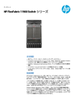
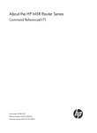
The HP FlexFabric 5900CP switch is a multipurpose converged L2/L3 switch with 48 converged
ports and four 40 GbE QSFP+ ports. This switch provides seamless integration of lossless 10GbE
networks into server-edge environments and core environments through FCoE, DCB, Fibre Channel,
and many other Ethernet network protocols. It is a full featured switch and a software license is
not required. When coupled with the HP StoreFabric converged optical transceiver, it provides
wire-once capability for 10GbE/FCoE and 8 Gb or 4 Gb Fibre Channel.
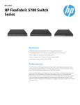
Figure 1 HP FlexFabric 5900CP front (port) and rear (power) view
The 5900 switch family is supported for use as standard Ethernet switches in HP Networking
Ethernet networks and as DCB Ethernet switches for converged environments with Ethernet/FCoE
and iSCSI connectivity. It provides native Fibre Channel and FCoE full-featured connectivity and
can be used as a gateway to other HP Fibre Channel switch series fabrics using NPV (N_Port
virtulization).
The HP 5900 family series members can be common members of an IRF (Intelligent Resilient
Framework) domain to simplify management by combining multiple physical switches into one
virtual switch. An IRF fabric appears as one node or virtual switch and is accessible as a single IP
address on the network. You can use this IP address to log in at any member device to manage
all the members of the IRF domain.
Features and benefits
The HP FlexFabric 5900CP switch provides the following features:
4
•
Ethernet/FCoE support on 10GbE converged ports and 40GbE ports
•
Fibre Channel 8Gb/4Gb/2Gb support on any of the 48 converged ports
•
DCB/FCoE-FCF/NPV/TRILL/IPv6 support (QCN ready)
•
Forty-eight converged ports that can use a single transceiver which supports 10GbE/FCoE or
8Gb/4Gb Fibre Channel
•
FCoE/FC NPV gateway support
•
Dual-hop support with Virtual Connect blade switches and the HP 6125-XLG
•
Multi-hop support using FCoE VE_Port (7 hops) or Fibre Channel E_Port (3 hops) ISLs (inter-switch
links)
•
5900 Series IRF support (up to nine switches per domain with Ethernet, two switches per
domain with storage)
•
iSCSI support
•
Front-to-back or back-to-front airflow
•
Comware OS version 7.1
HP FlexFabric 5900CP switch overview
•
No additional feature licenses. The following four switch modes are available:
◦
Standard—Configurable DCB switch
◦
FCF—FC/FCoE initiator; target; FlexFabric SAN switch; F, VF, VE, and E port connectivity
(4K zones); FSPF
◦
NPV—Gateway for FC/FCoE multi-vendor connectivity
◦
Transit—FIP-snooping DCB aggregation switch
•
1.28 Tb/s switching capacity
•
952.32 Million PPS throughput, integrated 9 MB packet buffer
•
10GbE cut-through latency < 1.5 µs (64Byte packets)
•
CLI and iMC/VAN/VFM (Intelligent Management Center) fabric management
•
HP IIIAS (Intelligent Infrastructure Analyzer Software) support
•
L2/L3, IPv4/IPv6 dual stack, TRILL, VEPA
•
Cloud and SDN ready (OpenFlow 1.3.1 support)
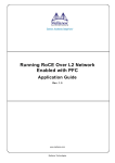
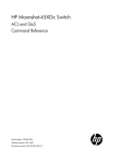
Figure 2 (page 5) describes the major components and the ports of the HP FlexFabric 5900CP
switch. The front view shows the 48 converged ports and the four 40GbE ports.
The switch supports two pluggable fan trays and two AC power supplies for redundancy. Two
options are available for fan trays, front-to-back airflow or back-to-front airflow.
Figure 2 HP FlexFabric 5900CP components and ports
HP FlexFabric 5900CP network architectures
The HP FlexFabric 5900CP switch can be utilized in the following environments:
•
A traditional Ethernet network switch for Ethernet data
•
A converged network switch in environments that support Ethernet and FCoE for storage data
•
A native Fibre Channel fabric switch for storage data
In a converged environment, the HP FlexFabric 5900CP switch is typically configured as a ToR
switch connecting to a LAN and a SAN.
LAN connectivity is made through any of the 48 converged ports configured as 10GbE ports or
the 40GbE ports for a total of up to 64 10GbE ports.
SAN connectivity is made through any of the 48 converged ports configured as 10GbE/FCoE
ports or configured as 8/4/2 Gb Fibre Channel ports. When configured as FCoE ports, the
converged ports support device connectivity (VF_Port) or switch connectivity using inter-switch links
HP FlexFabric 5900CP network architectures
5
(ISLs) (VE_Ports) to other 5900CP or 5900AF switches, the 6125XLG, or via NPV (VNP_Ports) to
other HP FCoE switches that support NPIV. When configured as Fibre Channel ports, the converged
ports support device connectivity (F_Port) or switch connectivity via inter-switch links (ISLs) (E_Ports)
to other 5900CP switches, or via NPV (NP_Ports) to other HP Fibre Channel switches that support
NPIV.
6
HP FlexFabric 5900CP switch overview
2 Port types and switch modes
To support LAN and SAN environments, the HP FlexFabric 5900CP switch utilizes multiple port
types and switch modes.
Port types
The HP FlexFabric 5900CP switch supports multiple port types. Table 1 (page 7) lists the port
types supported.
Table 1 Supported HP FlexFabric 5900CP port types
Ethernet Port Types
• Access/Tagged-trunk 10GbE/40GbE ports used for Ethernet data
FCoE Port Types
• VF_Port: Virtual F_Port (FCoE switch to FCoE target/initiator)
• VE_Port: Virtual E_Port (FCoE switch to FCoE switch)
• VNP_Port: FCoE NPV switch port (FCoE switch to FCoE switch as a proxy)
FC Port Types
• F_Port: Fabric port (switch to FC target/initiator)
• E_Port: Expansion port (switch to switch ISL)
• NP_Port: NPV switch port (FC switch to FC switch as a proxy)
Switch modes
The HP FlexFabric 5900CP switch supports four operating modes. Standard mode is the default
mode. FCF, NPV, and Transit modes are advanced modes.
1. Standard (Non-FCoE) Mode—When a switch operates in this mode, it is a standard DCB/
Ethernet switch and does not provide any FCoE/FC capabilities.
Ethernet connectivity
•
2.
HP FlexFabric 5900CP 10GbE/40GbE ports for Ethernet data (access/tagged-trunk).
FCF (Fibre Channel Forwarder)—When a switch operates in this mode, it is called as an FCF
switch. In this mode, the following HP FlexFabric 5900CP converged port connections are
available:
Ethernet connectivity
•
HP FlexFabric 5900CP 10GbE/40GbE ports for Ethernet data (access/tagged-trunk).
Fibre Channel
•
HP FlexFabric 5900CP F_Port to an N_Port on a node.
•
HP FlexFabric 5900CP (NPIV) F_Port to an NP_Port on an NPV switch or module.
•
HP FlexFabric 5900CP E_Port to an E_Port on another HP FlexFabric 5900CP FCF switch.
Port types
7
FCoE
•
HP FlexFabric 5900CP VF_Port to a VN_Port on a node.
•
HP FlexFabric 5900CP (NPIV) VF_Port to a VNP_Port on an NPV switch or module.
•
HP FlexFabric 5900CP VE_Port to the VE_Port on another HP FlexFabric 5900CP, HP
5900AF, HP 6125XLG, or other FCF capable HP Networking switch or switches.
If the primary mode of the HP FlexFabric 5900CP switch is set to FCF, the converged ports
can be set to F_Port or E_Port, but cannot be set to NP_Port. For FCoE, the ports can be set
to VF_Port or VE_Port, but cannot be set to VNP_Port.
3.
NPV/Gateway Mode—When a switch operates in this mode, it is called as an NPV (N_Port
Virtualizer) switch. In this mode, the following HP FlexFabric 5900CP converged port
connections are available:
Ethernet connectivity
•
HP FlexFabric 5900CP 10GbE/40GbE ports for Ethernet data (access/tagged-trunk).
Fibre Channel
•
HP FlexFabric 5900CP F_Port to an N_Port on a node.
•
HP FlexFabric 5900CP NP_Port to an F_Port on an FCF (NPIV) switch.
•
HP FlexFabric 5900CP (NPIV) F_Port to an NP_Port on an NPV switch or module.
FCoE
•
HP FlexFabric 5900CP VF_Port to a VN_Port on a node.
•
HP FlexFabric 5900CP VNP_Port to a VF_Port on an FCF (NPIV) switch.
•
HP FlexFabric 5900CP (NPIV) VF_Port to a VNP_Port on an NPV switch or module.
If the primary mode of the HP FlexFabric 5900CP switch is set to NPV, the converged ports
can be set to F_Port or NP_Port, but cannot be set to E_Port. For FCoE, the ports can be set
to VF_Port or VNP_Port, but cannot be set to VE_Port.
4.
Transit Mode—When a switch operates in this mode, it is called as a Transit switch. A switch
operating in this mode can restrict its Ethernet interface only to receiving traffic from an eNode
or FCF switch. This is achieved by configuring the interface to operate in eNode mode or FCF
mode. Fibre Channel is not supported in this mode. When a switch is configured in Transit
mode, it always enables FIP snooping. VF_Port traffic is allowed, however, VE_Port traffic is
blocked.
NOTE: After changing to any one of the advanced modes and saving the configuration,
you must reboot the switch, then implement the port configurations.
<HP>system-working-mode {advance standard}
<HP>fcoe-mode {fcf npv transit}
[confirmation]
[mode changed]
<HP>save
<HP>reboot
8
Port types and switch modes
3 Storage use-cases
The HP FlexFabric 5900CP switch supports several converged Ethernet/FCoE and Fibre Channel
storage configurations. To simplify understanding and implementation of these configurations, a
set of use-case topology designs are defined. The use-cases describe recommended ways to use
the HP FlexFabric 5900CP switch, switch modes, and port types in different server-storage
deployment scenarios. Some of the use-cases show multiple types of connectivity within the same
configuration. This is meant to show the different connection options available. Your design might
use one or more of these options, but not necessarily all as shown.
HP recommends that all storage configurations implement dual-redundant fabrics for high availability.
All HP FlexFabric 5900CP switch use-cases for storage described here implement dual-redundant
fabrics for high availability.
NOTE: The IRF feature of the HP FlexFabric 5900CP switch can be implemented in dual-redundant
fabric designs with storage, but has implications that must be considered. For more information
about using IRF in a storage configuration, see “IRF usage with storage” (page 20)
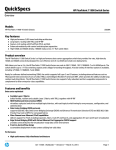
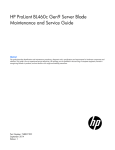
Figure 3 (page 9) provides three major, single-tier use-case scenarios, each describing a different
implementation based on the hardware being utilized for servers and storage. All use-cases show
a single layer or single tier of HP FlexFabric 5900CP switches, also referred as East-West fabric
topology, with variations for use-case 2 and use-case 3. Use-case 2 shows dual-hop on the server
side and use-case 3 shows additional fabric connectivity on the storage side to other HP Fibre
Channel/FCoE switch series fabrics via 5900CP NPV gateway mode.
Figure 11 (page 16) through Figure 14 (page 19) describe HP FlexFabric 5900CP multi-hop or
cascaded switch use-cases. For all multi-hop configurations using the HP FlexFabric 5900CP in
FCF mode, HP supports up to seven hops for FCoE, and up to three hops for Fibre Channel. For
NPV mode, HP supports a total of seven hops between any two devices in the 5900CP fabric and
the legacy Fibre Channel fabric connected via NPIV.
Figure 3 HP FlexFabric 5900CP major, single-tier use-case scenarios
Table 2 (page 10) describes the HP FlexFabric 5900CP use-cases. The items listed in the variant
column are links to the figures which describe the variant connectivity options in detail.
9
Table 2 HP FlexFabric 5900CP use-cases
Major SAN Fabric
Use-Case
Variant
5900CP
Server Connect Storage Connect Switch Mode
#1 Single-Tier
Fabric, Rack
Servers
1A: Rack Server, FCoE Storage
Rack/CNA
1B: Rack Server, FC Storage
Rack/CNA/HBA Native FC
#2 Single-Tier
Fabric, Blade
System
2A: BladeSystem Dual-hop, FCoE Storage
Blade/VC
Native FCoE
2B: BladeSystem FC/FCoE, FC Storage
Blade/FC
Native FC
#3 Single-Tier
Fabric, NPV
Gateway
3A: Rack Server, FC NPV Gateway, FC Storage Rack/CNA/HBA FC via B/C/H
FC Switch
3B: BladeSystem, FC NPV Gateway, FC Storage Blade/VC
Native FCoE
FCF
3C: Rack/BladeSystem, FCoE NPV Gateway
Rack/CNA/HBA FC/FCoE via
Blade/VC/FC Cisco Nexus
55xx FCoE
Switch
#4 Multi-hop
Fabric, Rack
Servers
4A: Rack Server, FCoE Storage
Rack/CNA
4B: Rack Server, FC Storage
Rack/CNA/HBA Native FC
#5 Multi-hop
Fabric, Blade
Servers
5A: BladeSystem, FCoE Storage
Blade/VC
Native FCoE
5B: BladeSystem FC/FCoE, FC Storage
Blade/FC
Native FC
#6 Multi-hop
Fabric, NPV
Gateway
For all HP FlexFabric 5900CP NPV mode
Rack/CNA/HBA FC via B/C/H
configurations, HP supports a maximum of seven
Blade/VC/FC FC Switch
hops between any two devices in the 5900CP
fabric and the legacy Fibre Channel fabric
Rack/CNA/HBA FC/FCoE via
connected via NPV/NPIV.
Blade/VC/FC Cisco Nexus
55xx FCoE
Switch
Storage Fabric
IRF
Configurations
Applies to all Use-Cases above
NPV
Gateway
Native FCoE
FCF
Rack/CNA/HBA Native FCoE,
Blade/VC/FC FC
NPV
Gateway
FCF, NPV
NOTE: For enhanced availability during incompatible Comware updates, multi-hop configurations
should avoid configuring IRF on the last hop 5900 switches when these switches are connected
to storage devices.
10
Storage use-cases
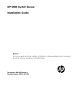
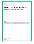
Figure 4 HP FlexFabric 5900CP FCF Use-Case 1A
FCoE Storage
LAN
IRF
VN_Port
VN_Port
Expand
switches
horizontally
as required
VF_Port
IRF*
VF_Port
5900CP FCF
FCoE
Converged Ethernet/FCoE
Native Ethernet
FCoE
IRF* between 5900CP’s
(optional)
Server/CNA
5900CP1A
Figure 5 HP FlexFabric 5900CP FCF Use-Case 1B
FC Storage
LAN
IRF
N_Port
N_Port
Expand
switches
horizontally
as required
F_Port
IRF*
F_Port
5900CP FCF
FCoE/FC
Converged Ethernet/FCoE
Native FC
Native Ethernet
IRF* between 5900CP’s
(optional)
Server/CNA
Server/HBA
5900CP1b
11
Figure 6 HP FlexFabric 5900CP FCF Use-Case 2A
FCoE Storage
LAN
VN_Port
IRF
VN_Port
Expand
switches
horizontally
as required
VF_Port
VF_Port
IRF*
5900CP FCF
FCoE
Converged Ethernet/FCoE
Native Ethernet
FCoE
IRF* between 5900CP’s
or 6125XLGs (optional)
Blade Server/CNA
Blade Server/CNA
5900CP2A
Converged Ethernet/FCoE server connection options (Use-case 2A):
12
•
Virtual Connect 20/40 F8
•
Virtual Connect Flex - 10/10D, FCoE
•
6125XLG, FCoE (NPV)
•
Virtual Connect FlexFabric 10Gb/24–Port (8Gb FC, 10GbE FCoE/Ethernet)
Storage use-cases
Figure 7 HP FlexFabric 5900CP FCF Use-Case 2B
FC Storage
LAN
IRF
N_Port
N_Port
Expand
switches
horizontally
as required
F_Port
F_Port
IRF*
5900CP FCF
FCoE/FC
Converged Ethernet/FCoE
Native FC
Native Ethernet
IRF* between 5900CP’s
or 6125XLGs (optional)
Blade Server/CNA
Blade Server/CNA or HBA
5900CP2b
Converged or Native FC server connection options (Use-case 2B):
•
Virtual Connect 20/40 F8
•
Virtual Connect Flex - 10/10D, FCoE
•
Virtual Connect FlexFabric 10Gb/24–Port (8Gb FC, -10GbE FCoE/VC)
•
Virtual Connect 8Gb 24-Port Fibre Channel Module for c-Class BladeSystem (Brocade)
•
Virtual Connect 8Gb 20-port Fibre Channel Module for c-Class BladeSystem
•
Blade Switch: HP 6125XLG, Ethernet/FCoE (6125XLG in NPV mode)
•
Blade Switch: HP 8/24c SAN Switch (Brocade, Access Gateway mode)
•
Blade Switch: MDS 8Gb 24-port Switch (Cisco, NPV/NPIV enabled)
13
Figure 8 HP FlexFabric 5900CP NPV Use-Case 3A
FC Storage
LAN
N_Port
IRF
N_Port
Fabric-A
Fabric-B
F_Port
Expand
switches
horizontally
as required
F_Port
IRF*
NP_Port
Fabric-A, Fabric-B
HP 5900CP, HP Brocade,
Cisco, or QLogic FC Switches
NP_Port
5900CP NPV
FCoE/FC
Converged Ethernet/FCoE
Native FC
Native Ethernet
IRF* between 5900CP’s
(optional)
Server/HBA
Server/CNA
5900CP3A
Figure 9 HP FlexFabric 5900CP NPV Use-Case 3B
FC Storage
LAN
N_Port
IRF
N_Port
Fabric-A
Expand
switches
horizontally
as required
Fabric-B
F_Port
F_Port
NP_Port
Fabric-A, Fabric-B
HP 5900CP, HP Brocade,
Cisco, or QLogic FC Switches
NP_Port
IRF*
5900CP NPV
FCoE/FC
Converged Ethernet/FCoE
Native FC
Native Ethernet
IRF* between 5900CP’s
or 6125XLGs (optional)
Blade Server/CNA or HBA
14
Storage use-cases
Blade Server/CNA
5900CP3B
Converged or Native FC server connection options (Use-cases 3A and 3B):
•
Virtual Connect 20/40 F8
•
Virtual Connect Flex - 10/10D, FCoE
•
Virtual Connect FlexFabric 10Gb/24–Port (8Gb FC, -10GbE FCoE/VC)
•
Virtual Connect 8Gb 24-Port Fibre Channel Module for c-Class BladeSystem (Brocade)
•
Virtual Connect 8Gb 20-port Fibre Channel Module for c-Class BladeSystem
•
Blade Switch: HP 6125XLG, Ethernet/FCoE (6125XLG in NPV mode)
•
Blade Switch: HP 8/24c SAN Switch (Brocade, Access Gateway mode)
•
Blade Switch: MDS 8Gb 24-port Switch (Cisco, NPV/NPIV enabled)
Figure 10 HP FlexFabric 5900CP NPV Use-Case 3C
FC Storage
LAN
N_Port
Cisco Nexus
55xx FCoE/FC
N_Port
IRF
Fabric-A
VF_Port
Expand
switches
horizontally
as required
VNP_Port
Fabric-B
Cisco Nexus
55xx FCoE/FC
VF_Port
VNP_Port
IRF*
5900CP NPV
FCoE
Converged Ethernet/FCoE
Native FC
Native Ethernet
FCoE
IRF* between 5900CP’s
or 6125XLGs (optional)
Blade Server/CNA
Blade Server/CNA
5900CP3D
Converged Ethernet/FCoE server connection options (Use-case 3C):
•
Virtual Connect Flex - 10/10D, FCoE
•
6125XLG, FCoE (6125XLG in NPV mode)
•
Virtual Connect FlexFabric 10Gb/24–Port (8Gb FC, 10GbE FCoE/Ethernet)
15
Figure 11 HP FlexFabric 5900CP FCF Maximum FCoE Hop Count Use-Case 4A
FCoE
Storage
VN_Port
8
Expand switches
horizontally as
required.
LAN
VN_Port
VF_Port
7
6
5
4
VF_Port
3
VE _Ports
8
2
7
VE _Ports
6
1
5
VE_Port
4
3
IRF*
2
VE_Port
Rack Server/CNA
Expand switches vertically
as required, up to 8 switches
(7 hops) total: each hop
optionally an IRF pair
1
Rack Server/CNA
Converged Ethernet/FCoE
Native Ethernet
FCoE
IRF* between hop pairs
of 5900CP’s
(Optional, Ethernet
connection only)
5900CP4A
16
Storage use-cases
Figure 12 HP FlexFabric 5900CP FCF Maximum FC Hop Count Use-Case 4B
Expand switches
horizontally as
required.
LAN
FC
Storage
N_Port
4 F_Port
N_Port
3
2
E_Ports
1
F_Port
E_Port
E_Ports
4
3
IRF*
2
E_Port
Rack Server/CNA
Expand switches vertically as
required, up to 4 switches
(3 hops) total; each hop
optionally an IRF pair
1
5900CP FCF
Native FC
Rack Server/HBA
Converged Ethernet/FCoE
Native FC
Native Ethernet
FCoE
IRF* between hop pairs
of 5900CP’s
(Optional, Ethernet
connection only)
5900CP4B
17
Figure 13 HP FlexFabric 5900CP FCF Maximum FCoE Hop Count Use-Case 5A
FCoE
Storage
VN_Port
8
Expand switches
horizontally as
required.
LAN
VN_Port
VF_Port
7
6
5
4
VF_Port
VE _Ports
3
8
VE _Ports
VE_Ports
1
7
6
2
5
VE_Port
4
3
IRF*
VE_Port
2
Blade Server/CNA
1
5900CP FCF
Native FCoE
Expand switches vertically as
required, up to 8 switches
(7 hops) total, including
6125XLG or VC Flex-10/10D.
Each hop pair optionally
IRF, except VC-Flex modules.
Blade Server/CNA
Converged Ethernet/FCoE
Native Ethernet
FCoE
IRF* between hop pairs
of 5900CPs or 6125XLGs
(Optional, Ethernet
connection only)
5900CP5A
Converged Ethernet/FCoE server connection options (Use-case 5A):
18
•
Virtual Connect 20/40 F8
•
Virtual Connect Flex - 10/10D, FCoE
•
6125XLG, FCoE (NPV or FCF)
Storage use-cases
Figure 14 HP FlexFabric 5900CP FCF Maximum FC Hop Count Use-Case 5B
FC
Storage
Expand switches
horizontally as
required.
4 F_Port
LAN
N_Port
N_Port
3
2
E_Ports
F_Port
1
E_Port
E_Ports
4
3
IRF*
2
E_Port
Blade Server/CNA
Expand switches vertically
as required, up to 4 switches
(3 hops) total; each hop
optionally an IRF pair
1
5900CP FCF
Native FC
Blade Server/CNA/HBA
Converged Ethernet/FCoE
Native FC
Native Ethernet
FCoE
IRF* between 5900CP’s
(Optional, Ethernet
connection only)
5900CP5B
Converged or Native FC server connection options (Use-case 5B):
•
Virtual Connect 20/40 F8
•
Virtual Connect Flex - 10/10D, FCoE
•
Virtual Connect FlexFabric 10Gb/24–Port (8Gb FC, -10GbE FCoE/VC)
•
Virtual Connect 8Gb 24-Port Fibre Channel Module for c-Class BladeSystem (Brocade)
•
Virtual Connect 8Gb 20-port Fibre Channel Module for c-Class BladeSystem
•
Blade Switch: HP 6125XLG, Ethernet/FCoE (6125XLG in NPV mode or FCF mode)
•
Blade Switch: HP 8/24c SAN Switch (Brocade, Access Gateway mode)
•
Blade Switch: MDS 8Gb 24-port Switch (Cisco, NPV/NPIV enabled)
19
4 IRF usage with storage
The HP FlexFabric 5900CP switch supports IRF for use with Ethernet and storage networks. For
Ethernet networks, you can configure up to nine HP FlexFabric 5900CP switches in a single IRF
domain. For storage networks, including FCoE, you can configure up to two switches per fabric
in an IRF domain. When using IRF, NIC teaming is supported and is utilized for LAN traffic.
For more information about IRF, see the HP 5900 switch series documentation available on the
HP Networking website at http://h17007.www1.hp.com/us/en/networking/products/switches/
HP_5900_Switch_Series/index.aspx#.UwuBMU2A1aQ.
For Ethernet/FCoE/FC storage network environments, the following HP FlexFabric 5900CP
storage-IRF deployment scenarios are supported:
1. Dual-redundant fabric SAN with no IRF— Traditional Fibre Channel high availability
no-single-point-of-failure (NSPOF) configuration. See Figure 15 (page 20).
•
Provides physically separate redundant fabrics with failover capabilities for high availability
with storage.
Considerations
•
Highly available, NSPOF configuration
•
Firmware updates are considered partially disruptive, requiring fabric failover. See
“Software and Firmware update process” (page 28)
Figure 15 Dual-redundant storage fabric configuration, no IRF
FC Storage
Fabric-A
Server/HBA
2.
20
5900CP
Switches
Fabric-B
Server/CNA
5900CP4B
Dual-redundant fabric SAN with 2-switch IRF for Ethernet—Implemented with two HP FlexFabric
5900CP switches configured in an IRF domain across both the fabrics, with one switch from
each fabric. See Figure 16 (page 21).
•
Provides logically separate redundant fabrics with failover capabilities for high availability
with storage
•
Requires two VSANs to prevent storage traffic across the IRF link
IRF usage with storage
•
Must be specific on device placement to allow desired access such as CNA to storage
•
Allows Ethernet usage of the IRF links
Considerations
•
Not considered a NSPOF configuration, IRF spans virtual fabrics
•
Firmware updates are considered disruptive to both VSANs, requiring scheduled downtime.
Figure 16 Dual-redundant storage fabric configuration, 2-Switch IRF for Ethernet-only
FC and FCoE Storage
Fabric-AB
“Virtual Switch”
VSAN1
Server/CNA
IRF
VSAN2
Server/HBA
5900CP5B
3.
Dual-redundant fabric SAN with 4-switch IRF for Ethernet—Implemented with two HP FlexFabric
5900CP switches in each fabric configured in two IRF domains for high availability and
NSPOF. See Figure 17 (page 22).
•
Provides physically separate redundant fabrics with failover capabilities for high availability
with storage
•
Requires four VSANs to prevent storage traffic across the IRF link
•
Requires two CNAs per server or two HBAs per server
•
Must be specific on device placement to allow desired access
•
Allows Ethernet usage of the IRF links
Considerations
•
Highly available, NSPOF configuration
•
Firmware updates are considered partially disruptive, requiring fabric failover. See
“Software and Firmware update process” (page 28)
21
Figure 17 Dual-redundant storage fabric configuration, 4-Switch IRF for Ethernet-only
FC and FCoE Storage
Fabric-B
“Virtual Switch”
Fabric-A
“Virtual Switch”
VSAN1
VSAN2
VSAN3
Server/CNA
4.
5900CP7C
Dual-redundant storage fabric configuration with two stacked switches
in IRF domains—Implemented with two HP FlexFabric 5900CP switches in each fabric
configured in two IRF domains for high availability and NSPOF. See Figure 18 (page 23).
•
Avoid irf-port congestion by using multiple 40G connections
•
Only one VSAN per IRF domain required
•
No specific device connectivity to maintain NSPOF
•
When storage is connected to switches utilizing IRF, add the following command to the
configuration file: fspf graceful-restart
•
Firmware updates are considered partially disruptive, requiring fabric failover. See
“Software and Firmware update process” (page 28)
•
This configuration leverages IRF as a stacking interconnect with one VSAN per IRF domain
and includes FCoE QOS configuration of stacked irf-ports. Enable FCoE priority 3
priority-flow-control on irf-ports.
Examples:
irf-port 1/1
port group interface FortyGigE1/0/49
priority-flow-control auto
priority-flow-control no-drop dot1p3
irf-port 2/1
port group interface FortyGigE2/0/49
interface FortyGigE2/0/49
priority-flow-control auto
priority-flow-control no-drop dot1p3
22
Server/HBA
VSAN4
IRF usage with storage
irf-port 1/2
port group interface FortyGigE1/0/50
interface FortyGigE1/0/50
priority-flow-control auto
priority-flow-control no-drop dot1p 3
irf-port 2/2
port group interface FortyGigE2/0/50
interface FortyGigE2/0/50
priority-flow-control auto
priority-flow-control no-drop dot1p 3
Figure 18 Dual-redundant storage fabric configuration, two stacked switches in IRF domains
FC and FCoE
Storage
Fabric-A
“Virtual Switch”
VSAN 2
VSAN 2
Server/CNA
Fabric-B
“Virtual Switch”
VSAN 3
Server/HBA
VSAN 3
5900CP7D
23
5 c-Class BladeSystem interconnects
The HP FlexFabric 5900CP switch supports connectivity to multiple HP server interconnect options
including Virtual Connect modules/switches and BladeSystem switches. See Table 1 (page 7).
For Virtual Connect modules, Flex-10/10D and FlexFabric 10 Gb/24-port, connectivity is through
FIP Snooping to the HP FlexFabric 5900CP switch in FCF mode.
For BladeSystem switches, connectivity is configured based on the BladeSystem switch used. For
an HP 6125XLG dual-hop configuration, set HP 6125XLG mode to NPV and the HP FlexFabric
5900CP switch mode to FCF or NPV. For multi-hop, set 6125XLG mode to FCF and 5900CP switch
to FCF mode.
For the HP 8/24c SAN Switch (Brocade), set the switch in Access Gateway mode. For the MDS
8Gb 24-port Switch (Cisco), enable the switch for NPV/NPIV to connect to the HP FlexFabric
5900CP switch in FCF mode using NPIV.
Table 3 (page 24) describes BladeSystem interconnect support for the HP FlexFabric 5900CP
switch. For more information about current HP FlexFabric 5900CP storage support, see the HP
SPOCK website at http://www.hp.com/storage/spock. You must sign up for an HP Passport to
enable access.
Table 3 HP FlexFabric 5900CP BladeSystem Interconnect Support
24
Virtual Connect Modules/Blade Switches
HP FlexFabric 5900CP Mode
Virtual Connect 20/40 F8
• FCF
Virtual Connect Flex-10/10D, FCoE (FIP Snooping)
• FCF
Virtual Connect FlexFabric 10Gb/24-Port (8Gb FC,
10GbE FCoE/VC FIP Snooping)
• FCF
Virtual Connect 8Gb 24-Port Fibre Channel Module for
c-Class BladeSystem (Brocade)
• FCF
Virtual Connect 8Gb 20-port Fibre Channel Module for
c-Class BladeSystem
• FCF
Blade Switch: HP 6125XLG, Ethernet/FCoE (6125XLG
in NPV mode or Transit or FCF mode)
• FCF, NPV, or Transit
Blade Switch: HP 8/24c SAN Switch (Brocade, Access
Gateway mode)
• FCF
Blade Switch: MDS 8Gb 24-port Switch (Cisco, NPV/
NPIV enabled)
• FCF
c-Class BladeSystem interconnects
6 HP FlexFabric 5900CP Storage Network Support
The following section describes the operating system and the hardware support for the HP FlexFabric
5900CP switch when used in a storage network configuration. For more information about current
HP FlexFabric 5900CP storage support, see the HP SPOCK website at http://www.hp.com/
storage/spock. You must sign up for an HP Passport to enable access.
HP FlexFabric 5900CP Operating System Support with Storage
Following operating systems are supported:
•
Windows 2012, 2012 R2 x64, Hyper-V
•
Windows 2008 SP2 x86/x64, Hyper-V
•
Windows 2008 R2 SP1 x86/x64, Hyper-V
•
RHEL 5.0, 6.3, 6.4, 6.5, x86/x64
•
SUSE Linux SLES 10 SP3, SP4, 11 SP2 x86/x64
•
VMware ESX 5.1 U2, ESX 5.5
HP FlexFabric 5900CP CNA/HBA Support
HP FlexFabric 5900CP CNA Support
•
HP StoreFabric CN1200E 10Gb Converged Network Adapter
•
HP StoreFabric CN1100R Dual Port Converged Network Adapter
•
HP CN1100E
•
HP CN1000E
•
HP CN1000Q
•
HP FlexFabric 20Gb 2-port 650FLB Adapter
•
HP FlexFabric 20Gb 2-port 650M Adapter
•
HP FlexFabric 20Gb 2-port 630FLB Adapter
•
HP FlexFabric 20Gb 2-port 630M Adapter
•
HP FlexFabric 10Gb 2-port 556FLR-SFP+ Adapter
•
HP FlexFabric 10Gb 2P 554FLR-SFP+ Adapter
•
HP FlexFabric 10Gb 2P 554M Adapter
•
HP FlexFabric 10Gb 2P 554FLB Adapter
•
HP BLc NC553m DP FlexFabric Adapter Opt and NC553i
•
HP BLc NC551m DP FlexFabric Adapter Opt and NC551i
•
HP FlexFabric 10Gb 2-port 534FLB Adapter
•
HP FlexFabric 10Gb 2-port 534FLR-SFP+ Adapter
•
HP FlexFabric 10Gb 2-port 534M Adapter
HP FlexFabric 5900CP HBA Support
•
HP StoreFabric SN1000Q 16Gb 1-port and 2-port PCIe Fibre Channel Host Bus Adapter
•
HP StoreFabric SN1000E 16Gb 1-port and 2-port PCIe Fibre Channel Host Bus Adapter
HP FlexFabric 5900CP Operating System Support with Storage
25
•
HP QMH2572 8Gb FC HBA
•
HP BLc QLogic QMH2562 8Gb FC HBA Opt
•
HP 82Q 8Gb Dual Port PCI-e FC HBA
•
HP PCIe 2-port 8Gb FC SR (QLogic) HBA
•
HP 81Q PCI-e FC HBA
•
HP PCIe 1-port 8Gb FC SR (QLogic) HBA
•
HP LPe1205A 8Gb FC HBA Opt
•
HP BLc Emulex LPe1205 8Gb FC HBA Opt
•
82E 8Gb Dual-port PCI-e FC HBA
•
HP 81E 8Gb SP PCI-e FC HBA
HP FlexFabric NPV Switch Support
Converged Network Switches
Connectivity to the following FCoE switches via HP FlexFabric 5900CP NPV mode is supported:
•
Cisco Nexus 5548UP/5596UP FCoE Converged Network Switch
•
Cisco Nexus 5010/5020 FCoE Converged Network Switch
•
Cisco MDS 9000 10-Gbps 8-Port FCoE Module
NOTE: Merged FCoE fabric interoperability (VE_Port) is supported only between multiple HP
FlexFabric 5900CP switches or HP FlexFabric 5900CP switches and HP 5900AF or HP 6125XLG
(FCF mode) switches. Merged Fibre Channel fabric interoperability (E_Port) is supported only
between HP FlexFabric 5900CP switches.
Fibre Channel Switches
Connectivity to the following Fibre Channel switches via HP FlexFabric 5900CP NPV mode is
supported:
•
HP StoreFabric SN6500B 16Gb 96/96 FC Switch, 96/48 FC Switch, SN6000B, SN3000B
•
StorageWorks 8/80, 8/24, 8/8 SAN Switch
•
StorageWorks EVA 4400 embedded switch
•
StorageWorks 8Gb DC04 SAN Director, 8Gb DC SAN Backbone Director, StorageWorks
8/40 SAN Switch
•
SN8000B SAN Director
•
Brocade 8Gb SAN Switch for HP BladeSystem c-Class
•
C-series HP StorageWorks SN6000C Fabric Switch (Cisco MDS 9148)
•
Cisco MDS 8Gb Fabric Switch for BladeSystem c-Class
•
H-series SN6000 Fibre Channel Switch, 8/20q Fibre Channel Switch
For the latest supported switch software versions, see the B-series, C-series and H-series switch
documentation.
NOTE: Merged fabric interoperability (E_Port) is not supported between HP FlexFabric 5900CP
switch and other HP Fibre Channel switches (B-series, C-series, or H-series).
26
HP FlexFabric 5900CP Storage Network Support
HP FlexFabric HP Storage System Support
HP FlexFabric HP Storage System Support:
•
3PAR StoreServ 10400/10800 FCoE/Fibre Channel/iSCSI
•
3PAR 7200/7400/7450 FCoE/Fibre Channel/iSCSI
•
3PAR F-Class (F200/F400) Fibre Channel
•
P6300/P6350/P6500/ P6550 FCoE/Fibre Channel/iSCSI
•
P9500 FCoE/Fibre Channel
•
P2000 G3 Fibre Channel
•
MSA 2040 (G4) Fibre Channel
•
EVA 4400 (with or without embedded switch) Fibre Channel
•
EVA 6400/8400 Fibre Channel
•
StoreVirtual P4330 and 4730 FC
HP FlexFabric HP Storage System Support
27
7 Software and Firmware update process
Firmware Update Process – Non ISSU
The non-ISSU firmware update process is disruptive if you have implemented a single SAN fabric
or a dual SAN fabric using logically separate fabrics. See “IRF usage with storage” (page 20). If
you have implemented a dual-redundant NSPOF SAN, the firmware process is considered partially
disruptive, requiring fabric failover. To update the firmware using non-ISSU procedure:
1. Ensure that the latest firmware is obtained via hp.com
2. Use the dir command to verify that all IRF member devices have sufficient storage space for
the upgrade images, and use the delete or delete/unreserved command to delete
unused files. Use the reset recycle-bin command to permanently delete files from flash.
3. Use the ftp client on the switch to download and the boot-loader command to update flash
for each slot.
a. <HP> ftp <IP address> then login to the server.
b. <HP> bin
c. <HP> get <firmware filename.ipe>
d. <HP> boot-loader file flash:/<firmware file name> slot 1 main
The following message appears:
This command will set the main startup software images. Continue?
[Y/N]:.
Enter: Y and proceed.
NOTE:
e.
In an IRF configuration, step d must be executed for all slots.
<HP> save
NOTE: A save must be completed before a reboot to ensure that the current configuration
is not lost unless the user wants to revert back to the saved configuration in the .cfg file.
The following message appears:
The current configuration will be written to the device. Are you
sure? [Y/N]:
Enter: Y and proceed.
Please input the the filename (*/cfg) [flash:/config87.cfg]
(To leave the existing filename unchanged, press the enter key):
flash:/config87.cfg exists, overwrite?[Y/N]:
Enter: Y and proceed.
Validating file. Please wait...
Saved the current configuration to mainboard device successfully.
f.
<HP> reboot
NOTE:
g.
The reboot command will reboot all switches in the IRF domain.
Verify that the device is running the correct software.
<Sysname> display version
28
Software and Firmware update process
8 Management Software
The primary management interface for the HP FlexFabric 5900CP switch is through the Command
Line Interface (CLI). To access the CLI, see “Using the CLI” (page 29). All the management commands
necessary for HP FlexFabric 5900CP switch are available through the CLI. Management support
for HP FlexFabric 5900CP switch is also provided with HP IMC (Intelligent Management Center)
software. There are three levels of support with IMC – no license is required for level 1, a license
is required for level 2 and for the FCoE plug-in module. For more information on IMC features, see
“IMC Management software” (page 30).
Using the CLI
When accessing the switch for the first time, you must use a console cable to connect a console
terminal, such as a PC, to the console port on the switch.
Using the console cable provided with the switch, first plug the DB-9 female connector of the console
cable to the serial port of the PC, and then connect the RJ-45 connector to the console port of the
switch.
To configure and manage the switch, you must run a terminal emulator program on the console
terminal.
The required terminal settings are:
•
Bits per second: 9,600
•
Data bits: 8
•
Parity: None
•
Stop bits: 1
•
Flow control: None
•
Emulation: VT100
By default, login through the console port is enabled and the user role network-admin is assigned.
A username and password is not required for login. After login, configure password or scheme
authentication mode to improve device security.
To prevent illegal access to the CLI and control user behaviors, configure login authentication,
assign user roles, configure command authorization and command accounting, and use ACLs to
filter unauthorized login.
By default, you can log in to the CLI only through the console port. To facilitate device management,
log in to the device through the console port and configure other login methods such as Telnet and
SSH.
To log in through the Telnet:
1. Enable the Telnet server function.
2. Assign an IP address to a Layer 3 interface and make sure that the interface and the telnet
client can establish a connection between them.
3. Configure an authentication mode for VTY login users.
4. By default, password authentication is used but no password is configured.
5. Assign a user role to VTY login users. The default role assigned is network-operator.
To log in through the SSH:
1. Enable the SSH server function and configure SSH attributes.
2. Assign an IP address to a Layer 3 interface and make sure the that interface and the SSH
client can establish a connection between them.
Using the CLI
29
3.
4.
Configure scheme authentication for VTY login users. The default authentication scheme is
password authentication.
Assign a user role to VTY login users. The default role assigned is network-operator.
IMC Management software
IMC management software provides following features:
30
•
Level 1–Discovery: Basic standalone IMC support (event logs), no license required
•
Level 2/3–Access device, read/update configurations: Virtual Application Network (VAN)
Fabric Management (VFM), license required
•
Optional plug-in module (FCoE add-on license)
•
VAN Fabric topology–Physical topology of networks (LAN/SAN)
•
DC management–Logical group of networks, servers, and storage devices
•
SAN configuration–Fabric/FCoE management, zone configuration, zone sets, devices
•
LAN configuration–Trill configuration, SPB network, device management, VLANs, AC lists,
EVI config
•
Statistics–VLAN, I-SID, ECT
•
Interface–SNMP/MIBs
Management Software
A HP FlexFabric 5900CP system architecture considerations
Parameter name/type
Parameter value
Remarks
Fabric logins per FCF
255
E-port utilizes one Login, reduce the
number by one for each e-port
connected switch. FSPF for hop by hop
routing, static route support, up to 255
routes. The maximum number of static
routes allowed in a VSAN is 256.
VSAN's per switch
16
Virtual SANs with overlapping address
space up to 16. The maximum number
of VSANs, including the default VSAN,
allowed on a switch is 16.
VFC and FC interfaces per switch
512
Virtual FC interfaces up to 512 per
switch.
Number of zones per switch
4000
Each soft zone can have as many
members as necessary; recommend
utilization of I-T zones. You can
configure a maximum of 4000 zones
for all VSANs on a switch.
Number of Hard Zones per VSAN
255
Limited by port entry rules, assuming I-T
members per zone.
Zone Alias names
4000
You can configure a maximum of 4000
zone aliases for all VSANs on a switch.
Zonesets per switch
128
You can configure a maximum of 128
zone sets for all VSANs on a switch.
Zone member Alias names
4000
You can configure a maximum of 4000
zone member alias names
Number of NPIV WWNs per NP port 127
NPIV support with up to 127 VN_Ports
per VF_port.
Number of MAC addresses bound to 127
VFCs per VF_port
NPIV support with up to 127 VN_Ports
per VF_port.
Number of FC port Transmit BB credits 15
Default value set during link
initialization.
Domain IDs or maximum number of
switches per SAN
239
Similar to an FC switch, each FCF
switch is assigned a domain ID. Each
FC SAN supports a maximum number
of 239 domain IDs, so an FC SAN
cannot have more than 239 switches.
IRF members
9
Ethernet only configuration.
irf link-delay interval
INTEGER <0-10000>
The IRF fabric might run other protocols
, for example, CFD, VRRP, FCoE, and
OSPF, that have a shorter protocol
packet lifetime than the delay interval.
For stable protocol running, make sure
the delay interval is shorter than the
maximum lifetime of these protocol
packets. You can adjust either the IRF
link down report delay or the maximum
lifetime of the protocol packets.
Specify the time interval in ms for the
link layer to report a link-down event.
Non-overlapping VSANs per IRF
domain member switch
8
Storage configuration recommends one
VSAN per member switch and no
common VSANs for member switches
31
Parameter name/type
Parameter value
Remarks
to avoid storage traffic flow over IRF
links.
Set the maximum number of Selected link-aggregation selected-port
ports for the aggregation group.
maximum number 32
By default, the maximum number of
selected ports for an aggregation group
is 32.
Set the minimum number of Selected
ports for the aggregation group.
By default, the minimum number of
selected ports for the aggregation
group is not specified.
link-aggregation selected-port
minimum number
10GbE LR SFP+ lossless (PFC) working 10 km - single-mode fiber
distance
HP X130 SFP+ LC LR Transceiver
JD094B 10GbE lossless connectivity on
single-mode fiber
10GbE SR SFP+ lossless (PFC) working 300 m - OM3
distance
HP X130 SFP+ LC SR transceiver
JD092B 10GbE lossless 300m
connectivity on multi-mode fiber
10GbE ER SFP+ lossless (PFC) working 40 km - single-mode fiber
distance when extended buffering is
configured
HP X130 SFP+ LC ER transceiver
JG234A 10GbE 40 km on single-mode
fiber
10GbE Limited SR SFP+ lossless (PFC) 125 m - OM4
working distance
H6Z42A SFP+ 50um OM4 multi-mode
fiber
8 Gbps FC SFP+ BB credit working
distance
150 m - OM3 190M - OM4
AJ718A SFP+ multi-mode fiber
4 Gbps FC SFP+ BB credit working
distance
380 m - OM3 400m - OM4
AJ718A SFP+ multi-mode fiber
2 Gbps FC SFP+ BB credit working
distance
500 m - OM3
AJ718A SFP+ multi-mode fiber
8/4/2Gbps FC SFP+ working
distance
10 km - single-mode fiber
AW584A SFP+ Link lengths up to 10
km at 8.5/4.25/2.125 GBd with
single mode fiber (15 BB credits limited)
8Gbps FC SFP+ BB credit working
distance
190 m - OM4
H6Z42A SFP+ 50um OM4
4Gbps FC SFP+ BB credit working
distance
400 m - OM4
H6Z42A SFP+ 50um OM4
40GbE SR QSFP+ lossless (PFC)
working distance
150 m - OM4
HP X140 40G QSFP+ MPO SR4
transceiver JG325B
40GbE LR4 QSFP+lossless (PFC)
working distance
10 km - single-mode fiber
HP X140 40G QSFP+ LC LR4 SM
CWDM transceiver JG661A
40GbE copper QSFP+ PFC working
distance
5m
HP X240 40G QSFP+ 5m direct attach
copper cable JG328A
10GbE copper QSFP+ PFC working
distance
7m
HP X240 10G SFP+ 7m direct attach
copper cable JC784C
FSPF graceful restart
120 s typical
The default setting is 120 seconds. FSPF
GR (Graceful Restart) enables nonstop
forwarding of traffic by backing up
FSPF configuration information during
a protocol restart, for example, the FSPF
process restart triggered by the process
command, or active/standby
switchover.
100 m - OM3
Fabric Device Management Interface 8
(FDMI) function, FDMI objects per port
32
HP FlexFabric 5900CP system architecture considerations
An HBA object can have a maximum
of eight port objects.
Parameter name/type
Parameter value
Remarks
Upper limit of concurrent logins using access-limit max-user-number 16
the same user name
recommended
By default, the number of concurrent
logins is not limited for the local user.
This command takes effect only when
local accounting is configured for the
local user. It does not apply to FTP,
SFTP, or SCP users who do not support
accounting.
Configure password control attributes Depends on environment
for the local user.
Configure the maximum login attempts
and the action to take if there is a login
failure: password-control login-attempt
login-times [ exceed { lock | lock-time
time | unlock } ]
Enable broadcast suppression and set broadcast-suppression { ratio | pps
the broadcast suppression threshold. max-pps | kbps max-kbps }
By default, broadcast traffic is allowed
to pass through an interface.
Enable multicast suppression and set
the multicast suppression threshold.
multicast-suppression { ratio | pps
max-pps | kbps max-kbps }
By default, multicast traffic is allowed
to pass through an interface.
Enable unknown unicast suppression
and set the unknown unicast
suppression threshold.
unicast-suppression { ratio | pps
max-pps | kbps max-kbps }
By default, unknown unicast traffic is
allowed to pass through an interface.
Set the maximum number of lines to
be displayed on a screen.
screen-length screen-length
By default, a screen displays a
maximum of 24 lines. A value of 0
disables pausing between screens of
output.
Set the maximum number of concurrent aaa session-limit telnet max-sessions
Telnet users.
default=16
Changing this setting does not affect
online users. If the current number of
online Telnet users is equal to or greater
than the new setting, no additional
Telnet users can log in until online users
log out.
33
B Support information
The HP FlexFabric 5900CP switch provides various display capabilities. You can use the displays
to identify issues by viewing configurations, port status summaries, and more in-depth information
about each port.
By default, the switch updates a logfile once a day. You can generate a g-zipped tar file using
the display diagnostic CLI command and export this file for review. Two files are required for
support:
•
the configuration file—startup.cfg
•
logfile—logfile.log
These text files are stored in flash:/startup.cfg and flash:/logfile/logfile.log.
The name of the configuration file can be different if you have changed it. You must have a backup
copy of the configuration file. Ensure that the current configuration is saved to a .cfg file before
requesting support.
NOTE:
Generate a support file as follows:
[5900cp]display diag
Save or display diagnostic information
(Y=save, N=display)? [Y/N]:y
Input the file name
(*.tar.gz)[flash:/ diag.tar.gz]:
Displayed information not included in the diag file, which can be separately logged:
display fc login
display fcs data
display fc na database
display fc domain-list
display vsan port-member
Following are some useful CLI commands:
•
display current (HotKey <Ctrl-G>)
•
display version
•
display interface brief
•
display interface
•
display zone status
•
display fc login
•
display fcs database
•
display vsan nnn port-member
•
display npv login
•
display counters inbound interface
•
display counters outbound interface
•
display link-aggregation verbose
These CLI commands help you to view the information and identify the issue quickly.
34
Support information
In the following examples, two configuration files are named after the switch number. The
config87.cfg file is the primary file representing how the switch is presently configured.
<HP>dir
Directory of flash:
0 -rw8215552 Mar 10 2014 15:51:10 5900_5920-cmw710-boot-r2308p01.bin
1 -rw52940800 Mar 10 2014 15:53:08 5900_5920-cmw710-system-r2308p01.bin
2 -rw22736 Jul 23 2013 20:46:13 config87-npv.cfg
3 -rw32344 Mar 11 2014 23:19:59 config87.cfg
4 -rw223240 Mar 11 2014 23:19:59 config87.mdb
5 -rw169086 Mar 14 2014 15:27:27 diag.tar.gz
6 drw- Jan 01 2011 00:00:35 diagfile
7 -rw567 Jul 16 2013 22:33:41 dsakey
8 - drw- Feb 19 2014 18:02:53 fczone
9 -rw735 Oct 15 2013 09:26: 3 -rw32344 Mar 11 2014
23:19:59 config87.cfg 20
hostkey
10 -rw1795 Mar 11 2014 23:19:56 ifindex.dat
11 -rw0 Aug 14 2013 20:45:49 lauth.dat
12 drw- Jan 01 2011 00:00:36 license
13 drw- Jul 08 2013 23:09:01 logfile
14 -rw111321 Aug 08 2008 20:00:00 lsw152qf.vme
15 -rw916801 Aug 09 2013 14:04:55 lsws5820x11152_v1.26.btw
16 -rw591 Oct 15 2013 09:26:20 serverkey
17- drw- Aug 12 2013 17:43:59 versionInfo
524288 KB total (330800 KB free)
<HP>dir
Directory of flash:/logfile
0 -rw10483710 Mar 14 2014 15:36:30
524288 KB total (330800 KB free)
The flash:/startup.cfg or your
logfile.log
[HP]display logfile summary
Log file: Enabled
Log file size quota: 10 MB
Log file directory: flash:/logfile
Writing frequency: 24 hour 0 min 0 sec
[HP]display diagnostic
Save or display diagnostic information (Y=save, N=display)? [Y/N]:y
Please input the file name(*.tar.gz)[flash:/diag.tar.gz]:
The file already exists, overwrite it? [Y/N]:y
Diagnostic information is outputting to flash:/diag.tar.gz.
Please wait...
Save successfully.
35
C HP FlexFabric 5900CP switch configuration file
This appendix shows some sections from the HP FlexFabric 5900CP switch configuration file.
Use this as a guide for creating the configuration file for your specific implementation.
LLDP must be and STP should be enabled for FCoE functionality
#
lldp global enable
#
stp global enable
The switch must be in advance mode to operate FCoE/FC
functionality
system-working-mode advance
#
Setup Switch Mode [fcf, npv, transit]
fcoe-mode fcf
#For balanced two fabric multi-hop configurations use FSPF graceful restart
fspf graceful-restart
#
Define the vsan - valid vsan numbers 1-3839 maximum 16 per switch
Can set the domain ID as a static ID
Zoning information for the vsan is kept here.
To use persistent FCIDs define using wwn <your WWN> area-port-id
<4 digit hex of desired FCID>
vsan 100
domain-id static
rscn aggregation enable
wwn 21:00:2c:27:d7:53:f5:87 area-port-id 0001
zone-alias name Enc6S1P1
member pwwn 10:00:6c:3b:e5:a4:a2:71
zone-alias name P10K-FC-ports
member pwwn 20:52:00:02:ac:00:62:f6
member pwwn 21:52:00:02:ac:00:62:f6
zone name P10K-FC
member zone-alias Enc6S1P1
member zone-alias P10K-FC-ports
zoneset name 5900CP_vsan100
member P10K-FC
zoneset distribute full
36
HP FlexFabric 5900CP switch configuration file
zoneset activate name 5900CP_vsan100
#
#
vlan 1
#
vlan 1001
description ToLAN
#
There shall be an FCoE enabled VLAN associated with each vsan
configured regardless of port-type FC and Ethnernet/FCoE
vlan 4001
description ToSAN-A
fcoe enable vsan 100
#
Definition of the FCoE and other queues
qos map-table dot1p-lp
import 0 export 0
import 1 export 0
import 2 export 0
import 3 export 1
import 4 export 0
import 5 export 0
import 6 export 0
import 7 export 0
#
acl 4000 for FCoE - acl 3000 for iSCSI use
acl number 4000 name DCBX
rule 0 permit type 8906 ffff
rule 5 permit type 8914 ffff
#
#
acl number 3000
rule 0 permit tcp destination-port eq 3260
##################################################
#
Configure DCBx
traffic classifier DCBX operator or
if-match acl 4000
if-match acl 3000
#
traffic behavior DCBX
37
remark dot1p 3
#
qos policy DCBX
classifier DCBX behavior DCBX mode dcbx
#
Configure Console Connectivity
line class aux
user-role network-admin
#
line class vty
user-role network-operator
#
line aux 0 1
user-role network-admin
idle-timeout 0 0
#
line vty 0 15
authentication-mode scheme
user-role network-admin
user-role network-operator
# execute set authentication password simple <your_password> and it will put it in the config file
similar to below.
set authentication password hash $h$6$/YSmSK0b+l+RSYbX$OaP0ytCZcE8rWgKEx6nQw0rLML
3Mf0+O0g7UZAeh95kEejMhv6RecR4nT06+9LTYESUU ezfhzMchHYC8h4ACcA==
idle-timeout 0 0
#
#
#
LLDP management address - used for VC connectivity
Each management interface must be in its own subnet
interface Vlan-interface1
ip address 10.10.10.1 255.255.255.0
#
#
domain system
#
domain default enable system
#
#
user-group system
#
local-user admin class manage
38
HP FlexFabric 5900CP switch configuration file
execute password simple <your password> and it will put it in the
config file similar to below.
password hash
$h$6$im0rLRRRYOJHIwCY$zjEOgLLx7RF5dm5GDg5h4Fc
6zJGeVYkDomKh9VKVnqq3NCW9QmsrGAlOOPWZTy/EUu
tU0KLgW9HQismv1+PAOg==
Setup FTP/Telnet/SSH services
service-type ftp
service-type ssh telnet terminal
authorization-attribute user-role network-admin
authorization-attribute user-role network-operator
#
ftp server enable
#
#
This is the physical management port. Use YOUR IP address!
interface M-GigabitEthernet0/0/0
ip address 10.X.X.X 255.255.255.0
#
Settings for typical FCoE port
If setting up multiple ports simultaneously use the range command
as illustrated:
#
interface range Ten-GigabitEthernet 1/0/1 to Ten-GigabitEthernet 1/0/9
#
Configure a HYBRID port when using multiple untagged VLANS
#Use the description to help with defining what the link is used for
interface Ten-GigabitEthernet1/0/1
description R113-S01
port link-mode bridge
port link-type hybrid
#vlan numbers have to be what you have defined
port hybrid vlan 4001 tagged
port hybrid vlan 1 1001 untagged
port hybrid pvid vlan 1001
priority-flow-control auto
priority-flow-control no-drop dot1p 3
39
stp edged-port
lldp tlv-enable dot1-tlv dcbx
qos trust dot1p
qos wrr be group 1 byte-count 15
qos wrr af1 group 1 byte-count 15
qos wrr af2 group sp
qos wrr af3 group sp
qos wrr af4 group sp
qos wrr ef group sp
qos wrr cs6 group sp
qos wrr cs7 group sp
qos apply policy DCBX outbound
#
Standard FC interface - to change the ethernet port to FC use the
port-type fc command. Supported FC port modes [auto, e, f], auto
is the default mode.
#
interface Fc1/0/11
port access vsan 100
qos trust dot1p
NOTE: FC port speed default is AUTO and fill-word is idle-arbff. For 4Gbps and 2Gpbs, configure
fill-word to idle-idle.
############################################
Configure a Vfc to enable FCoE device login. Supported FCoE port
modes [f,e], f is the default mode, there is no auto mode. A ve port
must be configured using fc mode e.
interface Vfc1
fc mode f
port trunk vsan 100
bind interface Ten-GigabitEthernet1/0/1
#
MAC binding when devices coming from a FIP snooping or standard
DCB device
#
interface Vfc200
port trunk vsan 100
bind interface Bridge-Aggregation1 mac 6c3b-e5af-ad09
#
Setup a Vfc to uplink from NPV switch to FCF or NPV switch
#
interface vfc1000
40
HP FlexFabric 5900CP switch configuration file
fc mode np
port trunk vsan 100
bind interface FortyGigE 1/0/49
#
To create an aggregation group follow these steps:
1.
2.
3.
Create the link-aggregation interface.
a. interface Bridge-Aggregation X (where X is a number)
b. port link-type trunk
c. port trunk permit vlan 1 102 1001
d. link-aggregation mode dynamic
Associate each of the member ports.
a. interface Ten-GigabitEthernet 1/0/1
b. port link-aggregation group X
c. interface Ten-GigabitEthernet 1/0/2
d. port link-aggregation group X
Make final settings on the link-aggregation interface.
a. interface Bridge-Aggregation X
b. port link-type trunk
c. port trunk permit vlan 1 1001 4001 - use the vlans that were defined
interface Bridge-Aggregation1 description
port link-type trunk
port trunk permit vlan 1 4001
port trunk pvid vlan 1001
link-aggregation mode dynamic
#
interface Ten-GigabitEthernet 1/0/1
port link-mode bridge
port link-type trunk
port trunk permit vlan 1 1001 4001
port trunk pvid vlan 1001
priority-flow-control auto
priority-flow-control no-drop dot1p 3
lldp tlv-enable dot1-tlv dcbx
qos trust dot1p
qos wrr be group 1 byte-count 15
qos wrr af1 group 1 byte-count 15
qos wrr af2 group sp
qos wrr af3 group sp
qos wrr af4 group sp
qos wrr ef group sp
qos wrr cs6 group sp
qos wrr cs7 group sp
qos apply policy DCBX outbound
port link-aggregation group 1
#
41
interface Ten-GigabitEthernet 1/0/2
port link-mode bridge
port link-type trunk
port trunk permit vlan 1 1001 4001
port trunk pvid vlan 1001
priority-flow-control auto
priority-flow-control no-drop dot1p 3
lldp tlv-enable dot1-tlv dcbx
qos trust dot1p
qos wrr be group 1 byte-count 15
qos wrr af1 group 1 byte-count 15
qos wrr af2 group sp
qos wrr af3 group sp
qos wrr af4 group sp
qos wrr ef group sp
qos wrr cs6 group sp
qos wrr cs7 group sp
qos apply policy DCBX outbound
port link-aggregation group 1
#
42
HP FlexFabric 5900CP switch configuration file
Glossary
This glossary defines acronyms and terms used in this guide. It is not a comprehensive
glossary of computer terms.
A
ACL
Access Control List. A list of permissions attached to an object. An ACL specifies which users or
system processes are granted access to objects, as well as what operations are allowed on given
objects. Each entry in a typical ACL specifies a subject and an operation.
B
BB_credit
Buffer-to-buffer credits. A method used to determine how many frames can be sent to a recipient
when buffer to buffer flow control is in use. The credit is the maximum number of outstanding
frames that can be transmitted by an N_Port, NL_Port, or an F_Port without causing a buffer
overrun condition at the receiver.
C
C-Class
BladeSystem
A brand name used by HP for blade server chassis form factor for modular servers. Blade servers
are a modern form of server technology that have a more efficient design than conventional
servers, which cuts down on the excess components that are usually found in regular servers and
makes room for the implementation of components that will help with the specified needs. This
helps create more efficient use of physical space and energy. Blade servers are packaged as
ultra-high density components that can be used for a variety of services. The common uses include
servers, storage of data, and communication interfaces. Blades are racked inside blade enclosures,
which supply them with power, cooling, and networking.
D
DCB
Data Center Bridging. A collection of standards designed to transform Ethernet into a lossless
network with efficient Layer 2 multipath forwarding. DCB, formerly called converged enhanced
Ethernet (CEE), depends on a handful of standards developed by three different standards bodies:
the American National Standards Institute, the Institute of Electrical and Electronics Engineers,
and the Internet Engineering Task Force (IETF). It is also known as Data Center Ethernet (DCE).
To meet SAN requirements for guaranteed packet delivery, Ethernet controllers implement DCB,
a set of IEEE industry standards that delivers end-to-end congestion notification and quality of
service throughout the network which allows customers to configure traffic classes and priorities
to deliver a lossless Ethernet fabric. DCB includes the following protocols: IEEE 802.1Qau (CN),
IEEE 802.1Qaz (ETS and DCBX), and IEEE 802.1Qbb (PFC).
DCBX
Data Center Bridging Capability eXchange. A discovery and capability exchange protocol that
is used for conveying capabilities and configuration of the DCB features between neighbors to
ensure consistent configuration across the network. This protocol leverages the functionality
provided by IEEE 802.1AB (LLDP). It is included in the 802.1az standard.
E
E_Port
Extension port. Fibre Channel switch ports which provide direct switch-to-switch connections within
the fabric. The Expansion port within a Fibre Channel switch or a bridge device through an
inter-switch link. The data forwarding component of an FC entity that emulates an E-Port and is
dynamically instantiated on successful completion of an ELP Exchange.
ENode
FCoE Node. A Fibre Channel node with one or more lossless Ethernet MACs, each coupled with
an FCoE controller.
ETS
Enhanced Transmission Selection. A DCB feature that allows allocation of bandwidth on a NIC
to applications based on their DCB priority. The DCB priority is a VLAN header with a 3 bit
priority field. The priority field's value differentiates Ethernet packets in the network. DCB uses
the priority value, also called the 802.1p priority, to associate traffic with other DCB properties
43
such as PFC configuration and link bandwidth. You can configure DCB to set specific bandwidth
to be allocated to packets depending on their priority values.
F
F_ID
Fabric_Identifier. An entity consisting of one or more switches that interconnect various Nx_Ports
attached to it, and capable of routing frames using only the D_ID information in an FC-2
frame header. An identifier assigned to each fabric in an inter-fabric routing environment.
F_Port
Fabric Port. FC switch ports that connect directly to N_Ports.
Fabric Login
A process by which a Fibre Channel node establishes a logical connection to a fabric switch.
Fabric_Name
A Name_Identifier associated with a fabric.
FC
Fibre Channel. A serial I/O interconnect capable of supporting multiple protocols, including
access to open system storage (FCP), access to mainframe storage (FICON), and networking
(TCIP/IP).
FC-BB
Fibre Channel Backbone. A standard that defines mappings for transporting Fibre Channel over
different network technologies, including operation of Fibre Channel over Ethernet (FCoE).
FCF
FCoE forwarder. FCFs are the combination of FCoE termination functions and Fibre Channel stack
on Ethernet switches (dual-stack switches) and are equivalent to Fibre Channel switches in native
Fibre Channel networks.
FCoE
Fibre Channel over Ethernet. A technology that allows a convergence of Ethernet and Fibre
Channel fabrics.
FCoE_LEP
FCoE Link Endpoint. The data forwarding component of an FCoE entity that handles FC
frame encapsulation/decapsulation, and transmission/reception of encapsulated frames through
a single Virtual Link.
FIP
FCoE Initialization Protocol. A protocol utilized to discover and initialize FCoE capable entities
connected to an Ethernet cloud, such as the FCF. FIP uses a dedicated Ether type of 0x8914.
0FIP does the discovery by allowing ENodes to discover who to log in with, then enabling a
single ENode to communicate with multiple different FC fabrics, and as a result, a one-to-many
relationship is built in. FIP maintains links with Link Keep Alive and Clear Virtual Link functions to
allow a loss of a physical link or logical connectivity to be detected and for both ends of the
virtual link to be notified when this happens. This allows RSCN to function properly and for the
distributed name server to remain in sync. FIP also reduces the security concerns when FIP snooping
and dynamic ACLs are implemented.
FlexFabric
A flexible, virtualization-optimized data center network architecture that requires far fewer devices,
interconnections, layers, and discrete appliances.
FPMA
Fabric Provided MAC Address. A MAC address that is assigned by an FCF and is fabric-wide
unique.
H
hard zone
A zone consisting of zone members that are permitted to communicate with one another through
the fabric. Hard zones are enforced by fabric switches that prohibit communication among
members not in the same zone on a frame by frame basis, based on the source and
destination addressing. Well-known addresses are implicitly included in every zone.
HBA
Host bus adapter. A hardware device that connects the host server to the fabric.
I
IRF
Intelligent Resilient Framework. A software virtualization technology that connects multiple network
devices through physical IRF ports and performs necessary configurations. These devices are then
virtualized into a distributed device. This virtualization technology realizes the cooperation, unified
management, and nonstop maintenance of multiple devices. An IRF virtual device appears as
a node on the network. You can log in to it by connecting to any port of any member to manage
all members of the IRF virtual device.
iSCSI
Internet Small Computer System Interface. A standard protocol that uses SCSI commands to
transfer data over IP networks.
44
Glossary
ISSU
In-Service Software Upgrade. A comprehensive transparent software upgrade capability for
network switches. IRF assisted ISSU will reboot one unit in the IRF system, wait for it to come back
online, then reboot another unit in the IRF system. When a unit is rebooting, it is really down, so
any host which is single-wire connected to this unit will be offline. The ISSU process assumes hosts
or peer devices are dual-connected to two different IRF members. When one switch reboots, it
will be the NIC teaming or Link-Aggregation of the peer device which will perform the failover
and use the other link.
When using more than two units in the IRF system, ISSU assumes the peer devices are connected
to all switches in the IRF system. For example, if you have a server IRF system with four switches,
the server is assumed to be connected to each of the four switches. This is highly unlikely, and
therefore in storage configurations, HP recommends two units in the IRF system for any deployment
which requires ISSU. When a customer can have a maintenance window and accepts downtime,
more than two switches in the IRF can be used. There are 3 versions of ISSU:
•
Compatible: Two software versions can actively exist in the same IRF system. Procedure can
be done with issu CLI commands.
•
Incompatible: Only one version can exist in the IRF system. Procedure can be done with
issu CLI commands.
•
Unknown: Official ISSU update to and from that version is not possible. ISSU-like update is
possible with a manual procedure (not through issu CLI commands), using MAD assistance.
L
LACP
Link Aggregation Control Protocol. A protocol within the IEEE specification that provides a method
to control the bundling of several physical ports together to form a single logical channel. LACP
allows a network device to negotiate an automatic bundling of links by sending LACP packets to
the peer (directly connected device that also implements LACP).
LUN
Logical Unit Number. A number used to identify a logical unit, which is a device addressed by
the SCSI protocol or protocols that encapsulate SCSI, such as Fibre Channel or iSCSI Channel.
A LUN may be used with any device which supports read/write operations, such as a tape drive,
but is most often used to refer to a logical disk as created on a SAN.
M
MPIO
Multipath I/O. A facility for a host to direct I/O requests to a storage device on more than
one access path. This requires that devices be uniquely identifiable by some means other than
bus address.
N
N_Port
Node Port. Ports that are located on the server or storage ports. These ports connect directly to
F_Ports.
NP_Port
N_Port Virtulization Port. These ports connect to F_Ports and act as a proxy for other N_Ports
located on the NPV-enabled switch. Essentially, the NP_Port is able to present multiple pWWNs
to the fabric over a single physical port.
NPIV
N_Port ID Virtualization. An industry-standard protocol.
NPV
N_Port Virtualization. A switch-based technology designed to reduce switch management and
overhead in larger SAN deployments. NPV introduces a type of Fibre Channel port, the NP_Port.
The NP_Port connects to an F_Port and acts as a proxy for other N_Ports on the NPV-enabled
switch. Essentially, the NP_Port looks like an NPIV-enabled host to the F_Port on the other end.
An NPV-enabled switch will register additional WWPNs (and receive additional N_Port_IDs)
through NPIV on behalf of the N_Ports connected to it. The physical N_Ports do not have any
knowledge this is occurring and do not need any support for it. It is all handled by the NPV-enabled
switch.
45
P
PFC
Priority flow control. An extension of the 802.3x mechanism and defined in IEEE 802.1Qbb to
define a lossless Ethernet connection. The PAUSE frame contains an 8–bit bit mask of the 802.1p
priorities (specifying which traffic classes should be paused) and a timer for each priority specifying
how long the traffic in that priority class should be paused. The per-priority PAUSE mechanism
allows the storage array to tell the switch that it should stop sending just the FCoE traffic (assuming
FCoE traffic is marked with priority value=3).
Q
QoS
Quality of service. A traffic management feature.
QSFP+
Quad Small form-factor pluggable, plus transceiver. A hot-pluggable, high-density transceiver
which provides four channels of traffic in each direction (Tx and Rx). QSFP+ supports up to 16
Gb/s per channel for applications such as 40G Ethernet and InfiniBand 4xQDR. Both multimode
and single mode versions of the QSFP+ module are available, as well as QSFP-based active
optical cables.
S
SFP+
Small form-factor pluggable, plus transceiver. A compact, hot-pluggable transceiver which provides
one channel of traffic in each direction (Tx and Rx). SFP+ supports up to 16 Gb/s per channel
for applications such as 10G Ethernet, 16/8/4 G FC and is used for both telecom and datacom
applications.
soft zone
A fabric name service that allows each device to query the addresses of all other devices. Soft
zoning restricts only the fabric name service to show only an allowed subset of devices. Therefore,
when a server looks at the content of the fabric, it will only see the devices it is allowed to see.
However, any server can still attempt to contact any device on the network by address. Soft
zoning is similar to the computing concept of security through obscurity.
T
ToR
Top of Rack. A design that contains servers connected to one or two converged network switches
installed inside the rack. The term top of rack has been coined for this design. However, the
actual physical location of the switch does not necessarily need to be at the top of the rack. Other
switch locations could be bottom of the rack or middle of rack, however, top of the rack is most
common due to easier accessibility and cleaner cable management. This design may also
sometimes be referred to as In-Rack. The key characteristic and appeal of the Top of Rack design
is that all copper cabling for servers stays within the rack as relatively short patch cables from
the server to the rack switch. The switch links from the rack to the data center network using fiber
running directly from the rack to a common aggregation area connecting to redundant Distribution
or Aggregation high density modular converged switches.
V
vE_Port
Virtual Extension port. FCoE switch ports that provide direct switch-to-switch connections within
the fabric.
vF_Port
Virtual Fabric Port. FCoE switch ports that attach to vN_Ports or vNP ports. The data forwarding
component of an FC entity that emulates an F_Port and is dynamically instantiated on successful
completion of an FLOGI Exchange. The term virtual indicates the use of a non Fibre Channel link
connecting a VF_Port with a VN_Port.
VFC
Virtual Fibre Channel. An interface that must be enabled and mapped to and FCoE VSAN, which
has an associated VLAN. Each physical switch port that will carry FCoE traffic must have a
corresponding VFC interface.
VLAN
Virtual LAN (ID). A group of end stations with a common set of requirements, independent of
physical location. VLANs have the same attributes as a physical LAN but allow you to group end
stations even if they are not located physically on the same LAN segment. VLANs are usually
associated with IP subnetworks. For example, all the end stations in a particular IP subnet belong
46
Glossary
to the same VLAN. Traffic between VLANs must be routed. LAN port VLAN membership is assigned
manually on a port-by-port basis.
vN_Port
Virtual Node Port. vN_Ports are CNAs on node ports and FCoE storage ports.
vN_Port MAC
address
Virtual Node Port MAC address. vN_Port MAC address is the Name_Identifier of a vN_Port.
The MAC address used by an ENode for a particular address identifier during FC operation
using FCoE frames. Access Control List (ACL) is a persistent list, commonly composed of Access
Control Entries (ACEs) that enumerate the rights of principals (users and groups of users and/or
groups) to access resources.
vNP_Port
Virtual N_Port Virtulization Port. vNP_Ports connect to vF_Ports and act as a proxy for other
N_Ports located on the NPV-enabled switch. The data forwarding component of an FC entity that
emulates an N_Port and is dynamically instantiated on successful completion of an FLOGI or
FDISC Exchange. The term virtual indicates the use of a non Fibre Channel link connecting a
VN_Port to a VF_Port.
Z
zone set
A set of zone definitions for a fabric. Zones in a zone set may overlap. For example, a port may
be a member of more than one zone. Fabric management may support switching between zone
sets to enforce different access restrictions, for example, at different times of day.
zoning
A method of subdividing a storage area network into disjoint zones or subsets of nodes on the
network. Storage area network nodes outside a zone, except those with well-known addresses,
are invisible to nodes within the zone. Moreover, with switched SANs, traffic within each zone
may be physically isolated from traffic outside the zone.
47