1
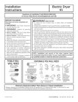
Installation
Instructions
Gas Dryer
01
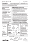
DES I GN
CE
R TI FI E D
4XHVWLRQV"&DOO*(&$5(6RUYLVLWRXU:HEVLWHDW*($SSOLDQFHVFRP
,Q&DQDGDFDOORUYLVLWZZZ*($SSOLDQFHVFD
BEFORE YOU BEGIN
Read these instructions completely and
FDUHIXOO\
• ,03257$17 Save these instructions
for local inspector’s use.
• ,03257$17 Observe all
•
•
•
•
•
•
•
•
governing
codes and ordinances.
1RWHWR,QVWDOOHU Be sure to leave these
instructions with the customer.
1RWH WR &XVWRPHU Keep these
instructions with your Owner’s Manual for
future reference.
Before the old dryer is removed from
service or discarded, remove the dryer
door.
Inspect the dryer exhaust outlet and
straighten the outlet walls if they are bent.
Service information and the wiring
diagram are located in the control console.
Do not allow children on or in the appliance.
Close supervision of children is necessary
when the appliance is used near children.
Install the dryer where the temperature is
above 50°F for satisfactory operation of
the dryer control system.
Product failure due to improper installation
is not covered under the Warranty.
TOOLS YOU WILL
NEED
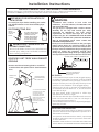
WARNING RISK OF FIRE
•To reduce the risk of severe injury or death, follow all installation instructions.
&ORWKHVGU\HULQVWDOODWLRQPXVWEHSHUIRUPHGE\DTXDOL¿HGLQVWDOOHU
•Install the clothes dryer according to these instructions and in accordance with local
codes. In the absence of local codes, installation must comply with National Fuel Gas
Code, ANSIZ223.1/NFPA 54 or the Canadian Natural Gas and Propane Installation
Code, CSA B149.1.
•California Safe Drinking Water and Toxic Enforcement Act.
This act requires the governor of California to publish a list of substances known to
the state to cause cancer, birth defects or other reproductive harm and requires
businesses to warn customers of potential exposure to such substances. Gas
appliances can cause minor exposure to four of these substances, namely benzene,
carbon monoxide, formaldehyde and soot, caused primarily by the incomplete
combustion of natural gas or LP fuels. Properly adjusted dryers will minimize
incomplete combustion. Exposure to these substances can be minimized further by
properly venting the dryer to the outdoors.
•This dryer must be exhausted to the outdoors.
•Use only 4” rigid metal ducting for exhausting the clothes dryer to the outdoors.
•DO NOTLQVWDOODFORWKHVGU\HUZLWKÀH[LEOHSODVWLFGXFWLQJPDWHULDOV,IÀH[LEOHPHWDO
(semi-rigid or foil-type) duct is installed, it must be UL listed and installed in accordance
with the instructions found in “Connecting The Dryer To House Vent” on page 6 of this
manual. Flexible venting materials are known to collapse, be easily crushed, and trap
OLQW7KHVHFRQGLWLRQVZLOOREVWUXFWGU\HUDLUÀRZDQGLQFUHDVHWKHULVNRI¿UH
•Do not install or store this appliance in any location where it could be exposed to
water and or weather.
•Save these instructions. (Installers: Be sure to leave these instructions with the
customer).
In the state of Massachusetts:
• ,QVWDOODWLRQ PXVW EH SHUIRUPHG E\ D TXDOL¿HG RU OLFHQVHG FRQWUDFWRU
SOXPEHURUJDV¿WWHUTXDOL¿HGRUOLFHQVHGE\WKHVWDWH
• :KHQXVLQJEDOOW\SHJDVVKXWRȹYDOYHVWKH\VKDOOEH7KDQGOHW\SH
• $ÀH[LEOHJDVFRQQHFWRUZKHQXVHGPXVWQRWH[FHHGIHHW
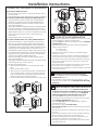
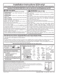
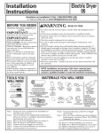
M ATERIALS YOU WILL NEED
4" DIA. METAL DUCT
(RECOMMENDED)
4" DIAM METAL ELBOW
(x2)
4" DIA. FLEXIBLE METAL (SEMI-RIGID)
UL LISTED TRANSITION DUCT
(IF NEEDED)
KIT WX08X10077 (INCLUDES 2 ELBOWS)
10" ADJUSTABLE WRENCHES
8" PIPE WRENCH
SLIP JOINT PLIERS
LEVEL
FLAT BLADE SCREWDRIVER
4" DIA. FLEXIBLE METAL (FOIL TYPE)
UL LISTED TRANSITION DUCT
(IF NEEDED.)
EXHAUST HOOD
PIPE
COMPOUND
SOAP SOLUTION
FOR LEAK DETECTION
(x2)
4" DUCT CLAMPS
OR
4" SPRING CLAMPS
DUCT TAPE
SAFETY GLASSES
(x2)
FLEXIBLE GAS LINE CONNECTOR
234D2217P001
GLOVES
31-16735 10-13 GE
Installation Instructions
0LQLPXP&OHDUDQFH2WKHU7KDQ$OFRYHRU&ORVHW,QVWDOODWLRQ
Minimum clearance to combustible surfaces and for air opening are: 0 in. clearance both sides and 1 in. rear.
Consideration must be given to provide adequate clearance for installation and service.
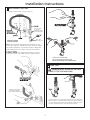
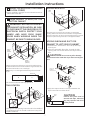
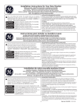
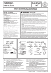
GAS REQUIREMENTS
1 PREPARING FOR INSTALLATION OF
WARNING
NEW DRYER
7,3,QVWDOO\RXUGU\HUEHIRUHLQVWDOOLQJ\RXUZDVKHU
7KLVZLOODOORZEHWWHUDFFHVVZKHQLQVWDOOLQJGU\HU
H[KDXVW
• Installation must conform to local codes and
RUGLQDQFHVRULQWKHLUDEVHQFHWKH1$7,21$/)8(/
*$6&2'($16,=
7KLV JDV GU\HU LV HTXLSSHG ZLWK D 9DOYH %XUQHU
$VVHPEO\ IRU XVH RQO\ ZLWK QDWXUDO JDV 8VLQJ
FRQYHUVLRQ NLW :(; \RXU ORFDO VHUYLFH
RUJDQL]DWLRQ FDQ FRQYHUW WKLV GU\HU IRU XVH ZLWK
SURSDQH/3JDV$//&219(56,2160867%(0$'(
BY PROPERLY TRAINED AND QUALIFIED PERSONNEL
AND IN ACCORDANCE WITH LOCAL CODES AND
25',1$1&(5(48,5(0(176
7KHGU\HUPXVWEHGLVFRQQHFWHGIURPWKHJDVVXSSO\
SLSLQJ V\VWHP GXULQJ DQ\ SUHVVXUH WHVWLQJ RI WKDW
V\VWHPDWDWHVWSUHVVXUHLQH[FHVVRI36,.3D
7KHGU\HUPXVWEHLVRODWHGIURPWKHJDVVXSSO\SLSLQJ
V\VWHP E\ FORVLQJ WKH HTXLSPHQW VKXWRȹ YDOYH
GXULQJDQ\SUHVVXUHWHVWLQJRIWKHJDVVXSSO\SLSLQJ
RIWHVWSUHVVXUHHTXDOWRRUOHVVWKDQ36,.3D
DRYER GAS SUPPLY CONNECTION
DISCONNECTING GAS
TURN GAS
SHUT-OFF VALVE
TO THE OFF
POSITION.
DISCONNECT AND DISCARD OLD
FLEXIBLE GAS CONNECTOR AND
OLD TRANSITION DUCTING
MATERIAL. REPLACE WITH NEW
CSA(AGA) APPROVED FLEXIBLE
GAS LINE CONNECTOR AND UL
APPROVED TRANSITION DUCT.
:$51,1*1(9(55(86(2/'
)/(;,%/(&211(&7256
7KHXVHRIROGÀH[LEOHFRQQHFWRUVFDQFDXVHOHDNVDQG
SHUVRQDO LQMXU\ $OZD\V XVH QHZ ÀH[LEOH FRQQHFWRUV
when installing gas appliances.
5(029,1*/,17)520:$//(;+$867
OPENING
2"
• 5HPRYHDQGGLVFDUGH[LVWLQJSODVWLFRUPHWDOIRLO
WUDQVLWLRQGXFWDQGUHSODFHZLWK8/OLVWHGWUDQVLWLRQ
GXFW
2-5/8"
WALL
INTERNAL DUCT
OPENING
GAS SUPPLY
CHECK THAT EXHAUST
HOOD DAMPER OPENS
AND CLOSES FREELY.
3/8" NPT MALE THREAD GAS SUPPLY
NOTE: Add to vertical dimension
the distance between cabinet
bottom to floor.
• A 1/8-in.National Pipe Taper thread plugged tapping,
accessible for test gauge connection, must be installed
immediately upstream of the gas supply connection to
the dryer. Contact your local gas utility should you have
questions on the installation of the plugged tapping.
• Supply line is to be 1/2-in. rigid pipe and equipped with
DQ DFFHVVLEOH VKXWRȺ ZLWKLQ IW RI DQG LQ WKH VDPH
room with the dryer.
8VH SLSH WKUHDG VHDOHU FRPSRXQG RU 7HÀRQ WDSH
appropriate for natural or LP gas.
<RXPXVWXVHZLWKWKLVGU\HUDÀH[LEOHPHWDOFRQQHFWRU
listed connector ANSI Z21.24 / CSA 6.10. The length of
the connect shall not exceed 3 ft.
&RQQHFWÀH[LEOHPHWDOFRQQHFWRUWRGU\HUDQGJDVVXSSO\
2SHQVKXWRȺYDOYH
TILT THE DRYER SIDEWAYS
AND REMOVE THE FOAM
SHIPPING PADS BY
PULLING AT THE SIDES
AND BREAKING THEM
AWAY FROM THE DRYER
LEGS. BE SURE TO
REMOVE ALL OF THE
FOAM PIECES AROUND
THE LEGS.
$'-867,1*)25(/(9$7,21
• Gas clothes dryers input ratings are based on sea level
operation and need not be adjusted for operation at or
below 2000 ft. elevation.
For operation at elevations above 2000 ft., input ratings
should be reduced at a rate of 4 percent for each 1000
ft. above sea level.
• Installation must conform to local codes and ordinances or,
in their absence, the NATIONAL FUEL GAS CODE, ANSI Z223.
2
Installation Instructions
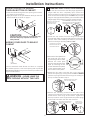
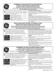
RECONNECTING GAS
Listed connector ANSI Z21.24 / CSA 6.10
FLARE
NPT
1/8" NPT PIPE
PLUG FOR
CHECKING GAS
INLET PRESSURE
3/8" NPT
PIPE SIZE
AT LEAST 1/2"
Note:7KHFRQQHFWRUDQG¿WWLQJVDUHGHVLJQHGIRUXVH
only on the original installation and are not to be reused
IRUDQRWKHUDSSOLDQFHRUDWDQRWKHUORFDWLRQ.HHSÀDUH
end of adaptor free of grease, oil and thread sealant.
CAUTION: Use adapters as shown. Connector
nuts must not be connected directly to pipe threads.
TIGHTEN ALL CONNECTIONS
USING TWO ADJUSTABLE WRENCHES.
DO NOT OVERTORQUE GAS CONNECTIONS!
LEAK TEST
WARNING: 1(9(586($123(1
)/$0(727(67)25*$6/($.6
TIGHTEN THE FLEXIBLE
GAS LINE USING TWO
ADJUSTABLE WRENCHES.
eck all connections for leaks with soapy solution or equivalent.
ply soap solution. Leak test solution must not contain ammonia
ch could cause damage to the brass fittings. If leaks are found,
se valve, retighten the joint, and repeat the soap test.
3
Installation Instructions
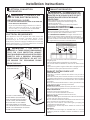
ELECTRICAL CONNECTION
(;+$867,1)250$7,21
INFORMATION
:$51,1* IN CANADA AND IN THE
81,7('67$7(67+(5(48,5('(;+$867'8&7
',$0(7(5,6,1PP'212786('8&7
/21*(57+$163(&,),(',17+((;+$867
/(1*7+7$%/(
:$51,1*TO REDUCE THE
5,6.2)),5((/(&75,&$/6+2&.
AND PERSONAL INJURY:
8VLQJH[KDXVWORQJHUWKDQVSHFL¿HGOHQJWKZLOO
• Increase the drying times and the energy cost.
• Reduce the dryer life.
$FFXPXODWHOLQWFUHDWLQJDSRWHQWLDO¿UHKD]DUG
7KHFRUUHFWH[KDXVWLQVWDOODWLRQLVYOUR
RESPONSIBILITY3UREOHPVGXHWRLQFRUUHFWLQVWDOODWLRQ
DUHQRWFRYHUHGE\WKHZDUUDQW\
Remove and discard existing plastic or metal foil transition
duct and replace with UL listed transition duct.
The 0$;,080$//2:$%/( duct length and number of
bends of the exhaust system depends upon the type of
duct, number of turns, the type of exhaust hood (wall cap),
and all conditions noted below. The maximum duct length
for rigid metal duct is shown in the table below.
• '212786($1(;7(16,21&25'25$1$'$37(5
3/8*:,7+7+,6$33/,$1&(
Dryer must be electrically grounded in accordance
with local codes and ordinances, or in the absence
of local codes, in accordance with the NATIONAL
ELECTRICAL CODE, ANSI/NFPA NO. 70.
ELECTRICAL REQUIREMENTS
This appliance must be supplied with 120V, 60Hz, and
connected to a properly grounded branch circuit,
protected by a 15- or 20- amp circuit breaker or timedelay fuse. If electrical supply provided does not meet the
DERYH VSHFL¿FDWLRQV LW LV UHFRPPHQGHG WKDW D OLFHQVHG
electrician install an approved outlet.
EXHAUST LENGTH
RECOMMENDED MAXIMUM LENGTH
Exhaust Hood Types
Use only for short
run installations
Recommended
:$51,1* 4" DIA.
THIS DRYER IS
(48,33(' $ 7+5((3521* *5281',1*
PLUG FOR YOUR PROTECTION AGAINST
6+2&.+$=$5'$1'6+28/'%(3/8**('
DIRECTLY INTO A PROPERLY GROUNDED
7+5((3521* 5(&(37$&/( '2 127 &87
25 5(029( 7+( *5281',1* 3521*
)5207+,63/8*
4" DIA.
4" DIA.
4"
No. of 90º
Elbows
0
1
2
3
2-1/2"
Rigid
Metal
90
60
45
35
Feet
Feet
Feet
Feet
Rigid
Metal
60
45
35
25
Feet
Feet
Feet
Feet
• For every extra 90° elbow, reduce the allowable vent system
length by 10 ft.
• Two 45° elbows will be treated like one 90° elbow.
• For the side exhaust installations, add one 90° elbow to the
chart.
• The total vent system length includes all the straight portions
and elbows of the system (transition duct included).
ENSURE PROPER GROUND
EXISTS BEFORE USE.
(;+$8676<67(0&+(&./,67
HOOD OR WALL CAP
•Terminate in a manner to prevent back drafts or entry of birds or
other wildlife.
•Termination should present minimal resistance to the exhaust air
ÀRZDQGVKRXOGUHTXLUHOLWWOHRUQRPDLQWHQDQFHWRSUHYHQWFORJJLQJ
•1HYHU install a screen in or over the exhaust duct. This could cause
lint build up.
•Wall caps must be installed at least 12 in. above ground level or any
other obstruction with the opening pointed down.
SEPARATION OF TURNS
For best performance, separate all turns by at least 4 ft. of straight
duct, including distance between last turn and exhaust hood.
TURNS OTHER THAN 90º
• One turn of 45º or less may be ignored.
• Two 45º turns should be treated as one 90º turn.
• Each turn over 45º should be treated as one 90º turn.
SEALING OF JOINTS
•All joints should be tight to avoid leaks. The male end of each section
of duct must point away from the dryer.
•Do not assemble the ductwork with fasteners that extend into the
duct. They will serve as a collection point for lint.
•Duct joints can be made air and moisture-tight by wrapping the
overlapped joints with duct tape.
•Horizontal runs should slope down toward the outdoors 1/4
inch per foot.
INSULATION
Duct work that runs through an unheated area or is near air
conditioning should be insulated to reduce condensation and lint
build-up.
IF LOCAL CODES PERMIT,
AN EXTERNAL GROUND WIRE
(NOT PROVIDED), WHICH MEETS
LOCAL CODES, MAY BE ADDED
BY ATTACHING TO THE GREEN
GROUND SCREW ON THE REAR
OF THE DRYER, AND TO A GROUNDED
METAL COLD WATER PIPE OR OTHER
ESTABLISHED GROUND.
4
Installation Instructions
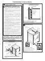
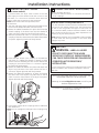
STANDARD REAR EXHAUST
(Vented above floor level)
(;+$867&211(&7,21
:$51,1*TO REDUCE THE
ELBOW HIGHLY
RECOMMENDED
RISK OF FIRE OR PERSONAL INJURY:
• This clothes dryer must be exhausted to the
outdoors.
• We recommend that you install your dryer before
installing your washer. This will permit direct access
for easier exhaust connection.
• Use only 4” rigid metal ducting for the home exhaust
duct.
8VH RQO\ µ ULJLG PHWDO RU 8/OLVWHG ÀH[LEOH PHWDO
(semi-rigid or foil-type) duct to connect the dryer
to the home exhaust duct. It must be installed
in accordance with the instructions found in
“Connecting The Dryer To House Vent” on page 6 of
this manual.
• Do not terminate exhaust in a chimney, a wall,
a ceiling, gas vent, crawl space, attic, under an
HQFORVHG ÀRRU RU LQ DQ\ RWKHU FRQFHDOHG VSDFH
of a building. The accumulated lint could create a
potential ¿UHKD]DUG
• Never terminate the exhaust into a common duct
with a kitchen exhaust system. A combination of
JUHDVHDQGOLQWFUHDWHVDSRWHQWLDO¿UHKD]DUG
'RQRWXVHGXFWORQJHUWKDQVSHFL¿HGLQWKHH[KDXVW
length table. Longer ducts can accumulate lint,
FUHDWLQJDSRWHQWLDO¿UHKD]DUG
• Never install a screen in or over the exhaust duct.
This will cause lint to accumulate, creating a
SRWHQWLDO¿UHKD]DUG
• Do not assemble ductwork with any fasteners
that extend into the duct. These fasteners can
DFFXPXODWHOLQWFUHDWLQJDSRWHQWLDO¿UHKD]DUG
• Do not obstruct incoming or exhausted air.
• Provide an access for inspection and cleaning of
the exhaust system, especially at turns and joints.
Exhaust system shall be inspected and cleaned at
least once year.
RECOMMENDED
CONFIGURATION
TO MINIMIZE
EXHAUST
BLOCKAGE.
ELBOW HIGHLY
RECOMMENDED
NOTE: ELBOWS WILL PREVENT DUCT
KINKING AND COLLAPSING.
8 /(9(/,1*'5<(5
LEVEL
FRONT-TO-BACK.
LEVEL
SIDE-TO-SIDE.
THIS DRYER COMES READY FOR REAR
(;+$867,1* ,) 63$&( ,6 /,0,7(' 86(
THE INSTRUCTIONS IN SECTION 9 TO
(;+$867',5(&7/<)5207+(6,'(625
%277202)7+(&$%,1(7
STANDARD REAR EXHAUST
(Vented at floor level)
FOR STRAIGHT LINE INSTALLATION, CONNECT THE DRYER EXHAUST TO
THE EXTERNAL EXHAUST HOOD USING DUCT TAPE OR CLAMP.
CSA (AGA) APPROVED
NEW FLEXIBLE GAS
LINE CONNECTOR
EXTERNAL
DUCT
OPENING
GAS
INLET
PIPE
4 LEVELING LEGS
STAND THE DRYER UPRIGHT NEAR THE
FINAL LOCATION AND ADJUST THE 4 LEVELING
LEGS TO MATCH THE HEIGHT OF YOUR WASHER.
ADJUST THE 2 ANTI-TIP LEGS TO CONTACT
THE FLOOR.
DUCT TAPE OR
DUCT CLAMP
4" METAL DUCT
(CUT TO PROPER
LENGTH)
DUCT TAPE OR
DUCT CLAMP
NOTE: WE STRONGLY RECOMMEND SOLID METAL EXHAUST DUCTING.
HOWEVER, IF FLEXIBLE DUCTING IS USED IT MUST BE UL-LISTED METAL
NOT PLASTIC.
5
2 ANTI-TIP LEGS
Installation Instructions
&211(&7,1*7+('5<(572+286(9(17
DON’T
RIGID METAL TRANSITION DUCT
DO NOT
SIT DRYER
ON FLEXIBLE
EXHAUST
• For best drying performance, a rigid metal transition duct is
recommended.
• Rigid metal transitions ducts reduce the risk of crushing and kinking.
8//,67(')/(;,%/(0(7$/6(0,5,*,'75$16,7,21'8&7
,IULJLGPHWDOGXFWFDQQRWEHXVHGWKHQ8/OLVWHGÀH[LEOH
metal (semi-rigid) ducting can be used (Kit WX08X10077).
1HYHULQVWDOOÀH[LEOHPHWDOGXFWLQZDOOVFHLOLQJVÀRRUVRU
other enclosed spaces.
7RWDOOHQJWKRIÀH[LEOHPHWDOGXFWVKRXOGQRWH[FHHGIHHWP
• For many applications, installing elbows at both the dryer
and the wall is highly recommended (see illustrations below).
Elbows allow the dryer to sit close to the wall without kinking
and or crushing the transition duct, maximizing drying
performance.
• Avoid resting the duct on sharp objects.
DO NOT USE
EXCESSIVE
EXHAUST
LENGTH
DO NOT
CRUSH
FLEXIBLE
EXHAUST
AGAINST
WALL.
9 $/&29(25&/26(7,167$//$7,21
• If your dryer is approved for installation in an alcove or closet,
it will be stated on a label on the dryer back.
• The dryer MUST be vented to the outdoors. See the (;+$867
INFORMATION section.
• Minimum clearance between dryer cabinet and adjacent
walls or other surfaces is:
0 in. either side
3 in. front and rear
0LQLPXPYHUWLFDOVSDFHIURPÀRRUWRRYHUKHDGFDELQHWV
ceiling, etc. is 52 in.
• Closet doors must be louvered or otherwise ventilated and
must contain a minimum of 60 sq. in. of open area equally
distributed. If the closet contains both a washer and a dryer,
doors must contain a minimum of 120 sq.in. of open area
equally distributed.
• The closet should be vented to the outdoors to prevent gas
pocketing in case of a gas leak in the supply line.
• No other fuel-burning appliance shall be installed in the same
closet with the dryer.
8//,67(')/(;,%/(0(7$/)2,/7<3(75$16,7,21'8&7
• In special installations, it may be necessary to connect the
GU\HUWRWKHKRXVHYHQWXVLQJDÀH[LEOHPHWDOIRLOW\SHGXFW
$8/OLVWHGÀH[LEOHPHWDOIRLOW\SHGXFWPD\EHXVHG21/<
LQLQVWDOODWLRQVZKHUHULJLGPHWDORUÀH[LEOHPHWDOVHPLULJLG
ducting cannot be used AND where a 4” diameter can be
maintained throughout the entire length of the transition duct.
,Q&DQDGDDQGWKH8QLWHG6WDWHVRQO\WKHÀH[LEOHPHWDOIRLO
type) ducts that comply with the “Outline for Clothes Dryer
Transition Duct Subject 2158A” shall be used.
1HYHULQVWDOOÀH[LEOHPHWDOGXFWLQZDOOVFHLOLQJVÀRRUVRU
other enclosed spaces.
7RWDOOHQJWKRIÀH[LEOHPHWDOGXFWVKRXOGQRWH[FHHGIHHWP
• Avoid resting the duct on sharp objects.
• For best drying performance:
1. Slide one end of the duct over the clothes dryer outlet
pipe.
2. Secure the duct with a clamp.
3. With the dryer in its permanent position, extend the duct
to its full length. Allow 2” of duct to overlap the exhaust
SLSH&XWRȺDQGUHPRYHH[FHVVGXFW.HHSWKHGXFWDV
VWUDLJKWDVSRVVLEOHIRUPD[LPXPDLUÀRZ
4. Secure the duct to the exhaust pipe with the other clamp.
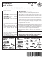
10 BATHROOM OR BEDROOM INSTALLATION
• The dryer MUST be vented to the outdoors. See (;+$867
INFORMATION section 6.
• The installation must conform with local codes or, in the
absence of local codes, with the 1$7,21$/)8(/*$6&2'(
$16,=
DO
11 MOBILE OR MANUFACTURED HOME INSTALLATION
• Installation must conform to the MANUFACTURED HOME
&216758&7,216$)(7<67$1'$5'7,7/(3$57
or, when such standard is not applicable, with AMERICAN
1$7,21$/67$1'$5')2502%,/(+20(12%.
• The dryer MUST be vented to the outdoors with the
termination securely fastened to the mobile home structure.
(See (;+$867,1)250$7,21 section 6.)
• The vent MUST NOT be terminated beneath a mobile or
manufactured home.
• The vent duct material MUST BE METAL.
• .,7'0867 be used to attach the dryer securely to
the structure.
• The vent MUST NOT be connected to any other duct, vent, or
chimney.
• Do not use sheet metal screws or other refastening devices
which extend into the interior of the exhaust vent.
• Provide an opening with a free area of at least 25 sq. in.or
introduction of outside air into the dryer room.
• Stacking of a gas dryer is not permitted in a mobile home or
manufactured home.
ELBOW HIGHLY
RECOMMENDED
ELBOWS HIGHLY
RECOMMENDED
6
Installation Instructions
ADDING NEW DUCT
GARAGE INSTALLATION (IF ALLOWED
%</2&$/&2'(6
FIXING
HOLE
• Dryers installed in garages must be elevated 18 inches
FPDERYHWKHÀRRU
PORTION "A"
'5<(5(;+$867725,*+7/()725
BOTTOM CABINET
:$51,1* BEFORE PERFORMING
7+,6(;+$867,167$//$7,21%(685(
TO DISCONNECT THE DRYER FROM ITS
(/(&75,&$/ 6833/< 3527(&7 <285
HANDS AND ARMS FROM SHARP
EDGES WHEN WORKING INSIDE THE
&$%,1(7%(685(72:($5*/29(6
LEFT SIDE
EXHAUST
Reconnect the cut portion (A) of the duct to the blower
housing. Make sure that the shortened duct is aligned with
the tab in the base. Use the screw saved previously to secure
the duct in place through the tab on the appliance base.
ADDING ELBOW AND DUCT FOR
(;+$86772/()76,'(2)&$%,1(7
• Preassemble 4” elbow with 4” duct. Wrap duct tape
around joint.
,QVHUWGXFWDVVHPEO\HOERZ¿UVWWKURXJKWKHVLGH
opening and connect the elbow to the dryer internal
duct.
REMOVE
SCREW
AND SAVE.
CAUTION:
%HVXUHQRWWRSXOORUGDPDJH
WKHHOHFWULFDOZLUHVLQVLGHWKHGU\HUZKHQLQVHUWLQJWKH
GXFW
REMOVE
DESIRED
KNOCKOUT
(ONE ONLY).
Detach and remove the bottom, right or left side knockout
as desired. Remove the screw inside the dryer exhaust duct
and save. Pull the duct out of the dryer.
EXHAUST CAN
BE ADDED TO
LEFT OR RIGHT SIDE
Note: Only 4” round rigid metal ducting allowed inside
dryer.
FIXING HOLE
B
DUCT
TAPE
A
9"
Cut the duct as shown and keep portion A.
TAB LOCATION
• Apply duct tape as shown on the joint between the
dryer internal duct and the elbow.
BEND TAB
UP 45 o
DUCT
TAPE
Through the rear opening, locate the tab in the middle of
the appliance base. Lift the tab to about 45º using a flat
blade screwdriver.
7
CAUTION:
Internal duct joints must be
VHFXUHG ZLWK WDSH RWKHUZLVH
they may separate and cause
DVDIHW\KD]DUG
Installation Instructions
14 CHANGING DIRECTION OF DOOR OPENING
$'',1*(/%2:)25(;+$867
THROUGH BOTTOM OF CABINET
1. 2SHQWKHGRRUDQGUHPRYHWKH¿OOHUSOXJVRSSRVLWHWKH
hinges. With the door completely open, remove the
bottom screws from each hinge on the dryer face. Insert
these screws about half way into the TOP holes, for each
KLQJHRQWKHRSSRVLWHVLGHZKHUH\RXUHPRYHGWKH¿OOHU
SOXJV$SSO\¿UPSUHVVXUHWRJHWWKHVFUHZVVWDUWHG
• Insert the elbow through the rear opening and connect
it to the dryer internal duct.
• Apply duct tape on the joint between the dryer internal
duct and elbow, as shown on page 7.
REMOVE 4 PLUGS AND KEEP
FOR INSERTION INTO
THE OPPOSITE SIDE
CAUTION:
REMOVE BOTTOM SCREW FROM EACH HINGE
AND INSTALL HALF WAY INTO EACH TOP OF
OPPOSITE HINGE HOLES
2. Loosen the top screws from each hinge on the dryer
face half way. With one hand holding the top of the door
and the other hand holding the bottom, remove the
door from the dryer by lifting it UP and OFF.
Internal duct joints must be secured with tape,
otherwise they may separate and cause a
safety hazard.
$'',1*&29(53/$7(725($52)
CABINET
LOOSEN EACH TOP HINGE
SCREW HALF WAY AND LIFT
THE DOOR UP AND OFF
3. Remove the blind plate from
the hinge side of the dryer
by removing its two screws.
Remove the strike plate
from the opposite side of the
dryer by removing its two
screws. Reinstall the plates,
on the opposite sides, using
two screws in each plate.
PL ATE
(KIT WE1M454)
Connect standard metal elbows and ducts to complete
the exhaust system. Cover back opening with a plate (Kit
WE1M454) available from your local service provider. Place
GU\HULQ¿QDOORFDWLRQ
SWITCH
BLIND
PLATE
STRIKE
PLATE
FRONT PANEL
4. Rotate the door 180º. Insert the door on the opposite
side of the opening by moving the door ON and DOWN
until the top hinge and the bottom hinge are resting on
the top screws inserted in step 1.
:$51,1*1(9(5/($9(7+(
%$&.23(1,1*:,7+2877+(3/$7(
ROTATE DOOR 180º AND HANG
IT ON TOP HINGE SCREWS
5. Remove the remaining screws from the side of the
opening from which the door was removed. With these
screws secure each hinge at the bottom. Tighten the
two top screws on each hinge. Reinsert the plastic plugs
on the side from which the door was removed.
INSTALL AND TIGHTEN BOTTOM
SCREWS AND TIGHTEN TOP
SCREWS
8
INSERT PLUGS
INTO HOLES ON
OPPOSITE SIDE
Installation Instructions
15 CONNECTING INLET HOSES
(on some models)
15 &211(&7,1*,1/(7+26(6FRQW
Turn the water faucet on.
Check for leaks around the ‘’Y’’ connector, faucet and
hose couplings.
To produce steam, the dryer must connect to the cold
water supply. Since the washer must also connect to the
cold water, a “Y” connector is inserted to allow both inlet
hoses to make that connection at the same time.
NOTE: Use the new inlet hoses provided; never
use old hoses.
7XUQWKHFROGZDWHUIDXFHWRȺ5HPRYHWKHZDVKHULQOHW
KRVHIURPWKHZDVKHU¿OOYDOYHFRQQHFWRUFROG
(QVXUHWKHUXEEHUÀDWZDVKHULVLQSODFHDQGVFUHZWKH
IHPDOH FRXSOLQJ RI WKH VKRUW KRVH RQWR WKH ZDVKHU ¿OO
YDOYHFRQQHFWRU7LJKWHQE\KDQGXQWLO¿UPO\VHDWHG
Attach the female end of the ‘’Y’’ connector to the male
FRXSOLQJRIWKHVKRUWKRVH(QVXUHWKHUXEEHUÀDWZDVKHU
LVLQSODFH7LJKWHQE\KDQGXQWLO¿UPO\VHDWHG
WATER SUPPLY REQUIREMENTS
Hot and cold water faucets MUST be installed within 42 in.
(107 cm) of your washer’s water inlet. The faucets MUST
be 3/4 in. (1.9 cm) garden hose-type so inlet hoses can
be connected. Water pressure MUST be between 10 and
120 pounds per square inch. Your water department can
advise you of your water pressure.
NOTE: A water softener is recommended to reduce buildup
of scale inside the steam generator if the home water
supply is very hard.
6(59,&,1*
:$51,1* LABEL ALL WIRES
PRIOR TO DISCONNECTION WHEN
6(59,&,1*&21752/6:,5,1*(55256
CAN CAUSE IMPROPER AND DANGEROUS
23(5$7,21$)7(56(59,&,1*
,167$//$7,21
,QVHUW WKH ¿OWHU VFUHHQ LQ WKH FRXSOLQJ RI WKH ZDVKHU·V
LQOHW KRVH ,I D UXEEHU ÀDW ZDVKHU LV DOUHDG\ LQ SODFH
UHPRYHLWEHIRUHLQVWDOOLQJWKH¿OWHUVFUHHQ$WWDFKWKLV
coupling to one male end of the ‘’Y’’ connector. Tighten
E\KDQGXQWLO¿UPO\VHDWHG
(QVXUHWKHUXEEHUÀDWZDVKHULVLQSODFHDQGDWWDFKWKH
dryer’s long inlet hose to the other male end of the ‘’Y’’
FRQQHFWRU7LJKWHQE\KDQGXQWLO¿UPO\VHDWHG
(QVXUH WKH UXEEHU ÀDW ZDVKHU LV LQ SODFH DQG DWWDFK
WKH RWKHU HQG RI WKH GU\HU·V ORQJ LQOHW KRVH WR WKH ¿OO
valve connector at the bottom of the dryer back panel.
7LJKWHQE\KDQGXQWLO¿UPO\VHDWHG
For servicing phone numbers for replacement parts, and
other information, refer to Owner’s Manual or visit our
Web site.
REGISTER YOUR NEW APPLIANCE TO RECEIVE ANY
IMPORTANT PRODUCT NOTIFICATIONS.
Please go to www.GEAppliances.com or mail in your
Product Registration Card.
For questions on installation, call: 800.626.2000 (US) or
800-561-3344 (Canada).
Using pliers, tighten all the couplings with an additional
two–thirds turn.
NOTE: Do not overtighten. Damage to the couplings may
result.
9
Notes
10
Notes
11
Notes
12