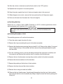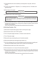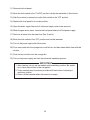
1
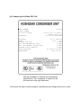
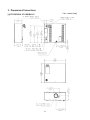
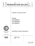
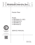
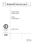
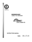
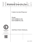
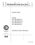
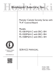
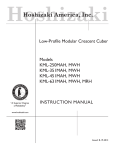
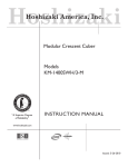
Hoshizaki
Hoshizaki America, Inc.
Modular Flaker
Serenity Series
Model
FS-1001MLH/-C
Including
Condensing Unit Model SRC-10H
“A Superior Degree
of Reliability”
INSTRUCTION MANUAL
www.hoshizaki.com
Issued: 7-29-2005
Revised: 12-27-2005
FOREWORD
IMPORTANT
Only qualified service technicians should attempt to install, service or maintain
this icemaker. No such installation, service or maintenance should be undertaken
until the technician has thoroughly read this Instruction Manual. Likewise, the
owner/manager should not proceed to operate the icemaker until the installer has
instructed them on its proper operation.
HOSHIZAKI provides this manual primarily to assist qualified service technicians in the
installation, maintenance and service of the icemaker.
Should the reader have any questions or concerns which have not been satisfactorily
addressed, please call or write to the HOSHIZAKI Technical Support Department for
assistance.
HOSHIZAKI AMERICA, INC.
618 Highway 74 South
Peachtree City, GA 30269
Attn: HOSHIZAKI Technical Support Department
Phone: 1-800-233-1940 Technical Service
(770) 487-2331
Fax:
1-800-843-1056
(770) 487-3360
Web Site: www.hoshizaki.com
NOTE: To expedite assistance, all correspondence/communication MUST include the
following information:
• Model Number
• Serial Number
• Complete and detailed explanation of the problem
2
• Please review this manual. It should be read carefully before the icemaker is installed
and operated. Only qualified service technicians should install, service and maintain the
icemaker. This manual should be made available to the technician prior to installation,
maintenance or service.
• Keep this manual with the icemaker for later reference.
CONTENTS
I. Specifications .................................................................................................................... 4
1. Nameplate Rating ........................................................................................................ 4
[a] FS-1001MLH, FS-1001MLH-C .............................................................................. 4
[b] Condensing Unit Model SRC-10H ........................................................................ 5
2. Dimensions/Connections ............................................................................................. 6
[a] FS-1001MLH, FS-1001MLH-C .............................................................................. 6
[b] With Storage Bin .................................................................................................... 7
[c] Condensing Unit Model SRC-10H ........................................................................ 8
II. Installation and Operating Instructions .............................................................................. 9
1. Checks Before Installation ............................................................................................ 9
2. How to Remove Panels ................................................................................................ 9
3. Location ...................................................................................................................... 10
4. Setup .......................................................................................................................... 10
5. Electrical Connection ................................................................................................. 11
6. Installation of Remote Condensing Unit ..................................................................... 11
[a] Checks Before Installation ................................................................................... 11
[b] Location ............................................................................................................... 11
[c] Setup ................................................................................................................... 12
[d] Electrical Connection .......................................................................................... 13
7. Water Supply and Drain Connections ......................................................................... 14
8. Timer Setting .............................................................................................................. 15
9. Final Checklist ............................................................................................................ 16
10. Startup ...................................................................................................................... 17
11. Preparing the Icemaker for Long Storage ................................................................. 18
III. Cleaning and Maintenance ............................................................................................ 19
1. Cleaning and Sanitizing Instructions .......................................................................... 19
[a] Cleaning Solution ................................................................................................ 19
[b] Cleaning Procedure ............................................................................................ 20
[c] Sanitizing Solution............................................................................................... 21
[d] Sanitizing Procedure - Initial ................................................................................ 21
[e] Sanitizing Procedure - Final ................................................................................ 22
2. Maintenance Instructions ............................................................................................ 24
3
I. Specifications
1. Nameplate Rating
[a] FS-1001MLH, FS-1001MLH-C
HOSHIZAKI ICE MAKER
MODEL NUMBER
SERIAL NUMBER
AC SUPPLY VOLTAGE
COMPRESSOR
GEAR MOTOR
FAN MOTOR
OTHER
MAXIMUM FUSE SIZE
MAX. HACR BREAKER(USA ONLY)
MAX. CIRC BREAKER (CANADA ONLY)
MINIMUM CIRCUIT AMPACITY
DESIGN PRESSURE
REFRIGERANT
FS-1001MLH
115-120/60/1
--- --- --120V 3.0FLA 1/4HP
--- --- --120V
0.53A
15 AMPS
15 AMPS
15 AMPS
15 AMPS
HI-427PSI LO-230PSI
404A
See the nameplate for electrical and refrigeration
specifications. This nameplate is located on the
left-hand side of the rear panel.
IMPORTANT
This icemaker is designed for connection to HOSHIZAKI CONDENSING
UNIT, Model SRC-10H only! CONNECTION TO ANOTHER CONDENSING
UNIT WILL VOID WARRANTY.
We reserve the right to make changes in specifications and design without prior notice.
NOTE: Only the “MODEL NUMBER” is replaced for FS-1001MLH-C.
4
[b] Condensing Unit Model SRC-10H
MODEL NUMBER
SERIAL NUMBER
AC SUPPLY VOLTAGE
SRC-10H
208-230/60/1 (3 WIRE W/
NEUTRAL FOR 115V)
208-230V 6.5RLA 46LRA
COMPRESSOR
FAN MOTOR
OTHER
MAXIMUM FUSE SIZE
MAX. HACR BREAKER(USA ONLY)
MAX. CIRC BREAKER (CANADA ONLY)
MINIMUM CIRCUIT AMPACITY
DESIGN PRESSURE
REFRIGERANT
115V 1.3FLA 65W
120V
0.2A
20 AMPS
20 AMPS
20 AMPS
20 AMPS
HI-427PSI LO-230PSI
404A 8lb 2oz.
See the nameplate for electrical and refrigeration
specifications. This nameplate is located on the
left-hand side of the right-side panel.
We reserve the right to make changes in specifications and design without prior notice.
5
2. Dimensions/Connections
Unit = inches [mm]
[a] FS-1001MLH, FS-1001MLH-C
6
[b] With Storage Bin
Unit = inches [mm.]
7
[c] Condensing Unit Model SRC-10H
8
II. Installation and Operating Instructions
1. Checks Before Installation
WARNING
Remove shipping carton, tape(s) and packing. If packing material is left in
the icemaker, it will not work properly.
IMPORTANT
Ensure all components, fasteners and thumbscrews are securely in place.
1) Remove all panels to prevent damage when installing the icemaker. (See “2. How to
Remove Panels.”)
2) Remove the package containing the accessories from inside the icemaker.
3) Remove the protective plastic film from the panels. If the icemaker has been exposed
to the sun or to heat, remove the film after the icemaker cools.
4) Check that the refrigerant lines do not rub or touch lines or other surfaces.
5) See the nameplate on the rear panel, and check that your supplied voltage
corresponds with the voltage specified on the nameplate.
6) This icemaker requires a storage bin. The recommended storage bin is HOSHIZAKI
ICE STORAGE BIN, Model B-500 series.
7) This icemaker is designed for connection to HOSHIZAKI CONDENSING UNIT,
Model SRC-10H only!
NOTE: CONNECTION TO ANOTHER CONDENSING UNIT WILL VOID
WARRANTY.
2. How to Remove Panels
See Fig. 1
a) Front/Rear Panel ..... Remove the screw(s).
Lift up and pull towards you.
b) Top Panel ................ Lift up.
c) Side Panel ............... Remove the thumbscrew.
Pull up and lift off.
9
Fig. 1
3. Location
WARNING
This icemaker is not intended for outdoor use. Normal operating ambient
temperature should be within +45°F to +100°F; Normal operating water
temperature should be within +45°F to +90°F. Operation of the icemaker for
extended periods outside of these normal temperature ranges may affect
production capacity.
For best operating results:
• Icemaker should not be located next to ovens, grills or other high heat producing
equipment.
• Location should provide a firm and level foundation for the equipment.
• Allow 6" clearance at rear and sides for proper air circulation and ease of maintenance
and /or service should they be required. Allow 24" clearance at top to allow for
removal of the auger.
4. Setup
1) Unpack the storage bin, and attach the four adjustable legs provided (bin accessory)
to the bottom of the storage bin.
2) Position the storage bin in the selected permanent position.
3) Place the icemaker on the top of the storage bin.
4) Secure the icemaker to the storage bin by using
the two braces, four bolts, and four self-tapping screws
provided. The four bolts come attached to the icemaker.
Use the four self-tapping screws to make the appropriate
holes in the storage bin. See Fig. 2.
5) Insure a proper seal between the icemaker and the
storage bin.
6) Level the icemaker/storage bin in both the
left-to-right and front-to-rear directions. Adjust
the storage bin legs to level the icemaker.
Fig. 2
7) Replace the icemaker's panels. Secure the front panel and rear panel
with the proper screw(s) and each side panel with the proper thumbscrew.
10
5. Electrical Connection
This icemaker must have an independent power supply or receptacle of proper capacity.
See the nameplate.
6. Installation of Remote Condensing Unit
[a] Checks Before Installation
1) Unpack and remove shipping carton, tape(s) and packing.
2) Check that the refrigerant lines do not rub or touch lines or other surfaces, and that the fan
blade turns freely.
3) Make sure that the icemaker, line sets and remote condensing unit all use R-404A
refrigerant.
[b] Location
The condensing unit must be positioned in a permanent site under the following
guidelines.
• A firm and flat site.
• A dry and well ventilated area with 24" clearance on both front and rear for ease of
maintenance and service should they be required.
• Normal condenser ambient temperature: -4°F to +122°F. Temperatures not within this
operating range may affect the production capacity of the icemaker.
• The maximum line length is 55 feet. Vertical distance between the condensing unit and
icemaker should not exceed 30 feet above or 10 feet below the icemaker.
Fig. 3
Note: If the recommended installation guidelines are not followed, icemaker
performance may be reduced.
11
[c] Setup
1) Secure the legs to the condensing unit with eight M8 x 16 mm hexagon bolts and M8 nuts
as shown in the illustration. See Fig. 4.
Note: Locate the legs symmetrically.
2) The legs have eight mounting holes. Secure the legs with eight bolts (not included).
3) Install line sets. Precharged tubing kits, available as optional equipment from
HOSHIZAKI AMERICA, are recommended.
To fabricate line sets:
a. Install enough length of two copper tubings between the icemaker and the condensing
unit. See Fig. 5.
• The maximum line length is 55 feet.
• Vertical distance between the condensing unit and icemaker should not exceed 30
feet above or 10 feet below the icemaker.
• If the vertical distance between the condensing unit and icemaker is greater than 18
feet, a p-trap (5/8" OD tubing) must be installed in the suction line. The p-trap must
be within 18 vertical feet of both the condensing unit and the icemaker. This will
ensure sufficient oil return to the compressor.
b. Insulate the two copper tubings separately.
c. Install Parker quick connect couplings on each end.
Fig. 5
Fig. 4
4) Line sets fabricated in the field should be evacuated through the charging ports on the
Parker quick connect couplings and charged with R-404A refrigerant vapor to a pressure
of 15-30 PSIG.
Note: Factory fabricated tubing kits are precharged and do not need to be evacuated.
12
5) Remove the plastic caps protecting the couplings. Apply two drops of POE oil to the male
threads of the couplings. Attach the two refrigerant lines to the male couplings on the
icemaker and the remote condensing unit. The couplings must be tightened 1/4 turn
beyond fully seated. Each refrigerant line must be connected as follows:
Icemaker suction refrigerant line - 5/8" OD tubing
Icemaker liquid refrigerant line - 1/4" OD tubing
Note: Make the connections at the remote condensing unit first and then at the icemaker.
[d] Electrical Connection
WARNING
1. This condensing unit must have a separate power supply. See the
nameplate.
2. This condensing unit requires a ground that meets the national and local
electrical code requirements. To prevent possible electrical shock to
individuals or extensive damage to equipment, install a proper ground wire to
this condensing unit.
• The opening for the power supply connection is 7/8" DIA to fit a 1/2" trade size conduit.
• Usually an electrical permit and services of a licensed electrician are required.
• Installation of an external power disconnect may be required by local code.
1) Remove the louver panel.
2) Remove the control box cover.
3) Connect the three loose leads in the control box to the power supply.
Note: The white lead must be attached to the neutral line.
4) Replace the control box cover and the louver panel in their correct positions.
Note: The icemaker and condensing unit have independent power supply circuits.
Fig. 6
13
7. Water Supply and Drain Connections
See Fig. 7
• External filters or strainers may be required depending on the water quality.
• Water supply inlet is 1/2" female pipe thread (FPT).
• A water supply line shut-off valve and drain valve should be installed. A minimum of 3/8"
OD copper tubing is recommended for the water supply lines.
• Water supply pressure should be a minimum of 10 PSIG and a maximum of 113 PSIG. If
the pressure exceeds 113 PSIG, the use of a pressure reducing valve is required.
• Drain outlet for icemaking is 3/4" FPT. The icemaker drain piping connections must be
made separately from the bin drain piping connections.
• A vented tee connection is required for proper flow.
• The drains must have 1/4" fall per foot on horizontal runs to get a good flow.
• The drains should not be piped directly to the sewer system. An air gap of a minimum of
2 vertical inches should be between the end of the drain pipe from the icemaker or the ice
bin and the floor drain.
• A plumbing permit and services of a licensed plumber may be required in some areas.
Fig. 7
14
8. Timer Setting
See Fig. 8
The ice machine is equipped with an adjustable timer in the control box. It controls the
amount of time the machine waits before shutting down after ice is detected by the bin
control; the timer thereby controls the ice level in the bin or dispenser. The timer is factory
set to the minimum delay of 10 seconds.
Observe the following guidelines when selecting a timer setting.
• When installed on a Hoshizaki bin, any timer setting is acceptable. Increasing the timer
setting will allow a higher level of ice in the bin before the ice machine shuts down.
• When installed on a Lancer dispenser designed for cubelet ice, the timer setting must
remain at 10 seconds.
• For other dispenser applications, the ice level at shutoff may need to be adjusted
depending on the dispenser agitation or dispense method. Observe the ice level in the bin
after the unit cycles off with the 10 second setting and adjust as necessary for the proper
fill level.
10
1000
Timer Setting Control
Fig. 8
15
9. Final Checklist
1) Is the icemaker level?
2) Is the icemaker in a site where the ambient temperature is within +45°F to +100°F and the
water temperature within +45°F to +90°F all year around?
3) Is there at least 6" clearance at rear and sides and 24" at top for maintenance or service?
4) Have all shipping carton, tape(s) and packing been removed from the icemaker?
5) Are all components, fasteners and thumbscrews securely in place?
6) Have all electrical and piping connections been made?
7) Has the power supply voltage been checked or tested against the nameplate rating?
8) Are the water supply line shut-off valve and drain valve installed? Has the water supply
pressure been checked to ensure a minimum of 10 PSIG and a maximum of 113 PSIG?
Note: The icemaker stops running when the water supply is OFF or when the pressure is
below 10 PSIG. When the proper water pressure is restored, the icemaker
automatically starts running again.
9) Have the compressor hold down bolts and the refrigerant lines been checked against
vibration and possible failure?
10) Has the bin control switch been checked for correct operation? To check, use an object
to cover the chute opening on the bottom of the icemaker. The pump down solenoid
should de-energize within 90 seconds.
11) Has the secondary bin control been checked for correct operation? Move the actuator
located in the top of the chute. The gear motor should stop in 6 seconds.
12) Has the end user been given the instruction manual, and instructed on how to operate
the icemaker and the importance of the recommended periodic maintenance?
13) Has the end user been given the name and telephone number of an authorized service
agent?
14) Has the warranty tag been filled out and forwarded to the factory for warranty
registration?
16
10. Startup
IMPORTANT
1. The condensing unit is shipped with the contacts of the secondary low
pressure switch open. Once power is supplied to the condensing unit, wait at
least 4 hours before starting the unit. This will allow the system to settle and
refrigerant to evaporate from oil in the compressor. To start the unit, press the
manual reset button on the secondary low pressure switch. Doing this will
prevent damage to the compressor.
2. If the unit is turned off, wait for at least 3 minutes before restarting the
icemaker to prevent damage to the evaporator.
3. In the event of a power failure that is less than 3 minutes in duration, the gear
motor fuse in the ice machine could blow upon restart. If this occurs, turn off
the machine, replace the fuse and wait at least 3 minutes before restarting.
1) Clean the storage bin. (See “III. 2. Maintenance Instructions.”)
2) Open the water supply line shut-off valve.
3) Move the flush switch on the control box to the “ICE” position.
4) Turn on the power switch on the control box.
5) Replace all exterior panels in their correct positions.
6) Turn on the power supply.
17
11. Preparing the Icemaker for Long Storage
See Fig. 9
WARNING
When shutting off the icemaker for an extended time, drain out all water from the
water line and remove the ice from the storage bin. The storage bin should be
cleaned and dried. Drain the icemaker to prevent damage to the water supply
line at sub-freezing temperatures, using air or carbon dioxide. Shut off the
icemaker until the proper ambient temperature is resumed.
1) Run the icemaker with the water supply line shut-off valve closed.
2) Open the drain valve and blow out the water inlet line by using air pressure.
3) Turn off the power supply.
4) Remove the front panel.
5) Move the flush switch on the control box to the “FLUSH” position.
6) Turn on the power supply, and then drain out all water from the water line.
7) Turn off the power supply.
8) Turn off the power switch on the control box.
9) Replace the front panel in its correct position.
10) Close the drain valve.
11) Remove all ice from the storage bin, and clean the bin.
Fig. 9
18
III. Cleaning and Maintenance
IMPORTANT
Ensure all components, fasteners and thumbscrews are securely in place after
any maintenance or cleaning is done to the equipment.
1. Cleaning and Sanitizing Instructions
WARNING
1. HOSHIZAKI recommends cleaning this unit at least once a year. More
frequent cleaning, however, may be required in some existing water
conditions.
2. To prevent injury to individuals and damage to the icemaker, do not use
ammonia type cleaners.
3. Always wear liquid-proof gloves to prevent the cleaning and sanitizing
solutions from coming into contact with skin.
[a] Cleaning Solution
Dilute 4.8 fl. oz. (142 ml) of recommended cleaner Hoshizaki “Scale Away” or
“LIME-A-WAY” (Economics Laboratory, Inc.) with 0.8 gallons (3 l) of warm water. This is a
minimum amount. Make more solution if necessary.
IMPORTANT
For safety and maximum effectiveness, use the solution immediately after
dilution.
19
[b] Cleaning Procedure
The cleaning process will remove lime deposits from the water system.
1) Remove the front panel and top panel, then turn off the power supply.
2) Close the water supply line shut-off valve.
3) Remove all ice from the storage bin.
4) Move the flush switch to the “FLUSH” position.
5) Turn on the power supply and drain out all water from the water line.
6) Turn off the power supply.
7) Remove the control water valve by removing the fitting nut and two mounting screws. Do
not lose the packing.
8) Check the control water valve screen for debris and clean as necessary.
9) Replace the control water valve in its correct position.
10) Remove the strap connecting the spout to the chute assembly.
11) Remove the thumbscrews securing the spout and lift it off.
12) Pour the cleaning solution over the extruding head until the evaporator assembly and
the reservoir are filled and the solution starts to overflow into the drain pan.
Note: If there is excess scale on the extruding head, fill the evaporator assembly and
reservoir as described above, then use a clamp on the reservoir hose between the
reservoir and evaporator assembly to block flow. Pour additional cleaning fluid
over the extruding head until the evaporator assembly is completely full.
13) Replace the spout and strap in their correct positions.
14) Allow the icemaker to sit for about 10 minutes before operation. If you placed a clamp on
the reservoir hose in step 9, remove it before operation.
15) Move the flush switch to the “ICE” position, then turn on the power supply. Replace the
top panel and front panel in their correct positions. Make ice using the solution until the
icemaker stops making ice.
Note: Always discard the contaminated ice produced during this procedure.
16) Remove the front panel.
17) Move the flush switch to the “FLUSH” position to drain the remainder of the solution.
20
18) After the solution is drained, move the flush switch to the “ICE” position.
19) Replace the front panel in its correct position.
20) Open the water supply line shut-off valve and supply water to the reservoir.
21) When the gear motor starts, remove the front panel and turn off the power supply.
22) Drain out all water from the water line. See 4) through 6).
[c] Sanitizing Solution
Dilute 2.5 fl. oz. (74 ml or 5 tbs) of IMS-II Sanitizer or a 5.25% sodium hypochlorite solution
(chlorine bleach) with 5 gallons (19 l) of warm water.
IMPORTANT
For safety and maximum effectiveness, use the solution immediately after
dilution.
[d] Sanitizing Procedure - Initial
The sanitizing process will sanitize the icemaker.
1) Close the water supply line shut-off valve.
2) Remove the strap connecting the spout to the chute assembly.
3) Remove the thumbscrews securing the spout and lift it off. Remove the rubber O-ring and
nylon O-ring at the top of the cylinder and also remove the packing between the spout
and the chute.
4) Pour the sanitizing solution over the extruding head until the evaporator assembly and
the reservoir are filled and the solution starts to overflow into the drain pan.
5) Remove the two thumbscrews securing the proximity switch to the chute assembly.
6) Remove the chute assembly from the icemaker.
7) Remove the packing at the bottom of the ice chute.
8) Remove the three ties and the chute insulation.
9) Remove the six wing nuts and two baffles.
10) Remove the two thumbscrews, the plate and the packing from the top of the ice chute,
then remove the bin control assembly by sliding it slightly toward the chute opening and
lifting it off.
21
11) Disassemble the bin control assembly by removing the two snap pins, shaft and
actuator.
12) Soak the removed parts in .25 gallons (1 l) of sanitizing solution for 10 minutes then
wipe them down.
13) Rinse the parts thoroughly.
IMPORTANT
If the solution is left on these parts, they will rust.
14) Replace all parts in their correct positions.
IMPORTANT
When installing the baffles, make sure that the bent surface (the one without the
studs) faces the actuator so that the bent surface can guide the ice to the center
of the actuator.
15) Move the flush switch to the “ICE” position, then turn on the power supply. Replace the
top panel and front panel in their correct positions. Make ice using the solution until the
icemaker stops making ice.
Note: Always discard the contaminated ice produced during this procedure.
[e] Sanitizing Procedure - Final
1) Remove the front panel and top panel, then turn off the power supply.
2) Move the flush switch to the “FLUSH” position.
3) Turn on the power supply and drain out all water from the water line.
4) Turn off the power supply.
5) Remove the strap connecting the spout to the chute assembly.
6) Remove the thumbscrews securing the spout and lift it off.
7) Pour the sanitizing solution over the extruding head until the evaporator assembly and
the reservoir are filled and the solution starts to overflow into the drain pan.
8) Replace the spout and strap in their correct positions.
9) Allow the icemaker to sit for about 10 minutes before operation.
10) Move the flush switch to the “ICE” position, then turn on the power supply. Replace the
top panel and front panel in their correct positions. Make ice using the solution until the
icemaker stops making ice.
Note: Always discard the contaminated ice produced during this procedure.
22
11) Remove the front panel.
12) Move the flush switch to the “FLUSH” position to drain the remainder of the solution.
13) After the solution is drained, move the flush switch to the “ICE” position.
14) Replace the front panel in its correct position.
15) Open the water supply line shut-off valve and supply water to the reservoir.
16) When the gear motor starts, remove the front panel and turn off the power supply.
17) Drain out all water from the water line. See 2) and 3).
18) Move the flush switch to the “ICE” position and run the icemaker.
19) Turn off the power supply after 30 minutes.
20) Pour warm water into the storage bin to melt all ice, and then clean the bin liner with the
solution.
21) Flush out any solution from the storage bin.
22) Turn on the power supply and start the automatic icemaking process.
IMPORTANT
1. After cleaning, do not use ice made from the sanitizing solution. Be careful
not to leave any solution in the storage bin.
2. Follow carefully any instructions provided with the bottles of cleaning or
sanitizing solution.
3. Never run the icemaker when the reservoir is empty.
23
2. Maintenance Instructions
IMPORTANT
1. This icemaker must be maintained individually, referring to the instruction
manual and labels provided with the icemaker.
2. To achieve optimum icemaker performance, the following parts need periodic
inspection and maintenance:
Extruding Head and Upper Bearing
Housing and Lower Bearing
Evaporator Cylinder
Auger
Gear Motor
Mechanical Seal
These parts should be inspected at least once a year or every 10,000
hours of operation. Their service life, however, depends on water quality
and environment. More frequent inspection and maintenance are
recommended in bad or severe water conditions.
Replacement of the following consumable parts is recommended if wear
exceeds factory recommendations:
Upper Bearing
Lower Bearing
Mechanical Seal
Consult with your local distributor about inspection and maintenance service.
To obtain the name and phone number of your local distributor, call
Hoshizaki Technical Support at 1-800-233-1940 in the USA.
1) Stainless Steel Exterior
To prevent corrosion, wipe the exterior occasionally with a clean and soft cloth. Use a
damp cloth containing a neutral cleaner to wipe off oil or dirt build up.
2) Storage Bin and Scoop
• Wash your hands before removing ice. Use the plastic scoop provided (bin
accessory).
• The storage bin is for ice use only. Do not store anything else in the bin.
• Keep the scoop clean. Clean using a neutral cleaner and rinse thoroughly.
• Clean the bin liner using a neutral cleaner. Rinse thoroughly after cleaning.
3) Condenser
Check the condenser once a year and clean the coil if required by using a brush or
vacuum cleaner. More frequent cleaning may be required depending on the location of
the condensing unit.
24
HOSHIZAKI AMERICA, INC.
25
618 Hwy. 74 S., Peachtree City, GA 30269 USA TEL (770) 487-2331 FAX (770) 487-3360 www.hoshizaki.com 91A2PB10B