1
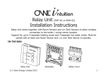
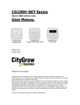
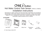
C-Stat 11-ZW | C-Stat 17-ZW
Installation Instructions
Wireless Programmable
Room Thermostat and ASR-ZW Receiver
Programmable room thermostats are widely recognised as one
of the best ways in which to control central heating. Horstmann
C-Stat programmable room thermostats have a large display
and intuitive user interface, making them easy to set up and use.
C-Stat uses a sophisticated time proportional integral (TPI)
algorithm for accurate temperature control and energy
efficiency. The C-Stat ZW is a wireless electronic battery
powered programmable room thermostat that uses
interoperable two-way RF mesh networking technology which
avoids the need for additional wiring or unsightly cable runs.
Installation and connection should only be carried out by a
suitable qualified person and in accordance with the current
edition of the IEE wiring regulations.
Warning: Isolate mains supply before commencing installation.
1
Installing the ASR-ZW receiver
The ASR-ZW receiver should be located as near as is
practical to the boiler or zone valve to be controlled, as
well as a convenient mains electricity supply. To remove
the wall plate from the ASR-ZW undo the two retaining
screws located in the underside, the wall plate should
now be easily removed. Once the wall plate has been
removed from the packaging please ensure the ASRZW is resealed to prevent damage from dust, debris etc.
The wall plate should be fitted with the retaining screws
located at the bottom and in a position which allows a
total clearance of at least 50mm around the ASR-ZW
receiver.
Direct Wall Mounting
Offer the plate to the wall in position where the ASR-ZW
is to be mounted and mark the fixing positions through
the slots in the wall plate. Drill and plug the wall, then
secure the plate into position. The slots in the wall plate
will compensate for any misalignment of the fixings.
Wall Box Mounting
The wall plate may be fitted directly on to a single gang
flush wiring box complying with BS4662, using two M3.5
screws. The receiver is suitable for mounting on a flat
surface only; it is not suitable for mounting on an
unearthed metal surface.
2
Electrical Connections
WARNING: ISOLATE THE MAINS SUPPLY BEFORE
COMMENCING INSTALLATION
As the C-Stat is a wireless product with no electrical connections
all electrical wiring will be made to the ASR-ZW receiver.
All necessary electrical connections should now be made. Flush
wiring can enter from the rear through the aperture in the
backplate.
The mains supply terminals are intended to be connected to the
supply by means of fixed wiring.
The receiver is mains powered and requires a 3 Amp fused spur.
The recommended cable size is 1.0mm².
The receiver is double insulated and does not require an earth
connection, an earth connection block is provided on the
backplate for terminating any cable earth conductors. Earth
continuity must be maintained and all bare earth conductors
must be sleeved. Ensure that no conductors are left protruding
outside the central space enclosed by the backplate.
ASR-ZW Receiver internal wiring diagram
Internal
Electronics
N
L
230V
50Hz
1
2
3
COMM OFF
4
ON
The receiver has Voltage Free contacts. A link between Live and
terminal 2 is required for mains Voltage applications.
3
Example circuit diagrams for typical boiler installations are
shown below. These diagrams are schematic and should be
used for guidance only.
Please ensure that all installations comply with the current IEE
regulations and the boiler manufacturer's installation
instructions.
For reasons of space and clarity not every connection has been
included and the diagrams have been simplified, for instance
some earth connections have been omitted.
Cylinder and Room Thermostat Key:
C= Common CALL= Call for heat or break on rise
SAT= Satisfied on rise N= Neutral
ASR Receiver
1
2
3
4
L
Mains
Supply
N
Remove link
if Fitted
E
E N
L
COMBINATION BOILER
TERMINALS
C-Stat ASR Receiver controlling typical combination boiler installation.
For precise termination connection information please refer to the boiler manufactures
instructions
4
Programmer
HOT
WATER
N L
MAINS
SUPPLY
CENTRAL
HEATING
OFF
ON
OFF
ON
ASR Receiver
N
L
E
C
N
1
C
CYL
STAT
CALL
ROOM
STAT
SAT CALL
MAINS
SUPPLY
SAT
2
3
4
N
L
E
N
PUMP
&
L BOILER
C-Stat ASR Receiver controlling a secondary heating zone on a fully pumped system
with existing programmer and two spring return valves with auxiliary switches
Programmer
HOT
WATER
N L
MAINS
SUPPLY
OFF
ON
N
L
E
CENTRAL
HEATING
ASR Receiver
C
CYL
STAT
CALL
OFF
ON
SAT
2
3
SAT
4
CALL
W
BL
0
GR
N
L
PUMP
&
BOILER
C-Stat ASR Receiver replacing a conventional room thermostat on a fully pumped
system with an existing programmer and 3 port mid-position valve.
5
Programmer
HOT
WATER
N L
MAINS
SUPPLY
OFF
ON
N
L
E
CENTRAL
HEATING
ASR Receiver
C
CYL
STAT
CALL
N
OFF
ON
SAT
2
4
CALL
3
SAT
L
PUMP
&
BOILER
C-Stat ASR Receiver replacing a conventional room thermostat on a fully pumped
system with existing programmer and two spring return valves with auxiliary switches
6
TPI Temperature control software
Thermostats using TPI (Time Proportional Integral) control
algorithms will reduce the temperature swing that normally
occurs when using traditional bellows or thermally operated
thermostats. As a consequence, a TPI regulating thermostat will
maintain the comfort level far more efficiently than any
traditional thermostat.
When used with a condensing boiler, the TPI thermostat will help
to save energy as the control algorithm allows the boiler to
operate in condensing mode more consistently compared to
older types of thermostat.
Ÿ For Gas boilers set the TPI setting to 6 cycles per hour (default
setting)
Ÿ For Oil boilers set the TPI setting to 3 cycles per hour
Ÿ For Electric heating set the TPI setting to 12 cycles per hour
To adjust this setting go to the SET UP MENU and select TPI
CYCLES
7
Fitting the C-Stat Programmable Room Thermostat
Before final installation it is advisable to commission the product
and ensure that the Thermostat and Receiver are
communicating satisfactorily. First install the 2 x AA batteries
provided making sure that they are fitted correctly as indicated
by the markings in the battery compartment on the front of the CStat. Once the thermostat and receiver are successfully 'paired'
the thermostat can be installed in its correct location. Please see
Z-Wave pairing instructions on page 9.
Avoid installing the C-Stat against or behind any large metal
surfaces which could interfere with the radio signals to and from
the ASR-ZW receiver. The C-Stat should be mounted on an
internal wall approximately 1.5 metres from floor level using the
wall plate provided and should be in a position away from
draughts, direct heat and sunlight. Ensure that there will be
enough space to allow easy access to the two retaining screws
located at the base of the wall plate.
1.5m
8
Before fixing the wall plate in position check to see that the
thermostat and receiver are still able to communicate
satisfactorily by turning the thermostat temperature up and
down to switch the ASR-ZW receiver on and off.
Offer the plate to the wall in the position where the C-Stat is to be
mounted and mark the fixing positions through the slots in the
wall plate. Drill and plug the wall, then secure the plate into
position. The slots in the wall plate will compensate for any
misalignment of the fixings.
Complete installation by swinging the C-Stat into position by
engaging with the lugs at the top of the wall plate before pushing
it carefully home into its plug-in terminal block.
Tighten the 2 captive screws on the underside of the unit.
Now ensure that the heating system is responding to the
ON/OFF commands from the C-Stat and explain its operation to
the householder before handing over the User Instructions.
9
Pairing the C-Stat ZW programmable room thermostat with
ASR-ZW receiver
The C-Stat uses the latest Z-Wave wireless communication
technology to give a reliable wireless link that should not suffer
from interference from other nearby devices. The device
comprises of a thermostat (C-Stat ZW) and its receiver (ASRZW). Pairing the devices on site ensures reliable
communication.
Follow these steps to ensure that the C-Stat programmable stat
will communicate satisfactorily with its receiver; this is best
carried out with the C-Stat held nearby the (powered) ASR-ZW
receiver.
The ASR-ZW receiver should be powered up with the network
button flashing red before following Procedure A on page 11.
If the red network button light does not flash red then please go
to Procedure B on page 12 before returning to Procedure A on
page 11.
HRT4
ASR-ZW
ON
OFF
Network
LED
Network
Button
Procedure A
1.
On the C-Stat programmable stat, Press ENTER twice
2.
Press '-' or '+' to select SETUP
3.
Press ENTER
4.
Press '-' or '+' to select SET UP Z-WAVE
5.
Press ENTER
6.
This will now show the sub menu available for the Z-Wave
wireless communication settings
7.
Select INCLUDE NODE / RECEIVER
8.
Press ENTER
9.
INCLUDING will appear under the INCLUDE NODE
heading.
10. Press and hold the network button on the ASR-ZW
Receiver until the flashing red light turns to a flashing green
light followed quickly by a solid red light
11. RECEIVER INCLUDED will now appear in the display of
the C-Stat. Press BACK and the antenna icon on the top left
had corner of the display will show it is active with radio
waves
12. The C-Stat and ASR-ZW Receiver are now 'paired'. The
Receiver should receive ON/OFF commands from the CStat wirelessly.
Check this by turning the temperature on the C-Stat up and
down to see that the ASR-ZW receiver responds
accordingly with a green light for ON and a red light for OFF.
11
Procedure B
1.
2.
3.
4.
5.
6.
7.
8.
9.
10.
11.
12.
13.
14.
15.
16.
17.
12
On the C-Stat programmable stat, Press ENTER twice
Press '-' or '+' to select SETUP
Press ENTER
Press '-' or '+' to select SET UP Z-WAVE
Press ENTER
Press '-' or '+' to select NETWORK RESET
Press ENTER
Press ENTER again to confirm and NETWORK RESET
COMPLETE will appear on the display
Press BACK to go back to SET UP Z-WAVE
Press ENTER
Press '-' or '+' to select EXCLUDE NODE / RECEIVER
Press ENTER
Go to the Powered ASR-ZW receiver, press and hold the
network button
EXCLUDING will appear on the display of the C-Stat
When completed NODE / EXCLUDED will appear on the
display.
The red network light on the ASR-ZW will start flashing
Once the red light is flashing follow Procedure A on page
11
Installer Settings
There are a number of 'Installer Settings' that should be set on
installation.
These can be found under the 'SET UP MENU' on page 15 of
the user instructions.
Clock Format
AM/PM or 24 Hour clock display - Default
setting AM/PM
Daylight saving
On or Off - Default setting ON for UK Market
Standby temperature
Frost protection setting – Default setting 5°C
Upper and Lower
Default settings 30°C and 5°C
Temperature limits
TPI Cycles
This setting will change according to the
type of boiler being used - Default setting 6
For Gas boiler this setting should be 6
cycles per hour
For Oil boilers this setting should be 3
cycles per hour
For Electric panel heaters this should be 12
cycles per hour
Optimum Start
On or Off – Default setting Off
The TPI Cycles setting and Optimum Start settings should be
carefully set on installation as this will affect system performance.
13
Resetting the C-Stat
Electronic equipment can in some circumstances be affected by
electrical interference.
If the display becomes frozen or scrambled simply press both
the BACK and ENTER button simultaneously.
This will cancel all settings made and return to the factory default
settings.
BACK
14
ENTER
Specification – C-Stat 11-ZW | C-Stat 17-ZW
Thermostat
Power Supply
Contact type
Wiring configuration
Temperature differential
Temperature accuracy
Standards
Dimensions (WxHxD)
Weight
Enclosure
Ingress protection
Pollution degree
Insulation class
Temperature range
Transmitter Frequency
Receiver Category
Power Class
Receiver
Power Supply
Contact Type
Contact Current Rating
Insulation Class
Rated Impulse Voltage
Pollution Degree
Enclosure Protection
Dimensions
15
2 x AA Batteries
Micro-disconnection
Voltage free c/o contacts (SPDT)
0.5°C
+/- 0.5°C to 21°C
BS EN 60730-2-9
120mm x 100mm x 26.5mm
0.3kg (approx)
Flame retardant thermoplastic
IP30
Degree 2
Class II (Double Insulated)
0°C to 40°C
868 MHZ
Category 3
Class B
230V AC 50Hz
Micro-disconnection
Voltage Free
3 (1) Amps 230V AC
Double Insulated
Cat 2 – 2500V
Degree 2
Flame retardant thermoplastic
86 x 86 x 36.25mm
Secure Controls (UK) Limited
South Bristol Business Park,
Roman Farm Road, Bristol BS4 1UP
E-mail: [email protected]
Web site: www.horstmann.co.uk
16
Part Number P84875 Issue 1