1
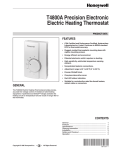
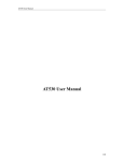
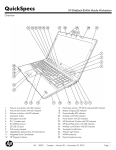
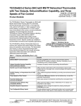
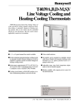
T4098A,B
Deluxe Electric Heat Thermostats
PRODUCT DATA
FEATURES
• Controls both fan-forced and baseboard electric
heaters.
• Temperature-responsive, vapor-filled dual diaphragm
sensing element provides 2°F (1°C) sensitivity with
minimum droop.
• Replaces virtually all standard wall-mounted line
voltage thermostats.
• Includes long-lasting Micro Switch™ mechanism.
• Color-coded leads allow easy installation.
• Protective cover door opens to provide access to
setpoint knob.
• Attractive sloped faceplate allows easy viewing of
temperature.
GENERAL
• Classic styling.
The T4098A,B Deluxe Electric Heat Thermostats provide high
performance line voltage direct control of resistance-rated
electric heating equipment.
CONTENTS
General ...............................................................................
Features ..............................................................................
Specifications ......................................................................
Ordering Information ...........................................................
Installation ...........................................................................
Settings and Adjustments ...................................................
Checkout .............................................................................
Operation ............................................................................
Copyright © 1996 Honeywell Inc. •
• All Rights Reserved
1
1
2
2
3
4
6
6
68-0146-3
T4098A,B DELUXE ELECTRIC HEAT THERMOSTATS
Electrical Ratings (Noninductive Resistive Loads):
22A at 120/208/240 Vac, 60 Hz.
19A at 277 Vac, 60 Hz.
SPECIFICATIONS
IMPORTANT
The Specifications given in this publication do not
include normal manufacturing tolerances. Therefore,
this unit may not exactly match the listed
specifications. Also, this product is tested and
calibrated under closely controlled conditions, and
some minor differences in performance can be
expected if those conditions are changed. For exact
engineering specifications, contact your Honeywell
sales representative.
Wiring Connections:
6 in. (150 mm) leads suitable for connecting to aluminum
wiring if approved special service CO/ALR connectors are
used.
Sensing Element:
Vapor-filled dual diaphragm.
Setpoint Adjustment:
Knurled knob on front of thermostat.
TRADELINE® Models
Differential:
2°F (1°C), nonadjustable.
TRADELINE® models are selected and packaged to provide
ease of stocking and handling and also maximum
replacement value. See Table 1 for TRADELINE® model
specifications.
Dimensions:
See Figs. 1 and 2.
Table 1. Thermostat Specifications.
Model
Number Switching
Temp.
Rating
F° (C°)
Mounting:
Mount directly on vertical 2 x 4 in. outlet box, or on 4 x 4 in.
outlet box using ring adapter (ordered separately).
Finish
Includes
50° to 90°
T4098A Spst;
(10° to 30°)
makes
single line
break on
temperature
fall.
Classic
beige or
Premier
White™
Cover
thermometer,
temperature
range stops,
and locking
cover.
50° to 90°
T4098B Dpst;
(10° to 30°)
makes
double line
break with
setting knob
in OFF
position.
Classic
beige or
Premier
White™
Cover
thermometer,
temperature
range stops,
and locking
cover.
Approvals:
Underwriters Laboratories Listed: File No. E47434, Guide
No. XAPX.
Canadian Standards Association Listed: File No. LR1322.
Canadian Standards Association Performance Certified:
C273.4.
Accessories:
272804A Range Stop and Locking Screw Assembly. Includes
locking cover screws, Tinnerman clips, wrench, and range
stops—two plastic pins to insert inside cover for fieldselection of minimum and maximum temperature settings.
ORDERING INFORMATION
When purchasing replacement and modernization products from your TRADELINE® wholesaler or distributor, refer to the
TRADELINE® Catalog or price sheets for complete ordering number or specify.
1. Model number.
2. Switching.
3. Type of finish.
If you have additional questions, need further information or would like to comment on our products or services, please write or
phone:
1. Your local Honeywell Home and Building Control Sales Office (check white pages of your phone directory).
2. Home and Building Control Customer Relations
Honeywell, 1885 Douglas Drive North
Minneapolis, Minnesota 55422-4386
In Canada—Honeywell Limited/Honeywell Limitée, 35 Dynamic Drive, Scarborough, Ontario M1V 4Z9. International sales and
service offices in all principal cities of the world. Manufacturing in Australia, Canada, Finland, France, Germany, Japan, Mexico,
Netherlands, Spain, Taiwan, United Kingdom, U.S.A.
68-0146—3
2
T4098A,B DELUXE ELECTRIC HEAT THERMOSTATS
FRONT VIEW
SIDE VIEW
CAUTION
2-5/8 (67)
1.
Disconnect power supply to prevent electrical
shock or equipment damage.
If connecting with aluminum conductors, use CO/
ALR solderless wire connectors to avoid fire
hazard.
Do not remove thermostat cover until wiring is
complete to avoid damaging the sensing element.
2.
3.
2-1/8
(54)
4-1/2
(115)
4-1/2
(115)
Location
Install a vertical outlet box that is used to mount the
thermostat about 5 ft (1.5m) above the floor in an area with
good air circulation at room temperature.
2-7/8 (73)
1-3/4
(45)
1
(25)
Do not install the thermostat where it may be affected by:
— drafts or dead spots behind doors, in corners or under
cabinets.
— hot air from convectors.
— radiant heat from sun or appliances.
— concealed pipes and chimneys.
— unheated (uncooled) areas such as an outside wall
behind the thermostat.
M5790
Fig. 1. T4098 dimensions in in. (mm).
RECYCLING NOTICE
If this control is replacing a control that contains
mercury in a sealed tube, do not place your old
control in the trash.
Wiring and Mounting
CAUTION
Contact your local waste management authority for
instructions regarding recycling and the proper
disposal of an old control containing mercury in a
sealed tube.
1.
2.
Handle the thermostat with care to avoid
damaging the sensing element or control.
Use a separate limit control in the heating
appliance.
L2
T4098A
INSTALLATION
1
When Installing this Product…
L1
(HOT)
1. Read these instructions carefully. Failure to follow these
instructions could damage the product or cause a
hazardous condition.
2. Check the ratings on the product to make sure the
product is suitable for your application.
3. Installer must be a trained, experienced service
technician.
4. After installation is complete, check out product
operation as provided in these instructions.
2
3
L1
T1
4
ELECTRIC
HEATER
WARNING
1
POWER SUPPLY. PROVIDE DISCONNECT MEANS AND OVERLOAD
PROTECTION AS REQUIRED.
HIGH VOLTAGE CONTROL.
ELECTRICAL SHOCK HAZARD.
Follow local codes and ordinances when installing this
thermostat. Improper handling can cause serious
injury or death.
2
USE SPECIAL SERVICE CO/ALR SOLDERLESS CONNECTORS
WHEN CONNECTING ALUMINUM CONDUCTORS OR A FIRE
HAZARD MAY RESULT.
3
BREAKS AND REMAKES BELOW -31°F(-35°C); NORMALLY
THERMALLY ACTIVATED. BREAKS ON A TEMPERATURE RISE;
MAKES ON A TEMPERATURE FALL.
4
USE A SEPARATE LIMIT CONTROL IN THE HEATING APPLIANCE.
M5813B
Fig. 2. Typical wiring connections for T4098A.
3
68-0146—3
T4098A,B DELUXE ELECTRIC HEAT THERMOSTATS
2
L2
T4098B
1
L1
(HOT)
WALL
6
3
L1
L2
RED WIRE
THERMOSTAT
BASE
5
T1
T2
4
ELECTRIC
HEATER
1
POWER SUPPLY. PROVIDE DISCONNECT MEANS AND OVERLOAD
PROTECTION AS REQUIRED.
2
USE SPECIAL SERVICE CO/ALR SOLDERLESS CONNECTORS
WHEN CONNECTING ALUMINUM CONDUCTORS OR A FIRE
HAZARD MAY RESULT.
3
BREAKS AND REMAKES BELOW -31°F(-35°C); NORMALLY
THERMALLY ACTIVATED. BREAKS ON A TEMPERATURE RISE;
MAKES ON A TEMPERATURE FALL.
4
USE A SEPARATE LIMIT CONTROL IN THE HEATING APPLIANCE.
5
BREAKS AT POSITIVE OFF ONLY; NOT THERMALLY ACTIVATED.
6
DO NOT CONNECT GROUNDED CONDUCTORS (NEUTRAL) ON
120V OR 277V CIRCUITS. INSULATE AND TAPE, OR CUT OFF
RED WIRES IF UNUSED.
M5814B
OUTLET
BOX
MOUNTING
SCREWS (2)
M5794
Fig. 4. Mounting thermostat to outlet box.
New Applications
� Disconnect the power supply to prevent electrical shock
or equipment damage. All wiring must comply with local
electrical codes and ordinances.
� Run the line voltage wiring to the thermostat location.
� Do not remove the T4098 Thermostat Cover. Using wire
connectors approved for No. 12 wires, make line
voltage connections directly to the leadwires on the
thermostat. See Figs. 2 and 3 for typical wiring
connections.
� Prebend and push the solid wires into the outlet box.
� While holding the thermostat base with one hand, use
the other hand to remove the thermostat cover by
grasping the bottom cover edge and pulling outward
away from the thermostat base.
� Mount the thermostat on the outlet box as shown in
Fig. 4. Secure the thermostat by tightening the two
mounting screws.
Fig. 3. Typical wiring connections for T4098B.
IMPORTANT
If locking cover feature is desired, insert the locking
cover clip in the thermostat base before mounting
the thermostat on the wall. See Fig. 7.
Replacement Applications
� Disconnect power to thermostat to prevent electrical
shock or equipment damage. All wiring must comply
with local electrical codes and ordinances.
� Remove the old thermostat from the wall; be careful not
to damage the wiring insulation.
� Check the old wire insulation for cracks, nicks or fraying.
Apply approved electrical tape to insulate wires or
replace wires as necessary.
� Do not remove T4098 Thermostat Cover. Using wire
connectors approved for No. 12 wires, make line
voltage connections directly to the leadwires on the
thermostat. See Figs. 2 and 3 for typical wiring
connections.
� Prebend and push the solid wires into the outlet box.
� While holding the thermostat base with one hand, use
the other hand to remove the thermostat cover by
grasping the bottom cover edge and pulling outward
away from the thermostat base.
� Mount the thermostat on the outlet box as shown in
Fig. 4. Secure the thermostat by tightening the two
mounting screws.
68-0146—3
SETTINGS AND ADJUSTMENTS
Calibration
The T4098 Thermostats are calibrated at the factory using
precise instruments under closely controlled conditions.
Recalibration should not be necessary. Allow the thermostat
to operate for several hours before checking the calibration.
The T4098 Thermostat vapor-filled dual diaphragm sensing
element is affected by barometric pressure and altitude.
Temperature deviations of 1°F (0.5°C) are normal. If the
thermostat is mounted in a suitable location (as instructed in
the Location section) and still appears out of calibration,
check calibration as follows.
4
T4098A,B DELUXE ELECTRIC HEAT THERMOSTATS
Check Calibration
THERMOSTAT
BASE
� Turn the setting knob clockwise until the switch makes
(clicking sound). The heating equipment and fan start.
� No recalibration is necessary if the thermostat switch
makes with the thermostat setting at the same
temperature as indicated on the thermometer.
� If the thermostat setting differs from the thermometer,
record the temperature difference and recalibrate as
instructed in the Recalibration Procedure section.
DUAL-DIAPHRAGM
SENSING ELEMENT
Recalibration Procedure
� Note the temperature difference between the
temperature setting and the thermometer.
� Remove the thermostat cover.
� With the thermostat cover removed, note the location of
the temperature setting knob.
� Remove the clear plastic knurled setting knob. See
Fig. 5.
� Turn the temperature setting dial the required number
of degrees for calibration (so thermostat temperature
setting and thermometer are the same).
� Replace the knob on the setting dial.
� Replace the thermostat cover and recheck the
calibration.
SETTING DIAL
CLEAR PLASTIC
KNURLED
SETTING KNOB
Setting Range Stops
Use the range stops (included) to limit the maximum and
minimum temperatures that may be set.
� Move the thermostat setting knob to the desired
maximum temperature.
� Remove the thermostat cover.
� Adjust the knob indicator tab between the range stop
positions to prevent interference.
� Insert the range stop pins in the desired positions on
the back of the thermostat cover. See Fig. 6.
� Make sure pins are completely seated before replacing
the thermostat cover.
� Replace the thermostat cover and check the range
stops.
M5793
Fig. 5. Calibrating thermostat.
INSIDE VIEW
OF THERMOSTAT
COVER
70 20
28
80
2
1
50
2
Locking Cover
4
INSERT PINS INTO
TEMPERATURE
STOP POSITIONS.
F
60
C 16
The thermostat cover may be locked using the locking cover
screws included. Locking the cover prevents unauthorized
tampering of the thermostat temperature setting.
� Remove the thermostat cover.
� Insert the locking cover clip (included) into the slot on
the back of thermostat base as shown in Fig. 7.
� Using an Allen wrench, insert the locking cover screw
into the clip. Secure the screw in place until it is flush
with the thermostat base.
M5800
Fig. 6. Setting range stops.
5
68-0146—3
T4098A,B DELUXE ELECTRIC HEAT THERMOSTATS
CHECKOUT
THERMOSTAT
BASE
LOCKING
COVER
CLIP
IMPORTANT
Make sure that all wiring connections are secure
before beginning checkout.
5
0
THERMOSTAT
COVER
After thermostat installation is complete, check operation as
follows:
� Move the thermostat setting knob clockwise until the
switch makes (clicking sound); the electric heater starts.
� Move the setting knob fully counterclockwise; the switch
breaks and the electric heater stops.
� Allow the thermostat to operate for several hours to
determine the appropriate temperature setting. Adjust
the setting as necessary.
7
0
9
0
60
50
70
80
90
°F
OPERATION
LOCKING
COVER SCREW
The T4098 Thermostat provides precise temperature control
of resistance-rated electric baseboard heating equipment with
minimum droop. The T4098 controls room temperature within
2°F (1°C), regardless of the load of the baseboard heater.
ALLEN WRENCH
The vapor-filled dual diaphragm sensing element is more
sensitive to temperature changes than a bimetal sensor. This
accuracy, usually associated with low voltage thermostats, is
now available for line voltage control.
M5799
Fig. 7. Locking cover.
Electric heat thermostats are often affected by the heat
generated in the control. Temperature control points may vary
or droop 2° to 4°F (1° to 3°C) depending on the load demand;
however, temperature settings are adjusted to provide offset.
The T4098 provides precise control with minimum droop. This
allows better control of room temperatures from day-to-night
and season-to-season while saving energy.
68-0146—3
6
T4098A,B DELUXE ELECTRIC HEAT THERMOSTATS
7
68-0146—3
T4098A,B DELUXE ELECTRIC HEAT THERMOSTATS
Home and Building Control
Honeywell Inc.
1985 Douglas Drive North
Golden Valley, MN 55422
68-0146—3 C.H. Rev. 4-96
Home and Building Control
Honeywell Limited-Honeywell Limitée
155 Gordon Baker Road
North York, Ontario
M2H 2C9
Printed in U.S.A.
Printed on recycled paper containing at
least 10%8post-consumer paper fibers.
Helping You Control Your World
www.honeywell.com/building/components