1
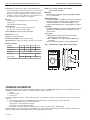
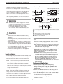
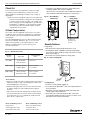
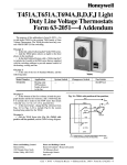
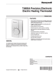
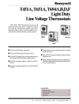
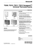
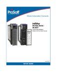
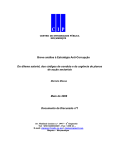
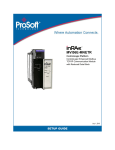
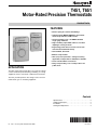
T451, T651
Motor-Rated Precision Thermostats
PRODUCT DATA
FEATURES
• Deluxe styling for commercial buildings.
• Industrial grade MICRO SWITCH™ mechanism
rated 1/2 hp inductive, 5 kW resistive.
• Vertical mounting on 2” x 4” NEMA-standard
single-gang outlet box.
• High-sensitivity, vapor-filled stainless steel dual
diaphragm sensing element.
• Engineering plastic base to isolate sensor from
switch heat and minimize droop.
• CSA Certified, UL Listed.
• Altitude compensation.
• 44°F (7°C) “frost protection” setting for heating
application, independent of calibration or altitude.
• Color-coded leadwire connections.
APPLICATION
• Range stops/locking cover security features for
public areas.
The T651 thermostat provides direct, accurate line voltage
control of inductively-rated heating, ventilating, or cooling
equipment used in commercial or industrial environments.
The T451 provides precision line voltage control of motorrated electric, gas or oil heating equipment.
Contents
Specifications . . . . . . . .
Ordering Information . . .
Installation. . . . . . . . . . .
Setting and Adjustment.
CL 4-01 • © Honeywell Limited/Limitée 2001
.
.
.
.
.
.
.
.
.
.
.
.
.
.
.
.
.
.
.
.
.
.
.
.
.
.
.
.
.
.
.
.
.
.
.
.
.
.
.
.
.
.
.
.
.
.
.
.
.
.
.
.
.
.
.
.
.
.
.
.
.
.
.
.
.
.
.
.
.
.
.
.
.
.
.
.
.
.
.
.
.
.
.
.
.
.
.
.
.
.
.
.
.
.
.
.
.
.
.
.
2
2
3
4
95C-10903-1
T451, T651 MOTOR-RATED PRECISION THERMOSTATS
SPECIFICATIONS • ORDER INFORMATION
Finish: Classic beige-and-light gold standard.
White models available.
Important: The specifications given in this publication do
not include normal manufacturing tolerances. Therefore this
unit may not exactly match the listed specifications . This
product is tested and calibrated under closely controlled
conditions, and some minor differences in performance can
be expected if these conditions are changed.
Mounting:
Mounts directly on vertical, single-gang NEMA Standard
(2” x 4”) electrical box.
Wiring Connections:
6” (150 mm) leadwires suitable for connecting to aluminum
conductors wiring if used with approved special service
CO/ALR solderless wire connectors. Leadwires colorcoded red for heating, blue for cooling, black for common.
Models:
T451A SPST and T451B DPST (with positive off) for
heating only.
T651A SPDT for heating/cooling.
Control Range:
44 - 86°F (7 - 28°C) for models T451A, T651A.
50 - 86°F (10 - 28°C) for model T451B.
Approvals:
Canadian Standards Association Certified; File No. LR1322
Performance Certified for electric heating per C273.4A.
UL file E47434.
Sensing Element: Vapor-filled dual diaphragm.
Accessories:
272804A Range stops and cover locking assembly
(included in selected models only).
220213 Wallplate, covers old T451/T651 (1000 series)
wall marks.
TG511 Thermostat guard for security and protection.
Differential: 2°F (1°C)
Droop: 2°F @ mid load range.
Barometer Sensitivity: 1/8°F/”wc (0.3°C/kPa).
Thermometer: 50 - 90°F (10 - 30°C) in 10°F (5°C) increments.
Electrical Ratings:
50/60Hz
120 V
208V
240V
Full Load
9.8A
5.6A
4.9A
4.2A
Locked Rotor
58.8A
33.6A
29.4A
25.2A
Pilot Duty
Resistive
Heating Only
Fig. 1 — Dimensions of T451, T651 in inches (mm):
277V
125 VA
22A Non Inductive
2.5kW
4.5kW
19ANI
5kW
ORDERING INFORMATION
When purchasing replacement and modernization products from your TRADELINE® wholesaler or your distributor, refer to the
TRADELINE catalog or price sheets for complete ordering number, or specify:
1. Model
2. Electrical load(s)
3. Accessories.
If you have additional questions, need further information, or would like to comment on our products or services, please write
or phone:
1. Your local Honeywell Home and Building Control Sales Office (check white pages or phone directory).
2. Home and Building Control Customer Satisfaction
Honeywell Inc., 1885 Douglas Drive North.
Minneapolis, MN 55422 (612) 951-1000
3. In Canada — Honeywell Limited, 35 Dynamic Drive, Toronto, ON M1V 4Z9, 1-800-405-9835.
International Sales and Service Offices in all principal cities of the world. Manufacturing in Australia, Canada, Finland, France,
Germany, Japan, Mexico, Netherlands, Spain, Taiwan, United Kingdom, U.S.A.
2
95C-10903-1
T451, T651 MOTOR-RATED PRECISION THERMOSTATS
INSTALLATION
Fig. 2 — Wiring connections
WHEN INSTALLING THIS PRODUCT:
1. Read these instructions carefully. Failure to follow
instructions can damage product or cause a hazardous
condition.
2. Check ratings given in instructions and on product to
make sure product is suitable for your application.
3. Make sure installer is a trained, experienced service
technician.
4. After completing installation, use these instructions to
check out product operation.
T451A (Heat only)
T451B (Heat only with positive off)
To
Heating
Load
To
Heating
Load
T651A (Heat only)
T651A (Cool only application)
To
Heating
Load
To
Cooling
Load
! WARNING
This thermostat is a line voltage (120 to 277 Vac)
control. Do not install it unless you are completely
familiar and competent with home wiring.
If improperly handled there can be a risk of
240 volt electric shock hazard which may cause
serious injury or death.
T651A (Heat–Cool application)
To
Heating
Load
To
Cooling
Load
! CAUTION
1. Disconnect power supply before making wiring
connections to prevent electrical shock or equipment
damage.
2. All wiring must comply with national and local codes
and ordinances.
3. When using aluminum conductors, all wiring connections to this thermostat must be made to the factory
installed leadwires using approved CO/ALR solderless
connectors. A fire hazard may result otherwise.
4. To avoid handling the sensing element, do not remove
thermostat cover until wiring is completed.
5. Thermostats are designed for use with appliances
having a limit control.
1
Power supply; provide disconnect means and overload protection as required.
2
Breaks on Positive Off.
3
Exposed unused wires must be properly insulated.
4
Contact makes Black to Red on temperature fall;
Black to Blue on temperature rise.
4. Pre-bend and push leadwires into the electrical junction
box.
5. Hold the thermostat base with one hand and remove the
thermostat cover by grasping two sides of the cover and
pulling outward.
NOTE: If locking cover feature is desired, insert the locking
cover clip in the thermostat base BEFORE mounting the
thermostat on the wall (see Fig. 7).
6. Using the screwdriver, secure the thermostat to the box by
tightening the two mounting screws. Handle thermostat
with care. Excessive pressure may damage the control
knob or sensing element.
IMPORTANT: Before mounting the thermostat, turn the
setting dial to the mid-position (indicator pointing to the
top of the thermostat): this will prevent damage to the
dial stop if the dial is accidentally turned by the screw
driver when the top mounting screw is tightened. Do
NOT press on diaphragm, diaphragm lever arm or
setpoint knob to seat thermostat on the box : thermostat
will be damaged.
New Installations
1. Install a single-gang electrical box oriented vertically about
4’ to 5’ (1.5 m) above the floor on an inside wall or pillar
where the thermostat will be subjected to typical room
temperature.
NOTE: To sense temperature properly, the thermostat
must be placed away from concealed warm or cold water
pipes, air ducts, or drafts from hallways, fireplaces or
stairways. Do not place thermostat above convectors or
in the flow from supply fans. Ideally, a thermostat should
be close to the return air path to effectively measure
average room temperature.
2. Wire installation in an approved fashion.
NOTE: T651A and T451A do not feature a Positive Off
setting, and may not be used as a disconnect switch.
3. Leave cover on the thermostat while making wiring
connections. Use solderless connectors approved for the
type, number and gauge of wires being joined.
Replacement Applications
1. Disconnect power supply before making wiring
connections to prevent electrical shocks or equipment
damage. All wiring must comply with applicable codes
and standards.
2. Remove the old thermostat from the wall, taking care not
to damage the wiring insulation.
3. Check the old insulation for cracks, nicks or fraying. Apply
certified electrical tape where necessary to insulate wires,
or replace the wires in an approved fashion.
4. Complete installation following steps 3 to 6 in the New
Installations section.
Connect as per Fig. 2 for the appropriate application.
3
95C-10903-1
T451, T651 MOTOR-RATED PRECISION THERMOSTATS
INSTALLATION
Check Out
4. Install the cover. Wait five minutes to let the thermostat
thermally stabilize and re-check calibration.
Do not assume a thermostat is out of calibration until it has
been installed and allowed to operate for several hours.
Turn on power. Raise the temperature setting to energize
the heating contact and break the cooling contact. The
HVAC equipment should begin heating or stop cooling, as
appropriate.
NOTE: For T451A and T651A models only, the thermostat
will call for heat (disable cooling) when the setpoint dial
is at full counter-clockwise position. This setting is the
phase change point of the diaphragm’s vapor fill and is
independent of calibration. To de-energize the load(s),
turn off power at the circuit breaker panel, or add a
separate disconnect switch.
Fig. 4 — Recalibrating
Thermostat
Fig. 5 — Installing
Range Stops
Altitude Compensation
T451, T651 units are calibrated at the factory for accuracy
at 500 feet above sea level. No recalibration is needed if the
switch operates at the same temperature indicated on the
thermometer.
The vapor-filled diaphragm sensor is affected by barometric
pressure and altitude. Deviations up to ± 1°F (1/2°C) are
within normal operation. Control point drops 2°F every
1000 ft. (1°C/300 m) above sea level. See Fig. 3 for
recommended action.
Insert pins into
temperature stop
positions
Security Features:
Range Stops
1. Set thermostat to desired setpoint. Remove cover.
2. Install plastic dowels supplied (or purchased separately)
into minimum and/or maximum range stop holes on inside
back of cover (Fig. 5).
3. Re-install cover. Check operation of range stops.
Fig. 6 — Cover Locking Kit
Fig. 3 — Altitude Correction
Elevation
(in feet)
Recommended
Action
Typical City
0 to 2000
Toronto, Ontario
Phoenix, Arizona
2000 to 4000
Las Vegas, Nevada
Calgary, Alberta
Move clockwise
2 to 3 marks
4000 to 6000
Denver, Colorado
Salt Lake City, Utah
Move clockwise
4 to 5 marks
Leave as is
To Recalibrate
1. Remove cover. Set the tab on setpoint knob to the leftmost
radial mark visible on top of the triangular arm that holds
the dual diaphragm sensor (Fig. 4).
2. Without rotating the knob, remove it from the thermostat
by pulling straight out, while holding the base against
the wall.
3. Now, rotate the removed setpoint knob clockwise by the
amount of temperature error. Each mark on the triangular
arm represents 2°F (1°C) of adjustment. Snap the knob
back onto the setpoint cam.
Home and Building Control
Honeywell Inc.
1985 Douglas Drive North
Golden Valley, MN 55422
95C-10903-1
Locking Cover
1. Remove cover by pulling straight out.
2. Insert Tinnerman Speed Nut®s into slots top and bottom of
thermostat base.
3 Drive Allen screw into Speed Nut until head is flush with
outside edge of thermostat base.
4. Re-install cover. Lock by backing out Allen screw until
screw body protrudes through cover hole. To unlock cover,
drive Allen screw into thermostat base.
Home and Building Control
Honeywell Limited-Limitée
35 Dynamic Drive
Toronto, ON M1V 4Z9
4