1
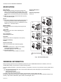
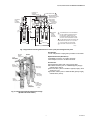
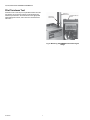
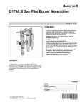
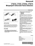
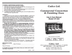
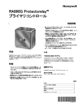
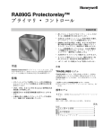
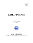
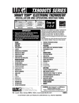
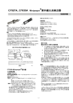
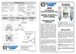
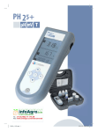
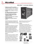
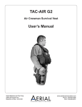
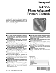
Q179A,B Gas Pilot Burner
Assemblies
PRODUCT DATA
GENERAL
Q179A,B Gas Pilot Burner Assemblies use the flame
rectification principle to prove the flame. Q179A,B are used in
conjunction with a suitable electronic flame safeguard control
on industrial or commercial gas and gas pilot ignited oil
burners.
FEATURES
• Q179A is a gas pilot assembly with a flame electrode
(rod) and ignition electrode, making it suitable for
applications requiring an interrupted or intermittent
electrically ignited gas pilot burner.
• Q179A1183 is an “I” port burner with an ignition
electrode (spark) only.
• Q179B has only the flame electrode and is suitable for
use in continuous pilot applications.
• Primary aerated type burner is equipped with stainless
steel fins that provide the proper flame rod area to
ground area ratio for maximum flame signal and flame
stabilization.
• Stainless steel electrode(s) are mounted in ceramic
insulators, which permit electrode adjustment.
Contents
General .............................................................................
Features ...........................................................................
Ordering Information ........................................................
Specifications ...................................................................
Installation ........................................................................
Checkout ..........................................................................
60-2032-05
1
1
2
2
4
5
Q179A,B GAS PILOT BURNER ASSEMBLIES
SPECIFICATIONS
Mounting Dimensions:
See Fig. 2.
Model Number:
Q179A—Gas pilot assembly with ignition and flame electrodes. Use with intermittent or interrupted ignition. Ignition
electrode is for use with 6,000V grounded secondary-ignition transformer. (Q179A1183 has ignition electrode [spark]
only.)
Q179B—Gas pilot assembly with flame electrode (rod) only.
Use with continuous pilot.
Maximum Temperature:
See Fig. 3.
E
Burner:
Primary aerated. Stainless steel fins provide proper flame contact area to ground area. Flame electrode and ground
bracket are furnished with each tip. Available tips are illustrated in Fig. 1, and listed in Table 1.
A
45° LEFT
HAND "ELL"
"I" PORT
Mounting Means:
Bracket has holes for side mounting and two lugs for end
mounting.
F
"T" PORT
G
45° "Y" PORT
H
45° "T" PORT
1
Type of Gas:
Natural; for LP gas, order LP orifice separately (see
Accessories).
B
45° "I" PORT
Gas Consumption:
Approximately two cu ft/hr.
Electrodes:
Stainless steel, maximum temperature 1750°F (954°C).
Electrode Insulator(s):
Ceramic.
D
45° RIGHT HAND "ELL"
Electrical Connector:
Rajah connector (both male and female supplied).
Approvals:
Underwriters Laboratories Inc. listed, File No. MP268;
Industrial Risk Insurers acceptable;
CSA certified, Master File No. LR-95329-1;
Factory Mutual approved;
American Gas Association certified, No. G140.401.
1
NOTE THAT GROUND PRONG
IS CUT OFF CLOSE TO BASE.
M5007
Fig. 1. Pilot tip assembly styles.
ORDERING INFORMATION
When purchasing replacement and modernization products from your TRADELINE® wholesaler or distributor, refer to the
TRADELINE® Catalog or price sheets for complete ordering number.
If you have additional questions, need further information, or would like to comment on our products or services, please write or
phone:
1. Your local Honeywell Automation and Control Products Sales Office (check white pages of your phone directory).
2. Honeywell Customer Care
1885 Douglas Drive North
Minneapolis, Minnesota 55422-4386
In Canada—Honeywell Limited/Honeywell Limitée, 35 Dynamic Drive, Toronto, Ontario M1V 4Z9.
International Sales and Service Offices in all principal cities of the world. Manufacturing in Australia, Canada, Finland, France,
Germany, Japan, Mexico, Netherlands, Spain, Taiwan, United Kingdom, U.S.A.
60-2032—05
2
Q179A,B GAS PILOT BURNER ASSEMBLIES
LOCATION OF
OPTIONAL
THERMOCOUPLE
FLAME ELECTRODE
3
GROUND BRACKET
IGNITION ELECTRODE
(ON Q179A ONLY)
MOUNTING
EARS
FOR END
MOUNTING
1-1/2
(38)
ELECTRODE
INSULATORS
CLAMP SCREW
INSULATOR
BRACKET
2
1-5/16
(33)
4-7/64
(104)
7/32
(6)
7/32 (6)
1
MOUNTING
HOLES 7/32 DIA.
FOR SIDE
MOUNTING
13/32
(10)
1-3/16 (30)
13/32
(10)
1-11/16 (43)
1-29/32 (48)
3 (74)
1
THIS DIMENSION WILL VARY DEPENDING
ON THE FLAME ELECTRODE AND INLET
FITTING USED. FORMATION OF THE
FLAME ELECTRODE AND GROUND FINS
WILL VARY WITH THE BURNER TIP USED.
2
GAP BETWEEN IGNITION ELECTRODE AND
BURNER TIP MUST BE 1/16 TO 3/32 INCH.
3
Q179A1183 DOES NOT HAVE FLAME
ELECTRODE OR GROUND BRACKET.
M24193
Fig. 2. Approximate mounting dimensions in inches. (mm) and arrangement of parts.
FLAME
ELECTRODE
1750F (954C)
GROUND
SHIELD
1300F (704C)
Inlet Fittings:
1/4 inch compression coupling factory-installed on all models.
Q179A
Replacement Parts (See Table 1):
37356 Rajah Connector—for ignition electrode.
104312 Rajah Connector—for flame electrode.
PILOT
BURNER TIP
1500F (816C)
Accessories:
High temperature (higher than 125°F [52°C]) cable:
Flame Rod Lead wire—part no. R1298020 (specify length)
rated at 400°F (204°C).
Ignition Lead wire—part no. R1061012 (specify length), rated
at 350°F (177°C).
High Tension Cable—part no. 32004766-003 (specify length),
rated at 482°F (250°C).
INSULATOR
1050F (566C)
IGNITION
ELECTRODE
1750F (954C)
PILOT
ORIFICE
780F (416C)
IGNITION
CONNECTOR
750F (399C)
FLAME
ELECTRODE
CONNECTOR
750F (399C)
M7859
Fig. 3. Component maximum temperature ratings.
(Q179A1126 model shown)
3
60-2032-05
Q179A,B GAS PILOT BURNER ASSEMBLIES
Table 1. Additional Q179A, B Replacement Parts
Orifice
Assembly Tip Style
Tip
I
Natural Gas
395390-25a
45° I
105064A
Flame Rod and Insulator
Assembly
LP Gas
395390-13b
133448A
395390-25a
45° RH
395390-25a
45° LH
395390-25a
T
395390-28c
45° Y
395390-28c
45° T
395390-28c
Large I
395390-25a
133451A
133448A
a Orifice
0.025 in. (0.635 mm) diameter.
0.0130 in. (0.330 mm) diameter (order separately).
c Orifice 0.028 in. (0.711 mm) diameter.
b Orifice
INSTALLATION
Gas Pressure Regulation
When Installing this Product…
Use a pressure regulator in the line supplying the Q179 pilot.
Adjust the regulator for a maximum inlet gas pressure of eight
inches water column. The minimum inlet gas pressure must be
two inches water column to assure reliable lightoff of the main
flame.
1.
Read these instructions carefully. Failure to follow them
could damage the product or cause a hazardous
condition.
2. Check the ratings given in the instructions and on the
product to make sure the product is suitable for your
application.
3. Installer must be a trained, experienced, flame safeguard
control technician.
4. After installation is complete, check out product operation as provided in these instructions.
Follow instructions provided by burner manufacturer if
available. If no instructions are furnished, use the following
recommendations.
Install the Q179A,B
Install the pilot assembly so the pilot flame has full contact with
the gas stream from the main burner heads or jets. Mount the
flame electrode just inside the junction of the main and pilot
flame to prove both flames. Mount the pilot so that it fires in the
same direction as the draft at the mounting point, rather than
where the draft is at right angles to flame travel. Keep the pilot
burner below or behind the main burner so that the burner
frame and refractory will help protect the pilot from radiant
heat. Locating the pilot in the secondary air stream will also
provide considerable cooling. The primary air adjustment must
be accessible and outside the high temperature area.
Mounting
The Q179 has two mounting ears at the burner and two
mounting holes in the bracket (see Fig. 2). If the mounting
holes in the bracket are used, it may be necessary to break off
one of the mounting ears so that the bracket fits flush with the
burner.All models are supplied with a factory-installed 1/4 inch
compression coupling inlet fitting. When a fitting is used,
remove the compression nut and install the new fitting.
Do Not Install the Q179A,B—
—
—
—
—
—
60-2032-05
4
Where ambient temperatures exceed those specified in
Fig. 3.
Where excessive draft turbulence can deflect the pilot
flame away from the main burner or flame electrode.
Where the ignition electrode is within arcing distance of
any metal other than the pilot burner head.
Where the flame electrode contacts any metal part of
the installation.
Where the flame electrode is closer than one inch from
a radiant refractory.
Q179A,B GAS PILOT BURNER ASSEMBLIES
WIRING
measuring the flame signal developed with the pilot operating.
The flame signal (current/voltage) measurement requires the
use of an appropriate volt-ohmmeter.
Most existing Honeywell Flame Safeguard Controls
incorporate a flame current jack in the control plug-in amplifier
or in the control itself. The flame current measurement can be
made with a Honeywell W136A Test Meter, which has a 0 to 25
microampere dc scale (see Fig. 4). With the W136A selector
switch positioned to the 0 to 25 microampere scale, connect
the meter leads to the two ends of the meter connector plug,
positive (red, +) to positive, negative (black, -) to negative. The
Meter Connector Plug part no. 196146 is provided with the
W136A Meter. If a W136A Meter or connector plug is not
available, a dc ammeter with a 0 to 25 microampere scale can
be wired in series with the F lead of the flame detector circuit.
A minimum flame current of 2.0 microamperes is considered
acceptable.
The Honeywell 7800 SERIES Flame Safeguard Control flame
signals are measured in dc volts. A one megohm/volt meter is
recommended for 7800 SERIES controls. The flame signal
voltages are measured as illustrated in Fig. 5.
The minimum acceptable flame signal voltage for the 7800
SERIES controls is 1.25 Vdc (maximum expected is 5.0 Vdc).
If the flame signal is less than the minimum acceptable for the
Honeywell Flame Safeguard Control used, adjust the flame
electrode (rod) to increase the flame signal to at least the
minimum acceptable level by loosening the clamp screw and
turning the electrode (rod) slightly to the right or left as
required. After the flame electrode (rod) is adjusted, check the
gap between the ignition electrode and burner tip (Q179A).
The gap must be between 1/16 and 3/32 inch.
Perform the pilot turndown test as described in the Flame
Safeguard Control Instructions to ensure the pilot flame is
adequate to ignite the main burner.
CAUTION
Disconnect power supply to prevent electrical
shock and equipment damage. More than one
disconnect may be involved. Wiring must conform
to local codes and ordinances.
Rajah connectors are furnished for making connections to the
ignition and flame electrodes. The ignition electrode (A models
only) takes a receptacle connector. The flame electrode (both
A and B models) takes a plug connector and has a snap-action
spring terminal.
Use high tension wire, of a type found acceptable by a
nationally recognized testing agency, for the wiring to the
ignition electrode (Q179A). High tension wires should be rated
electrically equivalent to type GTO-10 and should have
temperature and humidity characteristics adequate for the
application. If the ignition lead is exposed to temperatures
above 125°F (52°C), use Honeywell R1061012 Ignition Cable
rated at 350°F (177°C) or equivalent. For ignition installations
in a contaminated environment, use Honeywell 32004766-003
High Tension Cable rated at 482°F (250°C) or equivalent.
For wiring between the F terminal of the relay and the flame
electrode, use wire with moisture-resistant insulation. Number
14 single-conductor TW wire is adequate; however, those
portions of the lead wire exposed to temperatures over 125°F
(52°C) should also be heat resistant. For both heat and
moisture-resistant applications, use part no. R1298020 Flame
Rod Lead wire rated at 400°F (204°C) continuous duty or
equivalent.
Run a ground wire from the pilot burner to the relay to assure a
continuous, unchanging ground.
For detailed wiring diagrams, see the Instructions packed with
the flame safeguard control.
W136A VOLTOHMMETER
W136A SELECTOR
SWITCH
CHECKOUT
CAUTION
196146 METER
CONNECTOR
PLUG
PLUG
Check to ensure the main valve opens only when
the pilot flame is strong enough to ignite the main
burner. Perform the pilot turn-down test as
described in the Honeywell Flame Safeguard
Control instructions.
The proper pilot burner orifice must be selected for the gas
being used (natural, LP gas) so that the pilot burns with a
medium hard flame. This type of flame provides the maximum
flame signal.
The flame safeguard control relay will chatter if excess
secondary air velocity or a severe draft condition causes the
pilot flame to make intermittent contact with the flame electrode
(rod) or grounding bracket.
The performance of the pilot assembly can be determined by
FLAME SIGNAL
METER JACK
RED (+)
METER
LEAD
PLUG-IN FLAME
SIGNAL AMPLIFIER
RED CONNECTOR
BLACK (–) METER LEAD
BLACK CONNECTOR
M6532A
Fig. 4. Measuring microamp flame signal.
5
60-2032-05
Q179A,B GAS PILOT BURNER ASSEMBLIES
Pilot Turndown Test
If the flame rod is used to prove a pilot flame before the main
fuel valve(s) can be opened, perform a pilot turndown test.
Follow the procedures in the Instructions for the appropriate
Flame Safeguard Control, and in the burner manufacturer’s
instruction
POSITIVE (+)
METER LEAD
NEGATIVE (-)
METER LEAD
ONE MEGOHM/VOLT
METER
M7382
Fig. 5. Measuring 7800 SERIES Control flame signal
voltage.
60-2032-05
6
Q179A,B GAS PILOT BURNER ASSEMBLIES
7
60-2032-05
Q179A,B GAS PILOT BURNER ASSEMBLIES
Automation and Control Solutions
Honeywell International Inc.
1985 Douglas Drive North
Golden Valley, MN 55422
Honeywell Limited-Honeywell Limitée
35 Dynamic Drive
Toronto, Ontario M1V 4Z9
customer.honeywell.com
® U.S. Registered Trademark
© 2011 Honeywell International Inc.
60-2032-05 JPG Rev. 03-11
Printed in U.S.A.