Transcript
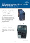
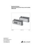
Piezo Envelope Assembly
PART NO. 396079
INSTALLATION INSTRUCTIONS
Pilot Lighting Test
APPLICATION
The 396079 Piezo Envelope Assembly is a replacement
device used with the VS8420/21 and VS8510/20/21 gas
valves, that allows manual lighting of the pilot burner. The
piezo is mounted on the gas valve and lights the pilot
burner by creating a spark when the plunger is depressed.
The connecting wire includes a terminal to connect to the
electrode of the pilot burner.
The piezo envelope assembly includes the piezo, cover
and 2-screws.
1. Turn the knob on the gas valve counterclockwise
to the PILOT position, push the knob down, and
hold in position. The pilot valve opens and allows gas
to flow to the pilot burner.
2. Push the plunger on the piezo until the pilot burner is
lit. Hold down the knob until a strong flame is present
(approximately 60 seconds).
3. Release the knob. The shaft will move upward and
engage the safety valve lever that opens the safety valve.
4. Turn the knob counterclockwise
to the ON
position. On a call-for-heat, the main valve opens and
the main burner ignites.
PIEZO
T
LO
ON
PI
OFF
HI
1. Read these Instructions carefully. Failure to follow
them could damage the product or cause a hazardous condition.
2. Check the ratings given in the Instructions and on
the product to make sure the product is suitable for
your application.
3. Installer must be a trained, experienced service
technician.
4. After installation is complete, check out product
operation as provided in these Instructions.
M12899
SCREWS (2)
TOP VIEW
OF KNOB
COVER
ON
PIEZO
OT
OFF
Mounting and Wiring the Piezo
PIL
When Installing this Product...
LO
INSTALLATION
GAS CONTROL KNOB
IMPORTANT
This installation requires working within the
combustion chamber, follow instructions carefully.
1. Turn the knob on the gas valve to the OFF position.
See Fig. 1.
2. Disconnect pilot burner wire from piezo wire.
3. Remove the two screws from the cover.
4. Remove and discard the existing; cover, piezo and
screws.
5. Replace the existing piezo with the new piezo.
6. Place the new cover over the new piezo.
7. Screw the new screws into the new cover.
8. Connect the pilot burner wire to the piezo wire.
Home and Building Control
Honeywell Inc.
Honeywell Plaza
P.O. Box 524
Minneapolis, MN 55408-0524
M12896
Fig. 1. Exploded view of the piezo assembly and pilot
burner connection with VS8520 gas valve.
Home and Building Control
Honeywell Limited-Honeywell Limitée
155 Gordon Baker Road
North York, Ontario
M2H 3N7
Copyright © 1998 Honeywell Inc. • All Rights Reserved
69-1206–1 L.C. Rev. 9-98
Printed in U.S.A. on recycled
paper containing at least 10%
X-XX UL
post-consumer
paper fibers.
69-1206-1
www.honeywell.com