1
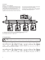
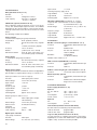
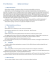
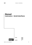
Operating Instructions
Universal measuring unit for heavy current variables
SINEAX CAM
CAM Be
Camille Bauer Ltd.
Aargauerstrasse 7
CH-5610 Wohlen/Switzerland
Phone +41 56 618 21 11
Fax +41 56 618 35 35
[email protected]
www.camillebauer.com
156 481-12
09.10
Operating Instructions
Universal measuring unit for heavy current variables SINEAX CAM
Obligatory safety instructions are marked with the following
symbols in these directions:
2. Scope of supply
SINEAX CAM (1)
1 Safety instructions (2)
1 Software and documentation CD (3)
1 USB cable (4)
1
2
Device may only be disposed of in a professional manner!
Contents
1. Read first and then... ....................................................2
2. Scope of supply ...........................................................2
3. Brief description ...........................................................2
4. Physical installation ......................................................2
4.1 Mounting ................................................................2
4.2 Releasing ................................................................3
5. Electrical connections ..................................................3
5.1 Inputs and outputs .................................................3
5.2 Interface .................................................................5
6. Commissioning.............................................................6
6.1 Software installation ...............................................7
6.2 Parametrization ......................................................7
6.3 Simulation / measurement acquisition ...................7
6.4 Protecting devices ..................................................7
6.5 MODBUS ................................................................7
6.6 Graphic display (optional).......................................7
6.7 Modbus/TCP ..........................................................8
6.8 IEC 61850 ...............................................................8
7. Technical data ..............................................................8
7.1 Measurement input ................................................8
7.2 I/O-Interface .........................................................10
7.3 Interface ...............................................................10
7.4 Further information ...............................................10
7.5 Logger and lists (optional) ....................................11
8. Maintenance ...............................................................12
9. Dimensional drawings ................................................12
10. Safety notes ...............................................................12
11. Declaration of conformity ...........................................12
1. Read first and then …
Perfect and safe operation requires that Operating Instructions has been read and understood!
This device should only be handled by staff
members who are familiar with it and authorised
to work on electric facilities.
The device must be closed down if safe operation is not
possible any more (e.g. visible damage). All connections
are to be switched off. The device must be returned to our
plant or to a service centre authorised by us.
An intervention in the device cancels any warranty
claim!
2
4
3
3. Brief description
SINEAX CAM is designed for measurements in electric
distribution systems or in industrial facilities. Along with the
current system state the pollution due to non-linear loads as
well as the overall load of the supply system can be detected.
Consistent measurement also guarantees that every network
change is reliably acquired and included in measured date.
The high-performance measuring system makes the device
also suitable for strong distorted systems as well as for zero
crossing or phase-angle controls.
The I/O interface may be individually assorted depending on
the application. Up to 4 modules with different functionality
may be used.
The logger allows long-term recordings of measurement
progressions, e.g. to monitor the variable load of transformers, as well as meter readings at definable times. Lists
offer the chronological recording of events, alarms or system
messages for further analysis of occurrences in the power
system.
The graphic display is intended for on-site visualization of
measurements, lists and alarms. Via keypad the user can
e.g. acknowledge alarms or reset extreme values.
4. Physical installation
4.1 Mounting
The device is mounted on a top-hat rail.
Please ensure tha the operating temperature limits
are not exceeded when determining the place
of mounting (place of measurement):
– 10 … 55 °C
Snap housing on the top-hat rail (EN 50 022) (see Fig. 1).
Digital outputs 12/24 V DC
+
x = 4..7
x1 x2 x3 x4
i = 1..4
C1 C2 C3 +
I/O i:
Digital I/O
Rel.
–
24 V
IN
Fig. 1. Mounting on top-hat rail 35 x 15 or 35 x 7.5 mm.
22 kΩ
Counter
1)
COM
1) Recommended if input resistance > 100 kΩ
4.2 Releasing
HV-Input 110/230 VAC
Digital inputs 12/24 V DC
24 VDC
+
–
Remove the housing from the mounting rail according to
Figure 2.
110-230 VAC
~
x = 4..7
x1 x2 x3 x4
C3 +out
-inp
Digital I/O
C1 C2
I/O i:
i = 1..4
Fig. 2
71 72 73 74
~
I/O 4:
~
110/230 V
Digital inputs 125 V DC
5. Electrical connections
125 VDC
+
–
Screw connections are used. They are designed for cross
sections of 4 mm2 for single wire leads and 2 x 2.5 mm2 for
multiwire leads.
Ensure under all circumstances that the leads are
free of potential when connecting them!
71 72 73 74
Please observe, …
… that the data on the type plate must be adhered to!
I/O 4:
Modbus
+A –B
GND
+out
-inp
Digital I/O
C3
Subbus
V+ +A –B
GND
USB
2
1
3
1
2
3
I/O 1
I/O 2
I/O 3
I/O 4
4
41 42 43 44
51 52 53 54
61 62 63 64
71 72 73 74
Re
USB
Link
A marked and easily accessible switch for turning off the
power supply has to be arranged in the vicinity of the
device.
In case of a supply of direct current > 125 V DC, an
external fuse has to be provided in the power supply
circuit.
Otherwise, the national provisions (e.g. in Germany VDE
0100 “Conditions concerning the erection of heavy current facilities with rated voltages below 1000 V”) have to
be observed in the installation and material selection of
electric lines!
C1 C2
5.1 Inputs and outputs
Analog outputs
Analog inputs
+
Rext
x = 4..7
Rext
x1 x2 x3 x4
I - + I -
21 22 23
31 32 33
1
3
4
6
7
9
10
12
2
5
8
11
Rel 1
Rel 2
k
l
k
l
k
l
k
l
U1
U2
U3
N
I1
x = 4..7
C1+ C1- C2+ C2I/O i:
0-20 mA
i = 1..4
I3
IN
Power supply
x1 x2 x3 x4
Rel 1
i = 1..4
I2
13 14
C1+ C1- C2+ C2I/O i:
0-20 mA
21
22
Rel 2
23
31
32
33
When the device is switched
off, the status of the relay
contact is not defined.
Dangerous voltages may
occur.
3
Connection modes
All voltage measurement inputs must originate
at circuit breakers or fuses rated 10 Amps
or less. This does not apply to the neutral
connector. You have to provide a method for
manually removing power from the device,
such as a clearly labeled circuit breaker or a
fused disconnect switch.
When using voltage transformers you have
to ensure that their secondary connections
never will be short-circuited.
No fuse may be connected upstream of the
current measurement inputs!
When using current transformers their secondary connectors must be short-circuited
during installation and before removing the
device. Never open the secondary circuit
under load.
Network /
application
Terminal arrangement
2 11 1
2 11 1
3
k
Four-wire
three-phase
system
balanced
load
I: L1
L1
N
L1
N
2 11 1
u
L
v
U
L1
L2
L3
N
K
l
3
V
k
l
K
L
Current
transf.
L2
L3
Terminals
2
11
1
1
L2
L3
N
N
3
3
2
5
8
1
3
4
6
7
9
2
5
8
1
3
4
6
7
9
L1
L2
L3
K
l
L
k
2 11 1
u
k
V
l
K
2
Three-wire
three-phase
system
asymmetrical load
3
v
U
L1
N
L
2
3
8 1
5
5
3
8 1
k
L1
L2
L3
L1
L2
L3
2
8
5
u
v
u
v
U
V
U
V
k
L1
L2
L3
K
l
K
Current
transf.
L2
L3
l
L
Terminals
2
5
8
1
1
L2
L3
L3
L1
L1
L2
3
3
K
l
l
L
k
K
l
L
K
2
1
8
5
u
u
4
3
6
L
7
9
u
x
x
x
X
X
X
U
U
U
k
K
l
k
l
L
k
K
l
L
K
L
3 single-pole isolated voltage transformers
in the high-voltage system
L
3
1
L1
L2
L3
L1
L2
L3
Connect voltage according to the following
table in case of current measurement via
L2 or L3:
4
L1
L2
L3
N
Connect voltage according to the following
table in case of current measurement via
L2 or L3:
3
k
Three-wire
three-phase
system
balanced
load
I: L1
3
Terminal assignment
2 11 1
Singlephase
AC mains
2 11 1
L1
L2
L3
N
The connection of the inputs depends on the configured
system (connection type). The required device external
fusing of the voltage inputs is not shown in the following
connection diagrams.
Network/
application
3
Network /
application
2
Three-wire
three-phase
system
asymmetrical load
Aron
measuring
circuit
Network /
application
Terminal arrangement
8
5
3
1
9
7
2
8
5
3
1
k
L1
L2
L3
L1
L2
L3
2
L1
L2
L3
8
5
1
u
v
u
v
U
V
U
V
k
K
3
k
L1
L2
L3
l
L
8 11 1
5
2
l
L
4
3
6
9
7
8
5
1
u
u
u
x
x
x
X
X
X
U
U
U
k
K
k
8
11 1
3
4
6
7
9 10 12
3
2
8 11 1
3
4
6
7
9 10 12
L1
L2
L3
N
l
L
7
9
Four-wire
three-phase
system
asymmetrical load
Open Y
circuit
l
k
L
l
K
L
9 10 12
7
2
l
L
K
9
7
K
2
K
Terminal arrangement
k
L1
L2
L3
N
k
l
L
k
K
l
L
K
xx
3
2
k
XX
8 11 1
5
L1
L2
L3
N
4
3
k
K
l
6
7
k
9 10 12
4
5
7
6
L
8
9 10 11 12
k
l
8 11 1
5
u
u
x
x
X
X
X
U
U
U
4
3
k
k
K
l
k
6
7
k
K
k
l
l
K
L
L
K
L
K
L
K
L
l
L
5
1
3
4
6
2
5
1
3
4
6 10 12
11
k
l
L
K
L1
L2
N
Split phase
(”Two-phase
network”)
asymmetrical load
l
L
K
2
9 10 12
l
L
k
l
L
K
x
k
l
UU
2 single-pole isolated voltage transformers
in the high-voltage system
L
K
u
L1
L2
L3
N
l
L
K
2
L1
L2
L3
N
l
uu
2
Four-wire
three-phase
system
asymmetrical load
k
L
K
1
L1
L2
L3
N
l
K
L
k
3 single-pole isolated voltage transformers
in the high-voltage system
U1
U2
U3
N
I1
I2
2
5
8
11
1
3
L1
L2
N
I3 COM
4
6
+ 3V -
IN COM
7
10
9
K
l
k
l
L
k
K
11
l
L
K
L
12
L1
L2
L3
N
Example with ACP FLEX 300x_5 current sensors 30/300/3000A, which need a 3V power supply
5
5.2 Interface
RS485 bus connection (Modbus)
The terminals (1, 2, 3) are galvanically isolated from the CAM.
The signal wires (1, 2) must be twisted. The GND (3) can be
connected with a wire or the cable screen. Screened cables
must be used in an environment with interference.
The supply resistors (Rs) must be in the bus master interface.
simple RS converters do not have these resistors. Devices that
have resistors are e.g. W&T13601 (PC print), and W&T86201
converter from Wiesemann & Theis GmbH).
Avoid drop cables. A straight network is ideal. A maximum
of 32 devices can be connected. The bus configuration is
made using the CB-Manager software.
MASTER
1)
+ 3.3/+5V
Rx/Tx+,A
Rs
Rx/Tx-,B
GND
Rs
RS485 Bus
Rt
Rt
+A -B
1 2
-GND
+A -B
1 2
3
CAM
-GND
3
+A -B
-GND
+A -B
-GND
1
3
1
3
2
2
CAM
CAM
CAM
1
2
31
3
1) One ground connection only. This is possibly already made at the master (PC).
Rt Termination resistors: 120 Ω each for long cables (> approx. 10 m)
Rs Bus supply resistors: 500 … 1000 Ω each
6. Commissioning
Prior to starting, check that the connection data of the transducer agrees with the system data (see type
label).
The power supply to the transducer can then be switched on and the signals applied to the measuring inputs.
2
3A
1
4
5
6
4
5
6
Type label of device with conventional current inputs
2
3B
1
Type label of device with Rogowski current inputs (example with 3V supply for Rogowski coil integrator)
6
Symbol
Meaning
Pos.
Meaning
Device may only be disposed of in a professional
manner!
1
Works No., Manufacturing date
Double insulation, device of protection class 2
2
Terminal connections relay outputs
CE conformity mark. The device fulfills the requirements of the applicable EC directives.
3A
Terminal connections current inputs
Caution! General hazard point. Read the operating
instructions.
3B
Terminal connections when using Rogowski coils
General symbol: Input
4
Terminal connections voltage inputs
General symbol: Output
5
Input frequency range
General symbol: Power supply
6
Terminal connections power supply
6.1 Software installation
For the parametrization of the device the supplied PC software
CB-Manager has to be installed. To do so, execute the file
setup.exe in the CB-Manager directory on the CD.
The file “Read Me First.pdf” on the software CD
contains all information about the installation of
the CB-Manager software as well as assistance
for problems concerning USB support.
6.2 Parametrization
The usage of the softwarer is comprehensively described
under Help | Contents. There you will find also all detail information, which may also be requested context specific. Hereinafter an overview about existing help topics is shown.
known from the control panel of Windows. In each register
you may request context specific help. Therefore this manual
will only describe some functions using elements from more
than one register.
Sequence
When entering the device configuration you have to consider
a useful sequence. After defining the device hardware in the
register device you have to enter the input parameters, because all the following inputs will depend on these settings.
A help to do this is the function “Next”, which navigates you
through the registers in a predefined sequence, depending
on the selected hardware. This function minimizes possible
dependencies.
State signalling to digital or relay outputs
Only via logic module it is possible to output a determined
logic state to a digital or relay output. Logic states may be
determined from limit value states, states of digital inputs,
values received via bus interface or previous calculated logic
states. But all these possible logic inputs have to be defined
in advance: Limit values in the register limit value and digital
inputs in the register I/Ox, which must have the functionality
digital input. Further information may be obtained from the
help of the logic module.
Meters
The device configuration may be performed ONLINE (with
existing connection to the device) or OFFLINE (without connection to the device). Select Parameter | Edit in the device
menu to see an overview of the present settings. You always
will be asked if the present parametrization should be read
from the device.
The complete configuration of the device is devided in subjects
and displayed in a register form. This type of display is well
Analog or digital inputs may be used to build meters. The
definition of the measurands to summarize is done via the
I/O registers of the appropriate I/O modules. The register
meters will then display all possible meters and provides the
possibility to activate the tariff switching to build high and low
tariff meters. This meters list does not contain the 12 active
and reactive power meters of the standard fitting.
6.3 Simulation / Measurement acquisition
The behaviour of the I/O modules may be simulated during
commissioning. By setting states or measurement values it
is possible to test if following circuits show the correct behaviour resp. if the SINEAX CAM responds to input devices
the right way.
7
All measurement values may be read via USB or RS485 interface and displayed using the CB-Manager software. Use
the device menu “visualisation” and the desired measurement
type to go to the appropriate measurement representation and
start the acquisition. The data will be displayed and logged.
The logged data may be stored on disk for future analysis.
7. Technical data
The complete technical data is given in the data sheet of
the device.
7.1 Measurement input (Terminals 1-12)
Frequency range:
45…50/60…65 Hz or
10…50/60…70 Hz or
10…50/60…140 Hz
Measurement TRMS:
up to the 63rd harmonic
6.4 Protecting devices
For each device user rights can be configured. The right to
change configuration data or to set/reset extreme values,
meters or slave pointers may be committed this way selectively for up to 3 different users. To perform appropriate
functions it is then necessary to enter usename and password
in advance.
Measurement category: ≤ 300 V CATIII, ≤ 600 V CATII
Current measurement
Rated current:
1 A (+ 20%), 1 A (+ 100%),
5 A (+ 20%), 5 A (+ 100%)
To be able to define user rights the input of an administrator
login is required. The factory setting is:
Overriding max.:
10 A (sinusoidal)
Consumption:
≤ I2 x 0.01Ω per phase
User:
admin
Password: admin
Thermal ratings:
12 A continuous
100 A, 10 x 1 s, Interval 100 s
ATTENTION: To reset forgotten passwords it’s necessary to
send the device back to the factory!
Instead of current inputs the version for Rogowski coils
provides voltage inputs of nominal 5 V (max. 10 V).
6.5 MODBUS
For customer specific MODBUS solutions the protocol and
all necessary information is summarized in the document
“SINEAX CAM Modbus interface”. This may be found on
the CD as well.
Voltage measurement
Rated voltage:
600 VLN, 1040 VLL (sinusoidal)
Consumption:
≤ U2 / 3 MΩ per phase
Input impedance:
3 MΩ per phase
Thermal ratings:
480 VLN, 832 VLL continuous
600 VLN, 1040 VLL, 10 x 10 s,
Interval 10 s
800 VLN, 1386 VLL, 10 x 1 s,
Interval 10 s
6.6 Graphic display (optional)
The parametrization of the graphic display and the assembling
of user specific measurement displays is performed using
the CB-Manager software. Parameters like contrast or the
selection of the display language (English, German, French,
Czech, Spanish, Dutch, Italian) can be set also directly using
the keypad.
The operation of the graphic display is described in a separate
document, which is attached in English and German to all
devices equipped with display. The appropriate manuals for
all languages may be found on the provided software CD.
6.7 Rogowski current inputs (optional)
This version provides instead of current inputs voltage inputs
for connecting the integrator circuit of Rogowski coils. These
can be fitted quickly and easily without opening the current
circuit and can cover a wide current range. Rogowski coils
can respond to fast-changing currents and transmit harmonics much better than conventional current transformers.
Thus this version is suited for applications where an accurate
analysis of harmonics resp. system feedback is required, as
well as for test facilities, where the device under test must
be replaced often and quickly. The power supply of the
Rogowski coil integrator can be performed via CAM directly.
6.8 Modbus/TCP
The Ethernet communication by means of the Modbus/TCP
protocol is described in the separated document “Modbus/
TCP interface SINEAX CAM” (see documentation CD).
6.9 IEC 61850
The IEC 61850 communication is documented separately. See documentation on the CD or on our homepage
http://www.camillebauer.com
8
57.7 … 400 VLN, 100 … 693 VLL
Overriding max.:
System
Single-phase
Split Phase
3-wire system, balanced load
3-wire system, unbalanced load
3-wire system, unbalanced load (Aron)
4-wire system, balanced load
4-wire system, unbalanced load
4-wire system, unbalanced load (Open-Y)
1L
2L
3Lb
3Lu
3Lu.A
4Lb
4Lu
4Lu.O
Basic accuracy under reference conditions
acc. IEC/EN 60 688, sinusoidal 50-60 Hz, 15 to 30 °C
Voltage:
Current:
Power:
Power factor:
Frequency:
Voltage unbalance:
Harmonics:
THD Voltage:
TDD Current:
Energy:
Active energy direct connection:
Active energy transformer connection:
Reactive energy:
± 0.1% FS a)
± 0.1% FS a)
± 0.2% FS b)
± 0.1°
± 0.01 Hz
± 0.2%
± 0.5%
± 0.5%
± 0.5%
± 0.2% FS b)
Kl. 1 / EN 62 053-21
Kl. 2 / EN 62 053-21
Kl. 2 / EN 62 053-23
Influence quantities and permissible variations
Basic measurement quantities
a)
: FS: Maximum value of the input configuration
(Full Scale)
b)
: FS: FS-Voltage x FS-Current
Measured quantity
present
max
1L
2L
3Lb
3Lu
3Lu.A
4Lb
4Lu
4Lu.O
System analysis quantities
Measured quantity
Voltage unbalance
unb. U
THD Voltage
THD.U1N
THD Voltage
THD.U2N
THD Voltage
THD.U3N
THD Voltage
THD.U12
THD Voltage
THD.U23
THD Voltage
THD.U31
TDD Current
TDD.I1
TDD Current
TDD.I2
TDD Current
TDD.I3
Harmonics
H2-50.U1
Harmonics
H2-50.U2
Harmonics
H2-50.U3
Harmonics
H2-50.U12
Harmonics
H2-50.U23
Harmonics
H2-50.U31
Harmonics
H2-50.I1
Harmonics
H2-50.I2
Harmonics
H2-50.I3
•
•
•
•
•
•
•
•
•
•
•
•
•
•
•
•
•
•
•
•
•
•
•
•
•
•
•
•
•
•
•
•
•
•
•
•
•
•
✓
✓ ✓
✓
✓
✓ ✓
✓
✓
✓
✓
✓ ✓ ✓
✓
✓
✓
✓
✓
✓
✓
✓ ✓
✓
✓
✓
✓
✓ ✓ ✓
✓
✓
✓
✓
✓
✓
✓
✓
✓
✓
✓
✓
✓
✓
✓ ✓ ✓ ✓
✓
✓ ✓
✓
✓ ✓
✓ ✓ ✓
✓ ✓
✓ ✓
✓
✓
✓
✓ ✓ ✓ ✓
✓
✓ ✓
✓
✓ ✓
THD U (Total Harmonic Distortion): Harmonic content related
to the fundamental of the RMS value of voltage.
TDD I (Total Demand Distortion): Harmonic content related
to the fundamental of the RMS value of the rated current.
Energy meters (High and low tariff)
Active energy:
Incoming
Active energy:
Outgoing
Reactive energy:
Incoming
Reactive energy:
Outgoing
Reactive energy:
inductive
Reactive energy:
capacitive
Relationship between PF, QF and LF
Output
ind.
ind.
cap.
cap.
QF
PF
–180
–90
0
90
180
LF
ϕ
Voltage
U
Voltage
U1N
Voltage
U2N
Voltage
U3N
Voltage
U12
Voltage
U23
Voltage
U31
Voltage
UNE
Current
I
Current
I1
Current
I2
Current
I3
I-Bimetal 1-60 min
IB
I1-Bimetal 1-60 min IB1
I2-Bimetal 1-60 min IB2
I3-Bimetal 1-60 min IB3
Neutral current
IN
Active power Σ
P
Active power
P1
Active power
P2
Active power
P3
Reactive power Σ
Q
Reactive power
Q1
Reactive power
Q2
Reactive power
Q3
Apparent power Σ
S
Apparent power
S1
Apparent power
S2
Apparent power
S3
Frequency
F
Active power factor Σ PF
Active power factor PF1
Active power factor PF2
Active power factor PF3
PF Σ Incoming ind.
PF Σ Incoming cap.
PF Σ Outgoing ind.
PF Σ Outgoing cap.
React. power factor Σ QF
React. power factor QF1
React. power factor QF2
React. power factor QF3
LF power factor Σ
LF
LF power factor
LF1
LF power factor
LF2
LF power factor
LF3
(U1N+U2N) / 2
Um
(U1N+U2N+U3N) / 3 Um
(U12+U23+U31) / 3 Um
(I1+I2) / 2
Im
(I1+I2+I3) / 3
Im
present
max
min
1L
2L
3Lb
3Lu
3Lu.A
4Lb
4Lu
4Lu.O
According to IEC / EN 60 688
•
•
•
•
•
•
•
•
•
•
•
•
•
•
•
•
•
•
•
•
•
•
•
•
•
•
•
•
•
•
•
•
•
•
•
•
•
•
•
•
•
•
•
•
•
•
•
•
•
•
•
•
•
•
•
•
•
•
•
•
•
•
•
•
•
•
•
•
•
•
•
•
•
•
•
•
•
•
•
•
•
•
•
•
✓ ✓
✓
✓
✓
✓
✓
✓
✓
✓
✓
✓
✓ ✓ ✓
✓ ✓ ✓
✓ ✓ ✓
✓
✓
✓
✓
✓
✓
✓ ✓
✓ ✓
✓ ✓
✓
✓
✓
✓ ✓
✓ ✓
✓ ✓
✓
✓ ✓
✓ ✓
✓ ✓
✓
✓ ✓ ✓ ✓ ✓ ✓
✓
✓
✓ ✓ ✓ ✓ ✓ ✓
✓
✓
✓ ✓ ✓ ✓ ✓ ✓
✓
✓
•
✓ ✓ ✓ ✓ ✓ ✓
✓ ✓ ✓ ✓ ✓ ✓
✓
✓
•
•
•
•
✓
✓
✓
✓
✓
✓
✓
✓
✓
✓
✓
✓
✓
✓
✓
✓
✓
✓
✓
✓
✓
✓
✓
✓
✓
✓
✓
✓
✓
✓
✓
✓
✓
✓
✓
✓
✓
✓
✓
✓ ✓ ✓ ✓ ✓ ✓
✓
✓
✓
✓
✓
✓
✓
✓
✓
✓
✓
✓
✓
✓
✓
✓
✓
✓
✓
✓
✓
✓
✓
✓
✓
✓
✓
✓
✓
✓
✓
✓
✓
✓
✓
✓
✓
✓
✓
✓
✓
✓
✓
✓
✓
✓
✓
✓
✓
✓
✓
✓
✓
✓
✓
✓
✓
✓
✓
✓
✓
✓
✓
✓
✓
✓
✓
✓
✓
✓ ✓
✓ ✓
✓
✓ ✓
✓ ✓
Measurement calculation acc. DIN 40 110 incl. 4-quadrant
measurement.
outgoing
incoming
outgoing
Fig. 3. Active power factor PF ––––, reactive power
factor QF ------, power factor LF – - – - –.
9
7.2 I/O-Interface
Input current
Relay (Terminals 21-23, 31-33)
Counting frequency (S0) ≤ 50 Hz
Number:
2
Logical ZERO
– 6 till + 20 V
Contacts:
Changeover contact
Logical ONE
30 till 157 V
Load capacity:
250 V AC, 2 A, 500 VA
30 V DC, 2 A, 60 W
Switching limit
Approx. 25 V / 0.8 mA
I/O-Module (optional, Terminals 41-74)
Up to 4 different groups of terminals (41-44, 51-54, 61-64,
71-74) with defined input/output functions are available
depending on the selected options. These groups are galvanically isolated from each other and from the rest of the
device.
The following modules are available:
< 2.5 mA
HV-Input 110/230 V AC (for terminals 71, 74 only)
1 input for RTC synchronization or state recognition
Function:
Rated voltage:
Synchronization RTC, Logic
110 till 230 V AC (≥ 100 V AC,
≤ 264 V AC)
Frequency range:
45 till 65 Hz
Logical ZERO:
0 till 40 V AC
Logical ONE:
80 till 264 V AC
Analog outputs
2 active current outputs per group of terminals
Switching limit:
Approx. 60 V AC / 1.9 mA ± 20%
Linearization:
linear, quadratic, kinked
7.3 Interface
Range:
0/4-20 mA (24 mA max.), unipolar
or
± 20 mA (24 mA max.), bipolar
Modbus connection (plug-in screw terminals 1, 2, 3)
Function:
Configuration, Measurement acquisition
Accuracy:
± 0.1% of 20 mA
Protocol:
Modbus RTU
Burden:
≤ 500 Ω (max. 10 V / 20 mA)
Physics:
Galvanical isolation:
From all other connections (connected within group of terminals)
RS-485, max. distance
1200 m (4000 ft)
Baudrate:
Configurable
(1.2 till 115.2 kBaud)
Analog inputs
2 current inputs per group of terminals
Number of bus stations: ≤ 32
Range:
0/4–20 mA (24 mA max.), unipolar
USB connection (USB Mini-B, 5 contacts)
Accuracy:
± 0.1% of 20 mA
Function:
Galvanical isolation:
From all other connections (connected within group of terminals)
Configuration, Measurement acquisition
Protocol:
USB 2.0
Digital inputs/outputs
3 per group of terminals, in relation to software configurable as
passive inputs or outputs (all the same), acc. EN 61 131-2
Subbus connection (plug-in screw terminals 1, 2, 3, 4)
Inputs (acc. EN 61 131-2 DC 24 V Type 3):
Function:
Configuration, measurement acquisition
Protocol:
Modbus/TCP or IEC 61850 (depending on the version ordered)
Function:
State input, pulse counter
Rated voltage:
12/24 V DC (30 V max.)
Input current:
< 7.0 mA
Counting
frequency (S0):
≤ 50 Hz
Logical ZERO:
– 3 till + 5 V
Logical ONE:
8 till 30 V
Switching limit:
approx. 6.5 V /2.6 mA
Function:
reserved for future device options
Ethernet (RJ-45), optional
7.4 Further information
Outputs (partly acc. EN 61 131-2):
Power supply (Terminals 13, 14)
Option 1:
AC, 50 - 400 Hz:
DC:
Consumption:
Inrush current:
100 … 230 V ± 15%
100 … 230 V ± 15%
≤ 10 W resp. ≤ 20 VA
< 25 A / 0.3 ms
Option 2:
DC:
Consumption:
24 … 60 V ± 15%
≤ 10 W
Function:
State output, pulse output,
self-monitoring
Rated voltage:
12/24 V DC (30 V max.)
Rated current:
50 mA (60 mA max.)
Switching
frequency (S0):
≤ 20 Hz
Limit module (Software function GW1 till 64)
64 Limit values for monitoring measurement limits
Load capacity:
400 Ω … 1 MΩ
Limit for ON state:
programmable
Limit for OFF state:
programmable
Digital inputs 125 V DC
3 per group of terminals
Function
State input
Rated voltage
48 / 125 V DC (157 V max.)
10
Logic module (Software function LS1 till 32)
32 Logic functions to combine logical states: Limit values,
digital inputs, LS-states and default values. Output to digital
outputs, relays or other LS functions possible.
Response time 40ms + 17ms + 0ms + 30ms = 87ms
Internal clock (RTC)
Function:
Time reference, Counter for operating hours
Accuracy:
± 2 Minutes/Month (15 till 30°C)
trimmable via PC-Software
Operating temperature: – 10 till 15 till 30 till 55 °C
Storage temperature:
– 25 till + 70 °C
Synchronization via:
Measurement input,
HV-Input 110/230 V AC,
Synchronization pulse (digital input)
Relative humidity:
< 95% no condensation
Variations due to
ambient temperature:
0.5x Basic accuracy per 10 K
> 10 years
Long term drift:
0.2x Basic accuracy per year
Altitude:
≤ 2000 m max.
Others:
Usage group II
acc. IEC / EN 60 688
Running reserve:
Response time
The total response time is the addition of the measurement
time t1 of the input quantities and the processing time t2 for
the respective output (analog output, bus, digital output,
relay).
Meas. time t1
Processing time t2
t
Ambient conditions, general information
Mechanical attributes
Dimensions:
186 x 90 x 62 mm
Mounting:
On top-hat rail acc.
DIN EN 50 022 (35 x 15 mm and
35 x 7.5 mm)
Orientation:
Any
Input quantities
Analog output
Modbus, USB
Limit
Logic
Digital
monitoring module output
Relay
Housing material:
Polycarbonat (Makrolon)
Flammability class:
V-0 acc. UL 94, self-extinguishing,
non-dripping, free of halogen
Weight:
500 g
Security
Basic measurement quantities
The current inputs are galvanically isolated from each
other.
Measurement interval:
programmable, 1 .. 999 periods
(Averaging time RMS value)
Protection class:
II (protective insulation, voltage
inputs via protective impedance)
Measurement time t1:
2 x measurement interval
+ 17ms
Pollution degree:
2
Enclosure protection:
IP 40, housing
(test wire, IEC/EN 60 529
IP 20, terminals
(test finger, IEC/EN 60 529)
Measurement time t1
System analysis quantities
Measurement interval:
18 periods
Measurement time t1:
2 x measurement interval
Analog input
Measurement time t1:
25 ms .. 30 s (programmable)
Digital input
Measurement time t1:
< 25 ms
HV-Input 110/230 V AC
Measurement time t1
Measurement category: CAT III (at ≤ 300 V versus earth)
CAT II (at > 300 V versus earth)
Rated voltage
(versus earth):
Power supply: 265 V AC
Relay:
250 V AC
I/O’s:
30 V DC
264 V AC(HV-Input)
7.5 Logger and lists (optional)
2 till 255 periods (programmable)
Total response time t1 + t2
Analog output:
t1 + 10 ms .. 60 s,
programmable
Modbus / USB:
t1
Digital output:
t1 + 8 ms + Logic module
Relay:
t1 + 30 ms + Logic module
(Logic module: Switch-in/dropout delay 0…65 s, programmable)
Example: Relay has to toggle if P > Plimit, rated frequency is
50 Hz, Averaging time is 1 period, switch-in delay
logic set to 0 s
By means of these options measurements and events may be
long-term recorded. Depending on the application 7 different
kinds of data may be acquisited:
– Progression of mean-values with interval time t1
(1s…60min)
– Progression of mean-values with interval time t2
(1s … 60min)
– Min/Max values during interval t3 (1s … 3h)
– Meter readings
– List entries of alarms
– List entries of events
– List entries of system messages
They share the available storage space of 64Mb size. The
memory allocation may be performed using the CB-Manager
11
software. Due to the high degree of freedom for the configuration of logger and lists no general information about the
maximal storage duration can be given. But these can be
seen in the software when selecting the memory allocation,
the measurands to store and the number of list entries.
The reading and analyzing of logger and list data can be
done using the CB-Analyzer software.
8. Maintenance
11. Declaration of conformity
EG - KONFORMITÄTSERKLÄRUNG
DECLARATION OF CONFORMITY
Dokument-Nr./
Document.No.:
CAM_CE-konf.DOC
Hersteller/
Manufacturer:
Camille Bauer AG
Switzerland
Anschrift /
Address:
Aargauerstrasse 7
CH-5610 Wohlen
Produktbezeichnung/
Product name:
U n i ve r s e l l e M e s s e i n h e i t f ü r S t a r k s t r o m g r ö s s e n
U n i ve r s a l M e a s u r i n g U n i t f o r h e a vy c u r r e n t va r i a b l e s
Typ / Type:
SINEAX CAM
Das bezeichnete Produkt stimmt mit den Vorschriften folgender Europäischer Richtlinien
überein, nachgewiesen durch die Einhaltung folgender Normen:
Bevore delivery the device is checked to assure your personal
safety. Unauthorized opening of the device invalidates the
warranty and the unit must be sent back to the factory for
repeating all necessary checks.
The calibration of the device and the alteration of the I/O
module disposition can be performed in our factory only. We
recommend a yearly recalibration of the device to ensure the
long-term accuracy.
The above mentioned product has been manufactured according to the regulations of the following European directives proven through compliance with the following standards:
Nr. / No.
R i c h t l i n i e / D i r e c t i ve
2004/108/EG
2004/108/EC
Elektromagnetische Verträglichkeit - EMV - Richtlinie
Electromagnetic compatibility -EMC directive
EMV /
EMC
Fachgrundnorm /
Generic Standard
Störaussendung /
Emission
Störfestigkeit /
Immunity
EN 61000-6-4 : 2007
EN 55011 : 2007+A2:2007
EN 61000-6-2 : 2005
IEC
IEC
IEC
IEC
IEC
IEC
IEC
Nr. / No.
R i c h t l i n i e / D i r e c t i ve
2006/95/EG
E l e k t r i s c h e B e t r i e b s m i t t e l z u r V e r we n d u n g i n n e r h a l b b e s t i m m t e r S p a n n u n g s grenzen – Niederspannungsrichtlinie – CE-Kennzeichnung : 95
E l e c t r i c a l e q u i p m e n t f o r u s e wi t h i n c e r t a i n v o l t a g e l i m i t s – L o w V o l t a g e D i r e c tive – Attachment of CE mark : 95
2006/95/EC
M e s s ve r f a h r e n /
Measurement methods
61000-4-2: 1995+A1:1998+A2:2001
61000-4-3: 2006+A1:2007
61000-4-4: 2004
61000-4-5: 2005
61000-4-6: 2008
61000-4-8: 1993+A1:2000
61000-4-11: 2004
EN/Norm/Standard IEC/Norm/Standard
EN 61 010-1 : 2001
IEC 1010-1 : 2001
9. Dimensional drawings
2
1
3
1
2
3
4
41 42 43 44
51 52 53 54
61 62 63 64
Ort, Datum /
Place, date:
71 72 73 74
Wohlen, 17.Februar.2009
USB
Re
98
90
Link
Unterschrift / signature:
21 22 23
31 32 33
1
3
4
6
7
9
186
10
12
2
5
8
11
13 14
63
10. Safety notes
● Before you start the device check for which power supply
it is built.
● Verify that the connection leads are in good condition and
that they are electrically dead while wiring the device.
● When it must be assumed that safe operation is no longer possible, take the device out of service (eventually
disconnect the power supply and the input voltage!).
This can be assumed on principle when the device shows
obvious signs of damage.
The device must only be used again after troubleshooting,
repair and a final test of calibration and dielectric strength
in our factory or by one of our service facilities.
● When opening the cover, live parts may be exposed.
Calibration, maintenance or repair with the device
open and live must only be performed by a qualified
person who understands the danger involved. Capacitors in the device may still be charged even though
the device has been disconnected from all voltage
sources.
12
M. Ulrich
J. Brem
Leiter Technik / Head of engineering
Qualitätsmanager / Quality manager