1
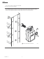
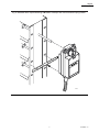
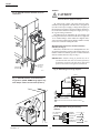
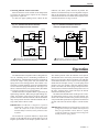
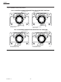
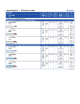
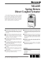
ML6185
Spring Return
Direct Coupled Actuator
The ML6185 Spring Return Direct Coupled
Rotary Actuator is a floating control motor that can
be used with controls that provide switched or
floating single pole double throw (spdt) control
output to operate dampers in heating, ventilation,
and air conditioning (HVAC) applications.
■ Mounts directly on horizontal 3/8 in., 1/2 in., and
5/8 in. round and square damper shafts by using the
appropriate insert. Most models are shipped with 1/
2 in. insert.
■ Available with or without a time-out feature. Models
without the time-out feature are designed to be used
with intelligent building management system and/or
controller.
■ Provides 50 lb-in. running and spring return torque.
■ Standard models have two 8 mm x 12 mm long set
screws for securing the damper shaft. Actuator
models are available for various shaft sizes that will
allow the damper shaft to operate centered inside the
output hub.
■ Magnetic coupling eliminates the need for mechanical stops or limit switch adjustments by limiting
stall torque to 130 lb-in. maximum.
■ 95° stroke provides necessary compression of rubber/neoprene gaskets commonly used on 90° low
leakage dampers.
■ Standard one-meter cable with color-coded leadwires allows external wire connections with 1/2 in.
conduit connectors.
■ 88 second synchronous timing can eliminate need
for feedback position indication in closed-loop temperature control applications.
■ Can mount two or more actuators on one damper
shaft to increase output torque for use on dampers
larger than 16 square feet.
■ Removable splined output hub permits premounting
of the hub on the damper shaft, providing installation
flexibility.
■ Reversible mounting allows actuator to be used for
either clockwise (cw) or counterclockwise (ccw)
spring rotation.
CONTENTS
Specifications ................................................. 2
Ordering Information ..................................... 2
Installation ..................................................... 4
Operation ....................................................... 9
Checkout ....................................................... 11
■ Designed for both single-point and three-point mounting, providing installation flexibility.
G.R. • Rev. 4-95 • ©Honeywell Inc. 1995
1
63-2483—2
63-2483-2
ML6185
SPECIFICATIONS • ORDERING INFORMATION
Specifications
Stall Driving Maximum: 130 lb-in. (15 N•m).
ACTUATOR STROKE: 95° Nominal ± 2°, mechanically
limited.
ACTUATOR TIMING at 90° Stroke:
88 +/- 2 seconds synchronous at 60 Hz from 0°F to
140°F;
106 +/- 2 seconds at 50 Hz;
100 seconds at -30°F.
Spring Wind Timing (Upon Power Restoration Only):
100 seconds nominal at 60 Hz, 120 seconds at 50 Hz.
Spring Return Timing:
10 seconds minimum per 90° at 72°F no load;
30 seconds maximum per 90° at 72°F at rated load;
5 minutes maximum at -30°F at rated load.
AMBIENT TEMPERATURE RANGE: -30°F to +140°F
(-35°C to +60°C).
STORAGE TEMPERATURE: -30°F to 150°F (-35°C to
65°C).
HUMIDITY: 5 to 95 percent relative humidity, noncondensing.
MOUNTING: Mounts directly on horizontal 3/8 in. to
5/8 in. (12 to 16 mm) round or square damper shaft.
Minimum shaft length required: 3.5 in. (76 mm) when the
shaft attachment is made on the side of the actuator
opposite the duct; 0.65 in. (16 mm) when the hub is
mounted on the shaft before the actuator is installed. Most
actuators are shipped with specifically sized hubs. Some
models contain an assembly with assorted hub inserts.
Mounting bracket is included with most models.
DIMENSIONS: See Fig. 1.
MODELS: ML6185 Spring Return Direct Coupled Rotary
Actuators.
ML6185A: Medium Torque (50 lb-in.) Direct Coupled
Rotary Actuator without auxiliary switches and
without time-out function.
ML6185C: Medium Torque (50 lb-in.) Direct Coupled
Rotary Actuator with two line voltage rated auxiliary switches, without time-out function.
ML6185D: Medium Torque (50 lb-in.) Direct Coupled
Rotary Actuator without auxiliary switches and
with time-out function.
ML6185F: Medium Torque (50 lb-in.) Direct Coupled
Rotary Actuator with two line voltage auxiliary
switches and time-out function.
ELECTRICAL RATINGS:
Power Input: 24 Vac ± 20%, 50/60 Hz.
Power Consumption:
ML6185A-C: 12 VA maximum at 24 Vac.
ML6185D,F: 12 VA maximum at 24 Vac.
Auxiliary Switch Ratings: 120, 240 Vac: 3 AFL, 18 ALR,
1A pilot duty.
Control: Standard models include nonplenum UL/
CSA rated, 30V, 60°C, 20 gauge cable.
Auxiliary Switch: UL/CSA rated 300V 90°C, 18
gauge.
TORQUE RATINGS (at Rated Voltages):
Lift and Hold: 50 lb-in. (6 N•m).
Breakaway Minimum: 50 lb-in. (6 N•m).
Stall Minimum: 50 lb-in. (6 N•m) spring return.
Ordering Information
When purchasing replacement and modernization products from your TRADELINE® wholesaler or distributor, refer to the TRADELINE®
Catalog or price sheets for complete ordering number, or specify:
1. Model number.
2. Application.
If you have additional questions, need further information, or would like to comment on our products or services, please write or phone:
1. Your local Honeywell Home and Building Control Sales Office (check white pages of your phone directory).
2. Home and Building Control Customer Logistics
Honeywell Inc., 1885 Douglas Drive North,
Minneapolis, Minnesota 55422-4386 (612) 951-1000
In Canada—Honeywell Limited/Limitée, 740 Ellesmere Road, Scarborough, Ontario M1P 2V9. International Sales and Service
offices in all principal cities of the world.
63-2483—2
2
ML6185
SPECIFICATIONS
Fig. 1—Approximate dimensions of ML6185 Spring Return Direct Coupled Actuator and mounting
bracket in in. (mm).
1-5/32 (29)
6-25/32 (173)
1-17/32 (39)
3-1/16
(79)
8-9/32 (210)
3-29/32
(99)
23/32
(18)
3-15/16 (100)
1-21/32
(42)
3-1/2
(89)
1-5/8
(41)
1-9/32
(32)
CLEARANCE
REQUIRED
FOR SPLINED
HUB MOUNTING
3-29/32
(99)
o
135
± 15o
1/2 (13)
1-13/32
(36)
1-3/32
(28)
13/32
(10)
13/64 (5)
3/4 (19)
5/16
(8)
3/8
(10)
1-13/32 (36)
4-13/32 (112)
1-5/8 (41)
10-13/32 (264)
MOUNTING BRACKET
3
M8257
63-2483—2
ML6185
SPECIFICATIONS • INSTALLATION
DEVICE WEIGHT: 4.0 lb (1.82 kg).
NOISE RATING: (Driving only) 45 dBA maximum at
0.9m.
SPRING ROTATION: Clockwise (cw); counterclockwise
(ccw) by reverse mounting.
POSITION INDICATOR: Mounted on actuator hub.
ACTUATOR DESIGN LIFE:
Full Stroke Cycles: 60,000.
Repositions: 1,500,000.
Spring Return Cycles: 7,500.
APPROVALS:
UL94-5V: (Enclosure) Plenum rating.
UL873: (Line voltage auxiliary switches).
CSA: FILE NUMBER E4436, Guide Number XAPX.
ENVIRONMENTAL PROTECTION RATINGS: NEMA1
standard with damper shaft in horizontal position.
MOUNTING TAB: For use with Universal mounting bracket.
ACCESSORIES:
205820A 3-Point Mounting Kit.
205830A Crank-Arm Accessory.
205753 Hub Sleeve, 3/8 in.
205758 Hub Sleeve, 5/8 in.
Installation
WHEN INSTALLING THIS PRODUCT…
1. Read these instructions carefully. Failure to follow
them could damage the product or cause a hazardous
condition.
2. Check the ratings and description given in this specification to make sure the product is suitable for your application.
3. Installer must be a trained, experienced service
technician.
4. After installation is complete, check out product operation as provided in these instructions.
A mounting bracket (see Fig. 1) is provided with some
models to aid in installing the actuator. The bracket can be
bent to any shape to support the actuator at the correct
height.
The ML6185 Direct Coupled Actuator can also be threepoint mounted using the two front gear housing slots and
the adapter bracket. Secure two screws through the two
front gear housing slots and position the adapter bracket to
secure the rear of the actuator. Three point mounting is used
for foot mounting the actuator or internally mounting the
actuator in the duct, when direct shaft coupling is not
possible.
CAUTION
CAUTION
1. Disconnect power before installation to prevent
electrical shock or equipment damage.
2. Never turn motor output hub by hand or with a
wrench.
3. Do not install actuator in areas with acid fumes
or other deteriorating vapors that might attack
the metal parts of the actuator.
4. Do not install actuator in areas with escaping
gas or other explosive vapors that could be
ignited by a spark from the actuator or attached
accessories.
Do not use the actuator as a shaft bearing. The
actuator must be used only to supply rotational
torque. To prevent damage to the actuator, avoid
any side loads to the actuator output coupling
bearings.
PREPARATION
Before installing the ML6185 on the damper shaft,
determine the opening direction of the damper shaft to
determine the correct spring return rotation and correctly
connect the wiring. The ML6185 can be mounted to provide clockwise or counterclockwise spring return. Reverse
the actuator, if necessary, to provide the desired spring
action.
LOCATION
Install the actuator in any location free from acid fumes or
other deteriorating vapors that might attack the metal parts of
the actuator. Make sure the location is not subject to escaping
gas or other explosive vapors that could accidentally be
ignited by a spark from the actuator or its attached parts.
Install the actuator in a location that allows enough clearance for mounting accessories and for servicing.
INSTALLATION
Installing the Actuator and Mounting Bracket (Single
Point Mounting)
When the direction of the damper shaft rotation is determined (either cw
or ccw
), proceed as follows:
1. Place the ML6185 Direct Coupled Actuator over the
damper shaft.
2. Position the actuator for best access to the actuator
damper shaft locking screw.
3. Install the mounting bracket (see Fig. 2) and adjust it
to support the actuator at the correct height. Mark the screw
holes for installing the mounting bracket on the damper
housing.
MOUNTING
The ML6185 Direct Coupled Actuator is designed to
operate a damper by driving the damper shaft either
cw
or ccw
depending on damper design. All
actuators are shipped in the fully closed position.
The ML6185 Direct Coupled Actuator is designed for
single-point mounting when using an adapter bracket. Singlepoint mounting is typically used when the actuator is mounted
on the damper frame.
63-2483—2
4
ML6185
INSTALLATION
4. Remove the mounting bracket and actuator.
5. Drill or center punch the starting holes for the mounting bracket screws (or use no. 10 self-tapping sheet metal
screws).
6. Place the actuator and mounting bracket back into
position over the damper shaft and install the mounting
bracket screws.
7. Tighten the two 8 mm x 12 mm long set screws firmly
against the damper shaft (maximum tightening torque is
100 lb-in.).
Fig. 2—Installing mounting bracket on ML6185
Direct Coupled Actuator.
30
60
90
Installing the Actuator for Three-Point Mounting
The ML6185 Direct Coupled Actuator is designed with
removable hub sleeves to accommodate specific damper
shaft sizes. Proper sleeve selection is necessary when threepoint mounting is used to avoid excessive strain on the
output gear. Most ML6185 Actuators are shipped with a
1/2 in. hub sleeve. For field use, several hub sleeve sizes are
available. See the Accessories listing in the Specifications
section. Shaft sizes are stamped on the sleeves.
The ML6185 Direct Coupled Actuator can be mounted
directly on the motor shaft with the actuator in any position
when the actuator housing is parallel with the damper
housing or frame. (See Fig. 7.)
The ML6185 Direct Coupled Actuator has a reversible
output hub. The hub is factory mounted on the top of the
actuator gear housing. When attaching to damper shafts
less than 3.5 in. (76 mm) long, or for ease of mounting, the
output hub can be mounted to the inside of the actuator gear
housing. See Fig. 3. Be careful when removing the retaining ring that secures the output hub to the actuator housing.
Use a flatheaded screwdriver to pry the ring loose.
M9386
Fig. 3—Mounting hub to inside of actuator.
2
6
1
3
60
90
60
30
DETENT
INSERT
30
0
4
5
0
.50
INDICATOR
DETENTS
.50
0
M7228
5
63-2483—2
ML6185
INSTALLATION
Other possible mounting configurations and standard
connections are shown in Fig. 4 through 7.
Fig. 4—ML6185 Actuator mounted for counterclockwise spring rotation with the output hub inside the
actuator. (NOTE: NEMA rating applies only with damper shaft in the horizontal position.)
60
90
30
60
30
0
1
INDICATOR
DETENTS
1 COUNTER CLOCKWISE SPRING ROTATION ARROW
63-2483—2
6
M7230A
ML6185
INSTALLATION
Fig. 5—Standard direct coupled mounting of ML6185 to a damper with counterclockwise spring rotation.
60
90
30
60
30
0
.50
.50
0
M7229
7
63-2483—2
ML6185
INSTALLATION
WIRING
Fig. 6—ML6185 Actuator standard electrical
connection.
CAUTION
Disconnect power supply before wiring to prevent
electrical shock or equipment damage.
All wiring must comply with local electrical codes,
ordinances and regulations. The ML6185 is designed for
use with a Class 2 power supply. Voltage and frequency of
the transformer used must correspond with the characteristics of the motor and those of the power supply. See Fig. 8
for a typical wiring connection.
The ML6185 has an aluminum die cast housing with
two integral cast bosses on the end of the device, tapped for
1/2 in. conduit fittings. Some models are shipped with a
water seal in the conduit opening. When conduit is needed,
remove the seal before routing the cable.
60
90
30
60
30
0
.50
.50
0
ML6185 models with Factory-mounted Auxiliary
Switches (See Fig. 9)
ML6185C,F models have two nonadjustable line voltage rated spdt auxiliary switches with switches factory set
to make common to normally open at 12° and 82° rotation
from the counterclockwise stop. See Fig. 9.
IMPORTANT: Actuators driving in parallel may not be
synchronized with each other. In normal operation, if
all actuators are driven to the fully open or fully closed
position, the actuators will again be synchronized.
TO JUNCTION
BOX (UP TO
3 FT. AWAY)
MOUNTING
BRACKET
Fig. 8—ML6185 typical wiring diagram.
M7231
ML6185
OPEN
BLUE
Fig. 7—ML6185 Actuator can be mounted in
any position. (NOTE: NEMA rating applies only
with damper shaft in the horizontal position.)
MOTOR
CLOSE
YELLOW
OPTIONAL
TIME OUT
24 HOT
RED
2
POWER
SUPPLY
1
L1
(HOT)
L2
SPRING
CONTROL
24 VAC
24 GND
BLACK
1 POWER SUPPLY. PROVIDE DISCONNECT MEANS AND OVERLOAD
PROTECTION AS REQUIRED.
2 TIME OUT FUNCTION AVAILABLE WITH ML6185D,F MODELS.
M7224
Fig. 9—ML6185C,F wiring for auxiliary
switches.
60
90
30
60
30
00
5
0
50
0
AUX. SWITCHES
3A 120 VAC
WHITE/RED
12°
WHITE/BLUE
WHITE/YELLOW
BLACK/RED
82°
BLACK/BLUE
BLACK/YELLOW
M9384
63-2483—2
8
M7227A
ML6185
INSTALLATION • OPERATION
Connecting ML6185 Actuators in Parallel
ML6185 Actuators can be stacked on one damper shaft
to increase the output torque required to drive dampers
larger than 16 square feet.
To make sure proper phasing occurs, connect all four
leadwires (red, black, yellow and blue) in parallel. The
number of actuators that may be wired in parallel is dependent on the transformer VA rating. Make certain that the
connected load does not exceed the current capacity of the
controller/thermostat. See Fig. 10 and 11.
Fig. 10—Common transformer with two
controller outputs and two actuators.
Fig. 11—Common transformer with one
controller output and two actuators.
ML6185
ML6185
CONTROLLER
CONTROLLER
BLUE
BLUE
R
B
R
YELLOW
RED
L1
(HOT)
L2
RED
L1
(HOT)
L2
YELLOW
W
1
W
1
B
BLACK
BLACK
ML6185
ML6185
CONTROLLER
R
B
BLUE
BLUE
YELLOW
YELLOW
RED
RED
BLACK
BLACK
W
1 POWER SUPPLY. PROVIDE DISCONNECT MEANS
AND OVERLOAD PROTECTION AS REQUIRED.
1 POWER SUPPLY. PROVIDE DISCONNECT MEANS
AND OVERLOAD PROTECTION AS REQUIRED.
M7225A
M7226A
Operation
The ML6185 Direct Coupled Actuator is designed to be
used in ventilating and air conditioning installations to
operate dampers, ventilation flaps and louvers requiring up
to 50 lb-in. torque. If the power fails, the actuator will
spring return to the starting position. The actuator is designed for reversible mounting. Arrows are molded into the
covers to show the spring return direction. The larger cover
shows a counterclockwise (ccw) spring rotation; the smaller
cover shows a clockwise (cw) spring rotation.
The ML6185 Direct Coupled Actuator is operated by an
spdt floating controller. When using an spdt floating controller, the actuator will be driven toward its fully open
position when the controller makes R to B and toward the
fully closed position when the controller makes R to W. It
stops when neither contact is made.
four distinct positions where the indicator can be placed.
The indicator can be removed (by first removing the output
hub) to provide proper damper orientation. The indicator
can be indexed to show cw or ccw open or closed, using the
detents that are 90° apart. See Fig. 12. If the spring return
position is the open position, rotate the indicator until it
points to 90 on the scale. If the spring return position is the
closed position, rotate the indicator until it points to zero on
the scale. A detent can be felt at both stops; the detents
maintain the indicator position.
The ML6185D and ML6185F models provide a timeout function that removes power from the actuator submotor if the actuator remains in one position (closed, open
or any intermediate position) for longer than a nominal 100
seconds. This time-out function helps to extend actuator
life.
IMPORTANT: The ML6185 is designed to respond to
instantaneous contact closures from a DDC Controller. Be careful not to short cycle the actuator.
Unstable damper control may cause premature actuator failure.
IMPORTANT: The ML6185 was designed to provide 7500
spring returns; therefore, the actuator can be unpowered
daily for night shutdown control. However, rapidly
cycling the actuator by removing control voltage will
lead to premature spring failure.
The actuator has a position indicator to depict shaft
position. As the indicator moves with the shaft, it gives an
angular representation of the damper position. There are
9
63-2483—2
ML6185
OPERATION
Fig. 12—ML6185 indicator start positions.
FULLY COUNTERCLOCKWISE SPRING RETURN INDICATOR START POSITIONS
POINTER AT 90°
60
90
POINTER AT 0°
60
30
60
60
30
30
0
90
0
30
0
0
DETENT IN INSERT
DETENT IN INSERT
DRIVE CLOCKWISE TO CLOSE
(REVERSE ACTING)
DRIVE CLOCKWISE TO OPEN
(DIRECT ACTING)
FULLY CLOCKWISE SPRING RETURN INDICATOR START POSITIONS
POINTER AT 90°
60
90
30
POINTER AT 0°
60
60
90
30
30
60
30
M7235
0
0
0
DETENT IN INSERT
DRIVE COUNTERCLOCKWISE
TO CLOSE (REVERSE ACTING)
63-2483—2
DETENT IN INSERT
DRIVE COUNTERCLOCKWISE
TO OPEN (DIRECT ACTING)
10
0
M7235B
ML6185
CHECKOUT
Checkout
The ML6185 Direct Coupled Actuator can be checked
out either directly or by using a controller.
4. Connect 24 Vac to the appropriate leadwires (red to
blue or red to yellow) to move the damper to the opposite
position. The ML6185 should drive the damper.
5. If the actuator does not run, verify that the actuator is
properly installed for either cw
or ccw
rotation.
6. If the actuator operates in the opposite direction than
desired, reverse the blue and yellow leadwires.
7. If the actuator is correctly installed and still does not
run, replace the actuator.
IMPORTANT: When power is interrupted, the actuator
returns to the normal starting position using the spring
mechanism. When power is restored, the controller
input will not operate the actuator until the spring is
fully wound and locked. The spring winding process
takes approximately 100 seconds, depending on the
number of degrees of spring return remaining at power
interrupt (i.e., 10° of spring return remaining takes 10
seconds). (If the actuator is not in the closed position,
it will run to the closed position as the spring is
winding.) Once the spring is locked in its fully wound
position, the actuator responds to inputs to the red-toblue or red-to-yellow leadwires.
CONTROLLER CHECKOUT
1. Adjust the setpoint of the controller to call for cooling.
Observe the actuator.
2. If the damper is closed, it should begin to open.
3. If the damper remains closed, move the setpoint of the
controller farther below the room temperature.
4. If the damper still does not move, check for the
presence of 24 Vac in the input.
5. Make sure the actuator spring is fully wound by
applying power for at least 100 seconds.
6. If 24 Vac is present and the actuator does not operate,
reverse the controller leadwires to determine if the device
was miswired.
7. If the wiring is correct and 24 Vac is present on the input
terminals but the actuator does not run, replace the actuator.
DIRECT CHECKOUT
1. Mount the actuator for the required application (either
cw
or ccw
rotation to open the damper).
2. Check the damper position and make sure that 24 Vac is
present on the red and black leadwires.
3. Make sure the actuator spring is fully wound and
locked by applying power for at least 100 seconds.
11
63-2483—2
Home and Building Control
Honeywell Inc.
1985 Douglas Drive North
Golden Valley, MN 55422
63-2483—2
Printed
in U.S.A.
Home and Building Control
Honeywell Limited—Honeywell Limitée
740 Ellesmere Road
Scarborough, Ontario
M1P 2V9
12
Helping You Control Your World
QUALITY IS KEY