1
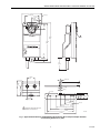
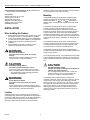
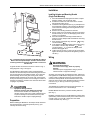
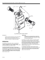
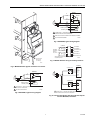
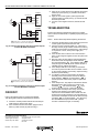
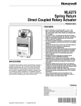
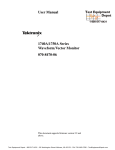
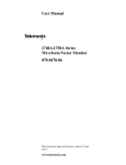
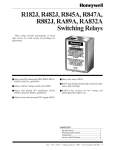
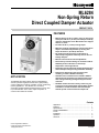
ML6284
Non-Spring Return
Direct Coupled Damper Actuator
PRODUCT DATA
FEATURES
• Mounts directly on 3/8 in. to 5/8 in. (10 to 17 mm) round
and square and 3/4 in. (19 mm) round damper shafts by
using the appropriate insert. Most models are shipped
with 1/2 in. insert.
• Provides 150 lb-in. (17 N•m) running torque.
• Magnetic coupling eliminates the need for mechanical
stops or limit switch adjustments by limiting stall
torque to 250 lb-in. (28.3 N•m) maximum.
• 95° stroke provides necessary compression of
rubber/neoprene gaskets commonly used on 90° low
leakage dampers.
• Manual clutch allows for manual adjustment.
• 92-second synchronous timing can eliminate need for
feedback position indication in closed-loop
temperature control applications.
• Removable splined output hub permits premounting of
hub on damper shaft, providing installation flexibility.
• Designed for both single-point and three-point
mounting, to allow installation flexibility.
APPLICATION
The ML6284 Non-Spring Return Direct Coupled Damper
Actuator provides single pole double throw (spdt) floating
control of dampers in heating, ventilation, and air conditioning
(HVAC) applications. The actuator has an internal,
electrically isolated feedback potentiometer that can be used
to provide indication of the motor output hub position or
control a slave Series 90 actuator.
• Available with or without a time-out feature. Models
without the time-out feature are designed to be used
with intelligent building management system and/or
controller.
• Standard models have two 8 mm by 12 mm long set
screws for securing the damper shaft. Actuator models
available for various shaft sizes that allow damper
shaft to operate centered inside the output hub.
Contents
Application ........................................................................
Features ...........................................................................
Specifications ...................................................................
POUR COMMANDER ......................................................
French
Installation ........................................................................
Operation ..........................................................................
Checkout ..........................................................................
® U.S. Registered Trademark
© 2004 Honeywell International Inc.
All Rights Reserved
1
1
2
2
4
6
8
63-2505
ML6284 NON-SPRING RETURN DIRECT COUPLED DAMPER ACTUATOR
SPECIFICATIONS
Models:
ML6284: Non-Spring Return Direct Coupled Damper Actuators.
ML6284A: High Torque (150 lb-in.) Direct Coupled Damper
Actuator without auxiliary switches or time-out function.
ML6284C: High Torque (150 lb-in.) Direct Coupled Damper
Actuator with two low voltage rated auxiliary switches and
without time-out function.
ML6284D: High Torque (150 lb-in.) Direct Coupled Damper
Actuator without auxiliary switches and with time-out
function.
ML6284F: High Torque (150 lb-in.) Direct Coupled Damper
Actuator with two low voltage auxiliary switches and with
time-out function.
Electrical Ratings:
Power Input: 24 Vac ± 20%, 50/60 Hz.
Power Consumption:
ML6284A-C: 5 VA maximum at 24 Vac.
ML6284D,F: 6 VA maximum at 24 Vac.
Auxiliary Switch Ratings: 24 Vac, 3 AFL, 18 ALR, 1A Pilot
Duty.
Feedback Resistor: 500 ohm linear potentiometer.
Cable Ratings:
Control: Standard models include nonplenum UL/CSA rated,
30V, 60°C, 20 gauge cable.
Auxiliary Switch: UL/CSA rated 300V 90°C, 18 gauge.
Controller Type: Floating, spdt.
Torque Ratings at Rated Voltages:
Lift and Hold Minimum: 150 lb-in. (17 N•m).
Breakaway Minimum: 150 lb-in. (17 N•m).
Stall Minimum: 150 lb-in. (17 N•m).
Stall Maximum: 250 lb-in. (28.3 N•m).
Actuator Timing at 90° Stroke:
92 ± 2 seconds synchronous at 60 Hz from -4°F to 140°F
(-20°C to +60°C).
110 ± 2 seconds synchronous at 50 Hz from -4°F to 140°F
(-20°C to +60°C).
Non synchronous below -4°F (-16°C).
Ambient Temperature Range: -30°F to +140°F (-35°C to
+60°C).
Storage Temperature: -30°F to 150°F (-35°C to 65°C).
Humidity: 5 to 95 percent relative humidity, noncondensing.
Mounting:
Mounts directly on horizontal 3/8 in. to 5/8 in. (12 to 17 mm)
round or square or 3/4 in. (19 mm) round damper shaft.
Minimum shaft length required:
• 2.5 in. (64 mm) when the shaft attachment is made on the
side of the actuator opposite the duct;
• 0.65 in. (16 mm) when the hub is mounted on the shaft
before the actuator is installed.
Most actuators are shipped with specifically sized hubs. Some
models contain an assembly with assorted hub inserts.
Mounting bracket is included with most models.
Dimensions: See Fig. 1.
Device Weight: 3.0 lb (1.36 kg).
Noise Rating: Driving Only: 45 dBA maximum at 1.0m.
Position Indicator: Mounted on actuator hub.
Actuator Design Life: Full Stroke Cycles:100,000.
Repositions: 2,000,000 minimum.
Approvals:
UL94-5V Enclosure: Plenum rating.
UL873: Low voltage auxiliary switches.
UL Listed: File number E4436, Guide number XAPX.
CSA Listed: File number LR95329-17.
Torque Deratings at 24 Vac ±20%:
150 lb-in. from -20°F to +95°F (-29°C to +35°C).
133 lb-in. from 95°F to 140°F (35°C to 60°C).
150 lb-in. from -40°F to -20°F (-40°C to -29°C) (at 24 Vac
+20% only).
Actuator Stroke: 95° Nominal ± 3°, mechanically limited.
ORDERING INFORMATION
When purchasing replacement and modernization products from your TRADELINE® wholesaler or distributor, refer to the
TRADELINE® Catalog or price sheets for complete ordering number.
If you have additional questions, need further information, or would like to comment on our products or services, please write or
phone:
1. Your local Honeywell Automation and Control Products Sales Office (check white pages of your phone directory).
2. Honeywell Customer Care
1885 Douglas Drive North
Minneapolis, Minnesota 55422-4386
In Canada—Honeywell Limited/Honeywell Limitée, 35 Dynamic Drive, Scarborough, Ontario M1V 4Z9.
International Sales and Service Offices in all principal cities of the world. Manufacturing in Australia, Canada, Finland, France,
Germany, Japan, Mexico, Netherlands, Spain, Taiwan, United Kingdom, U.S.A.
63-2505
2
ML6284 NON-SPRING RETURN DIRECT COUPLED DAMPER ACTUATOR
4 (102)
3-3/32 (79)
7/16 (11)
1-17/32
(39)
9/32 (7)
3 PLACES
1-1/4
(32)
1
8-7/16
(215)
7-11/16
(196)
1/2
(12)
36
(914)
1-29/32
(48)
13/32 (10)
5/8 (17)
3-5/32
(80)
1/4 (6)
2
(51)
1/8 (3)
1/4 (6)
1 (25)
3/4
1/2 (19) 7/8 (22)
(13)
15/16
(24)
1/2 (13)
1-11/16 (43)
1/2 (13)
2-1/2 (63)
1
3-5/16 (84)
REMOVABLE RETAINING RING FOR
REMOVAL OF HUB SLEEVE
4-1/2 (114)
5 (127)
M7618B
6 (152)
Fig. 1. Approximate dimensions of ML6284 Non-Spring Return Direct Coupled Damper Actuator
and mounting bracket in in. (mm).
3
63-2505
ML6284 NON-SPRING RETURN DIRECT COUPLED DAMPER ACTUATOR
Environmental Protection Ratings: NEMA1 standard with
damper shaft in horizontal position.
Install the actuator in a location that allows enough clearance
for mounting accessories and for servicing.
Accessories:
205617 Hub Insert, 3/4 in. round.
205753 Hub Insert, 3/8 in.
205758 Hub Insert, 5/8 in.
205820A 3-Point Mounting Kit.
205685 Crank-Arm Accessory.
205850B End Stop Kit.
Mounting
The ML6284 Non-Spring Return Direct Coupled Damper
Actuator is designed to operate a damper by driving the
damper shaft either cw
or ccw
depending on
damper design. All actuators are shipped in the fully closed
position.
INSTALLATION
When Installing this Product…
1.
2.
3.
4.
Read instructions carefully. Failure to follow them could
damage the product or cause a hazardous condition.
Check ratings and description given in the specifications
to make sure the product is suitable for your application.
Installer must be a trained, experienced service
technician.
After installation is complete, check out product
operation as provided in these instructions.
The ML6284 Non-Spring Return Direct Coupled Damper
Actuator is designed for single-point mounting when using a
mounting bracket. Single-point mounting is typically used
when the actuator is mounted on the damper shaft.
The ML6284 Non-Spring Return Direct Coupled Damper
Actuator can be mounted directly on the damper shaft with the
actuator in any position.
WARNING
Electrical Shock Hazard.
Can cause severe injury, death or property
damage.
Disconnect power before installation to prevent
electrical shock or equipment damage.
A mounting bracket (see Fig. 1) is provided with some models
to aid in installing the actuator. The bracket can be bent to any
shape to allow the bracket tab to be centered in the actuator
slot.
CAUTION
CAUTION
Equipment Damage Hazard.
Can cause equipment damage or failure.
1. Never turn motor output hub by hand or wrench.
2. Do not install actuator in areas with acid fumes or
other deteriorating vapors that might attack the
metal parts of the actuator.
Equipment Damage Hazard.
Improper mounting can damage the equipment or
interfere with proper operation.
The mounting bracket must not bind or clamp the
actuator to the duct. The mounting bracket only
prevents the actuator housing from rotating.
WARNING
Fire or Explosion Hazard.
Can cause severe injury, death or property
damage.
Do not install actuator in areas with escaping gas or
other explosive vapors that could be ignited by a spark
from the actuator or attached accessories.
Location
Install the actuator in any location free from acid fumes or
other deteriorating vapors that might attack the metal parts of
the actuator. Make sure the location is not subject to escaping
gas or other explosive vapors that could accidentally be
ignited by a spark from the actuator or its attached parts.
63-2505
The ML6284 Non-Spring Return Direct Coupled Damper
Actuator is designed with removable hub inserts to
accommodate specific damper shaft sizes. Proper sleeve
selection is necessary when three-point mounting is used to
avoid excessive strain on the output gear. Most ML6284
Actuators are shipped with a 1/2 in. hub insert. For field use,
two hub insert sizes are available. See the Accessories listing
in the Specifications section. Shaft sizes are stamped on the
inserts.
4
The ML6284 Direct Coupled Damper Actuator has a
reversible output hub. The hub is factory mounted on the top
of the actuator gear housing. When attaching to damper
shafts less than 2.5 in. (64 mm) long, or for ease of mounting,
the output hub may be mounted to the back of the actuator
gear housing. See Fig. 3. Be careful when removing the
retaining ring which secures the output hub sleeve to the
actuator housing. Use a flat headed screwdriver to pry the
retaining ring loose.
ML6284 NON-SPRING RETURN DIRECT COUPLED DAMPER ACTUATOR
Installation
Installing Actuator and Mounting Bracket
(Single Point Mounting)
1.
2.
3.
4.
5.
6.
7.
ACTUATOR
SLOT
8.
9.
M7876
Fig. 2. Installing mounting bracket on ML6284 Non-Spring
Return Direct Coupled Damper Actuator. NOTE: Install
mounting bracket so mounting bracket tab is centered in
actuator slot.
A typical actuator mechanical connection is shown in Fig. 4;
wiring diagrams in Fig. 5 through 10.
The ML6284 Non-Spring Return Direct Coupled Damper
Actuator can also be three-point mounted using the two front
gear housing slots and the adapter bracket. Two screws are
secured through the two front gear housing slots and the
adapter bracket positioned to secure the rear of the actuator.
Three point mounting is used for foot mounting the actuator or
internally mounting the actuator in the duct when direct shaft
coupling is not possible.
CAUTION
Equipment Damage Hazard.
Improper mounting will damage the actuator.
Do not use the actuator as a shaft bearing. The
actuator must be used only to supply rotational torque.
To prevent damage to the actuator, avoid any side
loads to the actuator output coupling bearings.
Preparation
Place the ML6284 Non-Spring Return Direct Coupled
Damper Actuator over the damper shaft.
Position the actuator for best access to the actuator
damper shaft locking screw.
Install the mounting bracket (see Fig. 2) and adjust it so
the bracket tab is midway in the actuator slot. Mark the
screw holes for installing the mounting bracket on the
damper housing.
Remove the mounting bracket and actuator.
Drill or center punch the starting holes for the mounting
bracket screws (or use no.10 self-tapping sheet metal
screws—not supplied).
Place the actuator and mounting bracket back into
position over the damper shaft and install the mounting
bracket screws.
Move damper shaft either fully clockwise
or fully
counterclockwise
.
Fully depress and hold disengage button while moving
the actuator hub either fully clockwise
or fully
counterclockwise
to match the damper shaft.
Release disengage button.
Tighten the two 8 mm by 12 mm long set screws firmly
against the damper shaft (maximum tightening torque is
100 lb-in.).
Wiring
WARNING
Electrical Shock Hazard.
Can cause severe injury, death or property
damage.
Disconnect power supply before wiring to prevent
electrical shock or equipment damage.
All wiring must comply with local electrical codes, ordinances
and regulations. The ML6284 is designed for use with a Class
2 power supply. Voltage and frequency of the transformer
used must correspond with the characteristics of the motor
and those of the power supply. Standard electrical connection
is shown in Fig. 4. See Fig. 5 and 6 for typical wiring
connections.
The ML6284 has a plastic housing with two taped holes on
the end of the device for 1/2 in. conduit fittings.
ML6284 Models with Factory-mounted Auxiliary Switches
(See Fig. 7)
ML6284C,F models have two nonadjustable low voltage rated
spdt auxiliary switches that are factory set to make common to
normally open at 12° and 82° rotation from the closed
counter-clockwise stop. See Fig. 7.
Before installing the ML6284 on the damper shaft, determine
the opening direction of the damper shaft (see Fig. 2) to
correctly connect the wiring.
5
63-2505
ML6284 NON-SPRING RETURN DIRECT COUPLED DAMPER ACTUATOR
RETAINING
RING
90
60
30
60
DETENT
INSERT
30
0
POSITION
INDICATOR
12
INDICATOR
DETENTS
12
HUB
SLEEVE
HUB
INSERTS
DISENGAGE
BUTTON
M7875
Fig. 3. Mounting hub to inside of actuator.
IMPORTANT
Actuators driving in parallel may not be synchronized
with each other. In normal operation, when all
actuators are driven to the fully open or fully closed
position, the actuators are again synchronized.
OPERATION
The ML6284 Non-Spring Return Direct Coupled Damper
Actuator is designed to be used in ventilating and air
conditioning installations to operate dampers, ventilation flaps
and louvers requiring up to 150 lb-in. torque.
The ML6284 Non-Spring Return Direct Coupled Damper
Actuator is operated by an spdt floating controller. When using
an spdt floating controller, the actuator is driven toward its fully
open (clockwise
) position when the controller makes B
contact and toward the fully closed (counterclockwise
)
position when the controller makes W contact. It stops when
neither contact is made.
63-2505
6
IMPORTANT
The ML6284 can operate with DDC controller that
emulates an spdt break-before-make switch. Do not
short-cycle the actuator. Short-cycling of the actuator
can cause premature failure.
The actuator has a position indicator to show shaft position.
As the indicator moves with the shaft, it gives an angular
representation of the damper position. There are four distinct
positions where the indicator can be placed. The indicator can
be removed (by first removing the output hub) to provide
proper damper position indication. The indicator can be
indexed to show cw or ccw open or closed, using the detents
that are 90° apart. See Fig. 3.
The ML6284D and ML6284F models provide a time-out
function that removes power from the actuator submotor if the
actuator remains in the fully open or fully closed position for
longer than a nominal five minutes. This time-out function
helps to extend actuator life.
ML6284 NON-SPRING RETURN DIRECT COUPLED DAMPER ACTUATOR
ML6284
B
BLUE
MOTOR
W
YELLOW
1
L1
(HOT)
L2
90
60
24 VAC
30
3
GREEN (CLOSED)
ORANGE (OPEN)
12
12
0
2
TIME OUT
TAN
60
30
T2
RED
T1
BLACK
1 POWER SUPPLY. PROVIDE DISCONNECT MEANS AND
OVERLOAD PROTECTION AS REQUIRED.
2 TIME OUT FUNCTION AVAILABLE WITH ML6284D,F MODELS.
M4884A
3 500 OHM POTENTIOMETER.
Fig. 6. ML6284D,F typical wiring diagram.
COMMON
12
INTERNAL
AUXILIARY
SWITCH
3A, 24 VAC
WHITE/RED
NO
WHITE/BLUE
NC
WHITE/YELLOW
COMMON
82
BLACK/RED
NO
BLACK/BLUE
NC
TO JUNCTION
BOX (UP TO
3 FT AWAY)
MOUNTING
BRACKET
BLACK/YELLOW
SWITCHES SHOWN AT ACTUATOR (CCW)
CLOSED POSITION.
M7877A
Fig. 7. ML6284 Actuator wiring for auxiliary switches.
M7874
ML6284A,C
Fig. 4. ML6284 Actuator typical mechanical connection.
CONTROLLER
ML6284A,C
B
BLUE
1
L1
(HOT)
L2
24 VAC
T1 BLACK
BLUE
YELLOW
1
L1
(HOT)
L2
MOTOR
BLACK
W
YELLOW
TAN
ML6284A,C
2
CONTROLLER
GREEN (CLOSED)
BLUE
ORANGE (OPEN)
YELLOW
1 POWER SUPPLY. PROVIDE DISCONNECT MEANS AND OVERLOAD
PROTECTION AS REQUIRED.
2 500 OHM POTENTIOMETER.
BLACK
M4883A
1 POWER SUPPLY. PROVIDE DISCONNECT MEANS
AND OVERLOAD PROTECTION AS REQUIRED.
Fig. 5. ML6284A,C typical wiring diagram.
M4885A
Fig. 8. Common transformer with two controller outputs
and two ML6284A,C actuators.
7
63-2505
ML6284 NON-SPRING RETURN DIRECT COUPLED DAMPER ACTUATOR
3.
ML6284D,F
CONTROLLER
4.
BLUE
YELLOW
1
5.
RED
L1
(HOT)
L2
BLACK
ML6284D,F
CONTROLLER
BLUE
YELLOW
RED
BLACK
1 POWER SUPPLY. PROVIDE DISCONNECT MEANS
AND OVERLOAD PROTECTION AS REQUIRED.
M4886A
Fig. 9. Common transformer with two controller outputs
and two ML6284D,F actuators.
ML6284A,C
CONTROLLER
TROUBLESHOOTING
Perform the following troubleshooting steps if the actuator
does not drive, travel full stroke, or operate properly during the
checkout.
NOTE: Perform these steps before replacing the actuator.
1.
2.
3.
BLUE
YELLOW
1
L1
(HOT)
L2
4.
BLACK
ML6284A,C
5.
BLUE
YELLOW
6.
BLACK
1 POWER SUPPLY. PROVIDE DISCONNECT MEANS
AND OVERLOAD PROTECTION AS REQUIRED.
M4887A
7.
Fig. 10. Common transformer with one controller output
and two ML6284A,C actuators.
8.
CHECKOUT
Perform the following steps to checkout the ML6284
Non-Spring Return Direct Coupled Damper Actuator.
1.
2.
Check the actuator position indicator and the damper
shaft position to see that they agree.
If the actuator has time-out function, apply 24 Vac to
black (T1) lead and red (T2) lead. See Fig. 5.
Apply 24 Vac control signal to blue (B) lead with respect
to black (T1) lead (see Fig. 5). Actuator should drive
damper open.
Apply 24 Vac control signal to yellow (W) lead with
respect to black (T1) lead (see Fig. 5). Actuator should
drive damper closed.
If 24 Vac control signal is removed, actuator should
stop.
Check the actuator label to verify that proper power and
control signal requirements have been met.
Check for 24 Vac at actuator black (T1), yellow (W) or
blue (B), and red (T2) [if actuator has time-out function]
leads when the actuator should be driving. If the voltage
is not present or is low, check power supply and
controller.
If the actuator does not drive in the correct direction
when a control signal is applied, reverse the yellow and
blue wires.
Remove power and fully depress and hold disengage
button down while turning damper shaft clockwise
and counterclockwise
. If the damper shaft turns
freely through the entire 90¡ stroke and the actuator is
installed correctly, replace the actuator.
If the damper shaft will not turn freely for the full 90°
check for any bind and make sure the actuator is loose
on the mounting bracket. If necessary, adjust mounting
bracket to prevent binding.
If no binding is noticed in the actuator and damper
assembly, remove the actuator and turn the damper
shaft clockwise
and counterclockwise
. If
the damper does not turn freely, repair or replace the
damper.
If the damper turns, fully depress and hold the actuator
disengage button down and turn the actuator hub
clockwise
and counterclockwise
. If the
actuator hub does not turn, replace the actuator.
If the actuator and damper turn freely, remount the
actuator to the damper in accordance with the
instructions in the Installation section. Make sure the
actuator and mounting bracket do not bind. Make sure
the actuator and damper are both at the same end stop
(clockwise
or counterclockwise
) when they
are assembled. Hook up the wires and repeat the
checkout. Troubleshoot again, if necessary.
Automation and Control Solutions
Honeywell International Inc.
1985 Douglas Drive North
Golden Valley, MN 55422
63-2505
G.R. 06-04
Honeywell Limited-Honeywell Limitée
35 Dynamic Drive
Scarborough, Ontario
M1V 4Z9
www.honeywell.com