1
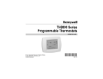
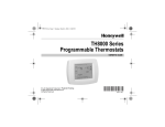
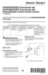
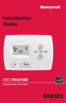
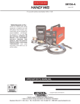
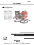
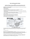
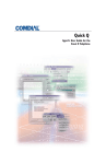
TH8110U Touch Screen
Programmable Thermostats
INSTALLATION INSTRUCTIONS
APPLICATION
The TH8110U Universal Programmable Thermostats provide electronic control of 24 Vac heating and cooling systems
or 750 mV heating system. See Table 1 for a general description.
Table 1. TH811 Thermostats Description.
Model
TH8110U
Power
Method
Batteries or
common wire
Changeover
Automatic or
manual
selectable
System Selection
Fan Selection
Heat-Off-Cool-Auto
On-Auto-Circ
Comments
System and Fan
selection vary based on
system type
RECYCLE NOTICE
If this control is replacing a control that contains
mercury in a sealed tube, do not place your old
control in the trash. Dispose of properly.
YES
Contact your local waste management authority
for instructions regarding recycling and the
proper disposal of the old control.
NO
NO
5 FEET
[1.5 METERS]
NO
INSTALLATION
When Installing this Product...
1.
2.
3.
4.
Read these instructions carefully. Failure to follow
the instructions can damage the product or cause
a hazardous condition.
Check the ratings given in the instructions to make
sure the product is suitable for your application.
Installer must be a trained, experienced service
technician.
After completing installation, use these instructions
to check out the product operation.
Selecting Location
Install the thermostat about 5 ft. (1.5m) above the floor in
an area with good air circulation at average temperature.
See Fig. 1.
® U.S. Registered Trademark
Copyright © 2004 Honeywell International Inc. •
M19925
Fig. 1. Selecting thermostat location.
Do not install the thermostat where it can be affected by:
— Drafts or dead spots behind doors and in corners.
— Hot or cold air from ducts.
— Radiant heat from sun or appliances.
— Concealed pipes and chimneys.
— Unheated (uncooled) areas such as an outside wall
behind the thermostat.
• All Rights Reserved
69-1700
TH8110U TOUCH SCREEN PROGRAMMABLE THERMOSTATS
Installing Wallplate
3.
4.
5.
CAUTION
Securely tighten each screw.
Push excess wire back into the hole.
Plug the hole with nonflammable insulation to
prevent drafts from affecting the thermostat.
Electrical Hazard.
Can cause electrical shock or equipment
damage.
Disconnect power before wiring.
HEAT PUMP
CONVENTIONAL
Y2
The thermostat can be mounted horizontally on the wall
or on a 4 in. x 2 in. (101.6 mm x 50.8 mm) wiring box.
1.
2.
Position and level the wallplate (for appearance
only).
Use a pencil to mark the mounting holes.
Y2
RC
RC
L
R
R
E
W
O/B
AUX
W2
Y
Y
S1
S1
G
G
S2
S2
C
C
SCREW TERMINALS
M19951
WALL
Fig. 3. Selecting terminal identifications for
system type.
WIRES THROUGH WALL
AND WIRE SLOT
WALL ANCHORS (2)
Table 2. Selecting Terminal Identifications for
System Type.
MOUNTING
HOLES
System Type
Standard Heat/Cool
MOUNTING
SCREWS (2)
Wallplate
Terminal
Identifications
Conventional
Wiring
Diagram
Reference
5, 6
Heat Only
Conventional
7
Heat Only with Fan
Conventional
8
Heat Only Series 20
Conventional
9
Cool Only
Conventional
10
Heat Pump with No
Auxiliary Heat
Heat Pump
11
M19916
Fig. 2. Mounting wallplate.
3.
4.
5.
Remove the wallplate from the wall and, if drywall,
drill two 3/16-in. holes in the wall, as marked. For
firmer material such as plaster, drill two 7/32-in.
holes. Gently tap anchors (provided) into the drilled
holes until flush with the wall.
Position the wallplate over the holes, pulling wires
through the wiring opening. See Fig. 2.
Insert the mounting screws into the holes and
tighten.
WIRING (FIG. 5-11)
All wiring must comply with local electrical codes and
ordinances.
1.
2.
M19917
Select set of terminal identifications (Table 2) that
corresponds with system type (conventional or
heat pump) in Fig. 3.
Loosen the screws for the appropriate system type
selected; see Table 2. Insert wires in the terminal
block under the loosened screw. See Fig. 4.
69-1700
Fig. 4. Inserting wires in terminal block.
IMPORTANT
Use 18 gauge thermostat wire.
2
TH8110U TOUCH SCREEN PROGRAMMABLE THERMOSTATS
CONVENTIONAL
CONVENTIONAL
Y2
W2
S1
S2
RC
R
W
Y
G
C
Y2
2
1
R
W2
S1
S2
C
OPTIONAL
24 VAC
COMMON
CONNECTION
3
2
1
R
C
OPTIONAL
24 VAC
COMMON
CONNECTION
3
FAN
RELAY
OUTDOOR/INDOOR
TEMPERATURE
SENSOR
RC
R
W
Y
G
C
HEAT RELAY
OUTDOOR/INDOOR
TEMPERATURE
SENSOR
COMPRESSOR
CONTACTOR
HEAT RELAY
1
POWER SUPPLY. PROVIDE DISCONNECT MEANS AND OVERLOAD
PROTECTION AS REQUIRED.
1
POWER SUPPLY. PROVIDE DISCONNECT MEANS AND OVERLOAD
PROTECTION AS REQUIRED.
2
FACTORY INSTALLED JUMPER.
2
FACTORY INSTALLED JUMPER.
3
3
OPTIONAL OUTDOOR OR INDOOR REMOTE SENSOR. AVAILABLE
ON SELECT MODELS. WIRES MUST HAVE A CABLE SEPARATE
FROM THE THERMOSTAT CABLE.
M19895
OPTIONAL OUTDOOR OR INDOOR REMOTE SENSOR. AVAILABLE
ON SELECT MODELS. WIRES MUST HAVE A CABLE SEPARATE
FROM THE THERMOSTAT CABLE.
M19897
Fig. 7. Typical hookup of heat-only system
(1H conventional).
Fig. 5. Typical hookup of conventional single-stage
heat and cool system with single transformer
(1H/1C conventional).
CONVENTIONAL
CONVENTIONAL
Y2
W2
S1
S2
3
OUTDOOR/INDOOR
TEMPERATURE
SENSOR
RC
R
W
Y
G
C
2
Y2
1
W2
S1
S2
R
C
OPTIONAL
24 VAC
COMMON
CONNECTION
HEAT RELAY
2
3
OUTDOOR/INDOOR
TEMPERATURE
SENSOR
FAN
RELAY
COMPRESSOR
CONTACTOR
RC
R
W
Y
G
C
1
1
R
C
OPTIONAL
24 VAC
COMMON
CONNECTION
FAN
RELAY
HEAT RELAY
1
POWER SUPPLY. PROVIDE DISCONNECT MEANS AND OVERLOAD
PROTECTION AS REQUIRED.
2
FACTORY INSTALLED JUMPER.
3
OPTIONAL OUTDOOR OR INDOOR REMOTE SENSOR. AVAILABLE
ON SELECT MODELS. WIRES MUST HAVE A CABLE SEPARATE
FROM THE THERMOSTAT CABLE.
M19898
C
R
1
POWER SUPPLY. PROVIDE DISCONNECT MEANS AND OVERLOAD
PROTECTION AS REQUIRED.
2
REMOVE FACTORY INSTALLED JUMPER.
3
OPTIONAL OUTDOOR OR INDOOR REMOTE SENSOR. AVAILABLE
ON SELECT MODELS. WIRES MUST HAVE A CABLE SEPARATE
FROM THE THERMOSTAT CABLE.
M19896
Fig. 8. Typical hookup of heat only system with fan
(1H conventional).
Fig. 6. Typical hookup of conventional single-stage
heat and cool system with two transformers
(1H/1C conventional).
3
69-1700
TH8110U TOUCH SCREEN PROGRAMMABLE THERMOSTATS
CONVENTIONAL
Y2
W2
S1
S2
RC
R
W
Y
G
C
CONVENTIONAL
1
R
W2
S1
S2
C
3
2
W
TR
B
TR
R
OUTDOOR/INDOOR
TEMPERATURE
SENSOR
SERIES 20
MOTOR OR
VALVE
POWER SUPPLY. PROVIDE DISCONNECT MEANS AND OVERLOAD
PROTECTION AS REQUIRED.
2
FACTORY INSTALLED JUMPER.
3
OPTIONAL OUTDOOR OR INDOOR REMOTE SENSOR. AVAILABLE
ON SELECT MODELS. WIRES MUST HAVE A CABLE SEPARATE
FROM THE THERMOSTAT CABLE.
1
R
C
OPTIONAL
24 VAC
COMMON
CONNECTION
FAN
RELAY
3
OUTDOOR/INDOOR
TEMPERATURE
SENSOR
1
RC
R
W
Y
G
C
Y2
2
COMPRESSOR
CONTACTOR
1
POWER SUPPLY. PROVIDE DISCONNECT MEANS AND OVERLOAD
PROTECTION AS REQUIRED.
2
FACTORY INSTALLED JUMPER.
3
OPTIONAL OUTDOOR OR INDOOR REMOTE SENSOR. AVAILABLE
ON SELECT MODELS. WIRES MUST HAVE A CABLE SEPARATE
FROM THE THERMOSTAT CABLE.
M19900
M19899
Fig. 10. Typical hookup of cool only system
(1C conventional).
Fig. 9. Typical hookup of heat only Series 20 system.
HEAT PUMP
Y2
RC
2
L
R
E
O/B
AUX
Y
S1
G
S2
C
1
R
C
3
OPTIONAL
24 VAC
COMMON
CONNECTION
FAN RELAY
4
OUTDOOR/INDOOR
TEMPERATURE
SENSOR
CHANGEOVER
VALVE
COMPRESSOR
1 POWER SUPPLY. PROVIDE DISCONNECT MEANS AND OVERLOAD PROTECTION AS REQUIRED.
2 FACTORY INSTALLED JUMPER.
3 "O/B" TERMINAL SET TO CONTROL AS EITHER "O" OR "B" IN THE INSTALLER SETUP.
4 OPTIONAL OUTDOOR OR INDOOR REMOTE SENSOR. AVAILABLE ON SELECT MODELS.
WIRES MUST HAVE A CABLE SEPARATE FROM THE THERMOSTAT CABLE.
M19903
Fig. 11. Typical hookup of single-stage heat pump with no auxiliary/backup heat (1H/1C heat pump).
Powering the Thermostat
system, use the common from the cooling transformer to
connect to C screw and remove the jumper wire between
the R and Rc screws.
There are two different ways to power the thermostat:
• Batteries (three AAA alkaline).
• 24 Vac Common wire.
Inserting Batteries (Optional)
If not using a 24 Vac Common to power the thermostat,
install three AAA alkaline batteries (included) in the back
of the thermostat. Make sure the positive and negative
terminals are oriented correctly, as marked on the device.
See Fig.12.
Wiring 24 Vac Common
Wire the common side of the transformer to the C screw
of the thermostat wallplate. When installing in a single
transformer system, keep jumper wire between the R
and Rc screws. When installed in a two-transformer
69-1700
4
TH8110U TOUCH SCREEN PROGRAMMABLE THERMOSTATS
BATTERIES (3)
REMOVE DURING
INSTALLATION
REMOVE DURING
INSTALLATION
REMOVE TAB TO ACTIVATE REAL TIME CLOCK
M19918
M19920
Fig. 12. Installing batteries on thermostat back.
Fig. 14. Removing tab to activate real-time clock.
Mounting the Thermostat
1.
2.
This thermostat is designed to automatically keep current
time and day in memory for up to ten years under normal
use after calendar is set. When thermostat is first
powered, display is ready to enter calendar date (Fig.15).
Align the terminal screw blocks with the pins on the
back of the thermostat.
Push the thermostat straight onto the wallplate.
See Fig. 13.
SET CURRENT DAY
SET MONTH
WALL
MON
TUE
WED
D
THU
FRI
RI
SAT
AT
SUN
DONE
REMOVE DURING
INSTALLATION
USE ARROWS TO SET YEAR AND TIME
MON
WED
W
THU
FRI
SAT
AT
SUN
OK TO PICK MULTIPLE
U
DAYS SCREEN LOCKED
CHANGE FILTER
R UV LAMP HUMIDIFIER PAD
M19919
Fig. 13. Mounting thermostat on wallplate.
DONE
Adjusting Real-Time Clock
M19921
Setting Calendar and Time
Fig. 15. Setting calendar and time after initial
powerup.
Locate and remove the tab labeled Remove in the lower
left corner on the thermostat back. The tab must be
removed to activate the real-time clock. See Fig. 14.
IMPORTANT
The tab on back of thermostat in lower-left
corner must be removed to activate this feature.
Using the Thermostat
The thermostat has a touch screen interface. Words or
symbols appear, highlighting keys, as needed, to
complete tasks. Press keys with your fingertips. Sharp
tips on pens or pencils can damage thermostat.
1.
2.
3.
4.
5
Use arrow keys to set Year, Month and Day (see
Fig. 15).
Press Done key.
Use arrow keys to set current time. See Fig. 15.
Press Done key.
69-1700
TH8110U TOUCH SCREEN PROGRAMMABLE THERMOSTATS
OPERATION
Entering Installer Setup
1.
System and Fan Settings
2.
The System default setting is Heat and the Fan default
setting is Auto.
3.
SYSTEM Settings
Heat: Thermostat controls heating system.
Off: Both heating and cooling are off.
Cool: Thermostat controls cooling system.
Auto: Thermostat automatically changes between
heating and cooling systems, depending on indoor
temperature. (See Installer Setup section.)
Thermostat must be powered either with Alkaline
AAA batteries or with 24 Vac Common wire.
From the home screen, press System key. (Press
Done or Cancel key to return to home screen.)
Five blank touch keys show on the bottom of the
screen between the Done and Cancel keys. Press
and hold the two blank keys on either side of the
center blank key for approximately five seconds
until screen changes. See Fig. 16.
TUE
MON
WED
THU
Inside
FAN Settings
SAT
AT
SUN
Following
Schedule
SYSTEM
EM HEAT
The Fan setting can be programmed into the thermostat
schedule for each period (Wake, Leave, Return, Sleep).
See the Owners’ Guide for additional information.
FRI
Set To
OFF
COOL
PM
DONE
CANCEL
Preprogrammed Settings
Table 3 shows the default program settings. See Owners’
Guide for complete instructions on changing the
program.
Table 3. Default Program Settings.
Schedule
Period
Setpoints
Time
Heat
Cool
M19923
Fan
Setting
Wake
6:00AM
70°F
(21°C)
78°F
(25.5°C)
Auto
Leave
8:00AM
62°F
(16.5°C)
85°F
(29.5°C)
Auto
Return
6:00PM
70°F
(21°C)
78°F
(25.5°C)
Auto
82°F
(28°C)
Auto
Sleep
10:00PM 62°F
(16.5°C)
Fig. 16. Entering Installer Setup.
4.
The Installer Setup Number is displayed in the
lower left. It is a four-digit code beginning with zero.
The factory setting or other choice selection is displayed in the lower right. See Fig. 17. This is a twodigit code shown in the Option column of Table 4.
ADVANCE TO NEXT
INSTALLER SETUP
INSTALLER
SETUP NUMBER
MON
INSTALLER SETUP
This Universal Thermostat works with many different
system types. To operate correctly, the thermostat must
be set up to operate the installed heating and/or cooling
system.
FACTORY
SETTING
WED
THU
U
FRI
SAT
AT
SUN
DONE
O
Installer Setup Menus
Main Menu: Offers the most commonly used options.
It is necessary to enter this menu to set the
thermostat to the type of system it is operating. Many
applications use only the Main Menu.
PRESS TO EXIT
INSTALLER SETUP
M19922
Fig. 17. Installer Setup Number and factory setting
selection locations.
Regional Menu: Offers choices often changed due to a
particular area or region. For example, temperature
display in Fahrenheit or Celsius is offered in this menu.
Changing Installer Setup Selections
1.
Advanced Settings Menu: Offers more settings to fully
customize the thermostat. Many of these settings do not
require changing from the factory settings.
69-1700
CHANGE THE
FACTORY
SETTING
2.
6
Advance to the next Installer Setup Number by
pressing the up and down arrow keys to the right of
the four-digit Installer Setup Number. See Fig. 17.
Change the factory Setting Options by pressing the
up and down arrow keys right of the two-digit code
selection. See Fig. 17.
TH8110U TOUCH SCREEN PROGRAMMABLE THERMOSTATS
Exiting Installer Setup
1.
IMPORTANT
The three Installer Setup Menus (Tables 4-6)
show all available options. These options customize themselves as you make selections to
Installer Setup. So not all Installer Setup
Selections are shown or are available to
change.
Press Done key to exit Installer Setup screen.
Table 4. Main Installer Setup Menu.
Factory Setting
Select
Installer
Setup
Number
Option
Description
Other Choices
Options
—
Date (Year
Upper)
0120
20
Set first two digits of 21
current calendar
year (20 for year
2005, etc)
21 —first two digits of
2000 -2178
current calendar year (21xx) available
Date (Year
Lower)
0130
04
Represents last two 00 -99
digits of current
calendar year
(2004).
Select last two digits of
current calendar year.
2001-2178
available
Date (Month) 0140
6
Digit(s) represents
current calendar
month.
1-12
Select number that
represents current calendar
month.
—
Date
(Day)
0150
15
Digit(s) represents
current calendar
date.
1-31
Select number that
—
represents current calendar
date.
Schedule
Options
0160
4
7-day programming 0
0 —nonprogrammable
—
System Type
Selection
0170
1
1 Heat/1 Cool
Conventional
System
1—1 heat/1 cool
2—single-stage heat pump
(no aux. heat)
3—heat only (no fan)
4 —heat only (with fan)
5—hot water Series 20
(3-wire or normally open
zone valves)
6—cool only
Available options
and defaults vary
by thermostat.
System selection
automatically
modifies some
default settings
and/or hides other
Installer Setup
options.
Fan Operation 0180
0
Conventional
1
applications where
equipment controls
fan operation in
heat mode.
Heat pump or electric heat
applications where
thermostat controls fan
operation in heat mode.
Only shown if
conventional
system is
selected. If heat
pump is chosen,
fan defaults to
electric.
Reversing
Valve (O/B)
Operation
0
O/B terminal is
energized for
reversing valve in
cooling
1
O/B terminal is energized for Only shown if
reversing valve in heating
heat pump
system is chosen.
7
69-1700
1-6
—
Comments
1 thru 0099 —
0190
—
Description
Not used.
—
TH8110U TOUCH SCREEN PROGRAMMABLE THERMOSTATS
Table 4. Main Installer Setup Menu. (Continued)
Factory Setting
Select
Installer
Setup
Number
Option
Description
Other Choices
Options
Description
Comments
Cycles per
0220
hour (cph) for
1st Stage
Compressor
3
Compressor Stage
1 cycles per hour
(cph)
1-6
1-6 available;
3 is recommended.
—
Cycles per
0240
hour (cph) for
1st Stage
Conventional
Heat
5
Conventional Heat
Stage 1 cycles per
hour (cph)
1-12
1-12 available; typical
settings:
1—1 cph used for steam or
gravity system.
3—3 cph used for hot water
systems or high efficiency
(90% or better) fossil fuel
forced air systems.
5—5 cph used for standard
fossil fuel forced air
systems.
9—9 cph used for electric
forced air heat systems.
Not shown if
system selection
is heat pump.
Selection in this
stage changes
default cph for
2nd stage heat.
Continuous
Backlight
0280
0
Backlight not on
1
continuously.
Thermostat
backlight comes on
with each key
press.
Backlight is on continuously
(thermostat must have a
common wire attached for
this function).
Option is always
shown; however,
continuously on
backlight works
only if thermostat
is wired with 24
vac Common.
Additional
0290
Menu Choices
0
Only main menu
1,2
options are shown.
Installer Test
Options shown next
(Table 7).
1—Main Menu and Regional
Settings are shown plus
Installer Test (Tables 5 and 7
only).
The majority of
application
require only the
Main Menu
Options.
2—All remaining Menu/
Options shown plus Installer
Test (Tables 5, 6 and 7).
69-1700
8
TH8110U TOUCH SCREEN PROGRAMMABLE THERMOSTATS
Table 5. Regional Settings Menu.
Select
Installer
Setup
Number
Factory Setting
Option
Other Choices
Description
Options
Description
Comments
Changeover
0300
0
Manual changeover
1
1—auto
changeover
—
Deadband
0310
3
Heating and cooling
setpoints can be set
no closer than 3°F
(1.5°C)
2 thru 9
Heating and
cooling setpoints
can be set no
closer than
chosen value:
2—2°F (1°C)
3—3°F (2°C)
4—4°F (2.5°C)
5—5°F (3°C)
6—6°F (3.5°C)
7—7°F (4°C)
8—8°F (4.5°C)
9—9°F (5°C)
Shown only if
automatic
changeover is
selected.
Temperature
Indication
Scale
0320
0
Temperature is
displayed in °F.
1
Temperature is
displayed in °C.
—
Daylight
Savings
0330
1
Daylight savings
enabled (United
States).
0
0—daylight savings Set to 0 in areas that
is disabled.
do not follow
daylight savings.
Remote
Temperature
Sensor
(Outdoor or
Indoor)
0340
0
No remote
temperature sensor
1,3
1—outdoor
temperature sensor
for display only.
3—indoor
temperature sensor
9
Defaults and
Options depend on
System Type
selected. Indoor
Temperature Sensor
uses an averaging
network and does
not include on-board
sensor.
69-1700
TH8110U TOUCH SCREEN PROGRAMMABLE THERMOSTATS
Table 6. Advanced Settings Menu.
Select
Installer
Setup
Number
Factory Setting
Option
Description
Other Choices
Options
Description
Comments
Furnace Filter 0500
Change
Reminder
0
Furnace filter
1-6
change reminder
off
1—10 run time days
2—30 run time days
3—60 run time days
4—90 run time days
5—120 run time days
6—365 run time days
Run time based on
call for fan.
Humidifier Pad 0510
Replacement
Reminder
0
Humidifier pad
replacement
reminder off
1-3
1—90calendardays
2—180calendardays
3—365 calendar days
—
UV Lamp
Replacement
Reminder
0520
0
UV Lamp
replacement
reminder off
1
1—365 calendar days
—
Adaptive
Intelligent
Recovery™
0530
1
0
Adaptive
Intelligent
Recovery™
control is
activated (system
starts early so
setpoint is
reached by start
of program
period).
0—conventional
—
recovery (system starts
recovery at
programmed time)
Number of
Periods
0540
4
Four periods
2
available (Wake,
Leave, Return,
Sleep)
Two periods availbable
(Wake and Sleep)
Not shown in nonprogrammable is
selected. 2 or 4
applies to all days of
the week.
Minimum
Compressor
Off Time
0580
5
Five minute
0, 2, 3, 4
minimum off time
for compressor
Minimum number of
minutes compressor is
off between calls for
compressor
—
Heat
Temperature
Range Stop
0600
90
Highest heating
setpoint.
40 to 89
Temperature range (1°F Shown in 1/2 °C.
increments) of heating
setpoint.
Cool
Temperature
Range Stop
0610
50
Lowest cooling
setpoint.
51 to 99
Temperature range (1°F Shown in 1/2 °C.
increments) of cooling
setpoint.
Clock Format
0640
12
12-hour clock
format
24
24-hour clock format
—
Extended Fan 0650
on time Heat
0
No extended fan 90
operation after
call for heat ends
Fan operation is
extended 90 seconds
after call for heat ends.
Not shown if fan
operation is set to
fossil fuel or in Cool
Only Systems
Extended Fan 0660
on time Cool
0
No extended fan 90
operation after
call for cool ends
Fan operation is
extended 90 seconds
after call for cool ends.
Not shown in Heat
Only Systems.
69-1700
10
TH8110U TOUCH SCREEN PROGRAMMABLE THERMOSTATS
Table 6. Advanced Settings Menu. (Continued)
Select
Keypad
Lockout
Installer
Setup
Number
Factory Setting
Option
Description
Other Choices
Options
Description
Comments
0670
0
Unlocked keypad 1, 2
1—partially locked
keypad
2—fully locked keypad
Unlocked—all
functions are
available.
Partially locked—
only temperature up
and down keys and
ability to enter and
modify Installer
Setup mode are
available.
Fully locked—only
ability to enter and
modify Installer
Setup mode are
available.
Temperature
0680
Control in Heat
2
Standard
1, 3
temperature
control in heating
1—less aggressive
temperature control
(could cause
temperature
undershoot)
3—more aggressive
temperature control
(could cause
temperature overshoot)
Applies to recovery
ramp and use of
auxiliary heat during
recovery.
Choose 1 if getting
temperature
overshoot.
Choose 3 if getting
temperature
undershoot.
Temperature
0690
Control in Cool
2
Standard
1, 3
temperature
control in cooling
1—less aggressive
temperature control
(could cause
temperature
undershoot)
3—more aggressive
temperature control
(could cause
temperature overshoot)
Applies to recovery
ramp.
—
Choose 1 if getting
temperature
overshoot.
Choose 3 if getting
temperature
undershoot.
Temperature
0700
Display Offset
0
No difference in
-3, -2, -1,
displayed
0, 1, 2, 3
temperature and
actual room
temperature
-3°F (-1.5°C)
-2°F (-1°C)
-1°F (-.5°C)
0 F (0.°C)
1°F (.5°C)
2°F (1°C)
3°F (1.5°C)
Reset
Thermostat
0
No thermostat
reset.
Resets all Installer
Only calendar
Setup Options to default settings and time are
values and resets
retained.
schedule to default
setting.
0710
1
SYSTEM CHECKOUT
ADVANCED FEATURES
Installer System Test
Outdoor or Indoor Temperature Sensor
The Installer System Test mode is used to test the HVAC
system(s). See Table 7. While in System Test mode,
minimum off -time for compressors is bypassed.
Allow outdoor or indoor temperature sensor to absorb the
air for a minimum of five minutes before taking a reading.
See the Sensor instructions for more information.
The Installer Test is part of Installer Setup options. Enter
Installer Setup screen and press Down arrow key to bring
up test selection(s) quickly. See Fig. 16.
11
69-1700
TH8110U TOUCH SCREEN PROGRAMMABLE THERMOSTATS
CAUTION
Equipment Damage Hazard.
Minimum compressor off-time is bypassed
during Installer System Test.
Avoid cycling compressor quickly.
Table 7. System Test(s).
Installer
Setup
Number
Select
Factory Setting
Options
Description
Other Choices
Options
Description
Installer Test
Cool
Test 1
0
Cool is off
1
0—cool off
1—cool stage 1
turns on
Installer Test
Fan
Test 2
0
Fan is off
1
0—fan off
1—fan turns on
Installer Test
Heat
Test 3
0
Heat is off
1
0—heat off
1—stage 1heat on
Comments
System selection determines tests available and
number of stages shown.
TROUBLESHOOTING (SEE TABLE 8)
Table 8. Troubleshooting.
Symptom
Possible Cause
Action
Display does not come on.
Thermostat is not being
powered.
Check for 24 Vac between C and Rc.
Verify AAA batteries installed correctly and good.
Temperature settings do not
change.
The upper or lower
temperature limits were
reached.
Check temperature setpoints.
Check Installer Setup Numbers 0600 and 0610;
modify.
The keypad is fully locked.
Check Installer Setup Number 0670 to change keypad
lock options.
Thermostat minimum offtime is activated.
Wait up to five minutes for the system to respond.
Heating or cooling does not
come on.
System selection is not set to Set system Selection to correct position.
Heat or Cool.
O/B terminal is not set
Check Installer Setup Number 0190 and set correctly.
correctly (Heat Pumps only).
System type Selection is
incorrect.
Check Installer Setup Number 0170 and make sure
correct System type is chosen.
Thermostat is calling for Heat
Heating or cooling
(Heat on) or Cool (Cool on) but equipment is not operating.
no heating or cooling is running.
Check wiring.
Check Installer Setup Number 0170; verify correct
system type is chosen.
Verify equipment operation in System Test mode.
Thermostat does not respond
when touchpad is pressed.
Check Installer Setup Number 0670 to change keypad
locked options.
The keypad is locked.
Automation and Control Solutions
Honeywell International Inc.
1985 Douglas Drive North
Golden Valley, MN 55422
69-1700
G.H.
03-04
Honeywell Limited-Honeywell Limitée
35 Dynamic Drive
Scarborough, Ontario
M1V 4Z9
www.honeywell.com/yourhome