1
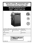
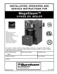
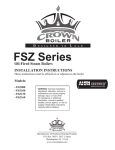
L404F,T,V
PressureTrol® Controllers
PRODUCT DATA
FEATURES
• Models available in a series of control ranges, and
pressure scales in kPa and psi.
• All models automatically reset and have an adjustable
differential.
• Models have snap switch to open or close a circuit on
a pressure rise.
• Case has a clear plastic cover so setpoints can be
observed.
• 1/4 inch—18 NPT connection for pipe on diaphragm
assembly.
• Ground screw terminal.
L404F:
• Controllers may be used with steam, air, or
noncombustible gases, or fluids noncorrosive to the
pressure sensing element.
L404T:
APPLICATION
L404F PressureTrol® Controllers provide operating control
with automatic limit protection for pressure systems of up to
2070 kPa, or 300 psi.
• High pressure limits, break a circuit on oil pressure
rise above setpoint.
L404V:
• Low pressure limits, makes a circuit on oil pressure
rise above setpoint.
L404T,V PressureTrol® Controllers are for use on oil burner
systems for pressures up to 1035 kPa or 150 psi.
Contents
Application ........................................................................
Features ...........................................................................
Specifications ...................................................................
Ordering Information ........................................................
Installation ........................................................................
Settings and Adjustments .................................................
Checkout ..........................................................................
® U.S. Registered Trademark
© 2004 Honeywell International Inc.
All Rights Reserved
1
1
2
2
3
6
7
71-2429—2
L404F,T,V PRESSURETROL® CONTROLLERS
SPECIFICATIONS
Model:
L404F,T,V PressureTrol® Controllers. See Table 1.
Table 1. Models with kPa—psi.
kPa
Model Number
L404F1060
psi
15 to 100
2 to 15
L404F1078
35 to 350
L404F1094
140 to 2070
L404F1102
Maximum Diaphragm
pressure
Subtractive Differentiala
Operating Ranges
kPa
psi
15 to 40
2 to 6
5 to 50
40 to 100
20 to 300
140 to 345
kPa
psi
170
25
6 to 14
590
85
20 to 50
2410
350b
70 to 1035
10 to 150
70 to 150
10 to 22
1550
225
c
L404F1219
15 to 100
2 to 15
15 to 40
2 to 6
170
25
L404F1243c
35 to 350
5 to 50
40 to 100
6 to 14
590
85
L404F1227c
70 to 1035
10 to 150
70 to 150
10 to 22
1550
225
L404F1235c
140 to 2070
20 to 300
140 to 345
20 to 50
2410
350b
L404F1300c
415 to 1240
60 to 180
40 fixed
6.0 Fixed
1550
225
25
L404F1326
0 to 100
0 to 15
15 to 40
2 to 6
170
L404F1334
0 to 350
0 to 50
40 to 100
6 to 14
590
85
L404F1342
35 to 1000
5 to 145
70 to 150
10 to 22
1550
225
L404F1359
70 to 2000
10 to 290
140 to 345
20 to 50
2410
350b
L404F1367
7 to 55
1 to 8
5 to 14
0.75 to 2
170
25
L404F1375d
35 to 350
5 to 50
40 to 100
6 to 14
590
85
L404F1383d
70 to 1035
10 to 150
70 to 150
10 to 22
1550
225
L404F1391d
140 to 2070
20 to 300
140 to 345
20 to 50
2410
350b
L404F1409d
15 to 100
2 to 15
15 to 40
2 to 6
170
25
L404T1055
35 to 350
5 to 50
40 to 100
6 to 14
590
85
L404T1063
70 to 1035
10 to 150
70 to 150
10 to 22
1550
225
L404V1087
70 to 1035
10 to 150
70 to 150
10 to 22
1550
225
L404V1095d
35 to 350
5 to 50
40 to 100
6 to 14
590
85
d
a Nominal
at midscale operating range.
Brass bellows instead of stainless steel diaphragm.
c
Models with 1/4-19 BSPT thread instead of 1/4-18 NPT thread.
d
Make-on-rise models with terminal B omitted for miswiring compliance.
b
ORDERING INFORMATION
When purchasing replacement and modernization products from your TRADELINE® wholesaler or distributor, refer to the
TRADELINE® Catalog or price sheets for complete ordering number.
If you have additional questions, need further information, or would like to comment on our products or services, please write or
phone:
1. Your local Honeywell Automation and Control Products Sales Office (check white pages of your phone directory).
2. Honeywell Customer Care
1885 Douglas Drive North
Minneapolis, Minnesota 55422-4386
In Canada—Honeywell Limited/Honeywell Limitée, 35 Dynamic Drive, Scarborough, Ontario M1V 4Z9.
International Sales and Service Offices in all principal cities of the world. Manufacturing in Australia, Canada, Finland, France,
Germany, Japan, Mexico, Netherlands, Spain, Taiwan, United Kingdom, U.S.A.
71-2429—2
2
L404F,T,V PRESSURETROL® CONTROLLERS
Table 2. Conversion Table.
Operating Range Conversions
kg/cm2
0.1 to 1.05
Subtractive Differential Conversions
kPa
kg/cm2
psi
15 to 100
2 to 15
0.15 to 0.4
kPa
psi
15 to 40
2 to 6
0.4 to 3.5
35 to 350
5 to 50
0.4 to 1.0
40 to 100
6 to 14
0.7 to 10.0
70 to 1035
10 to 150
0.7 to 1.6
70 to 150
10 to 22
1.5 to 20.0
140 to 2070
20 to 300
1.5 to 3.5
150 to 300
20 to 50
Mounting Means: 1/4 inch-18 NPT connection on diaphragm
assembly; or surface mounts using holes in back of case.
Table 3. Switch Ratings (Amperes).
Switch State
120 Vac
240 Vac
Dimensions: See Fig. 1.
Full Load
8.0
5.1
Locked Rotor
48.0
30.6
Pressure Sensing Element: Stainless steel diaphragm (140
to 2070 kPa models) has brass bellows.
Maximum Ambient Temperature: 66°C (150°F). Also, refer
to note under Mounting.
Adjustment Means: Screws on top of control case. Scales
are marked in psi or kPa.
3-1/4 (83)
Switching Action: Snap switch breaks R-B (closes R-W) on
pressure rise. Make-on-rise devices omit terminal B.
Grounding Means: Ground screw terminal marked with a
circled ground symbol.
Accessories:
14026 Steam Trap (118023 for BSPT models).
33312B Knurled Knob—fits on top of adjusting screws.
129564 Range Stop—range stop screw, Part No. 107194, and
wrench, Part No. 23466, to limit setpoint range.
4-1/2 (115)
1
4-11/32 (111)
2-3/4 (70)
1-61/64 (50)
DIFFERENIAL
ADJUSTMENT
SCREW
3-7/8
(99)
HOLE FOR
1/2 INCH
CONDUIT
DIMENSION
"A"
(SEE TAB)
3-3/4
(95)
1-3/16
(30)
PSI
RANGE
2 TO 15
5 TO 50
10 TO 150
20 TO 300
13/16 (21)
MAIN SCALE
ADJUSTMENT
SCREW
3/16 X 11/32
(5 X 9)
KNOCKOUT
DIMENSION
"A"
123
126
126
146
1-15/16 (49)
1-13/16
(46)
CLEAR
PLASTIC
COVER
1-1/16 (27)
1/4 –18 NPT
2-1/8 (54)
1
1-1/2 (38)
1
15 TO 100 kPa (2 TO 15 PSI) SCALE MODELS ONLY.
M19635B
Fig. 1. L404F,T,V approximate dimensions in inches (millimeters in parentheses).
INSTALLATION
3.
When Installing This Product…
1.
2.
Read these instructions carefully. Failure to follow them
could damage the product or cause a hazardous
condition.
Check on the ratings given in the instructions and
3
4.
marked on the product to make sure the product is
suitable for your application.
Installer must be a trained, experienced service
technician.
After installation is complete, check out the product
operation as provided in these instructions.
71-2429—2
L404F,T,V PRESSURETROL® CONTROLLERS
Remote Mounting
IMPORTANT
When making pipe connections, use pipe dope
sparingly to seal the joints; any excess dope may
clog the small hole in the fitting and prevent the
controller from operating properly.
Excessive vibration at the boiler may affect the operation of
the L404F. In these cases, the L404F should be remotely
located, subject to the following:
1.
Location and Mounting (L404F)
Locate the L404F where the ambient temperature will not
exceed 66°C (150°F). The L404F can be mounted near the
pressure gauge, at a remote location, in a fitting provided by
the boiler manufacturer, or in a special mounting on low water
cutoffs. The L404F should always be mounted above the
water line in steam boiler applications.
NOTE: For accurate operation, supplemental heat should be
added to installations where temperatures fall below
-29°C (-20°F).
A steam trap must be connected between the L404F and the
boiler (see Fig. 2) to prevent boiler scale and corrosive vapors
from attacking the elbows or diaphragm.
PRESSURE
CONTROLLER
PRESSURE
GAUGE
1
14026
STEAM TRAP
(SIPHON LOOP)
Location and Mounting (L404T,V)
Location
Mount the oil pressure controller directly on the main pipe.
Insert a tee in the pipe line, and connect a pipe nipple of
appropriate size to the tee (see Fig. 4). Screw the hexagonal
fitting (1/4-18 NPT internal thread) of the pressure controller to
the pipe nipple. To avoid leaks and damage to the case, use a
parallel jaw wrench on the hexagonal fitting close to the pipe
nipple. Do not tighten the pressure controller by hand by
holding the case.
1/4 IN. BLACK IRON PIPE WITH 1/4 - 18 NPT EXTERNAL
THREADS ON BOTH ENDS AND 2-1/4 IN. DIAMETER LOOP.
M8934B
Fig. 2. Steam trap mounting.
Pressure Gauge Mounting
To mount beside a pressure gauge, remove the gauge, and
install in its place the steam trap with a tee on top. Mount the
PressureTrol® unit and pressure gauge on the side of the tee
by means of nipples and elbows (see Fig. 2).
MAIN
OIL
LINE
If it is not convenient to mount the L404F adjacent to the
pressure gauge, install a steam trap at the location
recommended by the boiler manufacturer, then screw the
device directly to the steam trap.
Mounting
BOILER
1
Boiler Mounting
NOTE: For most accurate operation, supplemental heat
should be added to installations where the
temperature falls below -20°F (-29°C).These
controllers can be mounted at any location in the oil
supply line, depending on the application. Typical
locations are shown in Fig. 3. The low oil pressure
controller should be located upstream from the
safety shutoff valve(s). In a downstream location,
there would be zero pressure when the burner is not
running and the safety shutoff valve(s) is (are)
closed. This could prevent startup or require manual
reset every time the burner is started. The high oil
pressure controller should be located as near to the
burner as possible.
TEE
4-1/2 TO 5-1/2
(114.3 TO 139.7)
2.
3.
All piping must be suitable and properly pitched to drain
all condensation back to the boiler.
The remote mounting must be solid.
A steam trap must be used at one end of the piping.
Make all pipe connections in accordance with approved
standards. Use only a small amount of pipe compound to seal
the connection joints. Excess pipe compound may clog the
orifice in the pipe fitting and prevent the controller from
operating properly.
STRAINER
MANUAL
SHUTOFF
VALVE
OIL
PUMP WITH
PRESSURE RELIEF
ATOMIZER
LOW OIL
LOW OIL
PRESSURE
TEMPERATURE RECIRCULATING
CONTROLLER
VALVE AND SAFETY
SHUTOFF VALVE
HIGH OIL
PRESSURE
CONTROLLER
MANUAL
SHUTOFF
VALVE
ATOMIZING MEDIUM
(AIR OR STEAM)
Fig. 3. Typical locations of pressure controllers in an oil burner system.
71-2429—2
4
TO OIL
BURNER
M17861
L404F,T,V PRESSURETROL® CONTROLLERS
All wiring must comply with applicable codes and ordinances.
All models have terminals (on the MicroSwitch® snap-acting
switch) inside the cover and knockouts for conduit and cable.
Refer to manufacturer installation and wiring instructions, if
available, and to typical hookups shown in Fig. 6 to 10.
OIL PRESSURE
CONTROLLER
(AT RIGHT
ANGLES TO THE
MAIN PIPE LINE)
L404F PRESSURETROL
HEXAGONAL
FITTING
R
2
W
PIPE NIPPLE
B
PIPE
WRENCH
MAIN TEE
(TURN TO LEVEL
THE CONTROLLER)
24 VOLT RELAY
L1
POWER (HOT)
SUPPLY
L2
1
MAIN PIPE LINE
M17860
24 VOLT
POWER
SUPPLY
Fig. 4. Mounting an oil pressure controller
directly on the main pipe.
1 PROVIDE DISCONNECT MEANS AND OVERLOAD PROTECTION
AS REQUIRED.
Using with Preheated Oil
When used with preheated oil, a siphon loop (part number
14026) must always be connected between the controller and
the main pipe (see Fig. 5) to provide thermal buffering.
2 AS SHOWN, SWITCH OPENS ON PRESSURE RISE. REVERSE
ACTING (MAKE ON PRESSURE RISE) UNITS ARE WIRED TO
R-W TERMINALS AND TERMINAL B IS OMITTED.
M19637A
Fig. 6. L404F in low voltage relay circuit.
OIL PRESSURE
CONTROLLER
LINE VOLTAGE
THERMOSTAT
L404F PRESSURETROL
2
R
4-1/2
TO
5-1/2
(114 TO
140)
W
B
14026
SIPHON LOOP 1
TEE
MOTOR
PREHEATED OIL SUPPLY LINE
1
L1
L2
(HOT)
POWER
SUPPLY 1
1/4 INCH BLACK IRON PIPE WITH 1/4-18 NPT EXTERNAL THREADS ON
BOTH ENDS AND 2-1/4 IN. (57 MM) DIAMETER LOOP.
M17858A
Fig. 5. Mounting of a siphon loop, with approximate
dimensions in in. (mm).
1 PROVIDE DISCONNECT MEANS AND OVERLOAD PROTECTION
AS REQUIRED.
2 AS SHOWN, SWITCH OPENS ON PRESSURE RISE. REVERSE
ACTING (MAKE ON PRESSURE RISE) UNITS ARE WIRED TO
R-W TERMINALS AND TERMINAL B IS OMITTED.
WIRING
M19638A
Fig. 7. L404F in a typical 2-wire control circuit.
WARNING
Electrical Shock Hazard.
Can cause severe injury, death or property
damage.
Disconnect the power supply before beginning wiring.
More than one power supply disconnect may be
required.
5
71-2429—2
L404F,T,V PRESSURETROL® CONTROLLERS
B R-W
B R-W
CONTROL
SET POINT
B-R BREAKS
(R-W MAKES)
R
R
W
B
W
B (OMITTED)
DIFFERENTIAL
(ADJUSTABLE)
B-R MAKES
(R-W BREAKS)
B-R W
L404T
BREAKS ON PRESSURE
RISE TO SET POINT
SWITCH ACTION ON
PRESSURE RISE
L404V
MAKES ON PRESSURE
RISE TO SET POINT
B-R W
SWITCH ACTION ON
PRESSURE FALL
INDICATES CLOSED SWITCH CONTACTS.
M1801B
Fig. 8. L404T,V terminal blocks and internal schematics.
M19639B
Fig. 11. Operation of switch on pressure rise and fall.
Setpoint Adjustment
FLAME
SAFEGUARD
CONTROL
OIL PRESSURE
CONTROLLER
MAIN OIL VALVE
SOLENOID
Turn the pressure adjusting screw on the top of the controller
(Fig. 12) to adjust the setpoint. Turn the differential adjusting
screw to the desired pressure difference between switch
opening and switch closing.
L2
M9789
NOTE: When the main scale setting is at the lower end of
the operating range, the differential range will be less
than the differential setting by approximately 20
percent.
Fig. 9. Hookup of an oil pressure controller used on a
single burner system with an integral oil pump.
OIL PRESSURE
CONTROLLER
OTHER
CONTROLLERS,
LIMITS, AND
INTERLOCKS
DIFFERENTIAL
ADJUSTING SCREW
L1
(HOT)
L2
L2
GROUND SCREW
SCALEPLATES
FLAME
SAFEGUARD
CONTROL
PRESSURE ADJUSTING SCREW
MAIN SCALE
PRESSURE
INDICATOR
M9790
Fig. 10. Hookup of an oil pressure controller used on a
single burner or multiburner system with an external oil
pump.
DIFFERENTIAL
SETTING
INDICATOR
SETTINGS AND ADJUSTMENTS
When the pressure at the control rises above the L404
setpoint, a circuit opens between the R-B terminals. During a
pressure fall, R-B will close at the setpoint pressure minus the
switch differential.
For example, if a controller is set to differential B (see Fig.11)
with a controller setpoint of A, R-B will open when the
pressure rises to A. Then during a pressure fall, the R-B
terminals will close when the pressure drops to C (A minus
differential B).
For make on rise applications, the switch is wired to R-W
terminals. The R-W circuit will close on pressure rise to the
setpoint. R-W will open again on a pressure drop past the
switch differential.
71-2429—2
DIAPHRAGM
ASSEMBLY
OPERATING
LEVER
M19640A
Fig. 12. view of L404 PressureTrol® Controller.
Scaleplate Adjustment
The L404F,T,V has been carefully calibrated during
manufacture and should not require recalibration.
However, if recalibration is necessary, remove the cover and
loosen the setscrews which hold the scaleplate. Adjust the
plate up or down, as required, to bring the device into
calibration. Tighten the setscrews securely and replace the
cover.
6
L404F,T,V PRESSURETROL® CONTROLLERS
CHECKOUT
After the controller has been installed, wired and adjusted, it
should be tested with the system in operation. First, allow the
system to stabilize. Then, observe the operation of the
controller while raising and lowering its setpoint. Pressure
should increase when the setpoint is raised and decrease
when the setpoint is lowered.
7
Also, check the make and break points of the controller. If they
do not agree with a separate, accurately calibrated pressure
gauge, a slight adjustment of the scaleplate(s) may be
necessary.
Use accurate pressure testing equipment when checking out
the controller. Do not rely on inexpensive gauges. The
controllers are carefully calibrated at the factory.
71-2429—2
Automation and Control Solutions
Honeywell International Inc.
1985 Douglas Drive North
Golden Valley, MN 55422
Honeywell Limited-Honeywell Limitée
35 Dynamic Drive
Scarborough, Ontario
M1V 4Z9
71-2429—2 G.R. Rev. 09-04
www.honeywell.com