1
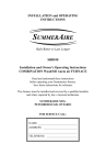
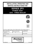
D
E S I G N E D
T O
L
E A D
FSZ Series
Oil-Fired Steam Boilers
Installation Instructions
These instructions must be affixed on or adjacent to the boiler
Models:
• FSZ080
• FSZ100
• FSZ130
• FSZ160
Warning: Improper installation,
adjustment, alteration, service or
maintenance can cause property
damage, injury, or loss of life.
For assistance or additional
information, consult a qualified
installer, service agency or the oil
supplier. Read these instructions
carefully before installing.
Manufacturer of Hydronic Heating Products
P.O. Box 14818 3633 I. Street
Philadelphia, PA 19134
www.crownboiler.com
WARNINGS FOR THE HOMEOWNER
FOLLOW ALL INSTRUCTIONS and warnings
printed in this manual and posted on the boiler.
unless alarms or other safeguards are in place to
prevent such damage
INSPECT THE BOILER, BURNER AND
CONTROLS ANNUALLY. To keep your boiler safe
and efficient, have a service technician follow the
Service checklist near the end of this manual.
DO NOT BLOCK AIR FLOW into or around the
boiler. Insufficient air may cause the boiler to
produce carbon monoxide or start a fire.
KEEP FLAMMABLE LIQUIDS AWAY from the
boiler, including paint, solvents, and gasoline.
The boiler may ignite the vapors from the liquids
causing explosion or fire.
IF YOU ARE NOT QUALIFIED to install or service
boilers, do not install or service this one.
THE BOILER MAY LEAK WATER at the end of
its useful life. Be sure to protect walls, carpets,
and valuables from water that could leak from the
boiler.
KEEP CHILDREN AND PETS away from hot
surfaces of the boiler, boiler piping, and vent pipe.
CARBON MONOXIDE (CO) is an odorless, deadly
gas that may be introduced into your home by
any malfunctioning fuel-burning product or vent
system failure. Consider installing CO alarms near
bedrooms in all levels of the building to warn you
and your family of potential CO exposure.
PROTECT YOUR HOME IN FREEZING
WEATHER. A power outage, safety lockout, or
component failure will prevent your boiler from
lighting. In winter, your pipes may freeze and
cause extensive property damage. Do not leave
the heating system unattended during cold weather
WARNINGS FOR THE INSTALLER
READ THIS ENTIRE MANUAL before attempting
installation, start-up, or service. Improper
installation, adjustment, alteration, service, or
maintenance may cause serious property damage,
personal injury, or death.
INSTALL ALL GUARDS, cover plates, and
enclosures before operating the boiler.
SIZE THE BOILER PROPERLY relative to the
design heat load or, if using domestic hot water
priority, the peak hot water load, whichever
is larger. A grossly oversized boiler will cycle
excessively and this will lead to premature failure
of the boiler and its components. Our warranty
does not apply to damage from excessive cycling.
DO NOT DISCONNECT PIPE FITTINGS on the
boiler or in the heating system without first verifying
that the system is cool and free of pressure and
that your clothing will protect you from a release
of hot water or steam. Do not rely solely on the
boiler’s temperature and pressure gage when
making this judgment.
ADHERE TO ALL LOCAL CODE
REQUIREMENTS. Contact your local code
inspector prior to installation. In the absence of
a local code, adhere to the latest editions of the
Installation of Oil Burning Equipment ANSI/NFPA
31 in the USA or CAN/CSA B139, Installation Code
for Oil Burning Equipment in Canada.
USE PROPER PERSONAL PROTECTION
EQUIPMENT when servicing or working near the
boiler. Materials of construction, flue products, and
fuel contain alumina, silica, heavy metals, carbon
monoxide, nitrogen oxides, and/or other toxic or
harmful substances that can are hazardous to
health and life and that are known to the State of
California to cause cancer, birth defects, and other
reproductive harm.
ALL WIRING must comply with the National
Electrical Code ANSI/NFPA 70 (in the USA) or the
Canadian Electrical Code CSA C22.1 (in Canada)
and any local regulations.
1
Table of Contents
I.
Product Description ...............................................................................3
II.
Specifications .........................................................................................3
III. Before Installing ....................................................................................5
IV. Field Assembly ......................................................................................6
V.
Locating the Boiler ................................................................................7
VI.
Air for Combustion & Ventilation .........................................................8
VII. Venting ...................................................................................................13
VIII. System Piping ........................................................................................15
IX.
Indirect & Tankless Water Heater Piping ...............................................19
X.
Fuel Line Piping .................................................................................... 22
XI.
Wiring ....................................................................................................25
XII. Start-Up & Checkout .............................................................................30
XIII. Service & Maintenance ..........................................................................34
XIV. Troubleshooting .....................................................................................38
XV. Parts .......................................................................................................40
Appendix A. Installation of Optional Gravity Return Piping Kit ....................46
2
I Product Description
The FSZ series boiler is a cast iron oil-fired steam boiler designed for use in closed heating systems. This boiler must be
vented by natural draft into a lined masonry or metal chimney, or Type L vent. An adequate supply of air for combustion,
ventilation and dilution of flue gases must be available in the boiler room. This boiler has connections for use with an indirect
domestic water heater.
The FSZ series boilers are not designed for use in process or other “open” steam systems.
II Specifications
TABLE 2.1: GENERAL SPECIFICATIONS
WATER CONTENT (TO NORMAL
WATER LINE) (GALLONS)
WITH TANKLESS
‘A’
‘B’
‘C’
NON-HEATER
HEATER
FSZ080
22-1/4” 24”
6”
15.3
14.9
FSZ100
22-1/4” 24”
6”
15.3
14.9
FSZ130
28-1/4” 30”
6”
19.7
19.3
FSZ160
34-1/4” 36”
7”
24.1
23.8
Maximum working pressure, Steam - 15psi
DIMENSIONS
BOILER
MODEL
HEAT TRANSFER
SURFACE AREA
(SQ FT)
SHIPPING
WEIGHT
(LBS)
20.29
20.29
27.29
34.29
607
607
744
881
TABLE 2.2: RATING DATA
BOILER
MODEL
BURNER
INPUT
GPH
MBH
HEATING
CAPACITY MBH
AHRI NET RATINGS
STEAM
MBH
STEAM
SQ. FT.
MINIMUM CHIMNEY
REQUIREMENTS
ROUND
IN. DIA.
RECTANGLE
IN. X IN.
HEIGHT
FT.
FSZ080 0.80
112
97
73
303
6
8X8
FSZ100 1.00
140
122
92
381
6
8X8
FSZ130 1.30
182
158
119
494
7
8X8
FSZ160 1.60
224
195
146
610
7
8X8
Burner Capacity Rating, GPH is based on #2 fuel oil with a Gross Heating Value equal to 140,000 BTU/Gal.
AHRI Net Ratings are based on piping and pick-up allowances of 1.333.
TABLE 2.3: TANKLESS HEATER RATINGS
BOILER MODEL HEATER RATING (GPM) PRESSURE DROP THRU HEATER (PSI)
FSZ080
3.00
22.0
FSZ100
3.25
24.3
FSZ130
3.50
26.5
FSZ160
4.00
31.0
Ratings based on 40F inlet water, 140F outlet water, and 190F boiler water. Ratings are also
based on 5 minute intermittent draws with 10 minutes between draws.
3
15
15
15
15
AFUE
%
85.7
86.0
86.0
85.9
4
FRONT VIEW
22 1/2"
TOP VIEW
FIGURE 2.3: GENERAL CONFIGURATION
19"
BURNER SWING
DOOR CLEARANCE
(FULLY OPEN)
BECKETT AFG
BURNER
FLAME
OBSERVATION
PORT
PROBE LOW
WATER CUT-OFF
PRESSURE GAUGE
STEAM
PRESSURE LIMIT
4-9/16"
5-11/16"
11-1/4"
BURNER
SWING
DOOR
38 1/2"
WATER
GAUGE
GLASS
2" FRONT SUPPLY
2" REAR SUPPLY
1-1/2" RETURN
31 1/8"
N.W.L.
'B' MIN.
FRONT SERVICE
CLEARANCE
(FLUEWAY CLEANING)
RIGHT VIEW
SPANNER BAR
TRANSFORMER
/RELAY
'A'
DRAIN
VALVE
REAR VIEW
FLOOR
LINE
21 3/8"
CLEAN
OUT
COVER
SAFETY
VALVE
* NOTE: THIS DIMENSION INCREASES AND
IS CONTROLLED BY SMOKEPIPE
ARRANGEMENT.
SMOKEBOX
COLLAR
'C' DIA
COLLAR
TEMPERATURE
CONTROL
FOR HEATER
* 12" MIN
REAR
SERVICE
CLEARANCE
III Before Installing
1) Safe, reliable operation of this boiler depends upon installation by a professional heating contractor in strict accordance with
this manual and the requirements of the authority having jurisdiction.
•
In the absence of an authority having jurisdiction, installation must be in accordance with this manual and the latest
edition of Installation of Oil Burning Equipment (ANSI/NFPA31). Installations in Canada comply with the requirements
of CSA B139-04 – Installation Code for Oil-burning Equipment.
•
Where required by the authority having jurisdiction, this installation must conform to the latest edition of Standard for
Controls and Safety Devices for Automatically Fired Boilers (ANSI/ASME CSD-1).
2) Make sure that a properly sized chimney is available which is in good condition. Consult the authority having jurisdiction,
Part VII of this manual, and ANSI/NFPA31 for additional information on venting requirements.
3) Make sure that the boiler is correctly sized. Do this by totalling the surface area of all radiators in the system (in sq. feet). To
this, add any other space heating (not DHW) loads. Select a boiler having a net rating just larger than this total heating load.
Note: 1 sq. ft of radiation is equal to 240 BTU/hr.
4) In some cases, boilers installed at altitudes above 2000ft may require a different burner configuration from that at sea level.
Consult the local Crown representative for more information.
Power (“Side Wall”) Venting - Important Note
Two problems arise when any oil-fired appliance is power vented:
•
•
There is sometimes an accelerated rate of soot buildup on the oil burner cad-cell, spinner etc.
There is a potential for severe damage to the side of the structure in the event that the boiler
operates at a high smoke level. This can happen for many reasons, some of which are out of the
control of both the installer and appliance manufacturer.
Crown Boiler Company recommends the use of a chimney to vent the FSZ series boilers. If
a power venter must be used, it is the responsibility of the installer and power vent manufacturer to
“engineer” the power vent system. Crown Boiler Company will assume no responsibility for damage
to siding, etc. from a power vented oil-fired boiler. This applies regardless of the cause of the sooting.
5
IV Field Assembly
This boiler is shipped in two pieces:
a) The crated boiler itself
b) The burner carton consisting of the following items:
•
Oil Burner assembly
•
Barometric Draft Regulator (if supplied)
•
Safety valve
•
Drain valve
•
Pipe fittings
WARNING
Installation of burners on the FSZ other than those provided by Crown, and marked for use with this
boiler, may result in unreliable operation, property damage, personal injury, or loss of life.
It is recommended that the boiler be moved to its final location before the items in the burner carton are installed. To complete
field assembly:
1) Make sure that the burner carton supplied is the correct one for the boiler. The crate tag on the boiler lists the Crown part
numbers for the Beckett and Riello burner cartons that may be used with it.
2) Remove the burner mounting bolts and washers from the front door. Make sure that the burner gasket is in place and undamaged and mount the burner to the door as shown in Figure 4.0.
3) Plug the burner cord into the receptacle on the lower right front corner of the boiler.
4) The FSZ100 uses a pair of second pass baffles which are included in the burner carton and which must be installed in the
field. Install these as shown in Figure 4.0. All baffles are factory installed on other models.
5) Install the barometric draft regulator, and other piping/trim, as described in the Venting and Piping sections of this manual.
FIGURE 4.0: BOILER FIELD ASSEMBLY
6
V Locating the Boiler
WARNING
Failure to observe the following location requirements could result in property damage, a fire,
explosion or carbon monoxide (CO) hazard.
1) Clearances:
•
Observe the minimum clearances shown below. Except as noted, these clearances apply to all combustible construction,
as well as noncombustible walls, ceilings and doors. Also see Figure 5.0.
Front - 24” (from front jacket surface)
Left Side – 6”
Right Side – 6” (18” is required for tankless heater service)
Rear – 12”
Top – 6”
Single Wall Chimney Connector (to combustible construction) - 18”
•
A 24” service clearance is recommended above the top of the boiler, as well as on the side to which the burner swing
door opens (the left side as the boiler is shipped). See also dimension ‘B’ in Table 2.0 for recommended service clearances to the front of the boiler. These clearances may be reduced to those shown above; however, servicing the boiler
will become increasingly difficult as these clearances are reduced.
FIGURE 5.0: CLEARANCES
7
1) Do not install this boiler directly on a combustible floor. Where it is desired to install an FSZ on a non-carpeted combustible
floor, install the boiler on a base constructed as shown in Figure 5.1
2) If listed Type L vent is used, follow vent pipe manufacturer recommendations for minimum clearances.
3) Do not install this boiler in a location where gasoline or other flammable vapors or liquids will be stored or used. Do not
install this boiler in an area where large amounts of airborne dust will be present, such as a workshop.
FIGURE 5.1: INSTALLATION OVER A COMBUSTIBLE FLOOR
VI Air for Combustion and Ventilation
Sufficient fresh air must be supplied for combustion and ventilation. Provisions for combustion and ventilation air for oil
burning equipment must be made in accordance with the Standard for the Installation of Oil Burning Equipment (ANSI/NFPA
31).
To ensure an adequate supply of air for combustion, ventilation and flue gas dilution, start by determining whether adequate
combustion and ventilation air can be obtained through natural infiltration (air leaking into the building through cracks around
windows, doors, etc). Examples of construction features which could prevent adequate natural infiltration include:
•
•
•
•
Walls and ceilings exposed to outside atmosphere having a continuous water vapor retarder with a rating of 1 perm or
less with openings gasketed and sealed
Weather stripping added on openable windows and doors
Caulking and sealants are applied to areas such as joints around window and door frames, between sole plates and floors,
between wall-ceiling joints, between wall panels, at penetrations for plumbing, electrical, and gas lines, and at other
openings.
Large exhaust fans
In this manual, buildings where natural infiltration will not provide adequate air for combustion, and ventilation are referred to
as “buildings of unusually tight constuction”. If in doubt, assume that the building in which the boiler is installed is of unusually
tight construction.
8
A. For Buildings of Other than Unusually Tight Construction
1) Determine whether the boiler is to be installed in a confined space - A confined space is defined as having a volume less
than 50 cubic feet per 1000 BTU/hr input of all appliances installed in that space. To determine whether the boiler room is a
confined space:
a) Total the input of all appliances in the boiler room in thousands of BTU/hr. Round the result to the next highest 1000
BTU/hr.
b) Find the volume of the room in cubic feet. The volume of the room in cubic feet is:
Length (ft) x width (ft) x ceiling height (ft)
In calculating the volume of the boiler room, consider the volume of adjoining spaces only if no doors are installed
between them. If doors are installed between the boiler room and an adjoining space, do not consider the volume of the
adjoining space, even if the door is normally left open.
c) Divide the volume of the boiler room by the input in thousands of BTU/hr. If the result is less than 50, the boiler room is
a confined space.
Example:
An FSZ080 and a water heater are to be installed in a room measuring 6 ft - 3 in x 7 ft with an 8 ft ceiling. The water
heater has an input of 30000 BTU/hr:
Input of FSZ080 = 0.80 Gal/hr x 140000 BTU/Gal = 112000BTU/hr
Total input in thousands of BTU/hr = (112000 BTU/hr + 30000 BTU/hr)/1000 = 142
Volume of room = 6.25 ft x 7 ft x 8 ft = 350 ft3
350/142 = 2.46. Since 2.46 is less than 50, the boiler room is a confined space.
2) Unconfined Space - Natural infiltration into the boiler room will normally provide adequate air for combustion and ventilation without additional louvers or openings into boiler room.
3) Confined Space - Provide two openings into the boiler room, one near the floor and one near the ceiling. The top edge of the
upper opening must be within 12” of the ceiling and the bottom edge of the lower opening must be within 12” of the floor
(Figure 6.0).
•
•
•
Each opening must have a free area of 1 square inch per 1000 BTU/hr input of all fuel burning appliances in the boiler
room. The minimum opening dimension is 3 inches. Minimum opening free area is 100 square inches per opening.
If the total volume of both the boiler room and the room to which the openings connect is less than 50 cubic feet per
1000 BTU/hr of total appliance input, install a pair of identical openings into a third room. Connect additional rooms
with openings until the total volume of all rooms is at least 50 cubic feet per 1000 BTU/hr of input.
The “free area” of an opening takes into account the blocking effect of mesh, grills, and louvers. Where screens are
used, they must be no finer than ¼” (4 x 4) mesh.
B. For Buildings of Unusually Tight Construction
1) Openings must be installed between the boiler room and the outdoors or a ventilated space, such as an attic or crawl space,
which communicates directly with the outdoors.
2) Two openings are required. The top edge of the upper opening must be within 12 inches of the ceiling. The bottom edge of
the lower opening must be within 12 inches of the floor.
3) Size openings and ducts as follows:
•
•
•
Vertical ducts or openings directly outdoors (Figure 6.1, Figure 6.2, and Figure 6.3) ‑ Each opening must have a free
cross sectional area of 1 square inch per 4000 BTU/hr of the total input of all fuel fired appliances in the boiler room but
not less than 100 square inches. Minimum opening size is 3 inches.
Openings to outdoors via horizontal ducts (Figure 6.4) ‑ Each opening must have a free cross sectional area of 1 square
inch per 2000 BTU/hr of the total input of all fuel fired appliances in the boiler room but not less than 100 square inches.
Minimum opening size is 3 inches.
The “free area” of an opening takes into account the blocking effect of mesh, grills, and louvers. Where screens are
used, they must be no finer than ¼” (4 x 4) mesh.
9
FIGURE 6.0: BOILER INSTALLED IN CONFINED SPACE, ALL AIR FROM INSIDE
FIGURE 6.1: ALL AIR FROM OUTDOORS, VENTILATED CRAWL SPACE AND ATTIC
10
FIGURE 6.2: ALL AIR FROM OUTDOORS, VIA VENTILATED ATTIC
FIGURE 6.3: ALL AIR FROM OUTDOORS, USING OPENINGS INTO BOILER ROOM
11
FIGURE 6.4: ALL AIR FROM OUTDOORS, USING HORIZONTAL DUCTS INTO BOILER ROOM
12
VII Venting
WARNING
• Improper venting may result in property damage and/or the release of flue gases, which
contain deadly carbon monoxide (CO), into the home, which can cause severe personal
injury or death.
• Inspect existing chimney before installing boiler. Failure to clean or replace damaged pipe
or tile lining will cause property damage, severe personal injury or death.
• Do not de-rate the appliance. Failure to fire the unit at it’s designed input may cause
excessive condensation upon the interior walls of the chimney. In addition, the lower input
may not create enough draft to adequately evacuate the products of combustion.
The vent installation must be in accordance with local building codes, or the local authority having jurisdiction. Contact your
local fire and building officials on specific requirements for restrictions and the installation of fuel oil burning equipment. In
the absence of other applicable codes, the vent system installation must meet the requirements of NFPA 31 – Standard for the
Installation of Oil-Burning Equipment and NFPA 211 - Standard for Chimneys, Fireplaces, Vents, and Solid Fuel-Burning
Appliances. Vent systems in Canada must comply with CSA B139-04 – Installation Code for Oil-burning Equipment.
A typical vent system is illustrated in Figure 7.0. The components of the vent installation are the vent connector (breeching),
barometric draft regulator, and chimney.
1) Acceptable Chimneys - The following chimneys may be used to vent a FSZ series boiler:
•
•
Listed Type L vent - Install in accordance with the manufacturer’s instructions, the terms of its listing, and applicable
codes.
Masonry Chimney - The masonry chimney must be constructed in accordance with the latest edition of Standard for
Chimneys, Fireplaces, Vents, and Solid Fuel Burning Appliances (NFPA 211) and lined with a clay liner or other listed
lining system. Do not vent a FSZ series boiler into an unlined chimney.
2) Acceptable Vent Connectors - The following may be used for vent connectors:
•
•
Listed Type L vent.
Single Wall Galvanized Pipe - Use 0.018” (26 gauge) or heavier.
3) Chimney and Vent Connector Sizing - See Table 7.1 for minimum vent connector and chimney sizing. The vent connector
size must not be smaller than boiler flue collar diameter.
4) Do not vent this appliance into any portion of a mechanical vent system operating under positive pressure.
5) Do not connect the boiler into a chimney flue serving an open fireplace or other solid fuel appliance.
6) Prior to boiler installation, an existing chimney must be inspected by a qualified person in accordance with the requirements
of Chapter 11 of NFPA 211, Standard for Chimneys, Fireplaces, Vents, and Solid Fuel-Burning Appliances. This inspection is
intended to identify safety problems with the chimney such as obstructions, a missing or damaged liner, or leak points. Clean
chimney as necessary and correct any other chimney defects before installing the boiler.
7) Vent connector must slope upward from boiler not less than one inch in four feet. No portion of vent pipe should run
downward or have sags. Vent connector must be securely supported.
8) The vertical section of vent connector coming off the boiler should be as tall as possible, while still maintaining the proper
clearance from the horizontal vent connector to combustibles and the proper pitch called for in (7) above.
9) Vent connector must be installed above the bottom of the chimney to minimize risk of blockage.
13
10) Vent connector must be inserted flush with inside face of the chimney liner and the space between vent connector and
chimney sealed tight. A thimble permanently cemented in place can be used to facilitate removal of vent connector for
cleaning.
11) Install the barometric draft regulator supplied with this boiler in accordance with the regulator manufacturer’s instructions.
No other draft regulator shall be used.
12) Secure all joints in the vent connector system with sheet metal screws. This includes the joint between the vent connector and
the boiler collar (see Figure 7.0, Detail ‘A’), as well as the barometric draft regulator. Use at least three screws at each joint.
FIGURE 7.0: TYPICAL VENT SYSTEM INSTALLATION AND COMPONENTS
TABLE 7.1: MINIMUM RECOMMENDED BREECHING AND CHIMNEY SIZE
BOILER
MODEL
MINIMUM
BREECHING
DIA. (INCHES)
FSZ080
FSZ100
FSZ130
FSZ160
MINIMUM CHIMNEY REQUIREMENTS
ROUND I.D.
(IN.)
SQUARE. TILE
SIZE (NOMINAL)
HEIGHT (FT.)
6
6
8X8
15
6
6
7
6
7
7
8X8
8X8
8X8
15
15
15
14
VIII System Piping
WARNING
• Install boiler so that the electrical components are protected from water (dripping,
spraying, rain, etc.) During appliance operation and service (circulator replacement, etc.).
• Operation of this boiler in a system having significant amounts of dissolved oxygen can
cause severe heat exchanger corrosion damage.
• Do not use toxic additives, such as automotive antifreeze, in a hydronic system.
• Pipe safety valve discharge to a safe location. The safety valve may discharge steam or
scalding hot water.
• Do not install a valve in the safety valve discharge line.
• Do not move safety valve from factory location.
• Do not plug safety valve discharge. Blocking the safety valve may result in boiler
explosion.
Figure 8.1 shows recommended near boiler piping for most common types of gravity return steam systems. Additional
information on steam system design may be found in the I=B=R Guide RHH published by the Air-Conditioning, Heating and
Refrigeration Institute (AHRI).
One of the primary purposes of this near boiler piping is to separate tiny water droplets from the steam exiting the boiler
so that “dry” steam is sent to the system. If the near boiler piping is not correct, wet steam will enter the system and the
following problems may occur:
• Short cycling on low water
• Boiler or system Flooding
• Hammering
• Failure to heat one or more radiators
Avoid the common piping mistakes shown in Figure 8.2. This applies even if the existing boiler has one of the piping
mistakes shown in Figure 8.2 and appears to be working. If two or more steam mains must be connected to the boiler, connect
a separate take-off for each main into the header between the riser(s) and equalizer. Also note the following points:
1) A size reduction must be made to connect the header to the equalizer. This reduction must be made in the vertical
equalizer line. Do not make this size reduction in the horizontal header.
2) One-pipe steam systems require air vents on each radiator, as well as at the end of each main. For the system to work
properly, these vents must be properly installed, sized, and be in good condition. Inspect and replace any defective vents.
If there are no vents at the ends of the mains, install them.
3) Do not attempt to manifold multiple FSZ boilers with gravity returns.
4) For installations with condensate or boiler feed pumps, follow the pump manufacturer’s piping instructions. Such
systems generally do not require Hartford loops.
5) Do not use a check valve in place of, or in addition to, a Hartford loop on a gravity return system.
6) Pipe the fill connection from a clean source of cold water. When the water supply is from a well, make sure that a strainer
is installed in the well system.
7) The “drop header” arrangement shown as “Alternate Piping Method” in Fig 8.1 is useful when there is limited vertical
clearance above the boiler.
15
16
FIGURE 8.1: STEAM BOILER PIPING FOR GRAVITY RETURN
FIGURE 8.2: NEAR BOILER PIPING MISTAKES
Piping Installation
1) Remove parts bag from boiler crate.
2) Install safety valve as shown in Figure 8.1 into the 3/4” tapping “F” on rear of the boiler (spindle must be in vertical
position).
3) Pipe the discharge of the safety relief valve to a location where water or steam will not create a hazard or cause property
damage if the valve opens. The end of the discharge pipe must terminate in an unthreaded pipe. If the safety valve discharge
is not piped to a drain, it must terminate at least 6 inches above the floor. The termination of the safety valve discharge piping
must be in an area where it is not likely to become plugged by debris or subjected to freezing.
4) Install drain valve provided into the return piping. See Figure 8.1.
5) Connect system supply and return to boiler. See Figure 8.1.
17
FIGURE 8.3: PURPOSE OF TAPPINGS AND BOSSES
Tapping Location
A
B
C
D
E
F
G
H
J
K
L
R
TABLE 8.4 PURPOSE OF TAPPINGS
Steam Boiler
Size (NPT)
Less Heater
With Heater
1/4”
Pressure Gauge
1/4”
Pressure Limit
3/4”
Probe LWCO
1/2”
Water Gauge Glass
2”
Supply (Front & Rear Tappings)
3/4”
Safety Valve
Condensate Return (Reduced to 1-1/4”
1-1/2”
on FSZ080,100 & 130)
1-1/4”
Optional Front Return (Plugged)
1-1/2”
Surface Blowoff (Plugged)
1”
Indirect Water Heater Supply (Plugged)
1/2”
Indirect Water Heater Limit (Plugged)
L4006 Operating
1/2”
Plugged
Control
18
IX INDIRECT & TANKLESS WATER HEATER PIPING
INDIRECT WATER HEATER PIPING
All FSZ series boilers are equipped with tappings to permit the connection of a Crown Mega-Stor, or other indirect water heater.
In this type of system, hot boiler water is drawn from below the water line and passed through the heat exchanger in the indirect
water heater. This section describes boiler-side piping only. Refer to the indirect water heater instruction manual for domestic
water piping. The components in this system and their functions are as follows:
1) Circulator - Mount the circulator as shown in Figure 9.1. The circulator should be located as low and as close to the boiler
as practical. Do not install valves, or other devices having a significant pressure drop between the boiler and the circulator inlet.
All piping between the boiler and the circulator inlet should be 1”, regardless of the size of the piping required in the rest of the
system. See Figure 11.2 in Part XI for wiring information.
2) “Y” Strainer - Install a “Y” strainer to prevent sediment from accumulating inside the indirect water heater.
3) Check Valve - Prevents gravity circulation through the indirect water heater when the boiler is responding to a call for heat.
4) Boiler Limit Control - Use a SPST break-on-rise temperature limit control such as the Honeywell L4006A. Do not set the limit
above 180F as doing so may cause the boiler to steam when there is no call for heat. See Figure 11.2 for wiring information.
5) Valves and Unions - Install shut-off valves, drain valves, and unions in locations that will facilitate maintenance of the system.
Do not install any valves between the boiler and circulator inlet.
FIGURE 9.1: INDIRECT WATER HEATER BOILER-SIDE PIPING
19
IMPORTANT
• Some indirect water heaters may not be suitable for use with a steam boiler. Consult the water heater manufacturer’s guidelines before installing it in this type of system.
• Boiler water temperatures and flow rates in this type of system may be considerably lower than those upon which the
water heater manufacturer’s ratings are based. This may result in substantially longer water heater recovery times.
TANKLESS HEATER PIPING
FSZ Series boilers equipped with tankless heaters are supplied with a Honeywell L4006A limit control and a 1/2” NPT well.
These components are shipped unmounted. This control is mounted in the 1/2” tapping “R” in the center of the tankless coil.
Make the piping connections to the coil before installing the L4006A, making sure that these connections are routed so that
they will not interfere with the L4006A.
Pipe the heater as shown in Figure 9.2. The components in this system and their functions are as follows:
1) Mixing Valve (Required) - During the heating season, the water exiting the tankless heater may be 180 degrees or more.
The mixing valve blends hot water leaving the tankless heater with cold water so as to maintain the hot water supplied to the
fixtures at a fixed temperature. This saves energy, increases the amount of usable hot water available to the homeowner, and
reduces the risk of scalding.
Install a mixing valve with a setting range of approximately 110 to 130F. Follow the manufacturer’s instructions for
installing this valve. Usually a “heat trap” will be required between the coil and the “hot” connection on the mixing valve.
WARNING
A mixing valve does not eliminate the risk of scalding.
• Set the mixing valve and boiler low limit adjustments as low as possible.
• Feel water before showering or bathing.
• If anti-scald or anti-chill protection is required, use devices specifically designed for such service. Install and maintain these devices in accordance with the manufacturer’s instructions. Do not use the mixing valve as a substitute for pressure balancing valves or other devices required by plumbing codes to protect against scalding.
2) Flow Restrictor (Recommended) - If water is drawn from the tankless coil at a rate in excess of the rating in Table 2.3, the
temperature of the hot water may be too low to be of use. The use of a flow restrictor will prevent this problem by limiting the
rate at which water can pass through the tankless heater. If a restrictor is used, select one having a rating in GPM approximately
equal to the rating shown in Table 2.3. If possible, locate this restrictor at least 3 feet from the tankless heater inlet so that it is
not subjected to excessive temperatures when no water is flowing through the coil.
3) Pressure Relief Valve (Required) - Limits the pressure in the tankless heater and piping. Use an ASME constructed valve
designed for domestic water service, such as the Watts #3L. Note that this is a pressure relief valve, not a T&P valve. Select a
valve with a pressure setting less than or equal to the working pressure marked on the tankless coil. Pipe the discharge to a safe
location using piping the same size as the discharge connection on the valve.
4) Hose Bib Valves (Recommended) - These valves permit the coil to be periodically “backflushed” to remove sediment.
5) Globe or Ball Valve (Recommended) - Used to adjust the flow through the entire tankless heater system if needed.
20
6) Unions (Required) - Tankless heaters may require periodic gasket replacement or other maintenance which requires removal of
the heater from the boiler. Install unions anywhere in the tankless heater piping that will facilitate removal of the heater.
FIGURE 9.2: TANKLESS HEATER PIPING
21
X Fuel Line Piping
WARNING
•
•
•
•
Under no circumstances can copper with sweat style connectors be used.
Do not use compression fittings.
Oil piping must be absolutely airtight or leaks or loss of prime may result.
Some jurisdictions require the use of a fusible shutoff valve at the tank and/or the burner.
In addition, some jurisdictions require the use of a fusible electrical interlock with the
burner circuit. Check your local codes for special requirements.
Fuel line piping design, materials and construction must be in accordance with local building codes, requirements of the local
authority having jurisdiction, and, the latest edition of the Standard for the Installation of Oil-Burning Equipment (ANSI/NFPA
31) in the United States and CSA B139-04 for installation in Canada. Refer also to the instruction manuals provided with the
burner and oil pump.
Depending on the location of the fuel oil storage tank in relation to an oil burner, there are four types of oil piping systems that
may be encountered:
a) ONE-PIPE GRAVITY SYSTEM - Used when a fuel oil storage tank is positioned above an oil burner fuel pump. See
Figure 10.0. A vertical distance from top of the tank to center line of the pump (Dimension ‘H’) over 8 feet will result in
a pump inlet pressure in excess of the 3-psi limit in NFPA-31.
b) ONE-PIPE LIFT SYSTEM (not recommended) - Used when a fuel oil storage tank is located below an oil burner fuel
pump. See Figure 10.1. The vertical distance from bottom of the tank to center line of the pump (Dimension ‘H’) must
not exceed that shown in the pump manufacturer’s instructions. Although all oil piping systems must be airtight, onepipe lift systems are particularly susceptible to nuisance lockout problems if the suction line is not completely airtight. A
two-pipe lift system is therefore preferred to a one-pipe lift system.
c) TWO-PIPE GRAVITY SYSTEM (not recommended) - A vertical distance from top of the tank to center line of the pump
(Dimension ‘H’) over 8 feet will result in a pump inlet pressure in excess of the 3-psi limit in NFPA-31. This type of
system should be converted to a one-pipe gravity system, as doing so will result in lower inlet line flow and longer filter
life. See Figure 10.2
d) TWO-PIPE LIFT SYSTEM - Used when a fuel oil storage tank is located below an oil burner fuel pump suction port.
See Figure 10.3. The vertical distance from bottom of the tank to center line of the pump (Dimension ‘H’) must not
exceed that shown in the pump manufacturer’s instructions. The maximum permissible distance ‘H’ allowed is reduced
by the number of fittings, filters and valves installed in the line.
Once the type of system has been selected, observe the following:
1) Fuel line piping must be airtight. Do not use compression type fittings for tubing connections in fuel line piping. Use only
listed flare type fittings. Cast iron threaded fittings shall not be used.
2) Piping shall be substantially supported and protected against physical damage and corrosion.
3) Refer to supplied oil pump instruction manual for proper connections. On one-pipe systems, ensure that the fuel pump return
port plug is tightened securely.
4) Some fuel pumps, such as the Suntec A and B series, are supplied with a loose bypass plug which must be installed on twopipe systems. If such a plug is supplied, install it as shown in the pump manufacturer’s instructions. Do not install this bypass
plug on one-pipe systems as pump seal damage will result.
5) Do not use check valves, especially on gravity feed systems.
6) Do not use Teflon tape for threaded connections. Use a non-hardening thread sealant listed for use with #2 fuel oil .
22
7) Attach required piping between burner fuel pump and fuel oil storage tank. Install one fuel shut-off valve near the storage
tank and second fuel shut-off valve near the oil burner fuel pump. Use a continuous run of copper tubing having a minimum
wall thickness of 0.032”. On two-pipe systems, the return line should terminate 3” - 4” above suction line depth within the
storage tank. Refer to the pump manufacturer’s instructions for tube sizing information.
8) Never install manual shut-off valves in the return piping of a two-pipe system.
9) Install a listed flexible oil line/s at the burner to facilitate opening of the boiler’s swing door.
10) All systems require an oil filter. Use of a high efficiency micron filter (Garber or equivalent) in addition to a conventional
filter is highly recommended, particularly on the FSZ080.
11) Use only #2 Fuel Oil with physical and chemical characteristics meeting the requirements of ASTM D-396.
FIGURE 10.0: ONE-PIPE GRAVITY SYSTEM
FIGURE 10.1: ONE-PIPE LIFT SYSTEM
23
FIGURE 10.2: TWO-PIPE GRAVITY FEED SYSTEM (NOT RECOMMENDED)
FIGURE 10.3: TWO-PIPE LIFT SYSTEM
24
XI Wiring
WARNING
• All wiring and grounding must be done in accordance with the authority having jurisdiction
or, in the absence of such requirements, with the National Electrical Code (ANSI/NFPA
70).
• Disconnect electrical power to the boiler and heating system before servicing. Positively
assure that no voltage is present. Lock electrical boxes to prevent someone from
inadvertently restoring power before the heating system is safe to operate.
• Never defeat or jump out safety devices.
• Protect each boiler circuit with a properly sized over-current protection device.
• Make electrical connections carefully according to the boiler’s wiring diagram and
instructions.
• Wire additional field supplied safety limits, such as low water cutoffs and temperature limit
devices, in series with the 120V circuit used to power the boiler. Do not alter the boiler’s
factory wiring when adding an additional limit device.
1) 120 Volt Wiring - The boiler should be provided with its own 15A branch circuit with fused disconnect. 120VAC power connections are made inside the junction box on the right side of the boiler as follows (also see Figures. 11.0 and 11.1):
•
•
•
Connect Hot (“black”) to black pigtail in junction box.
Connect Neutral (“white”) to white pigtail in junction box.
Connect Ground (“green” or bare) to green pigtail in junction box.
2) Install R8285D Control – The R8285D (“transformer/relay”) control is shipped loose inside the accessory carton. Connect
the plug on the back of this control into the receptical inside the junction box and mount the R8285D on the junction box as
shown in Figure 2.3.
3) 24 Volt Thermostat Wiring - Connect to a 24 volt heating thermostat to Terminals R and G on the R8285 (Figure 11.1).
Follow thermostat manufacturer’s instructions. To insure proper thermostat operation, avoid installation in areas of poor air
circulation, hot spots (near any heat source or in direct sunlight), cold spots (outside walls, walls adjacent to unheated areas,
locations subject to drafts). Provide Class II circuit between thermostat (or zone controls) and boiler. 3) Optional Tankless Heater Wiring - Route the wire harness from this control to the “R” and “G” (thermostat) terminals on the
R8285D control so that they are in parallel with the space heating thermostat (Figure 11.1).
25
Indirect Water Heater Wiring
Figure 11.2 shows field wiring for an indirect water heater. A Honeywell R845A or equivalent DPST relay and transformer
is required. The high limit described in Part VIII must also be supplied by the installer. A call for heat from the indirect
water heater thermostat will energize the relay making both sets of contacts. One set of these contacts then energizes the circulator. The other set of contacts will make the “R” and “G” contacts on the R8285D control, firing the burner. If the boiler
water temperature exceeds the high limit setting of 180F, the high limit will open the “R” - “G” circuit and the burner will
shut down.
If there is a call for space heat, the heating thermostat will make the “R”-”G” circuit and the boiler will fire without regard
to the status of the indirect water heater. The low water cut-off and pressure limit control will interrupt 120 volt power to the
burner in the event of a low water or excessive pressure condition.
Feeder Wiring for Boilers Equipped with Hydrolevel CG450 Low Water Cut-offs
1) Using Hydrolevel VXT-120 feeder - Do not alter factory boiler wiring. Connect VXT-120 to CG450 as follows:
• Connect the BLACK lead on the feeder to terminal A on the CG450.
• Connect the WHITE lead on the feeder to terminal 2 on the CG450.
CAUTION
• When making low voltage connections, make sure that no external power source
is present in the thermostat circuits. If such a power source is present, it could
destroy the boiler’s control. One example of an external power source that could
be inadvertently connected to the low voltage connections is a transformer in old
thermostat wiring.
• Do not use the transformer provided on the boiler to power external devices such as
zone valves. Doing so may cause damage to the transformer.
26
27
FIGURE 11.0: WIRING CONNECTIONS DIAGRAM, STEAM, CG450 PROBE LWCO
FIGURE 11.1: CONNECTIONS WIRING DIAGRAM FOR BURNER SPECIFIC PRIMARY CONTROL
28
FIGURE 11.2: INDIRECT WATER HEATER FIELD WIRING
29
XII Start-up and Checkout
WARNING
• Never attempt to fill a hot empty boiler.
• Make sure that the area around the boiler is clear and free from combustible materials,
gasoline, and other flammable vapors and liquids.
• Safe reliable operation of this boiler requires that the burner be checked and adjusted by a
qualified oil serviceman using combustion test instruments.
• Failure to perform all of the checks outlined in the following procedure could result in
unreliable operation, damage to the boiler not covered under warranty, property damage,
or unsafe operation.
• All boilers equipped with burner swing door have a potential hazard which can cause
severe property damage, personal injury or loss of life if ignored. Before opening swing
door, turn off service switch to boiler to prevent accidental firing of burner outside the
combustion chamber. Be sure to tighten swing door fastener completely when service
is completed. In addition, the burner power cord will have to be disconnected from the
receptacle in the front jacket.
Use the following procedure for initial start-up of the boiler:
1) Ensure that the boiler is filled to the normal water level.
2) Verify that the vent system is properly installed and free of obstructions prior to start-up of the boiler. Refer to Section VII
for more information.
3) Inspect all wiring for loose or uninsulated connections, proper size fuses installed, etc.
4) Verify that oil tank is filled with #2 fuel oil meeting ASTM D396 specifications, oil piping has been tested and is air tight,
and shutoff valve(s) are closed.
5) Check initial settings of oil burner air band and air shutter, head setting etc., and readjust if needed. See Table 12.1 for
setup and combustion data pertaining to a particular boiler/ burner combination.
6) Ensure the burner is tightly secured to the burner swing door creating an airtight seal.
7) Attach plastic hose to oil pump vent fitting and provide a container to catch oil during oil pump bleeding procedure.
8) Install 0-200 PSI pressure gauge into oil pump gauge port.
9) Open all oil line shutoff valves.
10) Open flame observation port cover on burner swing door to see flame.
11) Adjust system thermostat to highest setting.
12) Set pressure limit control to suit individual requirements of the installation. For most systems, the cut-in pressure should
be set at 0.5 psi with a 1 psi differential.
13) Turn the line service switch to “ON” position.
14) Crack open vent fitting on the oil pump and allow burner to run until a solid oil stream, free of air bubbles, flows for 15
seconds into container. As the vent fitting is closed, the burner should fire and flame should be visible through observation
port immediately (or after prepurge timing has expired, if a burner is so equipped). Refer to burner instructions for more
details.
15) Immediately upon firing the boiler, check the smoke level. If the smoke level is in excess of a #1, open the air adjustment
to bring the smoke level below a #1.
16) Make sure that the oil pressure matches that shown in Table 12.1 for the burner supplied. Adjust pressure if required.
30
FIGURE 12.0: FLUE DRAFT TAPPING
17) Check the vacuum at the inlet of the fuel pump. Make sure that the vacuum does not exceed the fuel pump manufacturer’s
limit (consult the pump manufacturer’s instructions).
18) Close the flame observation cover.
19) After chimney has warmed-up for at least 5 minutes, adjust barometric draft regulator to obtain a draft at the 1/4” tapping
shown in Figure 12.0 that is within the range shown in Table 12.1. DRAFT AT THIS LOCATION MUST NEVER BE
POSITIVE.
20) Check the CO2 and confirm that it is between the minimum and maximum limits shown in Table 12.1. Adjust if
necessary.
21) Verify that the smoke level still does not exceed #1 and that the draft in the breech is still within the range prescribed by
Table 12.1.
22) Turn off the burner and remove pressure gauge. Install and tighten gauge port plug, then restart the burner.
23) Check for clean cutoff of the burner. Air in the oil line between fuel pump and nozzle will compress, while burner is
running, and expand, when burner shuts off, causing oil line pressure to drop and nozzle drip after burner stops. Cycle burner
on and off 5 to 10 times to purge air completely.
24) Check thermostat operation by raising or lowering its set point as required, cycling burner on and off.
25) Verify primary control operation and safety features according to procedure outlined in the instructions furnished with
the burner.
26) Check pressure limit control operation. Jump thermostat terminals and allow burner to run until boiler pressure exceeds
cut-in pressure plus the differential. The burner should shut down.
27) Check low water cut-off operation. With the thermostat still jumped, fire the boiler and crack the boiler drain valve so that
water is slowly drained from the boiler. Confirm that the burner shuts down before the water level drops below the bottom
of the sight glass. Do not permit the boiler to fire without water visible in the sight glass. Add water to the boiler and
confirm that the burner restarts. Remove thermostat jumper and reconnect thermostat upon check completion.
28) After the boiler has operated for approximately 30 minutes, check the boiler and heating system for leaks. Repair any
leaks found at once.
29) After the above checks have been completed, leave thermostat(s) at desired setting. Leave all instructions provided with
31
the boiler with owner or in boiler room, displayed near boiler.
30) After new boiler has been installed and put into continuous operation for several days, clean the boiler of oil, grease,
sludge, and other contaminants that may have been present in existing piping. This will prevent unsteady water line and water
carry over into supply main. The boiler boil-out should be done as follows:
a) Turn off the burner.
b) Drain water from boiler until about one inch of water is visible in gauge glass.
c) Run a hose or temporary piping from the boiler drain valve to a location where hot water can be safely discharged.
Drain approximately five gallons of water from the boiler and mix-in an appropriate amount of an approved boil-out
compound. Remove safety valve and refill the boiler with prepared solution through funnel. Replace safety valve.
d)
Run a hose or temporary piping from the 1-1/2” skimmer tap on the upper rear section to a location where hot water
can be safely discharged.
e) Start the burner. Run boiler for several hours, boiling the water, without generating steam pressure. Open the water
feed valve sufficiently to allow a slight overflow of water through the skimmer tapping drain line. Continue boiling
until water coming out is clear.
f) Turn off the burner. Drain hot water from boiler through boiler drain valve to a location where hot water can be
safely discharged. Refill the boiler to normal water line level. If water in the gauge glass does not look clear, repeat
above boil-out procedure again until water clears out.
g) Reinstall safety valve and related piping.
h) Conduct pH and Alkalinity test of water in the system. The pH reading should be in 7 to 11 range.
NOTE
When substantial amount of make-up water is used due to lost condensate, or when make-up water is hard or
corrosive, water treatment is required. Contact qualified water treatment company for recommended water treatment
compounds and procedure.
WARNING
Attempts to use burners or burner configurations other than those shown in Table 12.1 could
result in reliability problems, property damage, personal injury or loss of life
32
TABLE 12.1a: BECKETT BURNER CONFIGURATION AND SETUP DATA
BOILER MODEL
BURNER MODEL
AIR TUBE COMBO
HEAD TYPE
STATIC PLATE
LOW FIRING RATE BAFFLE
INSERTION LENGTH
PITCH ANGLE
STANDARD NOZZLE
PUMP PRESSURE (psi)
HEAD SETTING
STARTING:
SHUTTER SETTING
BAND SETTING
DRAFT IN FLUE (in w.c.)
MAX SMOKE
(Bacharach Scale)
FLUE CO2 (%)
MIN.
MAX.
FSZ080
AFG
70MMAQN
L1
3-3/8U
Beckett Silver
(5880)
2.0
0
DELAVAN
.65 X 60A
150
FIXED
FSZ100
AFG
70MMAQN
L1
3-3/8U
FSZ130
AFG
70MLASN
V1
NONE
FSZ160
AFG
70MLASN
V1
2-3/4M
NONE
NONE
NONE
2.0
0
DELAVAN
.85 X 60B
150
FIXED
2.0
0
HAGO
1.10 X 60B
150
0.0
2.0
0
HAGO
1.35 X 60B
150
3.0
10
1
0 to -0.02
7
1
0 to -0.02
8
2
0 to -0.02
9
5
0 to -0.02
#1
#1
#1
#1
11.5
12.8
11.5
12.8
11.5
12.8
11.5
12.8
TABLE 12.1b: RIELLO BURNER CONFIGURATION AND SETUP DATA
BOILER MODEL
BURNER MODEL
TURBULATOR DISK
COMBUSTION HEAD
STANDARD NOZZLE
INSERTION LENGTH
PUMP PRESSURE (psi)
TURBULATOR SETTING
AIR GATE SETTING
DRAFT IN FLUE (in w.c.)
MAX SMOKE
(Bacharach Scale)
FLUE CO2 (%)
MIN.
MAX.
FSZ080
F3
5 SLOT
VSBT
DELAVAN
.65 X 70A
2.25
145
3.0
2.75
0 to -0.02
FSZ100
F5
9 SLOT
10” LBT
DELAVAN
.85 X 60B
10
145
2.0
2.5
0 to -0.02
FSZ130
F5
9 SLOT
6” SBT
DELAVAN
1.10 X 60B
3.5
150
4.0
3.75
0 to -0.02
FSZ160
F5
9 SLOT
VSBT
DELAVAN
1.35 X 60B
2.25
145
4.0
4.0
0 to -0.02
#1
#1
#1
#1
11.5
12.8
11.5
12.8
11.5
12.8
11.5
12.8
33
XIII Service and Maintenance
A. Water Side Maintenance
The following procedure should be performed on an annual basis:
1) Turn off electrical power and oil supply to the boiler.
2) Inspect the low water cut-off:
• For Hydrolevel CG450 low water cut-offs - Remove and inspect the probe for scale and sediment buildup. Clean
any sediment or scale from the probe with a scouring pad or steel wool. Consult the Hydrolevel CG450 manual for
any additional maintenance information. Test the low water cut-off before placing the boiler back into service.
3) Allow the boiler to cool to room temperature and drain the boiler. Remove the 1-1/4” plug from the unused return tapping.
Use a flashlight to inspect the bottom row of pushnipples for accumulated scale or mud. If a significant amount is present, use
the following procedure to clean the inside of the heat exchanger:
a) Temporarily install a 1-1/4” inch or larger full port ball valve in place of the 1-1/4” plug. Temporarily pipe the outlet
of this valve to a location where hot water and steam can be safely discharged.
b) Make sure that this valve is closed and that the water level is at the normal water line.
c) If a king valve is present in the steam main takeoff, close it. Alternatively, temporarily replace enough of the vents
on the mains and/or radiators with plugs so that 2-5 psi can be developed when the boiler is fired.
d) Fire the boiler and allow it to steam until 2-5 psi is registered on the gauge.
e) Turn off the burner and immediately fully open the 1-1/4” valve.
f) Allow the boiler to blow down until either the water runs clear or the water level reaches the bottom of the gauge
glass.
g) Allow all parts of the boiler to cool to room temperature. Drain the boiler completely and remove the 1-1/4” valve.
h) If significant mud or scale is still present in the bottom of the boiler, repeat steps (b) through (g) until all mud or
scale is removed.
i) Once all mud or scale is removed, replace the 1-1/4” valve and temporary blow-down piping with the standard plug.
j) After all parts of the boiler are at room temperature, refill the boiler to the normal water line.
NOTE
A large accumulation of mud or scale in the bottom of the heat exchanger is usually a sign of excessive feedwater make-up.
Such accumulations can cause severe heat exchanger damage. If mud or scale accumulations are found:
• Make sure that all vents are in working order. Vents should not permit any passage of steam or water.
• Check all steam and return piping for leaks. Be aware that buried return piping can leak and go undetected
during normal operation.
TANKLESS HEATER MAINTENANCE
• During the warm months, make sure that the water level in the boiler is 30 to 31-1/2 inches above the surface on
which the boiler is installed. Failure to do this may result in inadequate hot water and/or steaming when there is no call
for heat.
• Maintain the mixing valve in accordance with the valve manufacturer’s instructions.
34
B. Fire Side Maintenance
WARNING
All boiler cleaning must be completed with the burner service switch turned off. Boilers
equipped with burner swing door have a potential hazard which can cause severe property
damage, personal injury or loss of life if ignored. Before opening swing door, turn off service
switch to boiler to prevent accidental firing of burner outside the combustion chamber.
Disconnect the burner plug from the receptacle in the front jacket. Be sure to tighten the
swing door fastener completely when service is completed.
The following procedure should be performed on an annual basis:
1) Turn off electrical power and oil supply to the boiler.
2) Clean the boiler as follows:
a) Remove the two 3/8” bolts from either side of the swing door and open the door to access the combustion chamber.
b) Remove the two smoke box clean-out covers from the rear smoke box by removing the four 5/16” bolts. It is
not necessary to remove the vent connector from the smoke box to clean boiler however if there is heavy soot
accumulation in the boiler remove the vent connector to inspect the base of the chimney for condensate or
accumulation of debris.
c) Remove the baffles (if installed) from the flue passages.
d) Clean the 3rd Pass - Insert a 2” dia x 42” long wire or fiber bristle brush into one of the two 3rd flue passes. Using
long strokes push the brush all the way through the boiler until the brush has exited the smoke box opening. Pull the
brush all the way forward until it has exited the front of the boiler. Continue this operation for the entire height of
the flue way until clean. Repeat the operation for the other 3rd pass flue way.
e) Clean the 2nd Pass - Insert a 2” dia x 42” long wire or fiber bristle brush into one of the two 2nd flue passes. Using
long strokes push the brush all the way through the boiler until the brush hits the back wall of the reversing chamber.
Pull the brush all the way forward until it has exited the front of the boiler. Continue this operation for the entire
height of the flue way until clean. Repeat the operation for the other 2nd pass flue way.
f) Vacuum to loose debris in the bottom of the combustion chamber and smoke box
g) Clean the Combustion Chamber - Use a wire or fiber bristle brush to clean the surfaces of the combustion chamber.
Vacuum all loose debris in the chamber.
h) Check condition of the burner swing door insulation and rope gaskets for signs of damage; replace if required.
i) Check burner head for signs of deterioration. Clean the head of any deposits.
j) Insert baffles (if originally installed) into the correct flueways.
k) Attach the smoke box clean-out covers onto the rear of the boiler using the 5/16” bolts originally removed. Verify
that the rope gasket is in good order before assembly. Replace rope gasket if necessary. Do not over tighten. The
bolts should be snug but not bottomed out.
l) Close the swing door and tighten it with the 3/8” bolts originally removed. When securing the burner swing door
make sure the door is drawn-in equally on both sides by alternating the tightening method for right side to left side.
Do not over tighten. The rope gasket will provide sufficient seal when door is snugged into place.
IMPORTANT
Clean The Boiler Even If There Are No Significant Soot Deposits. Failure To Remove All
Sulfur And Ash Deposits Annually Can Cause Severe Corrosion Damage.
35
WARNING
The boiler must be connected to an approved chimney in good condition. Serious property
damage could result if the boiler is connected to a dirty or inadequate chimney. The interior
of the chimney flue must be inspected and cleaned before the start of the heating season and
should be inspected periodically throughout the heating season for any obstructions. A clean
and unobstructed chimney flue is necessary to allow noxious fumes that could cause injury or
loss of life to vent safely and will contribute toward maintaining the boiler’s efficiency.
3) Inspect the vent system:
a) Make sure that the vent system is free of obstructions and soot.
b) Make sure that all vent system supports are intact.
c) Inspect joints for signs of condensate or flue gas leakage.
d) Inspect venting components for corrosion or other deterioration. Replace any defective vent system components.
e) Ensure all vent piping joints are gas tight and secured with sheet metal screws.
4) Service the oil burner:
a) Replace oil nozzle with identical make and model (see Table 12.1).
b) Inspect the electrodes. Replace if they are deteriorated. Make sure that the electrode position is set according to the
burner manufacturer’s instructions.
c) Remove and clean fuel pump strainer.
d) Remove any accumulations of dust, hair, etc. from the air shutter, blower wheel, and other air handling parts of the
burner.
e) Replace the fuel oil line filter element and gaskets.
6) Inspect all oil piping and fittings for kinks and leaks. Repair any found.
7) Inspect the hydronic piping and boiler for water leaks. Repair any leaks found immediately.
8) Verify operation of relief valve by manually lifting lever; replace relief valve immediately if valve fails to relieve
pressure.
9) Open fuel line shut-off valve(s) and restore electrical power to the boiler.
10) Fire the boiler and check it out using the procedure outlined in “Start-up and Checkout” . This must include checking the
burner adjustments using instruments. Check for proper operation of all controls.
WARNING
Water leaks can cause severe corrosion damage to the boiler or other system components.
Repair any leaks found immediately.
36
Important Product Safety Information
Refractory Ceramic Fiber Product
Warning:
The Parts list designates parts that contain refractory ceramic fibers (RCF).
RFC has been classified as a possible human carcinogen. When exposed to
temperatures about 1805°F, such as during direct flame contact, RFC changes
into crystalline silica, a known carcinogen. When disturbed as a result of
servicing or repair, these substances become airborne and, if inhaled, may be
hazardous to your health.
AVOID Breathing Fiber Particulates and Dust
Precautionary Measures:
Do not remove or replace RCF parts or attempt any service or repair work
involving RCF without wearing the following protective gear:
1. A National Institute for Occupational Safety and Health (NIOSH)
approved respirator
2. Long sleeved, loose fitting clothing
3. Gloves
4. Eye Protection
•
•
•
•
Take steps to assure adequate ventilation.
Wash all exposed body areas gently with soap and water after contact.
Wash work clothes separately from other laundry and rinse washing
machine after use to avoid contaminating other clothes.
Discard used RCF components by sealing in an airtight plastic bag. RCF
and crystalline silica are not classified as hazardous wastes in the United
States and Canada.
First Aid Procedures:
•
•
•
•
If contact with eyes: Flush with water for at least 15 minutes. Seek
immediate medical attention if irritation persists.
If contact with skin: Wash affected area gently with soap and water.
Seek immediate medical attention if irritation persists.
If breathing difficulty develops: Leave the area and move to a location
with clean fresh air. Seek immediate medical attention if breathing
difficulties persist.
Ingestion: Do not induce vomiting. Drink plenty of water. Seek
immediate medical attention.
37
XIV Trouble Shooting
A. Combustion
1) Nozzles - The selection of the nozzle supplied with the FSZ boiler is the result of extensive testing to obtain the best flame
shape and efficient combustion. Other brands of the same spray angle and pattern may be used but may not perform at the
expected level of CO2 and smoke. Nozzles are delicate and should be protected from dirt and abuse. Nozzles are massproduced and can vary from sample to sample. For all of those reasons a spare nozzle should be part of a serviceman’s
replacement parts inventory.
2) Flame Shape - As seen for the observation port, the flame should appear straight with no sparklers rolling up toward the
crown of the chamber. If the flame drags to the right or left, sends sparklers upward or makes wet spots on the chamber
walls, the nozzle should be replaced. If the condition persists look for fuel leaks, air leaks, water or dirt in the fuel as
described below.
3) Fuel Leaks - Any fuel leak between the pump and the nozzle will be detrimental to good combustion results. Look for wet
surfaces in the air tube, under the ignitor and around the air inlet. Any such leaks should be repaired as they may cause
erratic burning of the fuel and in the extreme case may become a fire hazard.
4) Air Leaks - Any such leaks should be repaired as they may cause erratic burning of fuel and in extreme cases may become a
fire hazard.
5) Gasket Leaks - If CO2 readings between 11.5% and 12.8% with a #1 smoke cannot be obtained in the breeching, or if odors
are observed, look for leaks around the burner mounting gasket, observation door and canopy gasket, or in the breeching
below the point where the flue gas sample is taken. Air leakage into the boiler or breeching can cause low CO2 readings (the
lower the firing rate, the greater effect an air leak can have on CO2 readings). Such leaks can also cause flue gas leakage into
the building, resulting in odor complaints.
6) Dirt - The use of a fuel filter is good practice. Accidental accumulation of dirt in the fuel system can clog the nozzle or
nozzle strainer and produce a poor spray pattern from the nozzle. The smaller the firing rate, the smaller the slots in the
nozzle and the more prone to plugging it becomes.
7) Water - Water in the fuel in large amounts will stall the fuel pump. Water in the fuel in smaller amounts will cause excessive
wear on the pump. More importantly it chills the flame and causes smoke and unburned fuel to pass through the combustion
chamber and clog the flueways of the boiler.
8) Cold Oil - If the oil temperature near the fuel pump is 40°F or lower, poor combustion or delayed ignition may result. Cold
oil is harder for the nozzle to atomize, thus the oil droplets get larger and travel further creating a longer flame. An outside
fuel tank that is above grade or has fuel lines in a shallow bury is a good candidate for cold oil. The best solution is to bury
the tank and lines deep enough to keep the oil above 40°F. Be sure to follow any state and local codes when burying fuel oil
tanks and/or fuel oil lines.
9) Start-Up Noise - Delayed ignition is the cause of start-up noises. If it occurs recheck for electrode settings, flame shape, air
or water in the fuel lines.
10) Shut Down Noise - If the flame runs out of air before it runs out of fuel, an after burn with noise may occur. That may be the
result of a faulty cut-off valve in the fuel pump, or it may be air trapped in the nozzle line. It may take several firing cycles
for that air to be fully vented through the nozzle. Water in the fuel or poor flame shape can also cause shut down noises.
TEST PROCEDURE FOR FUEL SIDE PROBLEMS
A good test for isolating fuel side problems is to disconnect the fuel system and with a 24”
length of tubing, fire the burner out of an auxiliary five gallon pail of clean, fresh, warm #2 fuel
oil from another source. If the burner runs successfully when drawing out of the auxiliary pail
then the problem is isolated to the fuel or fuel lines being used on the installation.
38
Notes
39
XV Parts
KEY #
DESCRIPTION
QTY. OR
CROWN PN
QUANTITY PER BOILER OR CROWN PART NUMBER
FSZ080
FSZ100
FSZ130
FSZ160
1
HEAT EXCHANGER ASSEMBLY WITH
HEATER OPENING
1
420013
420013
420014
420015
*
HEAT EXCHANGER ASSEMBLY WITH NO
HEATER OPENING
1
4200135
4200135
4200145
4200155
2
SPANNER BAR
2
410403
410403
410404
410405
3
NYLON GLIDE
700111
4
4
4
4
4
HEX HD CAP SCREW 5/16-18 X 7/8”
900109
10
10
10
10
5
FLAT WASHER 5/16”
900102
10
10
10
10
6
HEX JAM NUT 5/16-18
900103
4
4
4
4
7
HINGE BRACKET
410010
1
1
1
1
8
HEX HD CAP SCREW 5/16-18 X 7/8”
900109
2
2
2
2
9
SWING DOOR
410020
1
1
1
1
10
SWING DOOR INSULATION LESS POCKETS
410021
1
1
1
10
SWING DOOR INSULATION WITH POCKETS
410023
11
1/2” DIA ROPE GASKET - SWING DOOR
410024
1
1
1
1
12
1/8” DIA ROPE GASKET - OBSERVATION PORT
410032
1
1
1
1
13
OBSERVATION PORT COVER
410022
1
1
1
1
14
SOCKET HD CAP SCREW 5/16”-18 X 3/4”
900108
2
2
2
2
15
HEX HD TAP BOLT 3/8”-16 X 1-3/4”
900170
2
2
2
2
16
USS FLAT WASHER 3/8”
90-036
2
2
2
2
17
SMOKEBOX
410006
1
1
1
1
18
BRASS SQUARE HD PIPE PLUG 1/4” NPT
950041
1
1
1
1
19
SMOKEBOX COLLAR - 6” DIA.
410026
1
1
1
19
SMOKEBOX COLLAR - 7” DIA.
410027
20
CLEAN OUT COVER
410004
2
2
2
2
21
1/2” DIA ROPE GASKET - CLEAN OUT COVER
410005
EA
EA
EA
EA
23
SECOND PASS BAFFLE - 100/130/160
410008
2
2
2
24
HEATER GASKET
270001
1
1
1
1
26
HEATER ASSEMBLY
420002
1
1
1
1
27
USS FLAT WASHER 3/8”
90-036
6
6
6
6
28
CAP SCREW 3/8”-16 X 7/8”
900450
6
6
6
6
* NOT SHOWN
40
1
1
41
KEY #
DESCRIPTION
QTY. OR
CROWN PN
QUANTITY PER BOILER OR CROWN PART NUMBER
FSZ080
FSZ100
FSZ130
FSZ160
29
RECEPTACLE ENCLOSURE
410090
1
1
1
1
30
FRONT JACKET PANEL
420310
1
1
1
1
31
RIGHT SIDE JACKET PANEL
1
420303
420303
420304
420305
32
LEFT SIDE JACKET PANEL
1
420313
420313
420314
420315
33
REAR JACKET PANEL
420301
1
1
1
1
34
TOP JACKET PANEL
1
420323
420323
420324
420325
35
JUNCTION BOX
960155
1
1
1
1
37
FIBERGLASS INSULATION WRAPPER
1
422303
422303
422304
422305
40
POWER RECEPTACLE
960041
1
1
1
1
41
CROWN NAMEPLATE
98-004
1
1
1
1
42
#10 X 1/2” SHEET METAL SCREW
900120
15
15
15
15
43
5/16”-18 X 1/2” PAN HEAD SCREW
900420
4
4
4
4
44
5/16”-18 X 3” THREADED STUD
900111
2
2
2
2
45
5/8”O.D. X 2-5/32” LONG JACKET SPACER
410200
2
2
2
2
46
5/16”-18 ACORN NUT
146-95-042
2
2
2
2
* NOT SHOWN
42
43
KEY #
DESCRIPTION
QTY. OR
CROWN PN
QUANTITY PER BOILER OR CROWN PART NUMBER
FSZ080
FSZ100
FSZ130
FSZ160
50
BECKETT OIL BURNER ASSY (NOTE 1)
1
42080B
42100B2
41130B
41160B
50
RIELLO OIL BURNER ASSY (NOTE 1)
1
42080R
42100R
41130R
41160R
51
HONEYWELL R8285D5001 W/ MOLEX CONNECTOR
9601913
1
1
1
1
52
PRESSURE GAUGE
95-070
1
1
1
1
53
PRESSURE LIMIT, HONEYWELL L404F1367
3503800
1
1
1
1
54
SYPHON, 1/ 4” NPT X 1-7/8” X 3-1/2” X 90
950058
1
1
1
1
55
CG450 PROBE LOW WATER CUT-OFF
450450
1
1
1
1
56
GAUGE GLASS SET, 6” CONBRACO 21-104-10
950079
1
1
1
1
57
LIMIT, HONEYWELL L4006A2015
35-3510
1
1
1
1
58
WELL, 1/2” NPT X 3”
35-1006
1
1
1
1
60
3/4” NPT X 3” LONG NIPPLE
95-027
1
1
1
1
61
3/4” NPT 90° ELBOW
95-057
1
1
1
1
62
3/4” NPT X 8” LONG NIPPLE
950008
1
1
1
1
63
3/4” NPT SAFETY VALVE, 15 PSI, CONBRACO 13-512-B15
95-079
1
1
1
1
64
1-1/2” NPT X 3” NIPPLE
950023
1
1
1
1
65
1-1/2” NPT CAP
950107
1
1
1
1
66
1-1/4”NPT X 5” NIPPLE
95-043
1
1
1
66
1-1/2” NPT X 5” NIPPLE
950025
67
1-1/4” X 1-1/4” X 3/4” NPT REDUCING TEE
95-100
67
1-1/2” X 1-1/2” x 3/4” NPT REDUCING TEE
950019
68
3/4” NPT DRAIN VALVE
95-041
1
1
1
1
*
BAROMETRIC DRAFT CONTROL
1
13-020
13-020
13-020
13-018
*
FSZ STANDARD WIRING HARNESS
9601910
1
1
1
1
*
FSZ PRESSURE LIMIT HARNESS
9601911
1
1
1
1
*
FSZ LWCO HARNESS
9601912
1
1
1
1
2
1
1
1
1
1
* NOT SHOWN
1. PART NUMBERS PROVIDED ARE FOR FULLY CONFIGURED BURNERS AND INCLUDE PRIMARY SAFETY CONTROL, NOZZLES, BURNER
CORD ASSEMBLIES AND (WHERE APPLICABLE) LOW FIRING RATE BAFFLES.
2. BURNER ASSEMBLIES FOR THE FSZ100 ARE PACKAGED WITH 2 SECOND PASS BAFFLES PN 410008.
44
45
Appendix A: Optional Dropped Header Gravity Return Piping Kit
The following near-boiler piping kits are available from Crown for use with FSZ boilers installed in gravity return systems:
421095 - Dropped Header Gravity Return Near Boiler Piping Kit (FSZ080,100,130)
421096 - Dropped Header Gravity Return Near Boiler Piping Kit (FSZ160)
These kits provide the pipe and fittings needed for the “drop header” piping as listed in Table A.1 for the FSZ080, FSZ100 and
FSZ130 and in Table A.3 for the FSZ160.
Installation of Dropped Header Gravity Return Piping Kit
1) Assemble Dropped Header Gravity Return Piping Kit for the FSZ080, FSZ100 and FSZ130 as shown in Figure A.2.
2) Assemble Dropped Header Gravity Return Piping Kit for the FSZ160 as shown in Figure A.4.
3) Tighten unions only after all piping is in the proper position. Use of pipe dope or teflon tape on all threaded surfaces is
reommended.
WARNING
Difference in piping compound and or method may effect pipe alignment.
46
TABLE A.1: Dropped Header Material List for FSZ080, FSZ100 and FSZ130 Boilers
Item
1
2
3
4
5
6
Fitting Description
Quantity
2” x 12” Nipple
2
2” Union
3
2” x 6” Nipple
2
2” Elbow
5
2” x 15” Nipple
2
2” x 7” Nipple
2
2” x 3” Nipple (FSZ080 and FSZ100)
7
or
1
2” x 9” Nipple (FSZ130)
8
2” x 4-1/2” Nipple
3
9
2” Tee
2
10
2” - 1-1/2” Reducing Elbow
1
11
1-1/2” x 8” Nipple
1
12
1-1/2” Union
1
13
1-1/2” x 5-1/2” Nipple
1
14
1-1/2” Wye
1
15
1-1/2” - 1-1/4” Bushing
1
16
1-1/4” x 22” Nipple
1
17
1-1/4” x 3/4” x 1-1/4” Tee
2
18
1-1/4” x 12” Nipple
1
19
1-1/4” x 1-1/4” x 3/4” Tee
1
20
1-1/4” x 7” Nipple
1
21
1-1/4” x Close Nipple
2
22
1-1/4” Union
1
23
3/4” Plug
1
NOTE: Item 15 shown at boiler is installed on the boiler at the factory.
FIGURE A.2: Dropped Header Gravity Return Diagram for FSZ080, FSZ100 and FSZ130
47
TABLE A-3: Dropped Header Material List for FSZ160 Boilers
Item
1
2
3
4
5
6
7
8
8A
9
10
11
12
13
13A
14
15
16
17
18
19
20
21
22
23
Fitting Description
2” x 12” Nipple
2” Union
2” x 6” Nipple
2” Elbow
2” x 15” Nipple
2” x 7” Nipple
3” x 2” Reducing Elbow
3” x 9” Nipple
3” x 10” Nipple
3” Union
3” x 5” Nipple
3” x 3” x 2” Tee
3” Tee
2” x 7” Nipple
2” x 5” Nipple
2” Wye
2” - 1-1/2” Bushing
1-1/2” x 20-3/4” Nipple
1-1/2” x 1-1/2” x 3/4 Tee
1-1/2” x 5” Nipple
1-1/2” x 3/4” x 1-1/2” Tee
1-1/2” x 4” Nipple
1-1/2” Union
1-1/2” x 8” Nipple
3/4” Plug
FIGURE A.4: Dropped Header Gravity Return Diagram for FSZ160
48
Quantity
2
3
2
4
2
2
2
1
1
1
2
1
1
1
1
1
1
1
1
1
2
1
1
2
1
Notes
Manufacturer of Hydronic Heating Products
P.O. Box 14818 3633 I. Street
Philadelphia, PA 19134
www.crownboiler.com
PN: 980265
FSZ
Rev 3 - 07/13