1
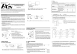
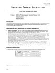
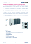
ISSUE 2
Installation Instructions for the
BZE6/V6 and BZG/H Enclosed Switches
MOUNTING
• E6 (side mount) and V6 (flange mount): #6
screws (#8 available on certain listings). E6
enclosures meet NEMA 1; V6 enclosures meet
NEMA 1 and 3*.
• BZG/H; #10 screws. Enclosures meet NEMA 1,
3*, 4*, 13*.
• Side and bottom mounting available. Side mount
from either side.
1. Mount switches on flat, rigid surface.
2. Sealed, side mounted: Use sealing washers
under screw heads on one side; between switch
and mounting surface on other side.
3. Unsealed, side mounted: Use lockwashers
under screw heads on one side; under nut on
other side.
4. Connect conduit to complete seal.
*Except Q plungers.
REPLACEMENT PARTS
Basic switch: order according to catalog listing on
basic switch being replaced. Replacement packet
includes basic switch, mounting hardware, seal
boot and bands where required.
PK 88173
WIRING
Connect grounding screw or lug.
Solderless connections:
1. Use only insulated connectors.
2. Position connectors to provide as much spacing
as possible.
NOTICE
1. Do not drill or machine housing.
2. Do not lubricate any internal part of switch.
3. Do not allow internal conduit condensation to
drain into switch.
4. Do not enlarge mounting holes.
CONDUIT SEALING PACKETS
Packet Listing
2PA6
Cable O.D. In. (mm)
.400 - .435 (10,2 - 11,1)
2PA16
2PA1
.435 - .470 (11,1 - 12,0)
.530 - .570 (13,5 - 14,5)
Actuators or Accessories
Part
N2 actuator (roller lever)
Q2 actuator (roller lever)
N28 actuator (one-way roller lever)
Q28 actuator (one-way roller lever)
Listing
6PA2
6PA1
6PA16
6PA41
N62 Actuators (rod lever)
6PA140-E6
Q62 Actuators (rod lever)
N4 Actuators (manual button)
Q4 Actuators (manual button)
6PA62
6PA9
6PA7
N18 Actuators (spring)
N18 Actuators (spring and bushing)
6PA195
6PA187-E6
Conduit Seal
2PA1
2PA6
2PA16
Seal Boot (black elastomer)
Seal Boot (orange silicon)
Bottom Cover E6
10PA2
10PA1
3PA13-E6
Bottom Cover V6
3PA14-V6
Pilot Light for BZG/H
15LT1
MICRO SWITCH Sensing and Control
LIQUID TIGHT CONDUIT FITTING
2PA17
.170 - .470 (4,3 - 12,0) 1/2 NPT
6PA187-E6 ACTUATOR PACKET
PK 88173
BZE6/V6 and BZG/H Enclosed Switches
N18 TYPES
If actuator or basic switch is replaced, the
actuator may need adjustment to duplicate original
switch operating point. To adjust operating point,
remove lower seal band from base of seal boot.
“Peel back” seal boot to expose bushing. With basic
switch unoperated, slowly turn bushing clockwise
until basic switch operates. Do not turn further
after operating click is heard. Turn bushing back
1/2 turn. Tighten jam nut on bushing.
ACTUATOR DESCRIPTION
“Q”: unsealed. “N”: seal boot around plunger.
Horizontal and vertical lever adjustment.
• N80 & Q8: Roller plunger actuated.
• N81 & Q81: Cross roller plungers
• N2 & Q2: Roller lever for slide or cam operation.
• N28 & Q28: one-way roller lever actuator.
• N62 & Q62: 6 inch rod actuator.
• N4 & Q4: large button for easy hand operation.
• N18: Coil spring wobble lever.
N2 & Q2, N4 & Q4, N28 & Q28, N62 & Q62 TYPE
ACTUATOR ADJUSTMENT
Vertical Adjustment
Vertical Adjustment Range
N2 & Q2 - Roller lever
N4 & Q4 - Hand op.
N62 & Q62 - Rod lever
N28 & Q28 - One way
225°
180°
225°
180°
To adjust: loosen
hex nut, adjust arm
to desired position,
tighten hexnut.
Calibration
1. One lever arm serration: 8.18°.
2. One serration of lever arm and fluted washer as a
unit: 8°.
3. One serration of lever arm with one serration of
fluted washer in opposite direction: 0.18°.
MICRO SWITCH
Honeywell Inc.
11 West Spring Street
Freeport, Illinois 61032
Printed with Soy Ink
on 50% Recycled Paper
PK 88173 ISSUE 2 496 Printed in USA
LUBRICATING INSTRUCTIONS for Roller
Plunger Switches only (N80, N81, Q8, Q9, Q81)
For maximum life, periodically put a drop or two
of lightweight oil on the roller. Specific application
conditions will determine lubricating frequency.
Horizontal Adjustment
Horizontal Adjustment Range
“Q” types; [8] 45° positions - loosen mounting
nut; adjust to new position, seating bracket base
pin. Tighten munting nut.
Sealed “N” types; loosen mounting nut; adjust
to any position; tighten mounting nut.
WARRANTY/REMEDY
Honeywell warrants goods of its manufacture as
being free of defective materials and faulty
workmanship. Commencing with date of shipment,
Honeywell’s warranty runs for 18 months. If
warranted goods are returned to Honeywell during
that period of coverage, Honeywell will repair or
replace without charge those items it finds
defective. The foregoing is Buyer’s sole remedy
and is in lieu of all other warranties, expressed
or implied, including those of merchantability
and fitness for a particular purpose.
For application assistance, current specifications,
pricing or name of the nearest Authorized
Distributor, contact a nearby sales office. Or call:
1-800-537-6945 USA
1-416-293-8111 Canada
1-815-235-6847 International
INTERNET
http://www.honeywell.sensing.com
[email protected]
Helping You Control Your World