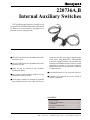
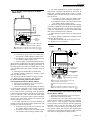
1
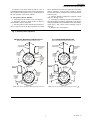
220736A,B
Internal Auxiliary Switches
220736A,B Internal Auxiliary Switch kits can
be installed in TRADELINE models of Modutrol
IV Motors to control auxiliary equipment as a
function of motor shaft position.
■ The 220736A includes one Spdt Micro Switch V3
precision switch.
■ The 220736B includes two Spdt Micro Switch V3
precision switches.
■ Either kit can be installed in any Tradeline
Modutrol IV Motor.
■ Kits provide switch mounting bracket for easy
installation internal to motor.
actuate the switches at any angle within the stroke
of the motor. Only Modutrol IV TRADELINE
models are equipped with the cam assemblies for
actuating field-addable auxiliary switches. Switch
adjustment procedures are the same as that for
switches that come factory installed in Modutrol
IV Motor models.
■ Switch differentials of 1° or 10° can be selected.
■ Leadwires color coded to ease correct wiring of
auxiliary equipment.
■ The auxiliary switches are actuated by adjustable
cams inside the motor. These cams can be set to
CONTENTS
Specifications ................................................ 2
Ordering Information .................................... 2
Installation .................................................... 2
Setting and Adjustments ................................ 6
Checkout ...................................................... 11
S.M. • Rev. 8-91 • ©Honeywell Inc. 1991 • Form Number 63-2228—2
220736A,B
SPECIFICATIONS • INSTALLATION • ORDERING INFORMATION
Specifications
MOUNTING: Switches factory-installed on bracket
designed for mounting inside motor.
WIRING: Color-coded, 15 in. [381 mm] leadwires.
MODELS: 220736A,B Internal Auxiliary Switches for
TRADELINE Modutrol IV Motors. Switches are actuated by cams in the motor. The cams can be set to
operate the switches at any point in the motor stroke.
220736A—Includes one Spdt Micro Switch V3
snap acting switch, mounted on left side and
operated by outer cam.
220736B—Includes two Spdt Micro Switch V3
snap acting switches.
SWITCH DIFFERENTIAL (difference between switch
make and break points): Approximately 1 or 10 degrees, determined by cam setting.
ELECTRICAL RATINGS:
One Contacta
120 V
240 V
Full Load
7.2
3.6
Locked Rotor
43.2
21.6
a
40 VA pilot duty, 120/240 Vac on opposite contact.
Installation
!
nal motor model number and refer to Tables 1-3.
2. From the appropriate table, determine switch
leadwire color coding and configuration (N.O. and N.C.
contacts).
3. For wiring convenience, make note of the difference
between the replaced motor and field addable switch color
coding.
4. Disconnect and remove the motor to be replaced.
5. Remove the cover from the wiring box of the
TRADELINE Modutrol IV motor.
6. Check motor for proper stroke setting. Adjust stroke
as needed. Refer to motor specification sheet.
7. Position the switch assembly above the motor as
shown in Fig. 1.
CAUTION
Disconnect power supply before beginning installation to prevent electrical shock or equipment damage.
NOTE: The wire colors of the 220736A,B auxiliary
switches are different from those of factory installed
auxiliary switches. See Tables 1-3 and Fig. 2.
1. When replacing a Modutrol motor determine origi-
Ordering Information
When purchasing replacement and modernization products from your TRADELINE wholesaler or your distributor, refer to the
TRADELINE catalog or price sheets for complete ordering number, or specify—
1. Order number.
If you have additional questions, need further information, or would like to comment on our products or services, please write or phone:
1. Your local Honeywell Residential and Building Controls Division Sales Office. (Check white pages of your phone
directory.)
2. Residential and Building Controls Division Customer Satisfaction
Honeywell Inc. 1885 Douglas Drive North
Minneapolis, Minnesota 55422-4386 (612) 542-7500
In Canada—Honeywell Limited/Honeywell Limitee, 740 Ellesmere Drive, Scarborough, Ontario M1P 2V9. International Sales and
Service Offices in all principal cities of the world.
International Sales Offices in all principal cities of the world. Manufacturing in Australia, Canada, Finland, France, Germany, Japan,
Mexico, Netherlands, Spain, Taiwan, United Kingdom, U.S.A.
2
220736A,B
INSTALLATION
8. Lower the switch assembly into place and tighten
the two mounting screws, making sure the switch followers are properly aligned with the inner and outer cams in
the motor. The 220736A includes only the switch for the
outer cam.
9. Run all switch leadwires through slots to line voltage section (at auxiliary end of motor), where connections
to auxiliary equipment should be made with solderless
connectors.
!
CAUTION
The auxiliary switches in the Series 91 low and
medium torque TRADELINE Modutrol IV Motors operate opposite to those in the Modutrol
motors listed in Tables 1 and 2, page 4. When
wiring the switches, connect the new switches to
the controlled equipment as shown in the appropriate table.
Fig. 1—Position of auxiliary switch(es) in motor.
MODUTROL IV WIRING BOX
VOLTAGE BARRIER
OUTER CAM
INTERNAL
AUXILIARY
SWITCH KIT
RIGHT
SWITCH
FOLLOWER
POWER
END
LEFT
SWITCH
FOLLOWER
INNER CAM
TRANSFORMER
(CAN BE FIELD - ADDED)
SLOTS (ROUTING SWITCH LEADWIRES
TO LINE VOLTAGE SECTION)
LINE VOLTAGE SECTION
M 455D
3
63-2228—2
220736A,B
INSTALLATION
TABLE 1—AUXILIARY SWITCH LEADWIRE COLORS FOR LOW AND MEDIUM TORQUE SERIES 91 MOTORS WITH
ONE AUXILIARY SWITCH.
Replace with
220736A,B
Leadwire
Factory-Installed Auxiliary Switch Leadwire Colora,b
Left
Auxiliary
Switch
N.O.
Yellow
W/Yellow
Orange
N.C.
Blue
W/Blue
Purple
Com.
Red
W/Red
Red
Right
Auxiliary
Switch
N.O.
B/Yellow
B/Yellow
B/Orange
N.C.
B/Blue
B/Yellow
B/Purple
Com.
B/Red
B/Red
B/Red
B/Red
Motor
M9171B1012
M734D1053
M7161B
M9171B1004
M9172W
M9164D1009
M9171B1020
M9164B
M7164B
M9174B1001
M9175W
M9174D1007
M9174B1019
M934A1565
M734J1072
M9174B1043
M975B1021
M9175D1014
M9174B1027
M934A1433
M934D1000
M975B1039
Motors with
M9174B1035
220736A,B
M934D1026
Auxiliary
M934D1059
Switch Kit
a
Wiring should be NEC Class 1 unless power supply meets Class 2 requirements. Tape unused leads. Make certain the current draw
of the external circuit is less than contact rating of switch.
b W/color= white wire with colored tracer.
B/color=black wire with colored tracer.
color = solid color wire.
TABLE 2—AUXILIARY SWITCH LEADWIRE COLORS FOR LOW AND MEDIUM TORQUE SERIES 91 MOTORS WITH
TWO AUXILIARY SWITCHES.
Replace with
220736A,B
Leadwire
Factory-Installed Auxiliary Switch Leadwire Colora,b
Left
Auxiliary
Switch
N.O.
Yellow
W/Blue
W/Yellow
W/Yellow
Orange
N.C.
Blue
W/Blue
Purple
Com.
Red
W/Red
W/Red
W/Red
Red
Right
Auxiliary
Switch
N.O.
B/Blue
B/Yellow
B/Yellow
B/Orange
N.C.
B/Yellow
B/Yellow
B/Blue
B/Purple
Com.
B/Red
B/Red
B/Red
B/Red
B/Red
Motor
M9171C
M9174C1009
M9161C
M9175Y
M9164D1009
M9174C1017
M9174C1033
M9164C
M975B1047
M9174D1007
M9174C1025
M934D1018
M9172C
M975B1062
M9175D1014
M9174C1041
M934A1243
Motors with
M934D1034
M934A1250
220736A,B
M934D1042
M934A1268
Auxiliary
M934A1276
Switch Kit
M934A1292
M934A1318
M965B1030
a
Wiring should be NEC Class 1 unless power supply meets Class 2 requirements. Tape unused leads. Make certain the current draw
of the external circuit is less than contact rating of switch.
b W/color= white wire with colored tracer.
B/color=black wire with colored tracer.
color = solid color wire.
4
220736A,B
INSTALLATION
TABLE 3—AUXILIARY SWITCH LEADWIRE COLORS FOR ALL MOTOR SERIES EXCEPT LOW AND
MEDIUM TORQUE SERIES 91 (See Tables 1 and 2 ).
Replace with
220736A,B
Leadwire
Factory-Installed Auxiliary Switch Leadwire Colora,b
Left
N.O.
Auxiliary N.C.
Switch
Com.
Blue
Yellow
Red
Blue
Yellow
Red
Right
N.O.
Auxiliary N.C.
Switch
Com.
Motor
W/Yellow
W/Blue
W/Red
B/Blue
B/Yellow
B/Red
M445A
M644E
M644L
M845A
M845E
M941C
M944B
M944C
M944G
M944H
M954C
M955C
M955E
M4182B
M4185B
M4185E
M4186H
M4186L
M6161B
M6184B
M6191B
M6194B
M6194E
M6282B
M6282E
M6284B
M6285B
M6294B
M8182B
M8185B
M9181B
M9184B
M9184E
M9185B
M9185E
M9194E
M9481E
M9484E
M644D
M744T
M744Y
M745T
M745Y
M941D
M944D
M944E
M944S
M945C
M945D
M954B
M954D
M955F
B/Yellow
B/Purple
B/Orange
B/Red
B/Red
M6181F
M6182F
M6184F
M6194F
M6281F
M6284C
M6284F
M6285C
M7281C
M7281Q
M7284C
M7284Q
M7285C
M7285Q
M9181C
M9182C
M9184C
M9184F
M9185C
M9481F
M9484F
M9182W
Purple
Orange
Red
M8175B
M865B
M6184D1035
M6194D1017
M6284D1000
M6285A1005
M6285A1013
M6294D1008
M8185D1006
M9184D1013
M9184D1021
M9185D1004
M9194D1003
Motors with
220736A,B
Auxiliary
Switch Kit
a Wiring should be NEC Class 1 unless power supply meets Class 2 requirements. Tape unused leads. Make certain the
current draw of the external circuit is less than contact rating of switch.
b W/color = white wire with colored tracer.
B/color = black wire with colored tracer.
color = solid color wire.
Fig. 2—Auxiliary Switch Wiring Diagram.
LEFT SWITCH
(OUTER CAM)
RIGHT SWITCH
(INNER CAM)
3
WIRING
Disconnect all power supplies to de-energize auxiliary
switch before servicing.
All wiring must comply with local codes and ordinances. Do not exceed switch ratings of auxiliary switches.
PURPLE
1
1
PURPLE/BLACK
RED
RED/BLACK
ORANGE
ORANGE/BLACK
2
5
1
Wiring should be NEC Class 1 unless power supply meets
Class 2 requirements. Tape unused leads. Make certain
the current draw of the external circuit is less than contact
rating of switch.
2
Switch leads on 220736A single-switch kit same as left
switch above.
3
Colors are tracers on black background.
M418C
63-2228—2
220736A,B
SETTINGS AND ADJUSTMENTS
Setting and Adjustments
AUXILIARY SWITCHES
The auxiliary switches are spdt switches that are actuated by adjustable cams. The cams are factory mounted on
the motor shaft at the power end of the motor. The settings
of the cams determine the point in motor shaft rotation at
which the auxiliary equipment will be switched on or off.
These cams can be set to actuate the switches at any angle
within the stroke of the motor. All TRADELINE motors
include auxiliary switch cams which permit installation of
this auxiliary switch kit (220736A, 220736B).
!
1. Live circuits are exposed during auxiliary
switch adjustment procedure. Always turn off
power before adjusting switch cams.
2. Do not turn motor shaft by hand or with
wrench as damage to the motor can result.
NOTE:The following instructions are for normally closed
motors (motor shaft rotates clockwise, as viewed from
the power end of the motor, on an increase in signal).
NOTE: When the slow-rise portion of the cam is used, the
switching differential is approximately 10° of rotation.
When the fast-rise portion of the cam is used, the switch
differential is approximately 1° of rotation. Do not use
the fast rise portion of the cam if fast cycling of
auxiliary equipment is undesirable.
Exact adjustment procedures vary for different
TRADELINE motor models. Find your model on the
following list. Then proceed to the correct section for that
model.
AUXILIARY SWITCH ADJUSTMENT
PROCEDURE
!
CAUTION
Motor Model
M8185
M9164, M9174, M9175
M9184, M9185, M9194
M6284, M6294
M6285
M6184, M6194
WARNING
FIRE OR EXPLOSION HAZARD
CAN CAUSE SEVERE INJURY OR DEATH
When auxiliary switches control combustion
equipment, incorrect wiring of the switches can
allow the burner to come on at high fire. Check
auxiliary switch wiring and cam adjustment before turning on the system. Watch the controlled
equipment through one complete cycle. Shut the
system down immediately if switches do not
correctly sequence the equipment .
Section
A
B
C
D
E
F
Additional instructions may also be found in the Auxiliary Switch Adjustment section in the specification sheet
included with the Modutrol IV Motor.
Review Table 4 and Fig. 3 before adjusting cams. Table
4 applies to both the left and right switches.
TABLE 4—AUXILIARY SWITCH POSITION WITH MOTOR SHAFT ROTATED TO EITHER SIDE OF
AUXILIARY SWITCH OPERATING POINT, AS VIEWED FROM POWER END.
Motor
Type
TRADELINE,
low and
medium
torque, series 91
All other
TRADELINE
motors
a
Cam
Arrangement
Red inner
cam, blue
outer cam
Blue inner
cam, red
outer cam
Switch
Differential
1°
Auxiliary Switch Contact Positions
N.O. Contacta
N.C. Contacta
(Red and Purple Leads)
(Red and Orange Leads)
Shaft
Shaft
Shaft
Shaft
Rotated
Rotated
Rotated
Rotated
ccw of
cw of
ccw of
cw of
Switch
Switch
Switch
Switch
Operating
Operating
Operating Operating
Point
Point
Point
Point
Closed
Open
Open
Closed
10°
Open
Closed
Closed
Open
1°
Open
Closed
Closed
Open
10°
Closed
Open
Open
Closed
cw = clockwise
ccw = counterclockwise
6
220736A,B
SETTINGS AND ADJUSTMENTS
To turn the cams, insert small screwdriver (1/8" or
3 mm blade) through wiring box into slot on cam and move
the screwdriver at the top. Refer to Fig. 3. Each division on
the cam represents 15° of motor rotation.
action. Each division on the cam represents 15° of motor
rotation. Therefore, if 60° of motor rotation is desired
before switch operates, rotate the cam 4 divisions from the
reference point.
4. Connect auxiliary equipment to auxiliary switch
leads. See Wiring section.
5. Turn on power and check for proper switch differential and switching of auxiliary equipment by driving the
motor through full stroke (in both directions). If necessary
repeat steps 3 and 5 until correct switching action is
obtained.
6. Replace cover of wiring box.
A) Two position motors (M8185):
1. Turn off power and remove cover of wiring box.
2. Determine amount of shaft rotation, in degrees,
desired before switch is energized.
3. Note the position of the cam slots and, with screwdriver, rotate the cam to the desired position for switch
Fig.. 3—Auxiliary switch adjustment.
ALL OTHER TRADELINE MOTORS
M9164D1009, M9174D1007 AND M9175D1014
MOVE SCREWDRIVER AT TOP ONLY TO ADJUST CAM.
MOVE SCREWDRIVER AT TOP ONLY TO ADJUST CAM.
1/8 IN. STRAIGHT-BLADE
SCREWDRIVER
SLOW RISE
PORTION
(APPROX.
10° DIFF.)
1/8 IN. STRAIGHT-BLADE
SCREWDRIVER
RIGHT/INNER
AUXILIARY
SWITCH
SWITCH
FOLLOWER
INNER
AUXILIARY
CAM
(RED)
SLOW RISE
PORTION
(APPROX.
10° DIFF.)
FAST RISE
PORTION
(APPROX.
1° DIFF.)
LEFT/OUTER
AUXILIARY
SWITCH
ONE
DIVISION
(15°)
LEFT/OUTER
AUXILIARY
SWITCH
SWITCH
FOLLOWER
OUTER
AUXILIARY
CAM
(BLUE)
FAST RISE
PORTION
(APPROX.
1° DIFF.)
SWITCH
FOLLOWER
INNER
AUXILIARY
CAM
(BLUE)
FAST RISE
PORTION
(APPROX.
1° DIFF.)
ONE
DIVISION
(15°)
SLOW RISE
PORTION
(APPROX.
10° DIFF.)
SWITCH
FOLLOWER
SLOW RISE
PORTION
(APPROX.
10° DIFF.)
OUTER
AUXILIARY
CAM
(RED)
FAST RISE
PORTION
(APPROX.
1° DIFF.)
MOTOR
CLOSE
MOTOR
OPEN
MOTOR
CLOSE
MOTOR
OPEN
RIGHT/INNER
AUXILIARY
SWITCH
POWER END
POWER END
NOTE: Cams shown separately to provide better view of inner cam.
NOTE: Cams shown separately to provide better view of inner cam.
M 875
7
63-2228—2
220736A,B
SETTINGS AND ADJUSTMENTS
Fig. 4—Auxiliary switch adjustment for low and
medium torque, Series 91 motors.
Fig. 5—Auxiliary switch adjustment for high
and extra high torque Series 91 motors.
2
2
L2
L2
1
L1
(HOT)
1
L1
(HOT)
Q209/S963 135-OHM
POTENTIOMETER
Q209/S963 135-OHM
POTENTIOMETER
W
W
B
B
R
R
T1
T2 R
B
T1
T2 R
B
W
STROKE ADJUST
CAMS (YELLOW)
STROKE ADJUST
CAM (BROWN)
RIGHT/INNER
AUXILIARY
SWITCH
RIGHT/INNER
AUXILIARY
SWITCH
LEFT/OUTER
AUXILIARY
SWITCH
W
LEFT/OUTER
AUXILIARY
SWITCH POWER END
OF MOTOR
INNER AUXILIARY CAM 3
OUTER AUXILIARY CAM 3
INNER AUXILIARY CAM (BLUE)
OUTER AUXILIARY CAM (RED)
1 Power supply. Provide disconnect means and
overload protection as required.
1 Power supply. Provide disconnect means and
overload protection as required.
2 Transformer may be external or internal.
2 Transformer may be external or internal.
M 852
3 Cam arrangement varies as shown in table.
INNER CAM
OUTER CAM
M9164D1009, M9164D1007,
M9175D1014
Red
Blue
ALL OTHER TRADELINE
MOTORS
Blue
Red
MOTOR MODEL
7. Check for proper switch differential and switching
of auxiliary equipment by driving the motor through full
stroke (in both directions) using the potentiometer. If
necessary repeat steps 5 and 7 for 1° differential, or 6 and
7 for 10° differential until correct switching action is
obtained.
8. Turn off power and disconnect potentiometer.
9. Connect auxiliary equipment to auxiliary switch
leads. See Wiring section.
10. Reconnect controller and power supply to motor.
11. Replace cover of wiring box. Turn on power.
M 851
B) Low and Medium Torque, Series 91 Modulating
(Proportional) Motors (M9164, M9174, M9175):
1. Turn off power and remove cover of wiring box.
2. Disconnect controller from motor.
3. Connect 135 ohm potentiometer to terminals R,W,
and B as shown in Fig. 4. Restore power.
4. Adjust potentiometer to drive motor to the position
where auxiliary equipment is to be switched.
5. For switch differential of 1°, check continuity of
auxiliary switch N.O. (Red to Purple) contacts and, with
screwdriver, rotate cam as follows:
a. If contacts are open, rotate cam counterclockwise
until N.O. (Red to Purple) contacts close.
b. If contacts are closed, rotate cam clockwise until
N.O. (Red to Purple) contacts open.
6. For switch differential of 10°, the cams must be
rotated with screwdriver approximately 180° prior to
setting switching action. Refer to Fig. 3. Check continuity
of the N.O. (Red to Purple) contacts and, with screwdriver,
rotate cam as follows:
a. If contacts are open, rotate cam clockwise until
N.O. (Red to Purple) contacts close.
b. If contacts are closed, rotate cam counterclockwise until N.O. (Red to Purple) contacts open.
C) High and Extra High Torque, Series 91 Modulating (Proportional) Motors (M9184, M9185, M9194):
1. Turn off power and remove cover of wiring box.
2. Disconnect controller from motor.
3. Connect 135 ohm potentiometer to terminals R,W,
and B as shown in Fig. 5. Restore power.
4. Adjust potentiometer to drive motor to the position
where auxiliary equipment is to be switched.
5. For switch differential of 1°, check continuity of
auxiliary switch N.O. (Red to Purple) contacts and, with
screwdriver, rotate cam as follows:
a. If contacts are open, rotate cam clockwise until
N.O. (Red to Purple) contacts close.
b. If contacts are closed, rotate cam counterclockwise until N.O. (Red to Purple) contacts open.
6. For switch differential of 10°, the cams must be
rotated with screwdriver approximately 180° prior to
setting switching action. Refer to Fig. 3. Check continuity
of the N.O. (Red to Purple) contacts and, with screwdriver,
rotate cam as follows:
8
220736A,B
SETTINGS AND ADJUSTMENTS
5. For switch differential of 10°, the cams must be
rotated with screwdriver approximately 180° prior to
setting the switching action. Refer to Fig. 3. Check
continuity of the N.O. (Red to Purple) contacts and rotate
cams as follows:
a. If contacts are open, rotate cam counterclockwise until N.O. (Red to Purple) contacts close.
b. If contacts are closed, rotate cam clockwise until
N.O. (Red to Purple) contacts open.
6. Check for proper switch differential and switching
of auxiliary equipment by driving the motor through full
stroke (in both directions). If necessary repeat steps
4 and 6 for 1° differential, or 5 and 6 for 10° differential
until correct switching action is obtained.
7. Disconnect power from switches or quick-connect
terminals.
8. Connect auxiliary equipment to auxiliary switch
leads. See Wiring section.
9. Reconnect controller and power supply to motor.
10. Replace cover of wiring box.
Fig. 6—Auxiliary switch adjustment for M6284,
M6294 motors
24 Vac
3
4
1
R 1
2 T
G
Y
STROKE ADJUST
CAMS (YELLOW)
RIGHT
AUXILIARY
SWITCH
LEFT
AUXILIARY
SWITCH POWER END
OF MOTOR
INNER AUXILIARY CAM (BLUE)
Fig. 7—Auxiliary switch adjustment for M6285
motors.
OUTER AUXILIARY CAM (RED)
1 Connect 24Vac to terminals 2 and 3 to drive motor open.
Connect 24Vac to terminals 3 and 1 to drive motor closed.
2
M 853
L2
1
L1
(HOT)
a. If contacts are open, rotate cam counterclockwise until N.O. (Red to Purple) contacts close.
b. If contacts are closed, rotate cam clockwise until
N.O. (Red to Purple) contacts open.
7. Check for proper switch differential and switching of auxiliary equipment by driving the motor through
full stroke (in both directions) using the potentiometer. If
necessary repeat steps 5 and 7 for 1° differential, or 6 and
7 for 10° differential until correct switching action is
obtained.
8. Turn off power and disconnect potentiometer.
9. Connect auxiliary equipment to auxiliary switch
leads. See Wiring section.
10. Reconnect controller and power supply to motor.
11. Replace cover of wiring box. Turn on power.
D) Series 62 Floating Control with Feedback
Non-Spring Return Motors (M6284, M6294):
1. Turn off power and remove cover of wiring box.
2. Disconnect controller from motor.
3. Connect 24 Vac power through switches or directly
to quick-connect terminals to drive motor to position
where auxiliary equipment is to be switched. Refer to
Fig. 6. Turn on power. Connecting power to terminals
2 and 3 will drive motor in the open direction, connecting
power to terminals 3 and 1 will drive the motor in the
closed direction. To stop the motor at desired position,
remove power from motor. Motor will remain at this
position until power is restored.
4. For switch differential of 1°, check continuity of
auxiliary switch N.O. (Red to Purple) contacts and, with
screwdriver, rotate cam as follows:
a. If contacts are open, rotate cam clockwise until
N.O. (Red to Purple) contacts close.
b. If contacts are closed, rotate cam counterclockwise until N.O. (Red to Purple) contacts open.
3
3
4
1
2
T
G
Y
STROKE ADJUST
CAM (BROWN)
RIGHT/INNER
AUXILIARY
SWITCH
LEFT/OUTER
AUXILIARY
SWITCH POWER END
OF MOTOR
INNER AUXILIARY CAM (BLUE)
OUTER AUXILIARY CAM (RED)
1 Power supply. Provide disconnect means and
overload protection as required.
2 Transformer may be external or internal mount.
3 Connect terminal 4 to terminal 2 to drive motor open.
Connect terminal 4 to terminal 1 to drive motor closed.
M 854
E) Series 62 Floating Control with Feedback Spring
Return Motors (M6285):
1. Turn off power and remove cover of wiring box.
2. Disconnect controller from motor.
3. Connect 24 Vac power and switches to drive motor
to position where auxiliary equipment is to be switched.
Refer to Fig. 7. Turn on power. Jumpering terminals
4 and 2 will drive motor in the open direction, jumpering
terminals 4 and 1 will drive the motor in the closed
direction. To stop the motor at desired position, disconnect jumpers. Motor will remain at this position until
connection is restored. Removing power at this point will
cause motor to spring return to closed position.
9
63-2228—2
220736A,B
SETTINGS AND ADJUSTMENTS
4. For switch differential of 1°, check continuity of
auxiliary switch N.O. (Red to Purple) contacts and, with
screwdriver, rotate cam as follows:
a. If contacts are open, rotate cam clockwise until
N.O. (Red to Purple) contacts close.
b. If contacts are closed, rotate cam counterclockwise until N.O. (Red to Purple) contacts open.
5. For switch differential of 10°, the cams must be
rotated with screwdriver approximately 180° prior to
setting the switching action. Refer to Fig. 3. Check
continuity of the N.O. (Red to Purple) contacts and, with
screwdriver, rotate cam as follows:
a. If contacts are open, rotate cam counterclockwise until N.O. (Red to Purple) contacts close.
b. If contacts are closed, rotate cam clockwise until
N.O. (Red to Purple) contacts open.
6. Check for proper switch differential and switching
of auxiliary equipment by driving the motor through full
stroke (in both directions). If necessary, repeat steps
4 and 6 for 1° differential, or 5 and 6 for 10° differential
until correct switching action is obtained.
7. Disconnect power from switches or quick-connect
terminals.
8. Connect auxiliary equipment to auxiliary switch
leads. See Wiring section.
9. Reconnect controller and power supply to motor.
10. Replace cover of wiring box.
Fig. 8—Auxiliary switch adjustment for M6184,
M6194 motors.
2
L2
1
L1
(HOT)
3
T1
T2 R W B
STROKE ADJUST
CAMS (YELLOW)
RIGHT/INNER
AUXILIARY
SWITCH
LEFT/OUTER
AUXILIARY
SWITCH POWER END
OF MOTOR
INNER AUXILIARY CAM (BLUE)
OUTER AUXILIARY CAM (RED)
1 Power supply. Provide disconnect means and
overload protection as required.
2 Transformer may be external or internal mounted.
3 Connect R-B to drive motor open. Connect R-W
to drive motor closed.
M 492B
F) Series 61 Floating Control Non-Spring Return
Motors (M6184, M6194):
1. Turn off power and remove cover of wiring box.
2. Disconnect controller from motor.
3. Connect 24 Vac power and switches to drive motor
to position where auxiliary equipment is to be switched.
Refer to Fig. 8. Turn on power. Jumpering terminals R and
B will drive motor in the open direction, jumpering
terminals R and W will drive the motor in the closed
direction. To stop the motor at desired position,
disconnect jumpers. Motor will remain at this position
until connection is restored.
4. For switch differential of 1°, check continuity of
auxiliary switch N.O. (Red to Purple) contacts and rotate
cams as follows:
a. If contacts are open, rotate cam clockwise until
N.O. (Red to Purple) contacts close.
b. If contacts are closed, rotate cam counterclockwise until N.O. (Red to Purple) contacts open.
5. For switch differential of 10°, the cams must be
rotated approximately 180° prior to setting the switching
action. Refer to Fig. 3. Check continuity of the N.O.
(Red to Purple) contacts and rotate cams as follows:
a. If contacts are open, rotate cam counterclockwise until N.O. (Red to Purple) contacts close.
b. If contacts are closed, rotate cam clockwise until
N.O. (Red to Purple) contacts open.
6. Check for proper switch differential and switching
of auxiliary equipment by driving the motor through full
stroke (in both directions). If necessary repeat steps
4 and 6 for 1° differential, or 5 and 6 for 10° differential
until correct switching action is obtained.
7. Disconnect 24 V power and switches.
8. Connect auxiliary equipment to auxiliary switch
leads. See Wiring section.
9. Reconnect controller and power supply to motor.
10. Replace cover of wiring box.
10
220736A,B
CHECKOUT
Checkout
!
Use the controller to run the motor fully open and then
fully closed. Make sure that the auxiliary equipment starts
and stops at the desired points in motor rotation. When
checkout is complete, return the controller to the desired
setting.
WARNING
FIRE OR EXPLOSION HAZARD
CAN CAUSE SEVERE INJURY OR DEATH
When auxiliary switches control combustion
equipment, incorrect wiring of the switches can
allow the burner to come on at high fire. Check
auxiliary switch wiring and cam adjustment before turning on the system. Watch the controlled
equipment through one complete cycle. Shut the
system down immediately if switches do not
correctly sequence the equipment.
11
63-2228—2
220736A,B
SETTINGS AND ADJUSTMENTS
Residential and
Building Controls Division
Honeywell Inc.
1985 Douglas Drive North
Golden Valley, Minnesota 55422
Residential and
Building Controls Division
Honeywell Limited—Honeywell Limitée
740 Ellesmere Road
Scarborough, Ontario
M1P 2V9
Helping You Control Your World
QUALITY IS KEY


![[Manual Makeup] - inverter & Plc](http://vs1.manualzilla.com/store/data/005906079_1-ccf407c70ed6dc9ae9bfcbd31676317c-150x150.png)