1
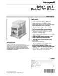
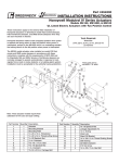
Honeywell
M9484 AND M9494 MODUTROL MOTORS ARE LOW
VOLTAGE, REVERSING PROPORTIONAL CONTROL
ACTUATORS FOR VALVES, DAMPERS AND AUXILIARY EQUIPMENT. THEY ARE ESPECIALLY DESIGNED FORCOMMERCIALOR INDUSTRIALOILOR
GAS BURNER CONTROL SYSTEMS.
•i Replace M941 motors.
0 Oil immersed motor and gear train for reliable performance and long life.
0
Wiring box provides NEMA 3 weather protection.
0 Actuator motor and circuitry operate from 24 volts
AC. Models available with factory installed transformer,
or internal transformer can be field added.
Cl Quick-connect terminals standard - screw terminal
adapter available.
Cl Adapter bracket for matching shaft height of older
motors is standard with replacement motors.
0 Field adjustable stroke (90” to 160’) models available.
q Nominal timing of 30 seconds for 90” and 60 seconds for 160” stroke is standard. Other timings are
available.
0 Die-cast magnesium housing.
,
q Available accessories include valve and damper
linkages, explosion proof housing, and auxiliary
switches.
0 Field addable interface modules can be mounted in
wiring box to upgrade actuator to Series 70 (electronic)
control.
•i
Models available with tapped output shaft.
0 M9481, M9484 rated for 150 lb.-in. torque at standard timings.
cl M9491, M9494 rated for 300 lb.-in. torque at 2 or 4
minute timings for 160“ stroke.
S.M.
Rev. 11-90
Form Number 63-2195-l
@Honeywell Inc. 1990
STANDARD MODELS
ELECTRICAL RATINGS:
control Type
T TTLix
94 is Series 90
~~
I
Power Rating
8 is high torque
150 lb.-in. at
standard timing
9 is high torque
300 lb.-in.at
2 or 4 min timing
VOLTAGE
Letter
D: is adjustable stroke
(90° to 1 60°)
No auxiliary switches
E: is adjustable stroke
(90° to 1 60°)
1 auxiliary switch
F: is adjustable stroke
(90° to 1 60°)
2 auxiliary switches
Output Drive
4 is dual-ended shaft,
non-spring return
1 is single-ended shaft,
non-spring return
POWER
CURRENT CONSUMPTfON (W)
DRAW (A)
Without
Transformer
24
0.8
18
With internal
Transformer
120
0.24
23
208
0.14
23
240
0.12
23
STROKE: Field adjustable from 90” to 160”. Start position
of shaft changes with adjustment of stroke. (Midpoint of
stroke remains fixed as stroke is adjusted, as shown in
Fig. 2.) Stroke is adjusted by means of cams located in
wiring compartment. (See Stroke Setting Procedure.)
Motors are shipped with stroke set at 90”.
DEAD WEIGHT LOAD ON SHAFT:
Power or Auxiliary End-200 lb. [90.8 kg] maximum.
Maximum Combined Load-300 lb. [136 kg].
AMBIENT TEMPERATURE RATINGS:
Maximum-150° F [66” C] @ 25% duty cycle.
Minimum-minus 40” F [-40° C].
CRANKSHAFT: 318 inch [9.5mm] square
M9484, M9494 have double-ended shaft.
M9481, M9491 have single-ended shaft.
NOTE: Some motors furnished to equipment manufacturers will have no adapter bracket, a single-ended shaft
and/or no wiring box.
CONTROLLER TYPE: Series 90 Control Circuit-135
ohm series 90 proportioning controller. Series 90 high
or low limit controller with manual minimum position potentiometer (with a combined total resistance of up to
500 ohms) may also be used in the control circuit.
MOTOR ROTATION: Normally closeda. The closed position is the limit of counterclockwise rotation as viewed
from the power end of the motor. See Fig 2. Motor opens
clockwise (as viewed from the power end). Motors are
shipped in the closed position.
aThe normal position is the position the motor will assume
with controller disconnected.
::::::::::::::::::::::::::::::::::::::::::::::::::::::::::::::::::::::::.........
_.. . . . . . . . . . . . . .:. . . . . . . . . . . . . . . . . . . . . . . . . . . . . . . . . . . . . . . . . . . . . . . . .. . . .. . .
~~~~~~~~:~~I~~~~CYJ~~~:R.~~~~~~~~~~~~~
t_~_._._._._._._._.‘. . . . . . . . . . . . . . . . . . . . . . . . . . . . . . . . . . . . . . . . . . . . . . . . . . . . . . . . . . . . .
.......L..-...................l..-...-....,-............ .......
.................................................................................................................
_..I........... . . . . . . . . . . . . . . . . _..... . . ..i _......
............. . . . . . . .
. . . . . . . . . . . . . ..i....
.......
. . ...
.......
:..
.....
...
.......
.............
:.:..
.:
...:
...
.....
:.:..
_._..
.......
:.:..
....,
.......
..,........................................................................................................
:.:.:
....................................._...............,.,.,.....,.,.,.,.,.,.,.,.,.,.,.,.,.,.,.,.,.,.,
. . . . ..i........... _..............‘.:.~~‘_~~::.~.
........... . .. . . . . . . . . . . . .
..i.......... . . . ..- ___._. ___:_~~r~_“:.~.~.~.~.~.~.~.~.~.~.~.~.~.~.~.~.~.~.~.~.~.~.~.~.~.~.:.:.:.:.:.:.:.:.:.:.:.:.:.:.:
.,.._...:.,.,.~_.:_:_._:_):_:_:.:.:.~.~.:.~.:.~.:.~.~.~.~.~.~.~.~.~.~.~.~.~.~.~.~.~.~.~.~.~.~.~.~.~.~.~.~.~.~.~.~.~~.~.~~.~.~~~~
WHEN PURCHASING REPLACEMENT AND MODERNIZATION PRODUCTS FROM YOUR AUTHORIZED
DISTRIBUTOR, REFER TO THE TRADELINE CATALOG OR PRICE SHEETS FOR COMPLETE ORDERING
NUMBER.
IF YOU HAVE ADDITIONAL QUESTIONS, NEED FURTHER INFORMATION, OR WOULD LIKE TO COMMENT
ON OUR PRODUCTS OR SERVICES, PLEASE WRITE OR PHONE:
1. YOUR LOCAL HONEYWELL RESIDENTIAL AND BUILDING CONTROLS SALES OFFICE (CHECK WHITE
PAGES OF PHONE DIRECTORY).
2. RESlDENTlAL AND BUILDING CONTROLS CUSTOMER SERVICE
HONEYWELL INC., 1885 DOUGLAS DRIVE NORTH
MINNEAPOLIS, MINNESOTA 55422-4386 (612)542-7500
(IN CANADA-HONEYWELL LIMITED/HONEYWELL LIMITEE, 740 ELLESMERE ROAD, SCARBOROUGH,
ONTARIO Ml P 2V9) INTERNATfONAL SALES AND SERVICE OFFICES IN ALL PRINCIPAL CITIES OF THE
WORLD.
2
AUXILIARY SWITCH RATINGS (amperes):
M94XXE has 1 spdt switch.
M94XXF has 2 spdt switches.
ONE CONTACT a
Full Load
Locked Rotor
120v
7.2
43.2
terfly valve. Requires adapter bracket packed with
motor.
Q209E,F Potentiometer-Limits minimum position of
motor.
Q68 Dual Control Potentiometer-Controls 1 through 9
additional motors.
Q181 Auxiliary Potentiometer-Controls 1 or 2 additional motors.
221455A Motor Crank Arm-Infinitely adjustable crank
arm. Approximately 0.75 inches shorter than the
4074ELY crank arm, can rotate through downward
position and clear base of motor without requiring
use of adapter bracket.
220741A Screw Terminal Adapter-converts the standard quick-connect terminals to screws terminals.
Transformers-mounted internally, provide 24 Vat
power to motor
198162JA-24 Vat; 50/60 Hz (for electrical isolation).
198162EA-120 Vat; 50160 Hz.
198162GA-220 Vat; 50160 Hz.
198162Al-120/208/240 Vat; 50160 Hz.
Q7130A-Interface Module with selectable voltage
ranges (4-7 Vdc, 6-9 Vdc, and 10.5-13.5 Vdc).
Adapts motor to M71 XX function.
Q7230A-Interface Module, selectable voltage or current control, with adjustable null and span. Adapts
motor to M72XX function; 4 to 20 mA or 2 to 10 Vdc.
Q7330A-Interface Module, for W936 economizer applications. Adapts motor to M73XX function.
Q7630A-Interface Module, 3-wire 14-17 Vdc control
with minimum position capability. Adapts motor to
M76XX function.
4074BYK-Control up to 6 M9lXX motors in unison
from one Series 90 controller.
4074EAU-Drive 2 or 3 M91 XX motors from a W973
Single-zone Logic Panel or W7100 Discharge Air
Controller.
4074EDC-Drive one M91XX motor from a 4-20 mA
Controller.
4074EED-Drive up to 4 M91 XX motors from a 4-20
mA Controller.
221508A Resistor Board-Plugs onto quick-connects
in wiring box of M9lXX motor. Can be used in place
of 4074BYK, EAU, EDC, or EED resistor kits (functions described above).
7616ADW Motor Crank Arm-Approximately 0.75
inches shorter than the 7616BR crank arm, can
rotate through the downward position and clear
base of motor without requiring use of adapter
bracket.
240v
3.6
21.6
a4O VA pilot duty, 1201240 Vat on opposite contact.
DIMENSIONS: See Fig. 1.
UNDERWRITERS LABORATORIES INC. LISTED
File No. E4436; Guide No. XAPX.
CANADIAN STANDARDS ASSOCIATION CERTIFIED:
General Listing File No. LR1620,400-E-)
‘U
STROKE STROKE RUNNING BREAKAWtY
15 set
30 set
75 18.51
150 [17.0]
30 set
1 min
150 [17.0]
300 [34.0]
1.2 min 1 2,4 minD 1 300 134.01 1 600 168.01
aBreakaway torque is the maximum torque available to
overcome occasional large loads such as a seized
damper or valve. MOTOR MUST NOT BE USED
CONTINUOUSLY AT THIS RATING.
bStalling of 2,4 min motor will damage motor.
ACCESSORIES:
ES6501 17 Explosion-proof Housing-Encloses motor
for use in explosive atmospheres. Not for use with
Q601, Q618, and Q455 Linkages. Order from Nelson Electric Co. Requires Honeywell 7617DM Coupling.
Q607 External Auxiliary Switch-Controls auxiliary
equipment as a function of motor position.
Q605 Damper Linkage-Connects motor to damper.
INCLUDES MOTOR CRANK ARM.
0618 Linkage-Connects Modutrol motor to water or
steam valve.
Q601 Bracket and Linkage Assembly-Connects
Modutrol motor to water or steam valve.
Ql OOA,B Linkage-Connects Modutrol motor to but-
WHEN INSTALLING THIS PRODUCT...
1. Read these instructions carefully. Failure to follow
them could damage the product or cause a hazardous
condition.
2. Checkthe ratings given in the instructions andon the
product to make sure the product is suitable for your
application.
3. Installer must be a trained, experienced service
technician.
4. After installation is complete, check out product
operation as provided in these instructions.
1. Disconnect power supply before beginning installation to prevent eiectrical shock and equipment damage.
2. Never turn the motor shaft by hand or with a
wrench-this will damage the motor.
3. Always conduct a thorough checkout when installation is complete.
1
3
63-2195-l
f--- 5.37 [136]
ADAPTER
BRACKET
FIG. 1-UIMtNSIUNS IN In.
NOTE: M9481, M9491 do not have auxiliary shaft. All other dimensions are the same.
LOCATION
install the Modutrol motor in any location except where
acid fumes or other deteriorating vapors might attack the
metal parts, or in atmospheres of escaping gas or the
explosive vaporsin excessive salt environments, mounting base and screws should be zincorcadmium plated, not
stainless steel or brass: Use the 220738A adapter bracket
for mounting on these surfaces.
Allow enough clearance for installing accessories and
servicing the motor when selecting a location. See Fig. 1.
If located outdoors, mount upright and use liquid-tight con-
duit connectors with wiring box to provide NEMA 3
weather protection.
MOUNTtNG
Always install motors with the crankshaft horizontal.
Mounting flanges extending from the bottom of the
motor housing are drilled for l/4 inch [6.4mm] machine
screws or bolts.
Motors are shipped from the factory in closed position
(at the limit of counterclockwise rotation as viewed from the
power end of the motor, as shown in Fig. 2) with the stroke
set at 90”.
4
NON SPRING RETURN MOTORS
ADAPTER BRACKET
The220738A Adaptor Bracket, positioned between the
motor and the equipment, raises the shaft height pttheM9484 motor by 0.75 inch to match that of the M941 motor.
This is required on all valve linkage applications, Q607
External Auxiliary Switch applications, and on some
damper linkage applications (either to provide clearance
for the crank arm to rotate through the downward position,
or to allow the damper linkage to reach the shaft).
To mount the motor with the bracket:
1. Mount the bracket to the equipment with existing or
standard bolts.
2. Mount the motor to the bracket using the bolts provided into the threaded holes of the bracket (see Fig. 3).
For valve linkage applications, the bracket should first
be mounted to the linkage (see Fig. 4). The bracket then
provides a convenient base on which the motor can be
positioned. After the motor shaft is aligned to the linkage,
it can then be attached to the bracket with the 4 bolts
provided. These bolts go through the inner set of holes in
the motor flanae and into the threaded holes of the bracket.
E373C
FIG. 2-LIMITS OF MOTOR ROTATION.
BOLTS
PROVIDED (4)
n
1
#12 OR l/4” ZINC PLATED MACHINE SCREWS OR BOLTS
M 3076
FIG. “MOUNTING MOTOR WITH 220738A ADAPTER BRACKET. The bracket is first mounted to the equipmel
with standard bolts. The motor is then mounted to the bracket using the bolts provided with the bracKet,
which thread into the threaded bracket holes.
linkage. In general, however, check the following points of
operation when installing a motor and linkage.
1. Linkages for valves and louver type dampers should
be adjusted so that the damper or valve moves through
only the maximum required distance when the motor
moves through its full stroke.
2. With modulating control, maximum damper opening
should be no more than 60”. Little additional airflow is
provided beyond this point.
3. The motor must be stopped at the end of its stroke
by the limit switch and must not be stalled by the damper
or valve. The motor will be damaged if it is not permitted to
complete its full stroke.
DAMPER LINKAGES
A 220738A Adapter Bracket is packed with replacement motors. Use of this bracket is optional for many
damper applications but may be needed in damper applications requiring the crank arm to rotate through the
bottom plane of the actuator. If the bracket is not used in a
replacement application, the damper linkage will have to
be adjusted to the new shaft position.
The motor comes without a crank arm. The crank arm
is included in the Q605 linkage or may be ordered separately (see Accessories).
For detailed instructions on the assembly of specific
linkages, refer to the instruction sheet packed with each
5
63-2195-l
Y BOLTS PROVIDED (4)
WIRING BOX
MOTOR
M 31%
MACHINE SCREWS OR BOLTS.
LTS SECURING BRACKET TO LINKAGE.
TIGHTEN AFTER SECURING MOTOR TO THE BRACKET USING FOUR BOLTS PROVIDED.
FIG. 4-MOTOR MOUNTING ON VALVE LINKAGE,.
4. Do not exceed the motor ratings in any installation.
VALVE LINKAGES
The 220738A Mounting Bracket must be used with the
Ql 00, Q601 and Q618 linkages in all valve applications.
Figs. 5 and 6 show internal schematics.
The motor terminals are quick-connects located on top
of theprintedcircuit boardshown in Fig.7.Ascrewterminal
adapter is standard on all Trade models and also may be
added to all models. Access to the wiring compartment is
gained byremovingthe4screws inthetoppf the wiring box
and lifting off the cover.
WIRING
Disconnect power supply before wiring to prevent electrical shock or equipment damage. All wiring must agree with
applicable codes, ordinances, and regulations.
A transformer is required to supply 24 Vat power to the
motor. Make sure that the power requirements stamped on
the motor correspond to the characteristics of the power
supply.
WIRING BOX
When used with liquid-tight conduit connectors, the wiring
box provides NEMA 3 weather protection for the motor.
The box also provides knockouts for wiring conduits and
encloses terminals. The wiring box, standard with replacement motors, is required for housing an internal transformer, internal auxiliary switches or Series 70 Interface
Modules.
5. Do not turn motor shaft manually or with a wrenchthis will damage the motor.
6
A
A
YELLOW LEAD
BLUE LEAD
1
I
CLOSE LIMIT
n
1
n
2
D IR ECTION
A
REDLEAD
2
‘n
WIRING SHOULD BE NEC CLASS 1 UNLESS POWER SUPPLY
MEETS CLASS 2 REQUIREMENTS. TAPE UNUSED LEADS. MAKE
CERTAIN THE CURRENT DRAW OF THE EXTERNAL CIRCUIT IS
LESS THAN CONTACT RATING OF SWITCH.
ON TWO-SWITCH MOTORS SECOND SWITCH HAS BLACK
LEADS WITH BLUE, YELLOW. AND RED TRACERS.
M 254
OF MOTOR TRAVEL AS VIEWED FROM POWE R E ND .
& CONNECT 24V POWER TO Tl-T2 TERMINALS ONLY. DO NOT CONNECT
POWER SUPPLY TO CONTROLLER TERMINALS. PROVIDE DISCONNECT
MEANS AND OVERLOAD PROTECTION AS REQUIRED.
3 TURN LIMIT POT FULL CLOCKWISE~FOR 160’
n
COUNTERCLOCKWISEr?FOR 90’ STROKE.
I
STROKE, FULL
FIG. 5-lNTERNAL WIRING OF An9494 MODUTROL
MOTORS.
MINIMUM
FIG. 6-AUXILIARY SWITCH INTERNAL WIRING.
STROKE ADJUSl
CAMS (YELLOW)
:zTloN
I
INNER AUXILIARY
INNER AUXILIARY
SWITCH CAM (BLUE)
OUTER AUXILIARY
SWITCH CAM (RED)
*
OUTER AUXILIARY
STROKE POT
NOTE: FEATURES AVAILABLE ON SOME MODELS ONLY.
M ml/\
FIG. 7-TERMINALS AND ADJUSTMENTS.
63-2195-l
AUXILIARY SWITCH CONNECTIONS
The M9484F has 2 internal auxiliary switches which
may be used to prove low fire and high fire positions.
1. To prove low fire use red (common) and yellow wires
connected to outer (left) switch. This switch makes red to
yellow and breaks red to blue as motor closes.
2. Wires connected to the inner (right) switch are black
with colored tracers. To prove high fire, use red tracer
(common) and blue tracer wires. The right switch makes
red tracer to blue tracer and breaks red tracer to yellow
tracer as motor opens.
Color coding and switching action are tabulated below
to aid the installer.
supplies to de-energize the
The M9484E has 1 internal auxiliary switch. The switch
wires are color-coded as follows: solid yellow-normally
closed (N.C.); solid red-common (COM.); solid
blue-normally open (N.O.).
SWITCH/CAM COLOR-CODING:
TABLE 1
SWITCH
LOCATlON’
CAM
ASSEMBLY
LOCATIONa
CAM
COLOR CODE
Left
Outer
Right
Inner
SWITCH WIRESb
COLOR
DESIGNATION
Red
Solid Yellow
Solid Red
Solid Blue
Normally Closed (N.C.)
Common (COM.)
Normally Open (N.O.)
Blue
Yellow Tracer
Red Tracer
Blue Tracer
Normally Closed (N.C.)
Common (COM.)
Normally Open (N.O.)
aViewed from power end of motor.
bSee Fig. 6.
SWITCHING ACTION:
TABLE 2
SWITCH
LOCATIONa
NORMAL
FUNCTION
MAKES
BREAKES
CAM
POSITIONb
MOTOR
POSITION
Left
Proves
Low Fire
Position
Red
to
Yellow
Red
to
Blue
High portion of cam
not in Contact
with Cam follower.
Closing
Right
Proves
High Fire
Position
Red Tracer
to
Blue Tracer
Red Tracer
to
Yellow Tracer
High portion of cam
in Contact
with Cam follower.
Opening
aViewed from power end of motor.
bSee Fig. 9
BEFORE SETTING STROKE:
1. Remove top cover from motor.
STROKE SEl-lING
On M94XXD,E,F motors, stroke is field adjustable and
can be set from 90” to 160”. Motors are shipped in 90”
position. In order to set stroke, both mechanical and electrical adjustments are required. The mechanical adjustments (cams) establish the full open (clockwise, n as
viewed from the power end) and full closed (counterclockwise 0 ) positions of the motor shaft. The electrical
adjustment (trim pot) provides sufficient total stroke angle
to ensure that cams will actuate both limit switches.
2. Disconnect controller from motor.
3. Connect R,B,W terminals on 135 ohm potentiometer (Q209 or S963) to matching terminals on motor.
SETTING 160” STROKE (Fig. 8):
1. Turn stroke pot fully clockwise f7 .
2. Drive motor to mid-position using 135 ohm pot
(Q209 or S963), or by jumpering B-R-W.
STROKE SETTING PROCEDURE
See Fig. 8.
3. Insert l/8 in. screwdriver blade into slot on inner
yellow cam and MOVE TOP OF SCREWDRIVER as far as
possible counterclockwise n (viewed from power
end). Repeat in successive cam slots until inner cam is
against counterclockwise 0 stop.
Detach linkage from motor before adjusting stroke.
8
MOVE SCREWDRIVER AT TOP
ONLY TO ADJUST CAM:
l/8 IN. STRAIGHT BLADE
SCREWDRIVER
OUTER STROKE
ADJUST CAMS
OUTER CAM
RY SWITCH CAMS
A1
POWER SUPPLY. PROVIDE DISCONNECT MEANS AND
OVERLOAD PROTECTION AS REQUIRED.
A2
TRANSFORMER MAY BE EXTERNAL OR INTERNAL.
NOTE: CAMS ARE OFFSET
PROVIDE BETTER VIEW OF BACK CAM.
M 3,3A
M305
FIG. 8-STROKE ADJUSTMENT SETUP.
l/8 IN. STRAIGHT-BLADE
SCREWDRIVER
STROKE ADJUST
CAMS (YELLOW)
RIGHT/INNER
INNER AUXILIARY CAM (BLUE)
OUTER AUXILIARY CAM (RED)
A 1
POWER SUPPLY. PROVIDE DISCONNECT MEANS AND
OVERLOAD PROTECTION AS REOUIRED.
A2
TRANSFORMER MAY BE EXTERNAL OR INTERNAL.
M 315c
OTOR CLOSE
POWER END
NOTE: CAMS ARE OFFSET VERTICALLY TO
PROVIDE BETTER VIEW OF BACK CAM.
M 3060
FIG. O-AUXILIARY SWITCH ADJUSTMENT SETUP.
9
63-2195-l
Switching action and color coding are shown in Tables
1 and 2 on page 8.
Motors with factory added auxiliary switches are
shipped in the closed position (counterclockwise fi ,
as viewed from power end) with auxiliary cams set to
actuate switches 30” from the closed position, and to
provide 1” differential. Wiih motor in closed (full counterclockwise r\ ) position, auxiliary switch breaks R-B.
IMPORTANT
Do not turn motor shaft by hand or with a wrench as
damage to the gear train and circuit board stroke
limit contacts will result.
IMPORTANT
Set cams by moving top of screwdriver only. Pressing screwdriver against sides of cam slots could
cause damage to motor end switches.
4. Insert l/8 in. screwdriver blade into slot on outer
yellow cam and MOVE TOP OF SCREWDRIVER as far as
possible clockwise n . Repeat in successive cam slots
until outer cam is against clockwise q stop.
NOTE: Excessive force will damage cam stop on hub.
5. Check motor stroke before connecting linkage.
6. Disconnect 135 ohm pot, reconnect controller, replace top cover on motor.
7. Attach linkage to motor.
AUXIUARY SWlTCH SElllNG PROCEDURE (Fig. 9)
1. Removetopcoverfrom motorto gain access to motor
terminals and cam adjustments.
2. Disconnect controller from motor and connect 135
ohm manual potentiometer with R-W-B terminals on pot
connected to corresponding terminals on motor (Fig. 9).
3. Adjust 135 ohm pot so that motor shaft turns to
position where auxiliary equipment is to be switched.
4. Insert a l/8 in., straight-blade screwdriver into slot on
cam associated with selected auxiliary switch. The inner
(blue) cam actuates the inner (right) switch, the outer (red)
cam actuates the outer (left) switch. MOVE TOP OF
SCREWDRIVER to set cams.
5. For switch differential of 1 O, check continuity of auxiliary switch R-B contacts and rotate cam as follows:
a. lf contacts are open, rotate cam clockwise n until
R-B contacts close.
b. lf contacts are closed, rotate cam counterclockwise
c until R-B contacts open.
6. For switch differential of loo, check continuity of
auxiliary switch R-B contacts and rotate cam as follows:
a. lf contacts are open, rotate cam counterclockwise
0 until R-B contacts close.
b. lf contacts are closed, rotate cam clockwise r\.
until R-B contacts open.
c. Final adjustment in the proper direction should be
made to obtain contact make or break at the desired
position.
7. Check for proper differential and switching of auxiliaryequipmentby runningmotorthroughfullstroke (inboth
directions), using 135 ohm pot. Repeat adjustment if
necessary.
8. Disconnect 135 ohm pot, reconnect controller, replace top cover on motor.
SETTING 90” STROKE (Fig. 8):
1. Turn stroke pot fully counterclockwise 0 .
2. Drive motor to mid-position, using 135 ohm pot
(Q209 or S963), or by jumpering B-R-W.
3. Insert l/8 in. screwdriver into slot on inner yellow
cam and MOVE TOP OF SCREWDRIVER as far as
possible clockwise q (viewed from power end). Repeat in successive cam slots until inner cam is against
clockwise stop.
NOTE: Excessive force will damage cam stop on hub.
4. Insert l/8 in. screwdriver blade into slot on outer
yellow cam and MOVE TOP OF SCREWDRIVER as far as
possible counterclockwise c . Repeat in successive
cam slots until outer cam is against counterclockwise stop.
NOTE: Excessive force will damage cam stop on hub.
5. Check motor stroke before connecting linkage.
6. Disconnect 135 ohm pot, reconnect controller, replace top cover on motor.
7. Attach linkage to motor.
AUXILIARY SWITCHES
The auxiliary switches in M9484E,F motors are actuated by adjustable cams. The cams are mounted on the
motor shaft at the power end of the motor. The settings of
the cams determine the point in motor shaft rotation at
which the auxiliary equipment will be switched on or off.
These cams can be set to actuate switches at any angle
within the stroke of the motor. Also each cam provides a
fast rise portion for switching (1 o differential) and a slow
rise portion for slow switching (10’ differential).
NOTE: If differential is changed from 1” to lo”, the switching action is reversed, thus: switch contacts R-B make
and R-W breakon acounterclockwise (closed) rotation.
CONNECTION DIAGRAMS (Figs. 10-13)
These motors are designed for use in series 90 proportioning control circuits employing a 135 ohm series 90
controller. Series 90 high or low limit controls or manual
minimum position potentiometers may also be used in the
control circuit.
The M9484 can also be used with some electronic
controllers which provide a 4-20 mA control output. lt is
necessary to use a resistor kii (4074EED for controlling up
to 6 motors) or Q7230 Interface Module to interface to the
4-20 mA source.
The standard series 90 controller has R, W, and B
terminals. As the controller reduces Rto W resistance, the
motor will drive closed (CCW as viewed from the power
end).
MODULATlNG SERIES 90 CIRCUIT
The potentiometers, one in the controller and one in the
motor, along with resistor network, form a bridge circuit. As
long as the value of the controlled medium remains at the
controller set point, the circuit is balanced, and the motor
does not run.
When the value of the controlled medium changes, the
potentiometer wiper in the controller is moved, which
unbalances the bridge circuit. This unbalance is amplified,
and energizes Triac switching to run the motor in the
direction necessary to correct the change in temperature
or pressure. The motor turns the feedback potentiometer
to rebalance the circuit and stop the motor.
10
SERIES 99
CONTROLLER
MOTOR
OPTIONAL CONNECTIONS
WITH 2-135 OHM POTENTIOMETERS IN SERIES.
SERIES 90
CONTROLLER
-
n
1
MOTOR
SERIES 90 HIGH
LIMIT CONTROL
POWER SUPPLY. PROVlDE DISCONNECT MEANS AND OVERLOAD
PROTECTION AS REQUIRED.
TRANSFORMER
2 TRANSFORMER MAY BE INTERNAL OR EXTERNAL TO MOTOR.
n
EJ74C
n
1
n
2
POWER SUPPLY. PROVIDE DISCONNECT MEANS AN,, OVERLOAD
PROTECTION AS REQUIRED.
TRANSFORMER MAY BE INTERNAL OR EXTERNALTO MOTOR.
E2rM4
IG. 1 l-MOTOR USED WITH ASERIESSO CONTROI
LER AND A SERIES 90 LOW OR HIGH LIMI
CONTROL.
SPDT SWITCH
OR SERIES 60
CONTROLLER
USED AS A
4.20 mA
SOURCE
SINGLE MOTOR
I
SLAVE
TRANSFORMER
MOTOR(S)
1 POWER SUPPLY. PROVIDE DISCONNECT MEANS AND OVERLOAD
1
PROTECTION AS REOUIRED.
2 USE SOLID LINE CONNECTION FOR POSITIVE CLOSING TO
!h
MINIMUM POSITON. SUBSTITUTE DOTTED LINE CONNECTION
FOR POSITIVE FULL CLOSURE.
UP TO 4 ADDITIONAL SLAVE MOTORS (6 TOTAL,
3 TRANSFORMER MAY BE INTERNAL OR EXTERNAL TO MOTOR.
!I
A RESISTOR (A) DEPENDS ON NUMBER OF SLAVES. SEE RESISTOR SELECTION CHART IN TEXT.
M428
2 SEE MOTOR SPECIFICATIONS FOR
n
ACTUAL TERMINAL ARRANGEMENT.
E474A
;.
L
12-CONNECTIONS FOR MOTOR, SERIES 90
CONTROLLER, MINIMUM POSITION POTENTIOMETER (ETC.).
FIG. 13-CONNECTlONS FOR MOTOR USED WITH 4
TO 20 mA CONTROL.
11
63-2195-I
4074EED RESISTOR SELECTION CHART FOR
4-20 mA
MIINIMUM
OUTPUT
VOLTAGE
REQUIRED
RESISTOR (A)
MOTORS (Vdc)b
(Ohms)
Part No.
1
1.7
237
80213QCDHA
2
2.0
150
802139BFAA
:
5
6
2.3 2.7
3.0
3.3
124 113
105a
97.6”
802139BCEA 802139BBDA
-
a Not part of this kit, obtain separately.
b These values represent the controller output voltage
required to drive the motors.
CHECKOUT
After installation and linkage adjustment, check the entire
motor and control hookup to ensure that* The motor operates the damper or valve properly.
The motor responds properly to the controller.
Inspect the motor, linkage, and valve or damper to see
that all mechanical connections are correct and secure. In
damper installations, the pushrod should not extend more
than a few inches past the ball joints. Check to see that
there is adequate clearance for the linkage to move
through its stroke without binding or striking other objects.
Check to see that cams operate the auxiliary switches,
if used, at the desired point of motor rotation.
l
NOTE: Motors are shipped in the fully closed position (the
limit of counterclockwise rotation as viewed from the
power end of the motor) with the stroke set at 90”.
SERIES 90 MOTORS OPERATION CHECK WITH MODUTROL MOTOR DISCONNECTED FROM CONTROLLER
STEP
1.
2.
3.
4.
5.
ACTION
Apply 24 Vaca.
Open terminal B and short W to R.
Open terminal W and short B to R.
Connect terminals R to B to W.
6.
7.
Remove jumpers from R, B, and W.
Check voltage between B and R,
and W and R.
Motor does not drive.
Voltage out of range.
8.
Disconnect 24 Vat.
RESPONSE
None.
Motor drives closed.
Motor drives open.
Motor must drive to Midposition.
17 to 20 Vdc.
Motor is defective.
Motor printed wiring board
is defective.
Spring return motors return
to their normal mechanical
position.
IF NO OR LIMITED RESPONSE
Proceed to Step 6.
Proceed to Step 6.
Proceed to Step 6.
No voltage or out of range. Proceed
to Step 7.
Replace motor.
Replace motor.
Spring mechanism defective
-replace motor.
NOTES:
a Ensure motor transformer is sized properly. If a common transformer is used to power multiple motors, ensure power
input is in phase with all motors.
b Motors may operate in Series 90 or two-position control applications. However, checking voltage between terminals
R to B and R to W is necessary to confirm proper operation in electronic (W973, 4 to 20 mA etc.) applications.
DAMPER APPLICATION
1. Turn off power and remove wiring from the old
actuator.
2. Remove crank arm from shaft of old actuator and
remove the old actuator.
3. Checkto see whether or not the mounting bracket is
needed. lf the linkage can reach the lowershaft position of
the new actuator and if the crank arm has clearance for the
needed rotation, then the bracket is not needed. Use
220738A Adapter Bracket or 221455A crank arm if crank
arm must rotate through the bottom plane of the motor (for
damper applications).
4a.If the bracket is not needed, mount the new actuator
directly to the equipment and refer to the INSTALLATION,
SETTlNGS&ADJUSTMENTS,andCHECKOUTsections
of these instructions as needed.
Honeywell Inc.
U.S.A.: 1885 Douglas Drive N.
Golden Valley, MN 55422-4386
CANADA: 740 Ellesmere Road
Scarborough, Ontario Ml P 2V9
4b.ffthe bracket is needed, referto the Adapter Bracket
sections and see Fig. 3 as well as the INSTALLATION,
SETTINGS &ADJUSTMENTS, and CHECKOUTsections
of these instructions.
5. Use old mounting bolts to mount the new actuator.
6. Mountthedampercrankarmandlinkagetotheshaft
of the new actuator.
8. Use the CHECKOUT procedures to test the proper
adjustment of the crank arm and linkage. .
VALVE APPLICATION
When installing a M9484, M9494 motor in a valve application which has a QlOO, Q601 or 0618 it will be
necessary to use the 220738A Adapter Bracket provided
to raisethe motorshafttothesame height asthatof theold
motor. Ensure motor stroke is 160” to operate Honeywell
V5011 two-way or V5013 three-way valves.
International Sates Offices in all principal cities of the world. Manufacturing in
Australia, Canada, Finland, Franc%, Germany, Japan, Mexico, Netherlands,
Spain, Taiwan, United Kingdom, U.S.A.
PRINTED IN U.S.A.
@
Lz3
QUALITY IS KEY