1
®
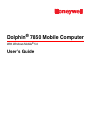
Dolphin
7850 Mobile Computer
With Windows Mobile® 5.0
User’s Guide
Disclaimer
Honeywell International Inc. (“Honeywell”) reserves the right to make changes in specifications and other
information contained in this document without prior notice, and the reader should in all cases consult
Honeywell to determine whether any such changes have been made. The information in this publication
does not represent a commitment on the part of Honeywell.
Honeywell shall not be liable for technical or editorial errors or omissions contained herein; nor for
incidental or consequential damages resulting from the furnishing, performance, or use of this material.
This document contains proprietary information that is protected by copyright. All rights are reserved. No
part of this document may be photocopied, reproduced, or translated into another language without the
prior written consent of Honeywell.
2006–2008 Honeywell International Inc. All rights reserved.
Web Address: www.honeywell.com/aidc
Trademarks
Dolphin, Dolphin RF, HomeBase, Mobile Base, and QuadCharger are trademarks or registered
trademarks of Hand Held Products, Inc. or Honeywell International Inc.
Microsoft, Windows, Windows Mobile, Windows CE, Windows NT, Windows 2000, Windows ME,
Windows XP, ActiveSync, Outlook, and the Windows logo are trademarks or registered trademarks of
Microsoft Corporation.
Other product names mentioned in this manual may be trademarks or registered trademarks of their
respective companies and are the property of their respective owners.
Patents
Please refer to the product packaging for a list of patents.
Other Trademarks
The Bluetooth trademarks are owned by Bluetooth SIG, Inc., U.S.A. and licensed to Honeywell
International Inc.
Table of Contents
Chapter 1 - Agency Information
Label Locations ....................................................................................................................1-1
Regulatory and Safety Approvals for all Dolphin Terminals ................................................1-2
FCC Compliance..................................................................................................................1-3
Chapter 2 - Getting Started
Out of the Box ......................................................................................................................2-1
Today Screen.......................................................................................................................2-2
Navigation Bar .....................................................................................................................2-2
Using the Stylus ...................................................................................................................2-3
Pop-Up Menus .....................................................................................................................2-3
Chapter 3 - Hardware Overview
Standard Terminal Configuration .........................................................................................3-1
Peripherals ...........................................................................................................................3-2
Accessories..........................................................................................................................3-3
Front Panel Features ...........................................................................................................3-4
Back Panel Features............................................................................................................3-5
Side Panel Features ............................................................................................................3-6
Battery Door Tether (Optional).......................................................................................3-7
I/O Connector.......................................................................................................................3-9
Rubber Bumpers ................................................................................................................3-10
Battery Power ....................................................................................................................3-11
Main Battery Pack ........................................................................................................3-11
Internal Backup Battery................................................................................................3-12
Resetting the Terminal .......................................................................................................3-15
Soft Reset (Warm Boot) ...............................................................................................3-15
Hard Reset (Cold Boot)................................................................................................3-15
Suspend Mode ...................................................................................................................3-15
Technical Specifications ....................................................................................................3-17
Chapter 4 - Using the Keyboards
Overview ..............................................................................................................................4-1
Using the Function Keys ......................................................................................................4-2
Using the Navigation Keys ...................................................................................................4-3
Using the Modifier Keys .......................................................................................................4-3
Keyboard Mode Indicator .....................................................................................................4-3
24-Key Keyboard .................................................................................................................4-4
Toggling Between Alpha and Numeric Modes ...............................................................4-4
24-Key Keyboard Numeric Key Combinations.....................................................................4-5
24-Key Keyboard Alpha Key Combinations .........................................................................4-6
38-Key Keyboard .................................................................................................................4-7
Toggling Between Numeric and Alpha Modes ...............................................................4-7
38-Key Keyboard Alpha Key Combinations .........................................................................4-8
38-Key Keyboard Numeric Key Combinations...................................................................4-10
Dolphin® 7850 Mobile Computer User’s
Guide
Rev C
4/30/2008
iii
Chapter 5 - Using the Imager Scanner Engine
Overview.............................................................................................................................. 5-1
Available Engines ................................................................................................................ 5-1
Available Laser Engines ...................................................................................................... 5-2
Supported Bar Code Symbologies ..................................................................................... 5-3
Activating the Engine........................................................................................................... 5-4
Decoding ............................................................................................................................. 5-5
Capturing Images ................................................................................................................ 5-7
Chapter 6 - System Settings
Overview.............................................................................................................................. 6-1
Personal Settings ................................................................................................................ 6-2
Buttons........................................................................................................................... 6-3
Menus - Modifying the Start Menu................................................................................. 6-5
System Settings................................................................................................................... 6-7
About ............................................................................................................................. 6-7
Backlight ........................................................................................................................ 6-8
Memory........................................................................................................................ 6-10
Power........................................................................................................................... 6-12
Remove Programs....................................................................................................... 6-14
Screen ......................................................................................................................... 6-15
Chapter 7 - Communication
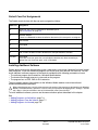
Communication Options ...................................................................................................... 7-1
Default Com Port Assignments ........................................................................................... 7-2
Installing Additional Software .............................................................................................. 7-2
Using ActiveSync................................................................................................................. 7-3
Adding Programs via ActiveSync................................................................................... 7-4
Connections Tab ................................................................................................................. 7-6
Connecting the Terminal to a Wireless Network ................................................................. 7-7
Connecting the Terminal to an ISP...................................................................................... 7-7
Adding Programs From the Internet .................................................................................... 7-7
Using Infrared Communication ............................................................................................ 7-8
Connections Manager ....................................................................................................... 7-10
Network Cards................................................................................................................... 7-12
Radio Manager .................................................................................................................. 7-13
USB to PC ......................................................................................................................... 7-15
Chapter 8 - Wireless PAN Communication with Bluetooth
Bluetooth Radio ................................................................................................................... 8-1
Enabling the Bluetooth Radio ........................................................................................ 8-1
BTExplorer........................................................................................................................... 8-1
Accessing BTExplorer ................................................................................................... 8-2
Using BTExplorer ................................................................................................................ 8-3
Connection Types................................................................................................................ 8-7
Device Types....................................................................................................................... 8-8
View Options ....................................................................................................................... 8-8
Menu Options ...................................................................................................................... 8-9
iv
Rev C
4/30/2008
Dolphin® 7850 Mobile Computer
User’s Guide
Discovered Devices........................................................................................................... 8-10
Refreshing Discovered Devices................................................................................... 8-10
Making the Terminal Discoverable .............................................................................. 8-10
Pairing ............................................................................................................................... 8-13
Chapter 9 - Dolphin HomeBase Device
Overview.............................................................................................................................. 9-1
Front Panel ......................................................................................................................... 9-2
Back Panel ......................................................................................................................... 9-3
Bottom Panel Dimensions ................................................................................................... 9-4
Powering the HomeBase Device......................................................................................... 9-5
Charging the Main Battery................................................................................................... 9-7
ActiveSync Communication................................................................................................. 9-8
RS-232 Cables .................................................................................................................... 9-9
Mounting the Dolphin HomeBase Device.......................................................................... 9-10
Chapter 10 - Dolphin QuadCharger Device
Overview............................................................................................................................ 10-1
Front Panel ....................................................................................................................... 10-2
Back Panel ........................................................................................................................ 10-3
Inserting and Removing Battery Packs ............................................................................. 10-3
Supplying Power to the QuadCharger Device................................................................... 10-3
Charging Batteries............................................................................................................. 10-4
Recommendations for Storing Batteries............................................................................ 10-4
Using the Battery Analyzer ................................................................................................ 10-5
Bottom Panel ..................................................................................................................... 10-6
Mounting the QuadCharger Device ................................................................................... 10-6
Troubleshooting................................................................................................................. 10-7
Chapter 11 - Dolphin ChargeBase
Overview............................................................................................................................ 11-1
Front Panel ....................................................................................................................... 11-2
Back Panel ........................................................................................................................ 11-3
Power Supply............................................................................................................... 11-3
Supplying Power to the ChargeBase................................................................................. 11-4
Inserting and Removing Terminals.................................................................................... 11-4
Charging Terminals in the ChargeBase ............................................................................ 11-5
Mounting the ChargeBase................................................................................................. 11-6
Chapter 12 - Cables Kits
Universal Cable Features .................................................................................................. 12-1
Using the Power Cable...................................................................................................... 12-2
Using the Mobile Charger.................................................................................................. 12-3
Using the Charge/Comm Cable......................................................................................... 12-4
Chapter 13 - Customer Support and Warranty
Technical Assistance......................................................................................................... 13-1
Product Service and Repair............................................................................................... 13-2
Dolphin® 7850 Mobile Computer User’s
Guide
Rev C
4/30/2008
v
Limited Warranty ............................................................................................................... 13-3
vi
Rev C
4/30/2008
Dolphin® 7850 Mobile Computer
User’s Guide
1
Agency Information
Label Locations
Dolphin 7850 mobile computers meet or exceed the requirements of all applicable standards
organizations for safe operation. However, as with any electrical equipment, the best way to ensure safe
operation is to operate them according to the agency guidelines that follow. Please read these guidelines
carefully before using your Dolphin mobile computer.
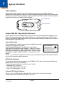
Laser Safety Label
Laser Safety Label
Dolphin 7850 802.11b/g (WLAN) & Bluetooth
Dolphin 7850 RF terminals are designed to comply with the most current applicable standards on safe
levels of RF energy developed by the Institute of Electrical and Electronics Engineers (IEEE) and the
American National Standards Institute (ANSI) and has been recommended for adoption by the Federal
Communications Commission (FCC).
Laser Safety Label
If the following label is attached to your product, it indicates the product
LASER LIGHT. DO NOT STARE INTO BEAM
contains a laser engine or laser aimer:
CLASS 2 LASER PRODUCT
1.0 mW MAX OUTPUT: 650nM
Laser Eye Safety Statement: This device has been tested in
IEC60825-1:1993+A1+A2
Complies with 21 CFR 1040.10 and 1040.1 1
accordance with and complies with EN60825-1: 1993+A1+A2 and 21
except for deviations pursuant to Laser
CFR 1040.10 and 1040.11, except for deviations pursuant to Laser
Notice No. 50, dated July 26, 2001.
Notice No. 50, dated July 26, 2001. LASER LIGHT, DO NOT STARE
INTO BEAM, CLASS 2 LASER PRODUCT, 1.0 mW MAX OUTPUT:
650nM.
Caution - use of controls or adjustments or performance of procedures other than those specified herein
may result in hazardous radiation exposure.
LED Safety Statement
This device has been tested in accordance with IEC60825-1 LED safety, and has been certified to be
under the limits of a Class 1 LED device.
The maximum power outputs for each diode are as follows:
• Illumination LED: 194.0 uW
• Aimer laser (5300 engine): 360.1 uW
• Aimer LED (5100 engine): 81.6 uW
Infrared LED Safety Statement
Caution - Class 1M LED radiation when open. Do not view directly with optical instruments.
The maximum power outputs for the IR LED is 145.1 uW.
Dolphin® 7850 Mobile Computer
User’s Guide
Rev C
4/30/2008
1-1
UL and cUL Statement
UL and cUL listed: UL60950-1 and CSA C22.2 No. 60950-1-03.
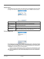
Regulatory and Safety Approvals for all Dolphin Terminals
Parameter
Specification
U.S.A.
Canada
European Community
FCC Part 15, Class B
ICES-003
EN 55022 (CISPR 22) Class B
EN60950:2000
EN60825-1:1994 + A11 + A2
EN55024:1998
The CE Mark on the product indicates that the system has been tested to and conforms with the
provisions noted within the 89/336/EEC Electromagnetic Compatibility Directive and the 73/23/
EEC and 93/68/EEC Low Voltage Directive.
For further information, please contact:
Hand Held Products BV, a wholly owned subsidiary of Honeywell International Inc.
Nijverheidsweg 9
5627 BT Eindhoven
The Netherlands
Honeywell shall not be liable for use of our product with equipment (i.e., power supplies, personal
computers, etc.) that is not CE marked and does not comply with the Low Voltage Directive.
1-2
Rev C
4/30/2008
Dolphin® 7850 Mobile Computer
User’s Guide
FCC Compliance
Dolphin terminals comply with part 15 of the FCC rules. Operation is subject to the following two
conditions: (1) this device may not cause harmful interference, and (2) this device must accept any
interference received, including interference that may cause undesired operation.
Dolphin RF Terminal—802.11b/g (WLAN) and/or Bluetooth
This device complies with Part 15 of the FCC Rules. Operation is subject to the following two conditions:
(1) this device may not cause harmful interference, and (2) this device must accept any interference
received, including interference that may cause undesired operation.
This equipment has been tested and found to comply with the limits for a Class B digital device pursuant
to Part 15 of the FCC Rules. These limits are designed to provide reasonable protection against harmful
interference in a residential installation. This equipment generates, uses, and can radiate radio frequency
energy and, if not installed and used in accordance with the instructions, may cause harmful interference
to radio communications. However, there is no guarantee that interference will not occur in a particular
installation. If this equipment does cause harmful interference to radio or television reception, which can
be determined by turning the equipment off and on, the user is encouraged to try to correct the
interference by one or more of the following measures:
• Reorient or relocate the receiving antenna.
• Increase the separation between the equipment and receiver.
• Connect the equipment into an outlet on a circuit different from that to which the receiver is connected.
• Consult the dealer or an experienced radio/TV technician for help.
If necessary, the user should consult the dealer or an experienced radio/television technician for
additional suggestions. The user may find the following booklet helpful: “Something About Interference.”
This is available at FCC local regional offices. Our company is not responsible for any radio or television
interference caused by unauthorized modifications of this equipment or the substitution or attachment of
connecting cables and equipment other than those specified by our company. The correction is the
responsibility of the user. Use only shielded data cables with this system.
In accordance with FCC 15.21, changes or modifications not expressly approved by Honeywell may void
the FCC authorization to operate the equipment.
CAUTION! Any changes or modifications not expressly approved by the grantee of this device could
void the user's authority to operate the equipment.
For body worn operation, this device has been tested and meets the FCC RF exposure guidelines when
used with the Honeywell Dolphin accessories supplied or designated for this product. Use of other
accessories may not ensure compliance with FCC RF exposure guidelines.
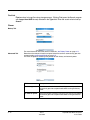
RF, Regulatory, and Safety Agency Approvals—802.11b/g (WLAN) and/or Bluetooth
Parameter
Specification
U.S.A.
Canada
FCC Part 15.247
RSS 210
Dolphin® 7850 Mobile Computer
User’s Guide
Rev C
4/30/2008
1-3
R&TTE Compliance Statement—802.11b/g (WLAN) and/or Bluetooth
Dolphin RF terminals are in conformity with all essential requirements of the R&TTE Directive (1999/5/
EC). This equipment has been assessed to the following standards as applicable:
Parameter
Specification
R&TTE
EN 300 328-2:2000
EN 301 489-1 (2002-08)
EN 301 489-17 (2002-08)
EN 60950:2000
EN 50361:2001
This product is marked with
in accordance with the Class II product requirements specified
in the R&TTE Directive, 1999/5/EC.
The equipment is intended for use throughout the European Community. PAN European Frequency
Range: 2.402—2.480 GHz.
Restrictions in France are as follows:
• Indoor use: Maximum power (EIRP*) of 100 mW for the entire 2.400—2.4835 GHz
• Outdoor use: Maximum power (EIRP*) of 100 mW for the 2.400—2.454 GHz band and maximum
power (EIRP*) of 10 mW for the 2.454—2.483 GHz band
Canadian Compliance
This Class B digital apparatus complies with Canadian ICES-003. Operation is subject to the following
two conditions: (1) this device may not cause harmful interference, and (2) this device must accept any
interference received, including interference that may cause undesired operation.
To prevent radio interference to the licensed service, this device is intended to be operated indoors and
away from windows to provide maximum shielding. Equipment (or its transmit antenna) installed outdoors
is subject to licensing.
Cet appareil numérique de la Classe B est conforme à la norme NMB-003 du Canada.
For European Community Users
Honeywell complies with Directive 2002/96/EC OF THE EUROPEAN PARLIAMENT AND OF THE
COUNCIL of 27 January 2003 on waste electrical and electronic equipment (WEEE).
Waste Electrical and Electronic Equipment Information
This product has required the extraction and use of natural resources for its production. It may contain
hazardous substances that could impact health and the environment, if not properly disposed.
In order to avoid the dissemination of those substances in our environment and to diminish the pressure
on the natural resources, we encourage you to use the appropriate take-back systems for product
disposal. Those systems will reuse or recycle most of the materials of the product you are disposing in a
sound way.
The crossed out wheeled bin symbol informs you that the product should not be disposed of along
with municipal waste and invites you to use the appropriate separate take-back systems for product
disposal.
If you need more information on the collection, reuse, and recycling systems, please contact your local or
regional waste administration.
1-4
Rev C
4/30/2008
Dolphin® 7850 Mobile Computer
User’s Guide
You may also contact your supplier for more information on the environmental performances of this
product.
Pacemakers, Hearing Aids and Other Electrically Powered Devices
Most manufacturers of medical devices adhere to the IEC 601-1-2 standard. This standard requires
devices to operate properly in an EM Field with a strength of 3V/m over a frequency range of 26 to
1000MHz. The maximum allowable field strength emitted by the Dolphin terminal is 0.3V/m according to
Subpart B of Part 1 of the FCC rules. Therefore, the Dolphin RF terminal has no effect on medical devices
that meet the IEC specification.
Microwaves
The radio in the Dolphin RF terminal operates on the same frequency band as a microwave oven.
Therefore, if you use a microwave within range of the Dolphin RF terminal you may notice performance
degradation in your wireless network. However, both your microwave and your wireless network will
continue to function. The Dolphin Batch terminal does not contain a radio, and therefore, is not affected
by microwave ovens.
Dolphin® 7850 Mobile Computer
User’s Guide
Rev C
4/30/2008
1-5
1-6
Rev C
4/30/2008
Dolphin® 7850 Mobile Computer
User’s Guide
2
Getting Started
Out of the Box
When you open the carton, please verify that the carton contains the following items:
• Dolphin 7850 mobile computer (the terminal)
• Main battery pack (7.4v, li-ion)
• Getting Started CD-ROM
• Dolphin 7850 Mobile Computer Quick Start Guide
Be sure to keep the original packaging in the event that the Dolphin terminal should need to be returned
for service. For details, see Limited Warranty on page 13-3.
If you ordered additional peripherals and accessories, verify that they are included with the order.
Step 1. Install the Main Battery Pack
Mechanical Switch
!
You must re-attach the battery door! This terminal contains a mechanical switch under the battery door that prevents
the terminal from initializing unless the battery door is closed.
Step 2. Charge the Batteries
There are two types of battery power: the main battery pack and the backup battery located inside the
terminal. The main battery pack powers the terminal and charges the internal backup battery.
Dolphin terminals ship with both batteries discharged of power. Charge the main battery pack for a
minimum of four(4) hours before initial use!
You can use one of the following charging peripherals:
• Dolphin HomeBase Device
• Dolphin QuadCharger Device
• AC Adapter Cable
Step 3. Boot the Terminal
The terminal begins booting as soon as power is applied and runs by itself. Do NOT press any keys or
interrupt the boot process.
When the boot process is complete, the Today screen appears and the terminal is ready for use.
Dolphin® 7850 Mobile Computer
User’s Guide
Rev C
4/30/2008
2-1
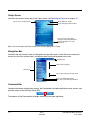
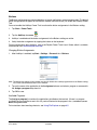
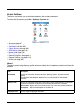
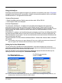
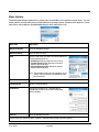
Today Screen
Initial boot and system resets end on the Today screen; see Resetting the Terminal on page 3-15.
Tap to access the Start menu
Tap to adjust the volume
Tap to change the date and time
These are icons of programs
running in the background. Tap to
open the program or access a
menu for it.
Note: You can also open the Today screen at any time by tapping Start > Today.
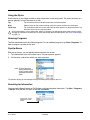
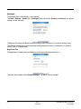
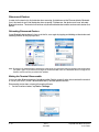
Navigation Bar
Located at the top of every screen, the Navigation bar provides access to the Start menu, shows the
current time (from the system clock), and displays both status and keyboard status icons.
Navigation bar
Tap to open a program
Start menu
Tap to open a program recently used
Tap to see additional programs
Tap to see to customize your terminal
Command Bar
Located at the bottom of application screens, the Command bar includes application menus, buttons, and
provides access to the Soft Input Panel (SIP).
The contents of the Command bar changes according to the open application.
2-2
Rev C
4/30/2008
Dolphin® 7850 Mobile Computer
User’s Guide
Using the Stylus
Use the stylus or your finger to select or enter information on the touch panel. The stylus functions as a
mouse; generally, a tap is the same as a click.
Tap
Tap the touch panel once to open menu items and select options.
Drag
Hold the stylus on the screen and drag across the screen to select text and images.
Tap & hold
Tap and hold the stylus on an item and a pop-up menu appears. On the pop-up menu, tap
the action of the task you want to perform.
!
Using sharp objects, such as paper clips, pencils, or ink pens can damage the touch panel and may cause
damage not covered by the warranty. For more information about the touch panel, see Touch Panel Display
on page 3-4.
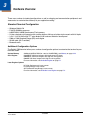
Selecting Programs
The Start menu does not fit all installed programs. To see additional programs, tap Start > Programs. To
open a program, tap once on the icon.
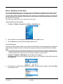
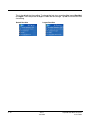
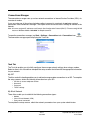
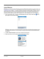
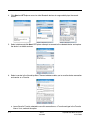
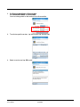
Pop-Up Menus
With pop-up menus, you can quickly choose an action for an item.
1. Tap and hold the stylus on the item name. The pop-up menu appears.
2.
Lift the stylus, and tap the action you want to perform.
Note: To close the menu
without performing an
action, tap the screen
anywhere outside the
menu.
The contents of pop-up menus depend change according to the program you’re in.
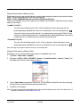
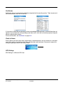
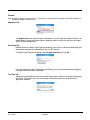
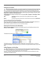
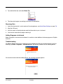
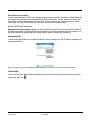
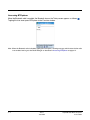
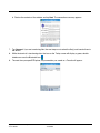
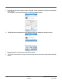
Searching for Information
You can use the Search feature or File Explorer to find and organize information. Tap Start > Programs
> Search. Enter the text you want to find and tap Search.
The Results section
displays the search
results.
Dolphin® 7850 Mobile Computer
User’s Guide
Rev C
4/30/2008
2-3
2-4
Rev C
4/30/2008
Dolphin® 7850 Mobile Computer
User’s Guide
3
Hardware Overview
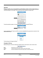
There are a number of standard configurations as well as charging and communication peripherals and
accessories to maximize the efficiency of your application setting.
Standard Terminal Configuration
•
•
•
•
•
•
•
•
Windows Mobile 5.0
PXA270 520MHz processor
64MB RAM X 64MB Synchronous Flash memory
24-key calculator-style numeric with scrolling alpha or 38-key calculator-style numeric with full alpha
3.5 in. 1/4 VGA 240 x 320 TFT color display with hard-coat industrial touch panel
5300 or 5100 Standard Range (SR) scan engine
WLAN radio (Wi-Fi certified)
Bluetooth radio
Additional Configuration Options
The Dolphin 7850 terminal offers you a number of configuration options to customize the terminal to your
business needs.
System Memory
Additional 64MB of RAM (for a total of 128MB RAM); see Memory on page 6-10.
Scan Engines
5100SR/SF VGA Area Imagers with bright green LED aimer
5300SR/SF VGA Area Imagers with High-Vis aiming pattern
5300HD VGA Area Imagers with High-Vis aiming pattern
For more information, see Available Engines on page 5-1.
Laser Engines Options
HP (High Performance) Laser scanner
LR (Long Range) Laser scanner
ALR (Advanced Long Range) Laser scanner
For more information, see Available Laser Engines on page 5-2.
Dolphin® 7850 Mobile Computer
User’s Guide
Rev C
4/30/2008
3-1
Peripherals
The following items are sold separately as part of a complete installation.
Dolphin HomeBase™ Device
This charging and communication cradle supports both RS-232 and USB communication, enabling your
terminal to interface with the majority of PC-based enterprise systems. When a terminal is seated in the
HomeBase device, its main battery pack charges in less than four(4) hours.
For more information, see Dolphin HomeBase Device on page 9-1.
Dolphin QuadCharger™ Device
This four(4)-slot charging station for Li-ion battery packs can charge each battery in less than four(4)
hours. The fourth slot features a battery analyzer that completely resets and re-calibrates a battery, then
displays remaining capacity.
For more information, see Dolphin QuadCharger Device on page 10-1.
Cables Kits
There are a number of cable kits that enable you to charge and communicate with other devices.
For more information, see Cables Kits on page 12-1.
Dolphin ChargeBase
This charging bay holds up to four(4) Dolphin 7850 terminals.
For more information, see Dolphin ChargeBase on page 11-1.
Mobile Mount
The Mobile Mount is a plastic cradle and RAM mount that holds and positions the terminal and can be
mounted on a fork truck, pallet lift, or other stable, stationary surface.
3-2
Rev C
4/30/2008
Dolphin® 7850 Mobile Computer
User’s Guide
Accessories
The following items are sold separately as part of a complete installation.
Battery Door Tether
For more information, see Battery Door Tether (Optional) on page 3-7.
Holster
The holster holds one terminal around the waist.
Li-ion Battery Pack
These are 7.4Vdc, 14.1 watt hour Li-on replacement battery packs; see Battery Power on page 3-11.
Protective Cover
The protective cover wraps around the terminal to protect it from wear and tear.
Protective Rubber Boot
The protective rubber boot wraps tightly around the terminal for added durability.
Screen Protectors
This is a pack of screen protectors that fit the touch panel display.
Stylus Three-Pack
This is a pack of three extra styluses.
Tote/Carry Bag
The tote and carry bag holds one terminal, a spare battery, and small printer. It can be shoulder-worn,
waist-worn, or carried by hand.
Wrist Lanyard/Stylus Tether
For more information, see Wrist Lanyard/Stylus Tether (Optional) on page 3-7.
Dolphin® 7850 Mobile Computer
User’s Guide
Rev C
4/30/2008
3-3
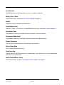
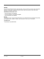
Front Panel Features
3.5 inch 1/4 VGA Touch
Panel Display
Decode LED
Scan LED
Keyboard Protection Ribs
Decode and Scan LEDs
The Scan LED lights red when you press the Scan trigger in scanning applications.
The Decode LED lights green when a scanned bar code is successfully decoded.
For more information, see LEDs on page 4-1.
Keyboard Protection Ribs
These ribs protect the keyboard and prevent keys from being pressed accidentally when the
terminal is placed facedown on a flat surface. For a complete overview of each keyboard, see
Using the Keyboards on page 4-1.
Touch Panel Display
The 3.5 inch 1/4 VGA (Video Graphic Array) display is a transflective color LCD (Liquid Crystal
Display) in TFT (Thin Film Transistor) color with a 240 x 320 resolution. The LCD is covered
by an industrial touch screen lens for maximum durability and backlit for maximum viewability;
see Backlight on page 6-8.
For touch panel input, use the stylus included with the terminal or your finger. The method you
choose depends on which one is most appropriate for your application. While there is a great
deal of variation in different applications, use of the supplied stylus provides greater touch
screen accuracy; see Using the Stylus on page 2-3.
Dolphin terminals ship with screen protectors already installed. Screen protectors help prevent
wear and damage to the touch panel; especially when used with applications that require highvolume interfacing with the touch panel. Screen protectors are subject to wear and tear.
Therefore, inspect screen protectors regularly and replace them when worn or punctured.
!
3-4
Using sharp objects, such as paper clips, pencils, or ink pens and may cause damage
not covered by the warranty.
Rev C
4/30/2008
Dolphin® 7850 Mobile Computer
User’s Guide
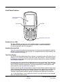
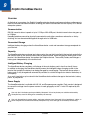
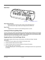
Back Panel Features
Battery Door
DC Power Jack
Tether Holes
Battery Door
The battery door covers and secures the main battery pack in the battery well. There is a
mechanical switch on the terminal under this door that puts the terminal in suspend mode (see
page 3-15) while the battery door is open. This door must be closed for the terminal to resume
operation. For more information, see Installing the Main Battery Pack on page 3-11.
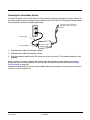
DC Power Jack
Located on the bottom of the pistol-grip handle, the 9.5V DC power jack receives external
power from the Dolphin Power Cable. When connected to the Power Cable, the terminal is
powered and the main battery pack is charging. For more information, see Using the Power
Cable on page 12-2.
Tether Holes
These holes are an attachment point for the Battery Door Tether (Optional) (see page 3-7).
Dolphin® 7850 Mobile Computer
User’s Guide
Rev C
4/30/2008
3-5
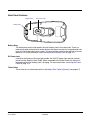
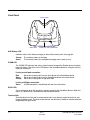
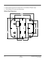
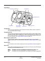
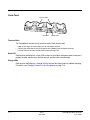
Side Panel Features
Beeper
IrDA Port
Angled Display
Scan Engine
Window
I/O Connector
I/O
Connector
Scan
Trigger
Integrated
Pistol-Grip
Stylus Loop
I/O
Connector
Stylus Slot
Tether/Lanyard Attachment Point
Note: This graphic shows the right side of the Dolphin 7850 terminal.
Angled Display
The touch panel display (see page 3-4) tilts up toward the user, which improves application
viewing when operating the terminal and reduces glare. Most important, the tilted display helps
you read decoded data without having to tilt your wrist.
Beeper
The beeper provides an audible indication of application events such as decoding (to indicate
a good or bad scan), touch panel touches, and keyboard input.
Scan Engine Window
The scan engine window provides an opening for the imager
scanner engines and points straight out of the device. Simply
point and scan.
Scan
Engine
Window
(with
engine)
There are several scan engine configurations available; see
Using the Imager Scanner Engine on page 5-1.
Integrated Pistol-Grip Handle
The pistol-grip handle is integrated into the terminal and is not removable, which makes the
unit more durable in the field. This handle is contoured so that the terminal is comfortable in
your hand and balanced during operations.
3-6
Rev C
4/30/2008
Dolphin® 7850 Mobile Computer
User’s Guide
IrDA Port
The infrared port is IrDA-enabled (Infrared Data Association) and communicates with other
IrDA-enabled devices such as PCs, printers, modems, or other Dolphin 7850 terminals. The
maximum data transfer speed is 115 Kbps with a duty cycle of 18.75%. For more information,
see Using Infrared Communication on page 7-8.
Scan Trigger
The front of the pistol-grip handle contains a scan trigger that activates the scan engine.
The scan trigger also wakes the terminal from Suspend Mode (see page 3-15).
Stylus Slot
Dolphin 7850 terminals ship with a stylus inserted into the pistol-grip handle. Stores the stylus
in this slot when you’re not using it. For more information about the stylus, see Using the Stylus
on page 2-3.
Tether/Lanyard Attachment Point
You can string optional hardware accessories through this hole to fasten hardware to the
terminal.
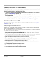
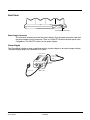
Wrist Lanyard/Stylus Tether (Optional)
The optional lanyard loops around your wrist and attaches the stylus to the terminal. One end loops
through the attachment point at the bottom of the handle and the other end loops around the hook at the
end of the stylus.
When the stylus is inserted into the stylus slot, you can insert your wrist for extra security while operating
the terminal. When the stylus is removed from the stylus slot, the stylus remains attached to the terminal
to prevent you from losing the stylus if you accidently drop it.
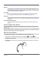
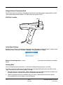
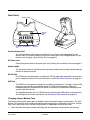
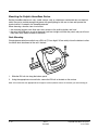
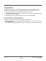
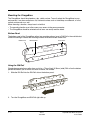
Battery Door Tether (Optional)
The optional battery door tether ensures that the battery door remains attached to the terminal even when
it is removed from the battery well. There are two pieces: the clip and the leather strap.
1.
Put the terminal in Suspend mode by pressing and holding Blue
2.
Disconnect the two pieces of the battery door tether; gently squeeze the outside of the clip and pull
the leather strap out of the clip.
3.
Take the leather strap and loop the lanyard portion through the attachment point on the handle as
shown below.
Dolphin® 7850 Mobile Computer
User’s Guide
Rev C
4/30/2008
+ Backlight
keys.
3-7
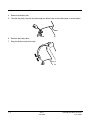
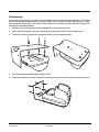
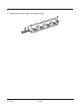
4.
Remove the battery door.
5.
Take the clip piece, loop the lanyard through the tether holes on the battery door as shown below.
6.
Reattach the battery door.
7.
Snap the leather strap into the clip.
3-8
Rev C
4/30/2008
Dolphin® 7850 Mobile Computer
User’s Guide
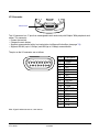
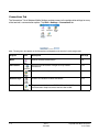
I/O Connector
I/O Connector
This I/O connector has 17 pins that are designed to work exclusively with Dolphin 7850 peripherals and
cables. This connector
• Powers the terminal.
• Charges the main battery.
• Supports communication with a host workstation via Microsoft ActiveSync (see page 7-3).
• Supports RS-232 (up to 115 Kbps) and USB (up to 12 Mbps) communication.
The pins on the I/O connector are as follows:
0IN$ESCRIPTION
53"
072
.#
.#
.#
.#
'.$
6/54
$42
53"
53"$%4
2)
$32
28$
243
48$
#43
Note: Signals referenced are for a DTE device.
Dolphin® 7850 Mobile Computer
User’s Guide
Rev C
4/30/2008
3-9
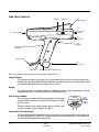
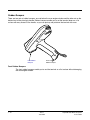
Rubber Bumpers
There are two sets of rubber bumpers: one set below the scan engine window and the other set on the
bottom front of the pistol-grip handle. Rubber bumpers enable you to set the terminal down on a flat
surface with easy access to the handle, so you can pick up and put down the terminal with ease.
Front Rubber
Bumpers
Pistol-Grip
Rubber Bumpers
Front Rubber Bumpers
The front rubber bumpers enable you to rest the terminal on a flat surface without damaging
the scan engine window.
3 - 10
Rev C
4/30/2008
Dolphin® 7850 Mobile Computer
User’s Guide
Battery Power
The intelligent battery technology built into the terminal features two types of battery power:
• The main battery pack installed under the battery door on the back panel.
• The backup battery located inside the terminal.
Both batteries work together to prevent data loss when the terminal is used over long periods of time.
Main Battery Pack
!
Use only the Li-ion battery packs provided by Honeywell. Use of any battery not sold/manufactured by
Honeywell may result in damage not covered by the warranty.
The 7.4V, 14.1 watt hour li-ion battery pack is the primary power source for the Dolphin terminal and the
internal backup battery. The li-ion battery is designed to operate in a temperature range of -10 to 50°C
(14 to 122°F).
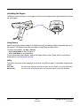
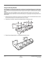
Installing the Main Battery Pack
Press Blue + Backlight keys to put the terminal
in Suspend Mode (see page 3-15) before
installing a new battery.
Mechanical Switch
The battery well area contains a mechanical
switch located under the battery door. When
the battery door is securely fastened, it
presses on the mechanical switch allowing
the terminal to power on and operate
normally.
When the battery door is removed, it no
longer presses on the mechanical switch,
which automatically suspends terminal
Mechanical Switch
operation. The terminal will not resume
normal operations again until the battery
door is re-fastened.
The mechanical switch works as described only when the terminal is running on battery power. If the
terminal is running on AC power (via Dolphin charging peripheral), the mechanical switch will not suspend
the terminal when the battery door is open.
If you open the battery door and remove the battery while the terminal is connected to AC power, the
terminal will continue operating. However, if you remove AC power while the battery door is open and the
battery is removed, the terminal will shut down without suspending and you will lose RAM data. To avoid
data loss when removing AC power, always either suspend the terminal or install the battery prior to
removing AC power.
Dolphin® 7850 Mobile Computer
User’s Guide
Rev C
4/30/2008
3 - 11
Charging Options
When the battery is installed in the terminal, you can insert the terminal into any one of the following
peripherals to charge the main battery pack:
• Dolphin HomeBase Device (see page 9-1)
• Dolphin ChargeBase (see page 11-1)
• One of the charging cables (see page 12-1)
To fully charge the li-ion battery outside the terminal, use one of the following:
• Dolphin QuadCharger Device (see page 10-1)
• Auxiliary Battery Well of the Dolphin HomeBase device
Charge Time
A completely discharged li-ion battery pack requires four(4) hours to charge to full capacity. Subsequent
charge times vary according to the charge level of the battery pack when charging begins.
The li-ion battery packs that ship with Dolphin terminals are completely discharged of power. Therefore,
charge the main battery pack for a minimum of four(4) hours prior to using the terminal on battery power.
Internal Backup Battery
Located inside the terminal, the backup battery is a 3.6V nickel metal hydride (NiMH) battery.
The internal backup battery prevents the terminal from being reset when you remove the main battery
pack. The backup battery retains RAM data and allows the real-time clock to remain operational for up to
30 minutes. If the terminal is left without the main battery pack for more than 30 minutes, the internal
backup battery discharges and needs to be recharged to function according to specifications.
Note: Even if the internal backup battery fails, data and programs stored in Flash memory are not totally lost, but
the terminal does automatically cold boot when you install a fully charged battery pack and you need to reset
the real-time clock.
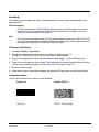
Charging
The internal backup battery charges off the main battery pack and requires eight(8) hours charge time to
backup RAM data for 30 minutes. You can begin using the Dolphin terminal after charging the main
battery for four(4) hours; however, the internal backup battery will continue to charge off the main battery.
To ensure that the internal backup battery functions properly, maintain a consistent power supply for the
first eight(8) hours of terminal operation. This power supply can be external power (using a charging
peripheral) or an installed, charged battery pack or a combination of both.
Guidelines
Follow these guidelines to maximize the life of the terminal’s internal backup battery:
• Keep a charged Li-ion battery pack in the terminal.
• Keep the Dolphin terminal connected to a power source when the terminal is not in use.
Managing Battery Power
Data and files saved on the Dolphin terminal may be stored in RAM memory; therefore, maintain a
continuous power supply to the terminal to help prevent data loss. When you remove a battery pack, insert
another charged battery pack in the Dolphin terminal. If the main battery pack is low, insert the terminal
into a charging peripheral to power the terminal and begin recharging the battery.
Note: If the main battery is low and the terminal is in suspend mode, pressing the SCAN trigger does not wake the
Dolphin terminal; you must replace the discharged battery with a fully charged battery.
3 - 12
Rev C
4/30/2008
Dolphin® 7850 Mobile Computer
User’s Guide
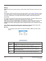
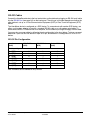
Default Critical and Low Battery Points
Dolphin terminals are programmed to display warnings when the battery reaches critical and low battery
points. The following registry entry sets both warning points:
[HKEY_LOCAL_MACHINE\System\CurrentControlSet\Control\Power]
There are two DWORD values in this registry entry: LowBatt and CriticalBatt. The default values for these
entries are as follows:
“LowBatt”=19 (25%)
This sets the Low Battery point to 25% (19 hex=25 decimal). When the battery hits the
percentage charge specified here, the user is notified by this icon in the Navigation bar
.
If the main battery is low and the terminal is in suspend mode, pressing the SCAN or Power
button won’t wake the Dolphin terminal; you must replace the discharged battery with a battery
charged over 25% mark before you can resume terminal operation.
“CriticalBatt”=a (10%)
This sets the Critical Battery point to 10% (a hex= 0 decimal). When the battery hits the
percentage charge specified here, the user is notified by this icon in the Navigation bar
.
Note: Warnings do not appear when the terminal is on external power.
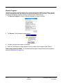
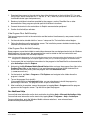
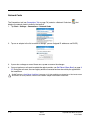
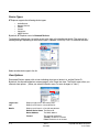
Setting Critical and Low Battery Points
Developers can re-reset the default battery points in the RegEdit Power Tool.
1. Tap Start > Power Tools > RegEdit.
2.
Drill-down to HKEY_LOCAL_MACHINE > System > CurrentControlSet > Control > Power. The
CriticalBatt and LowBatt values appear in the list.
3.
Tap the Value Name to change the Value Data. You can reset the Value Data from 0 (no warning)
to 99 (would warn whenever the charge drops below 99%).
4.
Tap OK to save changes.
Note: For more information about the RegEdit Power Tool, refer to the Dolphin Power Tools User’s Guide, which is
available for download at www.honeywell.com/aidc.
Dolphin® 7850 Mobile Computer
User’s Guide
Rev C
4/30/2008
3 - 13
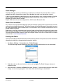
Checking Battery Power
Tap Start > Settings > System tab > Power.
For more information, see Power on page 6-12.
Storage Guidelines
To maintain optimal battery performance, follow these storage guidelines:
• Avoid storing batteries outside the specified range of -4° to 104° F (-20° to 40°C) or in extremely high
humidity.
• For prolonged storage, do not keep batteries stored in a charger that is connected to a power source.
Guidelines for Battery Pack Use and Disposal
The following are general guidelines for the safe use and disposal of batteries:
• Use only the Li-ion battery packs provided by Honeywell. Use of any battery not sold/manufactured by
Honeywell may pose a personal hazard to the user.
• Replace defective batteries immediately; using a defective battery could damage the Dolphin terminal.
• Never throw a used battery in the trash. It contains heavy metals and should be recycled according to
local guidelines.
• Don’t use a battery in any other manner outside its intended use in Dolphin terminals and peripherals.
• Don’t short-circuit a battery or throw it into a fire; it can explode and cause severe personal injury.
• Excessive discharge damages a battery. Recharge the battery when your terminal indicates low battery
power.
• If you observe that the battery is physically damaged in some way, please send it to Honeywell or an
authorized Honeywell service center for inspection.
• Although your battery can be recharged many times, it will eventually be depleted. Replace it after the
battery is unable to hold an adequate charge.
• If you are not sure the battery or charger is working properly, please send it to Honeywell or an
authorized Honeywell service center for inspection.
3 - 14
Rev C
4/30/2008
Dolphin® 7850 Mobile Computer
User’s Guide
Resetting the Terminal
There are two ways to reset the Dolphin terminal: a soft reset and a hard reset.
Soft Reset (Warm Boot)
A soft reset re-boots the device without losing RAM data. You would perform a soft reset 1) when the
terminal fails to respond, 2) after installing software applications that require a reboot, or 3) after making
changes to certain system settings.
1.
Press and hold the Red
+ ESC
keys for approximately five seconds. The screen turns white
and the decode and scan LEDs flash for approximately three seconds.
2.
When the reset is complete, the Today screen appears.
Hard Reset (Cold Boot)
!
A hard reset erases all of the data and applications stored in RAM memory and launches Autoinstall, which
re-initializes the terminal.
1.
Press and hold the Red
+ Tab
keys for approximately five seconds. The screen turns white
and the decode and scan LEDs light for approximately three seconds.
2.
The terminal re-initializes; see Boot the Terminal on page 2-1.
Note: Hard resets automatically launch a soft reset before ending on the Today screen.
Set the time and date after each hard reset to ensure that the system clock is real-time. Tap the date on
the Today screen to open the Clock and set the time and date.
Suspend Mode
Suspend mode suspends terminal operation. The terminal appears to be “off” when in suspend mode.
The terminal is programmed to go into suspend mode automatically when inactive for a specific period of
time. You can set this time period in the Power setting. For details, see the Advanced Tab section of the
Power (see page 6-12) setting.
To Put the Terminal in Suspend Mode
Press the Blue
+ Backlight
keys. You should put the terminal in suspend mode when you change
the battery pack; see Installing the Main Battery Pack on page 3-11.
To Resume Terminal Operation
To resume terminal operation (or “wake” the terminal),
• Press the Backlight key
.
• Press the Scan Trigger (see page 3-6).
Dolphin® 7850 Mobile Computer
User’s Guide
Rev C
4/30/2008
3 - 15
Troubleshooting
If the terminal does not wake when you press the scan trigger,
• The battery door may not be fully closed. The mechanical switch under the battery door prevents the
terminal from resuming operation until the door is closed.
• The main battery might be too low to resume operation. Remove the battery and install a fully charged
battery or connect the terminal to a Dolphin charging peripheral.
3 - 16
Rev C
4/30/2008
Dolphin® 7850 Mobile Computer
User’s Guide
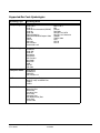
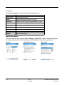
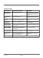
Technical Specifications
Feature
Description
Basic Features
Form Factor:
Purpose-built, compact, handle-style mobile computer
Operating System:
Windows Mobile 5.0
Development
Environment:
Hand Held Products Dolphin SDK for Visual Studio 2005–supports C/C++, C# and
Visual Basic development on Visual Studio 2005
Third Party Software:
SOTI MobiControl (remote device management), PowerNet™ Terminal Emulation
(TNVT, 3270, 5250), and ITScriptNet™
CPU:
Intel PXA 270 520 MHz
Memory:
64MB X 64MB & 128 MB RAM X 128 MB Flash memory options available
Display:
3.5 in. 1/4 VGA 240 X 320 TFT color display with hard-coat industrial touch panel
Imager/Scanner:
5100SR/SF VGA Area Imagers with bright green LED aimer
5300SR/SF VGA Area Imagers with High-Vis aiming pattern
5300HD VGA Area Imagers with High-Vis aiming pattern
HP (High Performance) Laser scanner
LR (Long Range) Laser scanner
ALR (Advanced Long Range) Laser scanner
Keyboards:
24-key calculator-style numeric with scrolling alpha
38-key calculator-style numeric with full alpha
Communications:
100K duty-cycle plugable/dockable RS232/USB connector, IrDA, Audio beeper
Power
Battery:
Main: Lithium-ion 7.4V, 14.1 watt hour, hot-swappable battery pack
Backup: Internal 3.6V nickel metal hydride (NiMH) battery saves RAM data for
30-minutes during main battery change
Run Time (estimated):
WLAN: 10+ hours at 1 scan/6 sec, 1 data package logged every scan, 802.11b/g
continuous connection, display backlight on full
Stand-by Time:
Device suspend mode: 8 days minimum
Charging:
9.5V AC input through handle charge port or USB/Serial connector, four(4) hours
recharge
Charging Peripherals:
AC wall adapter, Charge/Communication cable, single bay Home Base, 4 bay
Charge Base, battery QuadCharger
Wireless Radios
WLAN Standard:
Dolphin® 7850 Mobile Computer
User’s Guide
802.11b/g
Rev C
4/30/2008
3 - 17
Technical Specifications
Feature
Description
WLAN Security:
WEP, WPA Personal/Enterprise, WPA2 Personal/Enterprise, EAP-TLS, TTLS,
LEAP, PEAP, Cisco CCX compliant (pending)
WPAN (optional):
Bluetooth class 2, version 1.2 (optional feature)
Co-Located/
Operational:
Two radios: WLAN/WPAN
Physical
Operating Temperature:
Standard configuration: 14°–122°F / -10°–50°C nominal; -4° (-20°C) with
reduced runtime
Optional Bluetooth configuration: 32°–104°F / 0°–40°C
Construction:
• Magnesium alloy internal chassis with component shock mounts
• Engineering-grade polycarbonate outer housing
• Integrated rubber over-molded handle
Structural:
• 5 ft. (1.5m) multiple drops to concrete, all axis, across operating
temperature range
• Exceeds 2000 3 ft. (1m) tumbles
Environmental:
IP64 rated for blown dust/water intrusion
Dimensions:
Main housing: 7.1 in. Long X 3.3 in. Wide X 1.4 in. Deep
(18 cm Long X 8.4 cm Wide X 3.6 cm Deep)
Handle: 4.6 in. Long X 1.6 in. Wide X 1 in. Deep
(12 cm Long X 4.1 cm Wide x 2.5 cm Deep)
Weight:
Approximately 22 oz./684g
Warranty:
Standard: 2 years
3 - 18
Rev C
4/30/2008
Dolphin® 7850 Mobile Computer
User’s Guide
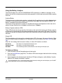
4
Using the Keyboards
Overview
The keyboard buttons are recessed under the overlay for maximum durability. The keyboard panel is
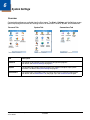
backlit for maximum viewability in various lighting conditions. There are two keyboard options:
24-Key Keyboard (see page 4-4)
38-Key Keyboard (see page 4-7)
VOL+
VOL+
DEL
DEL
INS
ESC
BKSP
ALPHA
F1
F2
7
\/_
8
F4
F5
4
F7
F8
1
2
TUV
PQRS
F10
– :
9
6
ALPH
F9
4
START
K
1
3
WXYZ
P
“
U
F1
0
+[ ]
.
*F2
V
B
8
G
5
L
2
Q
W
0
@
C
H
M
9
6
D
I
N
3
R
,
X#
F3
BKTAB
TAB
VOL
7
F
MNO
5
JKL
GHI
A
DEF
ABC
F6
START
=
F3
SP
-
SFT
BKTAB
TAB
VOL
PG
BKSP
SP
-
SFT
INS
ESC
PG
F4
S
Y
E
+
\
/
J
O
T
Z
F10
F9
F8
F7
F6
F5
Calculator Style Numbering
Both keyboards default to numeric mode and feature calculator-style numbering.
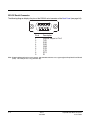
LEDs
The LEDs in the center of the keyboard work with the on-board imager scanner engine. Both LEDs are
user-programmable. Their default behavior is as follows:
Scan LED
The LED on the right lights red when you press the Scan trigger in scanning applications.
Decode LED
The LED on the left lights green when a scanned bar code is successfully decoded.
For more information, see Using the Imager Scanner Engine on page 5-1.
Color-Coding
Keyboard overlays are color-coded to indicate the functions performed or characters typed when the
color-coded key is pressed with the red or blue modifier key.
Key Types
In addition to the standard number and letter keys, both keyboards contain three types of keys:
1. Function Keys: Using the Function Keys (see page 4-2)
2.
Navigation Keys: Using the Navigation Keys (see page 4-3)
3.
Modifier Keys: Using the Modifier Keys (see page 4-3)
Dolphin® 7850 Mobile Computer
User’s Guide
Rev C
4/30/2008
4-1
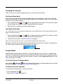
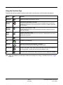
Using the Function Keys
Function keys perform specific functions and usually have the name of the function they perform.
Name
Key
Function
Backlight
Toggles the keyboard backlight on and off.
Backspace
(BKSP)
To backspace, press Red + left arrow.
Backspace moves the cursor back one space and deletes each time the key
combination is pressed. If you are typing text, a character is deleted each time
you backspace.
Backtab
(BKTAB)
To backtab, press the Blue + TAB.
Backtab moves the cursor back to the previous tab stop or field (on a form or
application window).
Delete
(DEL)
To delete, press Blue + ESC.
Deletes the next character forward. One character is deleted each time the key
combination is pressed.
Escape
Cancels an action.
OK
Functions as an Enter key.
Resume
Resume the terminal by pressing Blue + Backlight.
Note: You can also press the Scan trigger on the handle.
Space (SP)
To space, press Red + right arrow. Space moves the cursor one space forward. If
you are typing text, it moves the text one space forward as well.
Tab
Moves the cursor to the next tab stop or field (on a form or application window).
Note: There is no SCAN key on the Dolphin 7850 terminal keyboard; scanning is initiated with the Scan Trigger
(page 3-6).
4-2
Rev C
4/30/2008
Dolphin® 7850 Mobile Computer
User’s Guide
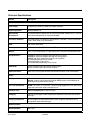
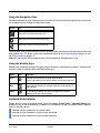
Using the Navigation Keys
Located in the center of each keyboard for easy access with either hand, the navigation keys enable you
to navigate the cursor through an application screen.
Press
To …
Move the cursor up one row or line.
Move the cursor down one row or line.
Move the cursor one character to the right.
Move the cursor one character to the left.
The navigation keys perform additional system functions when pressed in combination with the Blue and
Red modifier keys. For details, see the key combination tables for the 24-Key Keyboard (page 4-4) and
the 38-Key Keyboard (page 4-7).
Additional functionality of the navigation keys varies according to the application in use.
Using the Modifier Keys
Modifier keys modify the next key pressed to perform functions or type special characters. The keyboards
are color-coded to match the Blue and Red modifier keys.
Name
Key
Function
Shift
Provides shift functionality for application windows.
Tap once to modify the next letter pressed. Tap twice for caps lock.
Blue &
Red
Modifies the next key pressed. The overlay of each keyboard is
color-coded to indicate the character typed or function performed
with both keys.
Alpha
On the 38-key keyboard, the Alpha key toggles the keyboard
between alpha and numeric modes.
Keyboard Mode Indicator
Dolphin terminals have a Keyboard Status Power Tool (Start > Power Tools > Keyboard Status) that
displays an icon in the Navigation bar to indicate if the keyboard is in alpha or number mode. Keyboard
Status is active by default.
Indicates that the keyboard is in numeric mode.
Indicates that the keyboard is in alpha mode, uppercase.
Indicates that the keyboard is in alpha mode, lowercase.
Dolphin® 7850 Mobile Computer
User’s Guide
Rev C
4/30/2008
4-3
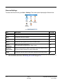
24-Key Keyboard
Navigation keys
Escape Shift LED
LED
key key
OK
key
Tab
key
VOL+
DEL
INS
ESC
PG
BKSP
-
SFT
Alpha Lock
F1
7
\/_
4
F5
START
F7
1
F8
TUV
PQRS
=
2
F10
– :
6
MNO
5
JKL
9
DEF
ABC
GHI
Power
F3
8
F6
F4
Backlight key
F2
BKTAB
TAB
VOL
ALPHA
Modifier
keys
SP
F9
3
WXYZ
“
0
+[ ]
Toggling Between Alpha and Numeric Modes
The 24-key keyboard defaults to numeric mode. Numeric mode is when you type numbers with the
number keys.
• Double-tap the Blue modifier key to toggle between alpha and numeric modes.
• Single-tap the Blue modifier key to toggle to alpha or numeric mode only for the next key pressed. The
keyboard returns to the previous state before the next key pressed.
• Press and hold the Blue modifier key to toggle to alpha or numeric mode for all keys pressed until the
Blue modifier key is released.
Alpha Mode
Alpha mode is when you type the letters or characters indicated in blue on the number keys.
Please note that when typing in alpha mode, you must use the same multi-press method you would use
when typing letters on a phone keypad. Each key press types the next letter in the sequence as displayed
by the alpha indicator.
You can still use the Blue modifier key for regular Blue key combinations in alpha mode; just press the
Blue modifier key and the next key. For combinations, see 38-Key Keyboard on page 4-7.
Shift Functionality in Alpha Mode
The SFT key performs all the normal windows shift key functions alpha mode, including capitalizing one
letter. On the 24-key keyboard, the SFT key also toggles caps lock on and off.
• Single-tap the SFT key to modify the next key pressed; if this is a letter, that letter is capitalized.
• Double-tap the SFT key to toggle caps lock on and off in alpha mode.
Note: Check the mode indicator (see Keyboard Mode Indicator on page 4-3) in the Navigation bar to see what mode
the keyboard is in.
4-4
Rev C
4/30/2008
Dolphin® 7850 Mobile Computer
User’s Guide
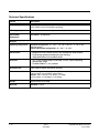
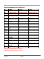
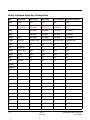
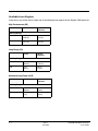
24-Key Keyboard Numeric Key Combinations
Key
Blue Mode
Num Mode
Num Shift
ESC
Delete
ESC
ESC
SFT
*Toggle Upper/Lower/Shift
*Toggle Upper/Lower/Shift
*Toggle Upper/Lower/Shift
Blue
***Toggle Num/Alpha
Blue Mode
***Toggle Num/Alpha
Red
Red Mode; see 24-Key Keyboard Alpha Key Combinations on page 4-6.
Asterisk
Start menu
*
*
Light
Suspend
Keyboard Light
Keyboard Light
Left
Left
Left
Up
Volume up
Up
Up
Down
Volume down
Down
Down
Right
Insert
Right
Right
OK
OK
OK
OK
Tab
Backtab
Tab
Tab
Period
- ; :
.
>
Comma
@ ? !
,
<
0
+ [ ]
0
)
1
pqrs or PQRS
1
!
2
tuv or TUV
2
@
3
wxyz or WXYZ
3
#
4
ghi or GHI
4
$
5
jkl or JKL
5
%
6
mno or MNO
6
^
7
/ \ _
7
&
8
abc or ABC
8
*
9
def or DEF
9
(
*Toggles uppercase and lowercase only on a double-tap.
**Single-tap SFT changes the mode for only the next character. Double-tap SFT key to change mode for all keys
pressed after.
***Toggles numeric and alpha modes only on a double-tap.
Dolphin® 7850 Mobile Computer
User’s Guide
Rev C
4/30/2008
4-5
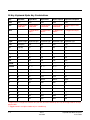
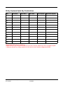
24-Key Keyboard Alpha Key Combinations
Key
Red Mode
Alpha Base
Alpha Shift
Alpha Caplock
Alpha Shift Caplock
ESC
ESC
ESC
ESC
ESC
ESC
SFT
*Toggle Upper/
Lower/Shift
*Toggle Upper/
Lower/Shift
*Toggle Upper/
Lower/Shift
*Toggle Upper/
Lower/Shift
*Toggle Upper/Lower/
Shift
Blue
***Toggle Num/
Alpha
***Toggle Num/
Alpha
***Toggle Num/
Alpha
***Toggle Num/Alpha
Red
Red Mode
Red Mode
Red Mode
Red Mode
Asterisk
#
*
*
*
*
Light
Keyboard Light
Keyboard Light
Keyboard Light
Keyboard Light
Keyboard Light
Left
Backspace
Left
Left
Left
Left
Up
Page Up
Up
Up
Up
Up
Down
Page Down
Down
Down
Down
Down
Right
Space
Right
Right
Right
Right
OK
OK
OK
OK
OK
OK
Tab
Tab
Tab
Tab
Tab
Period
=
- ; :
- ; :
- ; :
- ; :
Comma
“
@ ? !
@ ? !
@ ? !
@ ? !
0
F10
+ [ ]
+ { }
+ [ ]
+ { }
1
F7
pqrs
PQRS
PQRS
pqrs
2
F8
tuv
TUV
TUV
tuv
3
F9
wxyz
WXYZ
WXYZ
wxyz
4
F4
ghi
GHI
GHI
ghi
5
F5
jkl
JKL
JKL
jkl
6
F6
mno
MNO
MNO
mno
7
F1
/ \ _
{ } _
/ \ _
{ } _
8
F2
abc
ABC
ABC
abc
9
F3
def
DEF
DEF
def
*Toggles uppercase and lowercase only on a double-tap.
**Single-tap SFT changes the mode for only the next character. Double-tap SFT key to change mode for all keys
pressed after.
***Toggles numeric and alpha modes only on a double-tap.
4-6
Rev C
4/30/2008
Dolphin® 7850 Mobile Computer
User’s Guide
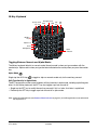
38-Key Keyboard
Navigation keys
Escape Shift LED
LED
key key
OK
key
Tab
key
VOL+
DEL
INS
ESC
PG
BKSP
-
SFT
Modifier
keys
7
F
4
ALPH
K
1
Power
Backlight key
P
U
F1
B
G
L
.
Q
*F2
W
V
8
5
2
0
@
F3
C
H
M
BKTAB
TAB
VOL
A
START
Alpha Lock
SP
9
6
D
I
N
3
R
,
X#
F4
S
Y
E
+
\
/
J
O
T
Z
F10
F9
F8
F7
F6
Alpha
indicators
F5
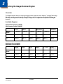
Toggling Between Numeric and Alpha Modes
The 38-key keyboard defaults to numeric mode. Numeric mode is when you type numbers with the
number keys. Alpha mode is when you type the letter indicated on the overlay when you press the number
key.
Alpha Mode
Single-tap the ALPH key
to toggle to alpha or numeric mode only for the next key pressed.
Shift Functionality in Alpha Mode
The SFT key performs all the normal windows shift key functions in alpha mode, including capitalizing one
letter. On the 38-key keyboard, the SFT key also toggles caps lock on and off.
• Single-tap the SFT key to modify the next key pressed; if this is a letter, that letter is capitalized.
• Double-tap the SFT key to toggle caps lock on and off in alpha mode.
Note: Check the mode indicator (see Keyboard Mode Indicator on page 4-3) in the Navigation bar to see what mode
the keyboard is in.
Dolphin® 7850 Mobile Computer
User’s Guide
Rev C
4/30/2008
4-7
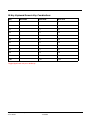
38-Key Keyboard Alpha Key Combinations
Key
Blue Mode
Alpha Base
Alpha Shift
Alpha Caplock
Alpha Shift Caplock
ESC
Delete
ESC
ESC
ESC
ESC
SFT
*Toggle Upper/
Lower/Shift
*Toggle Upper/
Lower/Shift
*Toggle Upper/
Lower/Shift
*Toggle Upper/
Lower/Shift
*Toggle Upper/Lower/
Shift
Blue
Blue Mode
Blue Mode
Blue Mode
Blue Mode
Red
Red Mode
Red Mode
Red Mode
Red Mode
ALPH
Start
Num Mode
Num Mode
Num Mode
Num Mode
Light
Suspend
Keyboard Light
Keyboard Light
Keyboard Light
Keyboard Light
Left
Left
Left
Left
Left
Up
Volume up
Up
Up
Up
Up
Down
Volume down
Down
Down
Down
Down
Right
Insert
Right
Right
Right
Right
OK
OK
OK
OK
OK
OK
Tab
Backtab
Tab
Tab
Tab
Tab
Period
p
P
P
p
Comma
r
R
R
r
0
q
Q
Q
q
1
k
K
K
k
2
l
L
L
l
3
m
M
M
m
4
f
F
F
f
5
g
G
G
g
6
h
H
H
h
7
a
A
A
a
8
b
B
B
b
9
c
C
C
c
-
d
D
D
d
+
i
I
I
i
4-8
Rev C
4/30/2008
Dolphin® 7850 Mobile Computer
User’s Guide
38-Key Keyboard Alpha Key Combinations
Key
Blue Mode
Alpha Base
Alpha Shift
Alpha Caplock
Alpha Shift Caplock
\
n
N
N
n
/
s
S
S
s
F1
u
U
U
u
F2
*
v
V
V
v
F3
@
w
W
W
w
F4
#
x
X
X
x
F5
y
Y
Y
y
F6
z
Z
Z
z
F7
t
T
T
t
F8
o
O
O
o
F9
j
J
J
j
F10
e
E
E
e
*Toggle Upper/Lower only on a double-tap.
**Single-tap of SFT key changes shift mode for just the next character. Double-tap of SFT key toggles Caplock.
***Single tap of BLUE key changes mode for just the next character. Double tap toggles Num/Alpha.
Dolphin® 7850 Mobile Computer
User’s Guide
Rev C
4/30/2008
4-9
38-Key Keyboard Numeric Key Combinations
Key
Blue Mode
Num Mode
Num Shift
ESC
Delete
ESC
ESC
SFT
*Toggle Upper/Lower/Shift
*Toggle Upper/Lower/Shift
*Toggle Upper/Lower/Shift
Blue
Blue Mode
Blue Mode
Red
Red Mode
Red Mode
ALPH
Start
Alpha Mode
Alpha Mode
Light
Suspend
Keyboard Light
Keyboard Light
Left
Left
Left
Up
Volume up
Up
Up
Down
Volume down
Down
Down
Right
Insert
Right
Right
OK
OK
OK
OK
Tab
Backtab
Tab
Tab
Period
.
>
Comma
"
<
0
0
)
1
1
!
2
2
@
3
3
#
4
4
$
5
5
%
6
6
^
7
7
&
8
8
*
9
9
(
-
-
-
+
+
+
4 - 10
Rev C
4/30/2008
Dolphin® 7850 Mobile Computer
User’s Guide
38-Key Keyboard Numeric Key Combinations
Key
Blue Mode
Num Mode
Num Shift
\
\
}
/
/
{
F1
F1
F1
F2
*
F2
F2
F3
@
F3
F3
F4
#
F4
F4
F5
F5
F5
F6
F6
F6
F7
F7
F7
F8
F8
F8
F9
F9
F9
F10
F19
F10
*Toggle Upper/Lower only on a double-tap.
Dolphin® 7850 Mobile Computer
User’s Guide
Rev C
4/30/2008
4 - 11
4 - 12
Rev C
4/30/2008
Dolphin® 7850 Mobile Computer
User’s Guide
5
Using the Imager Scanner Engine
Overview
The Dolphin terminal houses a compact imager scanner engine that uses Adaptus™ Imaging Technology
5.0 which instantly reads all popular 1D and 2D bar codes and supports omni-directional aiming and
decoding. This engine can also capture digital images, such as signatures and pictures of damaged
inventory.
Available Engines
5100 Standard Range (5100SR)
5300 Standard Range (5300SR)
8.3 mil
Linear
Working
Range:
(.020 cm)
10 mil
PDF417
(.025 cm)
13 mil UPC
15 mil
Data Matrix
(.033 cm)
(.038 cm)
15 mil QR
(.038 cm)
35 mil
MaxiCode
(.089 cm)
Near
3.5 in.
(8.9 cm)
3.1 in.
(7.9 cm)
2.1 in.
(5.3 cm)
2.3 in.
5.8 cm)
3.1 in.
(7.9 cm)
2.0 in.
(5.1 cm)
Far
7.6 in.
(19.3 cm)
9 in.
(22.9 cm)
13.2 in.
(33.5 cm)
10.2 in.
(25.9 cm)
8.8 in.
(22.4 cm)
13.0 in.
(33 cm)
5100 Smart Focus (5100SF)
5300 Smart Focus (5300SF)
6.6 mil
PDF417
Working
Range:
(.017 cm)
7.5 mil
Linear
(.019 cm)
10 mil
Linear
(.025 cm)
10 mil
PDF417
(.025 cm)
13 mil UPC
15 mil
Data Matrix
(.033 cm)
(.038 cm)
Near
2.7 in.
(6.8 cm)
2.4 in.
(6.1 cm)
2.1 in.
(5.3 cm)
2.1 in.
(5.3 cm)
1.9 in.
(4.8 cm)
1.7 in.
(4.3 cm)
Far
5.9 in.
(14.9 cm)
6.4 in.
(16.2 cm)
7.5 in.
(19 cm)
7.5 in.
(19 cm)
8.8 in.
(22.3 cm)
7.4 in.
(18.8 cm)
Dolphin® 7850 Mobile Computer
User’s Guide
Rev C
4/30/2008
5-1
Available Laser Engines
In the future, you will be able to select one of the following laser engines for the Dolphin 7850 terminals:
High Performance (HP)
5 mil
55 mil
reflective
Near
2.75 in
(0.07 m)
5 in
(0.13 m)
Far
7 in
(0.17 m)
50 in
(1.27 m)
10 mil
100 mil
reflective
Near
10 in
(0.25 m)
66 in
(1.67 m)
Far
24 in
(0.6 m)
232 in
(5.9 m)
Working Range:
Long Range (LR)
Working Range:
Advanced Long Range (ALR)
13 mil
100 mil
reflective
Near
18 in
(0.45 m)
102 in
(2.6 m)
Far
39 in
(1 m)
363 in
(9.2 m)
Working Range:
5-2
Rev C
4/30/2008
Dolphin® 7850 Mobile Computer
User’s Guide
Supported Bar Code Symbologies
Symbology Type
Symbology Name
1D Symbologies
Codabar
Code 3 of 9
Code 11
Code 32 Pharmaceutical (PARAF)
Code 93
Code 128
EAN with Add-On
EAN with Extended Coupon Code
EAN-8
EAN-13
GS1-128
GS1 Databar
Interleaved 2 or 5
2D Symbologies
Aztec
Codablock
Code 16K
Code 49
Composite
Data Matrix
GS1 Databar
MaxiCode
Micro PDF
OCR
PDF417
QR Code
Composite Codes
Aztec Mesa
Codablock F
EAN·UCC
GS1 Databar-14
OCR
OCR US Money Font
MICR (E 13 B) and SEMI Font
OCR-A
OCR-B
Postal Codes
Postnet and most international 4-state codes
Australian Post
British Post
Canadian Post
China Post
Japanese Post
KIX (Netherlands) Post
Korea Post
Planet Code
Dolphin® 7850 Mobile Computer
User’s Guide
Rev C
4/30/2008
ISBT 128
Matrix 2 of 5
MSI
Plessey
PosiCode
Straight 2 of 5 IATA
Straight 2 of 5 Industrial
Telepen
Trioptic Code
UPC
UPC-A
UPC-E
5-3
Activating the Engine
The Dolphin terminal features a scan trigger on the front of the integrated pistol-grip handle that activates
the scan engine.
Scan Trigger
Using Demos
Demos are software utilities loaded on all Dolphin terminals that demonstrate the advanced features of
the terminal. Two Demos feature the scan engine: Image Demo and Scan Demo.
To access these demos, tap Start > Demos,
• Select Image Demo to verify imaging, or
• Select Scan Demo to verify decoding.
For more information about Demos, refer to the Dolphin Demos User’s Guide, which is available for
download from www.honeywell.com/aidc.
LEDs
The LEDs in the center of both keyboards (for location, see LEDs on page 4-1) light when using the scan
engine.
Scan LED
The LED on the right lights red when you press the scan trigger in scanning applications.
Decode LED
The LED on the left lights green when a scanned bar code is successfully decoded.
5-4
Rev C
4/30/2008
Dolphin® 7850 Mobile Computer
User’s Guide
Decoding
The Dolphin terminal supports two types of image decoding: full-area imaging and Advanced Linear
Decoding (ALD).
Full-area Imaging
Full-area imaging means that the Dolphin terminal support omni-directional aiming, which
means that a positive read can be obtained from many positions. For details, see OmniDirectional Scanning Positions on page 5-4.
ALD
ALD provides fast reading of linear (1D) and stacked linear bar codes (e.g., PDF417). For the
best read, the aiming pattern should be centered horizontally across the bar code. When ALD
is enabled, the reader does not read matrix or postal codes.
To Decode a Bar Code
1.
Tap Start > Demos > Scan Demo.
2.
Position the Dolphin terminal over one of the sample bar codes on page 5-5.
A range of 4–10 inches (10–25 cm) from the bar code is recommended.
3.
Project the aiming pattern by pressing and holding the Scan trigger. The Scan LED lights red.
4.
Center the aiming beam over the bar code. The aiming beam should be oriented in line with the bar
code to achieve optimal decoding; see Omni-Directional Scanning on page 5-6.
5.
Release the Scan trigger.
6.
When the bar code is successfully decoded, the decode LED lights green and the terminal beeps.
Sample Bar Codes
You can use the following bar codes to verify decoding:
Sample 128
Sample PDF417
Code 128
PDF417 Test Message
Dolphin® 7850 Mobile Computer
User’s Guide
Rev C
4/30/2008
5-5
Omni-Directional Scanning
Dolphin terminals support omni-directional scanning.
In general, the aiming pattern or beam is smaller when the terminal is held closer to the bar code and
larger when farther from the bar code. Symbologies with smaller bars or elements (mil size) should be
read closer to the terminal whereas larger bars or elements (mil size) should be read farther from the
terminal.
Note: To achieve the best read, the aiming beam should be centered horizontally across the bar code.
5300 High-Vis Aiming Pattern
The red high-vis aiming pattern frames the bar code.
5100 Green Aiming Beam
The green aiming beam projects outward in a straight line across the bar code.
Laser Engines (HP, LR, and ALR)
Laser engines do not support omni-directional scanning.
To achieve a successful scan, you must align the scanner horizontal to the bar code. A red beam appears
across the bar code when the bar code has been read.
5-6
Rev C
4/30/2008
Dolphin® 7850 Mobile Computer
User’s Guide
Capturing Images
The image-capture process is an intuitive, split-second operation for experienced users. By following
basic guidelines, however, new users can easily develop their own technique and, with practice, quickly
learn to adapt to different application environments.
Image Preview
When the imaging process is initiated, the screen displays a preview of the object. This is a
live video image of what the imager is currently viewing and has a slightly degraded
appearance compared to the captured image. This slight degradation is normal; the captured
image has a higher resolution.
File Formats
The Dolphin terminal is capable of saving images in a number of industry-standard file formats
such as BMP, JPG and PNG. The default file format for images is a grayscale JPG. To obtain
the highest quality images, take grayscale images.
File Size
Digital images have a maximum image size of 640 x 480 pixels and an image definition up to
a 256 grayscale. The image quality and related file size are determined by the data
compression method used by the software application used to take the image. The average
size of the image file is approximately 4–8K. However, the size of the image depends on image
content; the more complex the content, the larger the file size.
Taking an Image
1.
Tap Start > Demos > Image Demo.
2.
Point the Dolphin terminal at the object.
3.
Press the scan trigger to activate the engine. The screen displays a preview of the object.
4.
Adjust the Dolphin terminal’s position until the preview on the screen appears as you want it to
appear in the image.
5.
Hold the Dolphin terminal still and release the Scan trigger. The screen flashes and the captured
image appears on the screen.
6.
By default, the image is saved to the My Device folder (Start > Programs > File Explorer > My
Device). To save the image to another location, tap File > Save As.
High-Vis Aiming Pattern
If your Dolphin terminal is configured with an 5300 imager, you can enable the aiming pattern for imaging
in the Image Demo application. For details about the aiming pattern, see Omni-Directional Scanning on
page 5-6.
1. Tap Start > Demos > Imaging Demo > Options menu > Aimer.
2.
The aiming pattern is now enabled for imaging.
Uploading Images
Image files can be transmitted to a host workstation via
• Microsoft ActiveSync and a Dolphin communication peripheral, or
• Over your wireless radio network.
Dolphin® 7850 Mobile Computer
User’s Guide
Rev C
4/30/2008
5-7
5-8
Rev C
4/30/2008
Dolphin® 7850 Mobile Computer
User’s Guide
6
System Settings
Overview
Customizable settings are available from the Start menu. Tap Start > Settings and the Settings screen
opens displaying the Personal tab. Settings consists of three tabs: Personal, System, and Connections.
Personal Tab
System Tab
Connections Tab
Tab
Description
Personal
The Personal tab provides access to personal configuration programs.
For details, see Personal Settings on page 6-2.
System
The Systems tab provides action to programs that monitor and adjust major system
functions. For details, see System Settings on page 6-7.
Connections
The Connections tab provides access to most of the terminal’s communication options.
For details, see the Connections Tab (see page 7-6) in the Communication chapter.
Dolphin® 7850 Mobile Computer
User’s Guide
Rev C
4/30/2008
6-1
Personal Settings
To access the Personal tab, go to Start > Settings. The screen opens displaying the Personal tab.
Icon
Description
See Page
Buttons
Programs hardware buttons to launch applications or execute commands.
6-3
Input
Customizes the SIP. For details.
6-4
Lock
Provides password protection for certain programs on the terminal.
N/A
Menus
Customizes what appears on the Start and New menus.
6-5
Owner
Information
Stores your contact information.
This information will appear on the Today screen.
N/A
Sounds &
Notifications
Sets the sound volume, enables and disables sounds for specific actions,
and sets sound parameters for system notifications.
N/A
Today
Customizes the look and the information displayed on the Today screen.
N/A
Note: Personal settings are stored in RAM memory and are replaced by system defaults after each hard reset. For
more information about resets, see Resetting the Terminal on page 3-15.
6-2
Rev C
4/30/2008
Dolphin® 7850 Mobile Computer
User’s Guide
Buttons
The Buttons setting programs keyboard buttons to launch applications or execute commands. The default
button assignments that appear on the Buttons window are inactive until you enable the HotKeys Power
Tool.
You must enable the HotKeys Power Tool to activate the button assignments in the Buttons setting.
1. Tap Start > Power Tools.
2.
Tap the HotKeys icon once
.
3.
HotKeys is enabled and the button assignments in the Buttons setting are active.
4.
Verify the button assignment by tapping the button on the keyboard.
For more information about HotKeys, refer to the Dolphin Power Tools User’s Guide, which is available
for download from www.honeywell.com/aidc.
Changing Button Assignments
1.
After HotKeys is enabled, tap Start > Settings > Personal tab > Buttons.
Note: The buttons that appear on this window are the only buttons that can be programmed via the Buttons setting.
You cannot add hardware buttons to this window.
2.
Tap on the name of the application in the Assignment column and select a program or command in
the Assign a program drop down list.
3.
Tap OK to save.
Available Programs
The Assign a program list contains the applications installed on the terminal. If there is a program
installed that you would like to see in this list, paste a Shortcut to the program in the \\Windows\Start
Menu\Programs folder.
For instructions about creating shortcuts, see Using File Explorer on page 6-5.
Dolphin® 7850 Mobile Computer
User’s Guide
Rev C
4/30/2008
6-3
Commands
The Assign a program list also contains the following commands:
Command
Description
<Input Panel>
Opens the soft input panel.
<None>
Nothing happens when the button is pressed.
<OK/Close>
Performs the same function as tapping OK on the screen.
<Scroll Down>
Scrolls down in the open application.
<Scroll Left>
Scrolls left in the open application.
<Scroll Right>
Scrolls right in the open application.
<Scroll Up>
Scrolls up in the open application.
<Start Menu>
Opens the Start menu.
<Today>
Opens the Today screen.
Input Panel Options
You can set input options by going to Start > Settings > Personal tab > Input. The following graphics
are the tab windows where you can customize the SIP (Soft Input Panel) to your preferences:
Input tab
6-4
Word Completion tab
Rev C
4/30/2008
Options tab
Dolphin® 7850 Mobile Computer
User’s Guide
Menus - Modifying the Start Menu
You can add existing programs you use often, such as File Explorer, to the Start menu for faster access.
You are not installing the program, just enabling the user to access the program from the Start menu.
You can add a program to the Start Menu three ways: directly by using the Menus setting, or creating and
pasting shortcuts in File Explorer on the terminal or the workstation (and using ActiveSync to transfer to
the shortcut to the terminal).
Note: Only seven applications total are allowed on the Start menu.
Using the Menu System Setting
1.
Tap Start > Settings > Personal tab > Menus > Start Menu tab.
2.
Tap the check box for the program you want to add and tap OK to save.
3.
Tap the Start menu to verify that the program appears on it.
Using File Explorer
If you do not see the program listed, you can either use File Explorer to move the program or ActiveSync
on the desktop computer to create a shortcut to the program and place the shortcut in the Start Menu
folder.
Note: We recommend that you Copy and Paste Shortcut so that you do not alter your program configurations by
accident. Using Copy and Paste Shortcut (as opposed to Cut/Copy and Paste) ensures that the program files
remain where they need to be for the system to find them to perform system functions.
1.
Tap Start > Programs > File Explorer, and navigate to the program.
File Explorer opens to My Documents by default; to see a list of all folders, tap the folder name and
then My Device.
2.
In File Explorer, navigate to the \Program Files folder. Tap and hold on a program, then select Copy
on the pop-up menu.
Dolphin® 7850 Mobile Computer
User’s Guide
Rev C
4/30/2008
6-5
3.
Navigate to the Windows folder and open the Start Menu folder (My Device > Windows > Start
Menu), tap and hold a blank area of the window, and tap Paste Shortcut on the pop-up menu.
4.
The shortcut is now in the folder.
5.
Tap the Start menu to verify that the program now appears on it.
Using Windows Explorer
Here, you are performing the same basic process as on the terminal, except that you are using the
Explore utility in ActiveSync (Windows Explorer) to copy and paste the shortcut from the workstation to
the terminal. For more details using Explore in ActiveSync, see Exploring the Terminal from the
Workstation on page 7-4.
1. Using a Dolphin peripheral, connect the terminal to the workstation via ActiveSync.
2.
On the workstation, when ActiveSync opens after connecting, tap Explore. Windows Explorer
opens to the files on the terminal.
3.
Navigate to the program.
4.
Right-click on the program and select Create Shortcut.
5.
Select the shortcut, right-click, and select Cut.
6.
Navigate to the Start Menu folder (\Windows\Start Menu).
7.
Right-click on an empty area and select Paste Shortcut.
8.
On the terminal, tap the Start menu and verify that program appears.
6-6
Rev C
4/30/2008
Dolphin® 7850 Mobile Computer
User’s Guide
System Settings
The System tab enables you to verify and sometimes alter system parameters.
To access the System tab, go to Start > Settings > System tab.
•
•
•
•
•
•
•
•
•
•
About (see page 6-7)
Backlight (see page 6-8)
Certificates (see page 6-9)
Clock & Alarms (see page 6-9)
GPS Settings (see page 6-9)
Memory (see page 6-10)
Power (see page 6-12)
Remove Programs (see page 6-14)
Regional Settings (see page 6-13)
Screen (see page 6-15)
About
The About system setting displays specific information about what is loaded on the terminal on three tab
windows:
Tab
Description
Version Tab
Displays the information about the software, operating system, and processor of the
terminal.
The processor for the Dolphin 7850 terminal is an Intel XScale PXA 270 520MHz
processor.
Device ID Tab
Displays the information the terminal uses to identify itself to other devices. It is important
to know this information to identify the terminal when connecting to the network.
Device name: Displays the system’s default name. This is the name used by ActiveSync.
Description: Displays the description of the device ID.
Copyrights Tab
Displays important copyright information.
Dolphin® 7850 Mobile Computer
User’s Guide
Rev C
4/30/2008
6-7
Backlight
The backlight for the color display is user-defined.
Tap Start > Settings > System tab > Backlight.There are two tabs: Battery and External; the options
on each tab are the same.
The Battery tab determines display backlight settings when the terminal is running on battery power.
The External tab determines display backlight settings when the terminal is powered by an external
source, such as a charge cable.
Brightness Tab
The Brightness tab determines the brightness of the display backlight when it’s on.
To disable the backlight, check Disable backlight. Tap OK to save all changes.
6-8
Rev C
4/30/2008
Dolphin® 7850 Mobile Computer
User’s Guide
Certificates
Certificates shows you the network certificates recognized by the operating system. There are personal
and root certificates; each has its own tab.
It is important to verify that the operating system acknowledges your certificate. If the certificate does not
appear on one of these tabs, the operating system does see it, and it will not function properly during the
network authentication process.
For more information, see Certificates on page 8-12.
Clock & Alarms
Clock & Alarms sets the system clock. Appointments, scheduled events, and any function on a schedule
runs off this setting. You need to set the time and date after each hard reset. You can also access this
setting by tapping the date on the Today screen.
GPS Settings
GPS Settings is a Microsoft GPS tool.
Dolphin® 7850 Mobile Computer
User’s Guide
Rev C
4/30/2008
6-9
Memory
Dolphin terminals have two types of memory: volatile and non-volatile. Each type of memory has its own
options.
Volatile
Data stored in volatile memory does not persist through cold boots; see Hard Reset (Cold Boot) on page
3-15. Volatile memory is used for running and storing programs as well as storing program data and is
also known as RAM memory. The Dolphin 7850 terminal has 64MB of volatile memory by default.
Non-Volatile
Data stored in non-volatile Flash memory does persist through cold boots. The Dolphin 7850 terminal can
have 64MB or 128MB of non-volatile memory depending in your configuration.
IPSM (Internal Persistent Storage Manager) is the on-board Flash memory. Because this memory is nonvolatile, data and programs stored in IPSM are not affected when power is removed or a cold boot
launched. For this reason, default programs and files for Dolphin terminals such as Autoinstall are stored
in IPSM.
Use the Memory system setting to check memory usage after you receive warning messages about
memory. There are three tabs: Main, Storage Card, and Running Programs.
Main Tab
This tab displays current capacity and usage of the 64MB or 128MB of on-board, volatile
memory.
6 - 10
Field
Description
Columns
Storage: The part of RAM memory used for storing programs and program data.
Program: The part of RAM memory used to run programs.
Total
Displays the current MB of memory allocated for Storage and Program use.
In use
Displays the total MB of that allocated memory being used in Storage and
Program memory functions.
Free
Displays the total MB of memory available for Storage and Programs use.
Rev C
4/30/2008
Dolphin® 7850 Mobile Computer
User’s Guide
Storage Card Tab
This tab displays the current capacity and usage statistics of the selected memory type: IPSM
or Storage Card. Select the memory type from the drop-down list. IPSM is selected by default.
Field
Description
Total storage card…
The total MB of memory capacity of the selected memory.
In use
The MB currently being used.
Free
The MB that is still available for use.
Drop-down list
IPSM—When IPSM is selected in the drop-down list, the Storage Card tab
displays the IPSM memory capacity and usage statistics.
Running Programs Tab
This tab displays the running software programs using storage memory. Check this tab when
you are receiving out of memory errors or when the mobile computer is running slowly. Select
a program in the list and tap Stop to stop it from running (and therefore from using memory).
Tap Stop All to automatically stop all running programs.
!
Anytime you stop a running program, it frees up volatile memory. Be advised that, when
you stop a program here, any unsaved data in that program is lost. To free up memory
without risking data loss, return to the running program, save your data, and close the
application.
Dolphin® 7850 Mobile Computer
User’s Guide
Rev C
4/30/2008
6 - 11
Find Link
Find searches for large files using storage memory. Clicking Find opens the Search program
with Larger than 64KB already selected in the Type field. Enter the search criteria and tap
Search.
Power
Battery Tab
For more information about the terminal’s batteries, see Battery Power on page 3-11.
Advanced Tab
6 - 12
Determines the amount of time that elapses before the terminal automatically goes into
suspend mode; see Suspend Mode on page 3-15.
You have the option of selecting time periods for both battery and external power.
Field
Description
On battery power
Select the number of minutes of inactivity you want to pass before
the terminal goes into suspend mode when running on battery
power.
On external power
Select the number of minutes of inactivity you want to pass before
the terminal goes into suspend mode when running on external
power.
Rev C
4/30/2008
Dolphin® 7850 Mobile Computer
User’s Guide
Regional Settings
Regional Settings enables you to customize the appearance and formatting to your geographic region.
Specifically, you can customize numbers (i.e., number of decimal places allowed), currency (i.e.,using the
$ or €€ symbol), time, and date.
These specifications apply to all screens, including the Today screen. The Region tab displays an
overview of the region selected in the drop-down list at the top. The terminal is loaded with a number of
pre-programmed regional settings. Select one from the list and the results appear on the screen.
To see specific settings or change a specific setting, tap on one of the tabs, make the change and tap OK
to save it. You need to show reboot the terminal for the changes take effect.
Dolphin® 7850 Mobile Computer
User’s Guide
Rev C
4/30/2008
6 - 13
Remove Programs
The Remove Programs settings enables you to remove programs installed on the terminal. Use this
setting to troubleshoot when you receive messages that the device is out of memory. The programs
removed in the Remove Programs setting are removed from volatile memory.
1. Tap Remove Programs. In the list, select the program you want to remove.
2.
Tap Remove. The following message appears:
3.
Tap Yes. Wait while the program is removed.
4.
Verify that the program no longer appears in the list and the total storage memory adjusts.
Total storage memory available—The available memory adjusts automatically when a program is
removed; see Memory on page 6-10.
6 - 14
Rev C
4/30/2008
Dolphin® 7850 Mobile Computer
User’s Guide
Screen
Note: By default, dynamic screen rotation (i.e., the ability to switch between landscape and portrait orientation) is
disabled on Dolphin 7850 terminals.
Alignment Tab
Tap Align Screen to re-align the screen. Remember, you first align the screen at bootup. You
would need to re-align the screen again if tapping buttons or icons with the stylus no longer
seems to work appropriately.
ClearType Tab
Dolphin terminals support ClearType font rendering. ClearType is a Microsoft technology that
dramatically increases the readability of text on LCD displays.
To enable ClearType font rendering, select Enable ClearType and tap OK.
For more information about ClearType font rendering, visit: www.microsoft.com/typography/
cleartype/what.htm?fname=%20&fsize=
Text Size Tab
Adjusts font scaling within certain views of the Today screen, Contacts, Calendar, Messaging,
and Tasks. This means that you can increase or decrease the point size of the font on
application windows.
Dolphin® 7850 Mobile Computer
User’s Guide
Rev C
4/30/2008
6 - 15
This is the default font size setting. To change the font size, move the slider toward Smallest
or Largest. The Example text changes to reflect the font change. Tap OK to save the new font
size setting.
Default Font Size
6 - 16
Largest Font Size
Rev C
4/30/2008
Dolphin® 7850 Mobile Computer
User’s Guide
7
Communication
Communication Options
Dolphin terminals offer a number of communication options including Microsoft ActiveSync, infrared, and
wireless radios.
I/O Connector
The industrial-grade, 17-pin, mechanical connector on the bottom panel (see I/O Connector on
page 3-9) connects the terminal to a series of Dolphin peripherals that connect to a host
workstation via USB (1.1 or higher).
When the terminal is connected to a host workstation in this way, you can use ActiveSync to
communicate between the host and the terminal. For more information about communicating
with ActiveSync, see Using ActiveSync on page 7-3.
IrDA Port
The IrDA port enables the Dolphin terminal to transmit data via pulses of infrared light to and
from other IrDA-compliant devices, such as printers, PCs, and even other Dolphin terminals.
For more information about communicating via the IrDA port, see Using Infrared
Communication on page 7-8.
Wireless Radios
Dolphin 7850 terminals can be equipped with a WLAN and/or Bluetooth radio. When the
terminal’s radios are enabled, you can connect the terminal to a wireless network for
communication.
For more information about enabling the radios, see Radio Manager on page 7-13.
Software Communication Programs
Dolphin terminals are shipped with the following communication software programs installed.
Microsoft ActiveSync v4.1 or Higher
Microsoft ActiveSync is a tool that enables mobile computing devices to exchange and
synchronize application data with a desktop computer. For more information, see Using
ActiveSync on page 7-3.
Remote Access Services (RAS)
RAS is a feature built into Windows NT that enables users to log into an NT-based LAN using
a modem, X.25 connection or WAN link. RAS is fully supported and allows the use of Point-toPoint Protocol (PPP) or Serial Line IP (SLIP) connections for network connectivity.
To establish a RAS connection, enable the terminal’s radio(s) in the Radio Manager (see page
7-13), set the terminal up on a wireless network, then activate the RASMan Power Tool by
tapping Start > Power Tools > RASMan.
For more information about Power Tools, refer to the Dolphin Power Tools User’s Guide, which
is available for download from www.honeywell.com/aidc.
Dolphin® 7850 Mobile Computer
User’s Guide
Rev C
4/30/2008
7-1
Default Com Port Assignments
The Dolphin terminal ships with the com ports assigned as follows:
Com Port
Assignment
1
Serial port; this is the I/O connector on the bottom panel.
See I/O Connector on page 3-9.
2
Bluetooth Module
If there is no Bluetooth hardware installed on the terminal, this com port is unassigned.
3
Raw Infrared
4
Unassigned
5
USB virtual serial port
6
IrDA, if IrDA is enabled. If IrDA is disabled, this com port becomes available.
7, 8, & 9
Unassigned
These are virtual com ports that are available for selection only when connecting to
devices that use virtual com ports, such as Bluetooth.
Installing Additional Software
Dolphin terminals ship with the operating system, radio drivers, and custom Honeywell software loaded
onto the device. These are the default programs that install when your terminal first boots up. You can
install additional software programs to the terminal provided that the following parameters are met:
• The software program was created for a Windows Mobile device.
• The terminal has enough memory to store and run the program.
• The program has an EXE, CAB, or DLL extension.
The most popular place to find software on the Windows Mobile website: www.microsoft.com/
windowsmobile/products/pocketpc/
!
When selecting programs, verify that the program and version of the program are designed for the Windows
Mobile 5.0 and the terminal’s processor. You can verify your processor by tapping Start > Settings > System
tab > About > Version tab. Make a note of the information in the Processor field.
To install additional software, you can use the communication options described in this chapter.
See,
• Adding Programs via ActiveSync, page 7-4.
• Adding Programs From the Internet, page 7-7.
• Adding Programs via Infrared, page 7-9.
7-2
Rev C
4/30/2008
Dolphin® 7850 Mobile Computer
User’s Guide
Using ActiveSync
ActiveSync communication happens through the I/O connector on the bottom panel (see I/O Connector
on page 3-9) when the terminal is connected to a Dolphin communication peripheral such as the Dolphin
HomeBase device or a charge/communication cable.
Hardware Requirements
• Dolphin HomeBase device or Dolphin communication cable: USB or RS-232
• Power Adapter Cable from Honeywell
Software Requirements
To synchronize, ActiveSync 4.1 or higher must be installed and configured for the appropriate
communication type on the host workstation and the Dolphin terminal. Dolphin terminals ship with
ActiveSync already installed. Therefore, if ActiveSync is already installed on the host workstation, you just
need to connect the Dolphin terminal to the host workstation (via Dolphin peripheral) to initiate
communication.
If ActiveSync 4.1 or higher is not installed on the host workstation, install it from the Getting Started CD
that came with the Dolphin terminal. Insert the CD into the CD-ROM drive of the host workstation and
follow the directions on your screen. You can also download the most current version of ActiveSync from
www.microsoft.com and install.
The host workstation must have Windows 98 Second Edition*, Windows Me, Windows 2000, or Windows
XP installed.
Note: The HomeBase device does not support Windows NT when using a USB connection because Windows NT
does not support USB. *Windows 98 Second Edition provides full USB support.
Setting Up the Host Workstation
To sync successfully, ActiveSync must be configured for same communication type on the host
workstation and the Dolphin terminal. ActiveSync must be setup on your desktop computer before you
initiate synchronization from the terminal for the first time.
Verify that ActiveSync on the host workstation has selected the appropriate communication type by
opening ActiveSync and clicking File > Connection Settings.
For RS-232 communication,
connect to COM1.
For USB communication,
check Allow USB connections.
Note: You can have both USB and RS-232 selected in the software without affecting processing. However, your
hardware setup should use only RS-232 or USB, not both.
Dolphin® 7850 Mobile Computer
User’s Guide
Rev C
4/30/2008
7-3
Setting Up the Terminal
!
When communicating via ActiveSync, your terminal is designed to be connected to the host workstation with
a communication peripheral sold/manufactured by Honeywell, such as the charge/communication cable. Use
of any peripheral not sold/manufactured by Honeywell may cause damage not covered by the warranty.
You need to connect the Dolphin peripheral to the host workstation, then connect the Dolphin terminal to
the peripheral. ActiveSync should attempt to connect automatically and self-configure to RS-232 or USB.
Dolphin terminals default to USB communication.
Verify the connection setting on the Dolphin terminal by tapping Start > Programs > ActiveSync > Menu
> Connections.
USB
The default workstation synchronization value for USB communication is ‘USB
Connection.
RS-232
The default workstation synchronization value for RS-232 communication ‘115200 Default.
Synchronizing with the Host Workstation
After setup, synchronization begins automatically whenever the terminal’s I/O connector connects to a
Dolphin peripheral that is connected to a host workstation with ActiveSync installed.
Note: If you have a wireless LAN card, you can also synchronize remotely.
Exploring the Terminal from the Workstation
When the terminal and desktop computer are connected, open the main ActiveSync window (on the
desktop), and click Explore.
The Mobile Device folder opens in Windows Explorer.
The Dolphin terminal is now treated as a mass storage device, and transferring files is as simple as
dragging and dropping or copying and pasting as you would for moving files between folders on your hard
drive.
Adding Programs via ActiveSync
!
When selecting programs, verify that the program and version of the program are designed for Windows
Mobile 5.0 and your processor. You can verify your processor by tapping Start > Settings > System tab > About
> Version tab. Make a note of the information in the Processor field.
Generally, software for Windows Mobile devices must be installed to the host workstation first, then
transferred to the Dolphin terminal.
7-4
Rev C
4/30/2008
Dolphin® 7850 Mobile Computer
User’s Guide
1.
Download the program to the workstation from either the Internet or the installation CD. You may
see a single *.exe or setup.exe file, a *.cab file, or *.dll. (There may also be several versions of files
for different device types and processors.)
2.
Read any installation instructions provided by the program, such as Read Me files or other
documentation. Many programs provide special installation instructions.
3.
Connect the terminal to the workstation via Dolphin communication peripheral.
4.
Confirm that ActiveSync activates.
If the Program File is Self-Extracting
This type of program installs to the workstation and the terminal simultaneously; one process installs to
both devices.
1. On the workstation, double-click the *.exe or *.setup.exe file. The installation wizard begins.
2.
Follow the directions on the workstation screen. The installation process includes transferring the
software to the terminal via ActiveSync.
If the Program File is Not Self-Extracting
Some programs cannot be installed on workstations because they are designed exclusively for Windows
Mobile devices. In these cases, the appropriate files must be stored on the host workstation and
transferred to the terminal via ActiveSync Explore.
Note: You know that the program is not an installer because an error message stating that the program is valid but
designed for a different type of computer appears when you try to install the program on the workstation.
1.
If you cannot find any installation instructions for the program in the Read Me file or documentation,
open ActiveSync and click Explore.
2.
Navigate to the My Windows Mobile-Based Device folder and copy the program file or files to the
Program Files folder on the terminal. If you want the program to be part of the Autoinstall that
occurs after every hard reset, place the program file in the Autoinstall folder
(\\IPSM\AutoInstall).
3.
On the terminal, tap Start > Programs > File Explorer and navigate to the folder where the
program is located.
4.
Tap on the program file to install it.
If you copied the file to the Autoinstall folder, you can also choose to install the program by
performing a hard reset. The program installs as part of initialization.
5.
After installation is complete, access the program by tapping Start > Programs and the program
appears on the Programs screen. Tap the icon to open the program.
For Additional Help
You can find more information on the host workstation by clicking Help > Microsoft ActiveSync Help.
You can find more information on the terminal by tapping Start > Programs > Help > ActiveSync.
For more information, go to the Windows Mobile software website at: www.microsoft.com/
windowsmobile/products/pocketpc/
Dolphin® 7850 Mobile Computer
User’s Guide
Rev C
4/30/2008
7-5
Connections Tab
The Connections Tab of Windows Mobile Settings provides access to the configuration settings for many
of the terminal’s communication options. Tap Start > Settings > Connections tab.
Note: The programs that appear on the Connections tab depend on the terminal’s radio configuration.
Program
Description
See Page
Beam
Controls infrared communication.
7-8
Connections
Accesses the connections manager to set up modem
connections.
7-10
Network Cards
Opens the network adapters tool.
7-12
Radio Manager
Enables and disables installed radio drivers.
7-13
USB to PC
Toggles the terminal between RNDIS USB and Serial USB
communication. Dolphin terminals default to Serial USB.
7-15
7-6
Icon
Rev C
4/30/2008
Dolphin® 7850 Mobile Computer
User’s Guide
Connecting the Terminal to a Wireless Network
Establishing the terminal on a wireless network depends heavily on your network infrastructure. You will
need specific information from your network administrator.
Whatever your network specifics, some general steps apply:
1. The on-board radio drivers must be enabled for the terminal to transmit a signal. Verify the radio’s
status in the Radio Manager (see page 7-13).
2.
Enter the appropriate configuration settings for each radio installed. Each radio has its own
configuration program.
•
•
For details about configuring the WLAN radio, refer to the Honeywell WLAN Security Supplement User’s
Guide, which is available for download from www.honeywell.com/aidc.
For details about Bluetooth radio, see Wireless PAN Communication with Bluetooth on page 8-1.
Connecting the Terminal to an ISP
This method uses an external modem rather than a wireless radio. For instructions, see Proxy Server
Connections on page 7-11.
Adding Programs From the Internet
When you have established a network connection (via modem or wireless radio), you can access the
Internet and download additional software programs.
!
When selecting programs, verify that the program and version of the program are designed for the Windows
Mobile 5.0 and the terminal’s processor.
1.
Verify the terminal’s processor by tapping Start > Settings > System tab > About > Version tab.
Make a note of the information in the Processor field.
2.
Open Pocket Internet Explorer and navigate to the program’s location. You may see a single *.exe
or setup.exe file, or several versions of files for different device types and processors.
3.
Select the program version that matches the terminal and processor.
4.
Read any installation instructions provided by the program, such as Read Me files or other
documentation. Many programs provide special installation instructions.
5.
Download the program to the terminal straight from the Internet.
You would normally store the program in the \Program Files folder unless another location is
required by the program.
6.
On the terminal, tap the installer file, often an*.exe file.
7.
The installation wizard for the program begins.
8.
Follow the directions on the screen to complete installation.
Dolphin® 7850 Mobile Computer
User’s Guide
Rev C
4/30/2008
7-7
Using Infrared Communication
The IrDA port sends and receives data between the terminal and other devices equipped with infrared.
The maximum data transfer speed is 115 Kbps with a duty cycle of 18.75%.
IrDA Port Location
IrDA Port
Verify Beam Settings
By default, the IrDA port is enabled after each hard reset. This means that the IrDA port is ready to send
and receive data via infrared. Tap Start > Settings > Connections tab > Beam.
Receive all incoming beams… must be checked for the terminal to receive infrared data from another
device.
Sending Data
You can send and receive information via infrared, including software programs (.exe files).
To send or receive, the IrDA ports of both devices must be aligned with each other and within a close
range. The maximum data-transfer speed is 115 Kbps.
1. Align the IrDA ports of both devices. (When sending data from one Dolphin terminal to another, position both terminals so that the IrDA ports are facing each other directly.)
2.
7-8
Open the program where you created the item you want to send and locate the item in the list.
You can beam files, but not folders, from File Explorer.
Rev C
4/30/2008
Dolphin® 7850 Mobile Computer
User’s Guide
3.
Tap and hold the item and select Beam File.
4.
The information begins transmitting to the other infrared device.
Receiving Data
1.
Verify that the terminal is set to receive all incoming beams; see Verify Beam Settings on page 7-8.
2.
Align the IrDA ports.
3.
Have the owner of the other device send the information to you via infrared.
4.
Your terminal automatically begins receiving it.
Adding Programs via Infrared
Select a program on one terminal and beam it to another to load additional software programs to Dolphin
terminals.
Troubleshooting
If the Beam Settings are not set to receive or you’ve aligned two IrDA ports and the terminal is still not
receiving, tap Start > Programs > Infrared Receive. The terminal searches for the sending device.
If the terminal cannot find the sending device, the following message appears:
Dolphin® 7850 Mobile Computer
User’s Guide
Rev C
4/30/2008
7-9
Connections Manager
The connections manager sets up various network connections to Internet Service Providers (ISPs) via
an external modem.
If you are using one of the on-board wireless radios to connect to a network, do not enter network
parameters in the connections manager. The Dolphin terminal uses the radio’s settings to connect to the
network.
Note: All server-assigned IP addresses use Dynamic Host Configuration Protocol (DHCP). The zero-config WLAN
feature of Windows Mobile is disabled on Dolphin terminals.
To open the connections manager, tap Start > Settings > Connections tab > Connections icon
The connection manager opens displaying the Tasks tab.
.
Task Tab
The Task tab enables you to initially configure, then manage network settings when using a modem.
Select an item in this list and then complete the setup screens that follow with the appropriate information
for your network.
My ISP
The links under this heading enables you to add and manage modem connections to an ISP. To complete
the setup screens, obtain the following information from your ISP:
•
•
•
•
ISP dial-up access telephone number
Username
Password
TCP/IP settings
My Work Network
These links enable you to establish the following connections types:
•
•
•
Modem
Virtual Private Network (VPN)
Proxy server connection
To complete the setup screens, obtain the network parameters from your system administrator.
7 - 10
Rev C
4/30/2008
Dolphin® 7850 Mobile Computer
User’s Guide
Proxy Server Connections
If you are connected to your ISP or private network during synchronization, the terminal should download
the proper proxy settings during synchronization with the workstation. If these settings are not on your
workstation or need to be changed, ask your ISP or network administrator for the proxy sever name,
server type, port, type of Socks protocol used, and your user name and password.
Modify an Existing Connection
Manage Existing Connections appears on the Connections tab after at least one network connection
has been established. Tap Manage Existing Connections on this tab and follow the setup screens. You
will usually be walked through the same setup screens used to establish the connection.
Advanced Tab
The Advanced tab enables you to select the default network, dialing rules, and IP address exceptions for
modem connections.
Note: You should not need to change Advanced settings because most ISPs now use DHCP addresses.
Online Help
For more information about modem connection setup, consult the online help on the setup screens by
tapping the Help icon
.
Dolphin® 7850 Mobile Computer
User’s Guide
Rev C
4/30/2008
7 - 11
Network Cards
The Connections tab (see Connections Tab on page 7-6) contains a Network Cards icon
displays the network cards installed in the terminal.
1. Tap Start > Settings > Connections > Network Cards
that
2.
Tap on an adapter in the list to review its settings. (Server-assigned IP addresses use DHCP.)
3.
If you make a change on one of these tabs, tap OK to confirm the changes.
4.
You must perform a soft reset to update the registry entries; see Soft Reset (Warm Boot) on page 315. During the soft reset, the new registry entries are created and can be read by the applications
that need them.
!
7 - 12
Do NOT perform a Hard Reset (Cold Boot) (see page 3-15) after modifying an adapter here. Hard resets return
the terminal to factory defaults, which erases network adapter modifications made here.
Rev C
4/30/2008
Dolphin® 7850 Mobile Computer
User’s Guide
Radio Manager
The Radio Manager enables and disables the radio drivers installed in the terminal. When a radio is
enabled, the radio is transmitting a signal. When disabled, the radio is not transmitting a signal.
At least one radio must be enabled before you can set the terminal up on a wireless network. After the
radio is enabled, you can enter the appropriate network parameters for your network. If the radio is
disabled, the terminal doesn’t connect.
Dolphin 7850 terminals can be configured with a WLAN and/or Bluetooth radio.
Radio Driver Installation
For a radio to show up in the Radio Manager, both the hardware module and the software driver for each
radio must be installed in the terminal. The radio will appear in the Radio Manager if the module is present
but cannot be enabled if the associated driver is not installed as well. All radios and radio drivers are colocated inside the terminal.
Radio drivers (.cab files) are stored in the Autoinstall folder and install during the Autoinstall process after
each hard reset (see page 3-15). Only the appropriate drivers for the terminal’s radio configuration install.
For more information about Autoinstall, refer to the Dolphin Power Tools User’s Guide, which is available
for download at www.honeywell.com/aidc.
Enabling the Radios
The terminal enables the WLAN radio after each hard reset by default. Verify the status of the radio before
attempting to establish or change network connection settings.
1.
Tap Start > Settings > Connections tab > Radio Manager .
The Radio Manager appears identifying that radios and radio combinations that can be enabled.
2.
Select the radio or radio combination in the list and tap Apply. The Radio Manager attempts to
enable the radio.
3.
When the radio is enabled, the Status field reads “Success.” If an error occurs during a radio mode
change, an error message appears in the Status field and the change is abandoned.
Dolphin® 7850 Mobile Computer
User’s Guide
Rev C
4/30/2008
7 - 13
Radio Manager Window
Field
Description
Radio Modes
Displays the radio hardware modules currently installed on the terminal.
Status Field
Provides feedback on the state of the radio. The Status field reads “Ready” when the
selected radio is enabled and the Radio Manager is ready to receive a command.
Otherwise, the Status field displays the following messages when enabling a radio:
• Success=The radio or radio combination has been successfully enabled.
• WLAN error messages=Indicate that the radio could not be enabled.
Disabling Radios
To power down all radios, select None and tap Apply. All radios are disabled.
7 - 14
Rev C
4/30/2008
Dolphin® 7850 Mobile Computer
User’s Guide
USB to PC
The USB to PC applet enables you to switch between RNDIS (Remote Network Driver Interface
Specification) USB and Serial USB communication.
Dolphin 7850 terminals default to Serial USB. Honeywell recommends using Serial USB.
To change this setting, tap Start > Settings > Connections tab > USB to PC
is not selected, which indicates Serial USB.
. The enable option
To switch to RNDIS USB, select Enable advanced network functionality and tap OK to save. (Wait as
the terminal makes the change.)
Dolphin® 7850 Mobile Computer
User’s Guide
Rev C
4/30/2008
7 - 15
7 - 16
Rev C
4/30/2008
Dolphin® 7850 Mobile Computer
User’s Guide
8
Wireless PAN Communication with Bluetooth
Bluetooth Radio
The on-board Bluetooth radio is enabled by default at startup and operates within the 2.4 GHz–2.48 GHz
band. Bluetooth transmissions hop between 79 separate frequencies 1,600 times every second, and with
a communication range of about 10 meters (class II).
Enabling the Bluetooth Radio
The Bluetooth radio must be enabled in order to connect to other devices. You’ll know that the radio is
not enabled if there is a yellow explanation point over the Bluetooth icon
.
By default, the WLAN radio is enabled after each hard reset. Therefore, you must enable the Bluetooth
radio in the Radio Manager (see page 7-13). Tap Start > Settings > Connections tab > Radio Manager.
Select Bluetooth Only or Wi-Fi/Bluetooth, then tap OK to enable the radio.
BTExplorer
BTExplorer discovers Bluetooth devices in range and presents them in an easy-to-understand format
similar to Windows Explorer. BTExplorer visually separates trusted (paired) and untrusted remote devices
and identifies friendly names and services of remote devices. Custom icons indicate the device class
(type) as well as available services.
The services supported by the local device include
•
•
•
•
•
•
•
File transfer
OBEX
OBEX object push
FAX
LAN access
Dial-up networking
Serial port communication
Pairing, security, and encryption settings can be configured for the local device. In addition to the
configuration options available, any of the supported services may be added to or removed from the local
device.
Dolphin® 7850 Mobile Computer
User’s Guide
Rev C
4/30/2008
8-1
Accessing BTExplorer
When the Bluetooth radio is enabled, the Bluetooth icon on the Today screen appears as follows
Tapping this icon once opens BTExplorer to the Favorites window.
.
Note: When the Bluetooth radio is disabled, tapping this icon opens a warning message, which states that the radio
is not enabled and to go to the Radio Manager as described in Accessing BTExplorer on page 8-2.
8-2
Rev C
4/30/2008
Dolphin® 7850 Mobile Computer
User’s Guide
Using BTExplorer
BTExplorer has a New Connection Wizard for each type of Bluetooth connection you want to make; see
Connection Types on page 8-7. You open BTExplorer, select the connection type, BTExplorer scans for
matching devices and services, and the connection wizard walks you through the connection process.
Different connection types will require different information. Make sure you have all the necessary
information (PIN numbers, passkeys, MAC addresses, etc.) from the devices you want to connect to.
1.
When the Bluetooth radio is enabled, tap the Bluetooth icon on the Today screen once
plorer opens to the Favorites window.
. BTEx-
BTExplorer always opens to the Favorites window, which displays the Bluetooth connections saved
as Favorites on the terminal. Use this window as a quick way to connect to established Bluetooth
connections.
2.
Tap File > New Connection and the New Connection Wizard opens.
3.
Select the action you want to perform from the drop-down list below.
Dolphin® 7850 Mobile Computer
User’s Guide
Rev C
4/30/2008
8-3
4.
Click Next and BTExplorer scans for other Bluetooth devices in range and displays the search
results.
5.
Select a device and click Next. BTExplorer attempts to connect to the selected device and explore
the device’s available services.
6.
Select a service in the list and tap Next. The next window enables you to save the device connection
and service as a Favorite.
a. Leave Save As Favorite selected to save this connection as a Favorite and type in the Favorite
Name. If not, uncheck the option.
8-4
Rev C
4/30/2008
Dolphin® 7850 Mobile Computer
User’s Guide
b. Review the contents of the window and tap Next. The connection summary appears.
7.
Tap Connect. If you are transferring files, the next steps are to select the file(s) and transfer them to
the device.
8.
While the terminal is transferring data, the icon on the Today screen will display a green, doublesided arrow over the Bluetooth icon
9.
.
The next time you open BTExplorer, any connection you saved as a Favorite will appear.
Dolphin® 7850 Mobile Computer
User’s Guide
Rev C
4/30/2008
8-5
Favorites
BTExplorer enables you to save connections to specific devices and the services on those devices as
Favorites. Each time you try to connect to a device and service manually, you are asked if you want to
save the connection as a Favorite. You can even give each connection a unique name.
Favorite connections appear on the opening window each time you open BTExplorer.
Just tap and hold on the Favorite and the list and select Connect on the popup menu to connect to that
device and service(s).
Favorites do persist through cold boots.
Navigation Buttons
Bluetooth Explorer contains the following navigation buttons at the bottom of ever wizard screen:
Back
Move back on screen in the wizard.
Cancel
Cancel the setup and return to the New Connection window.
Next
Save the information on the current setup screen and move to the next.
8-6
Rev C
4/30/2008
Dolphin® 7850 Mobile Computer
User’s Guide
Connection Types
Connection Type
Allows the Bluetooth radio to…
Requirements
Explore Services on
Remote Devices
Discover available services.
Discoverable Bluetooth devices with
activated services must be in range
for the terminal to retrieve devices and
services.
Pair with Remote
Device
Pair with remote devices.
The correct PIN number of the device
you’re attempting to pair with.
ActiveSync via
Bluetooth
Synchronize files and data with a remote
workstation via Bluetooth ActiveSync.
Matching Bluetooth ActiveSync
settings.
Browse Files on
Remote Device
See files on a remote device.
A working Bluetooth connection with
the remote device.
Connect to Internet
using Access Point
Connect to the Internet using LAN or a
network gateway.
A Bluetooth-compatible access point.
Connect to Internet
using Phone/Modem
Connect to the Interne using a mobile
phone or mobile phone modem using dialup networking.
Dial-up account information.
Connect to Personal
Area Network (PAN)
Connect to another Bluetooth device that
allows participation in a PAN.
Another device that is set up as part
of an existing PAN.
Send or Exchange
Objects
Send or exchange business cards,
contacts, pictures, appointments, and tasks
with another Bluetooth device.
A working Bluetooth connection to a
remote device.
Associate Serial Port
Make a favorite to a Bluetooth serial port device.
Dolphin® 7850 Mobile Computer
User’s Guide
Rev C
4/30/2008
8-7
Device Types
BTExplorer supports the following device types:
•
•
•
•
•
•
Audio Devices
Network Devices
Phones
Printers
Computers
OBEX Devices
By default, BTExplorer scans for Network Devices.
To change the, device type, tap on the arrow to the right of the heading on the left. The name of this
heading changes depending on what device type is selected; it can say “Filter” or “Bluetooth Devices.”
Select another device type in the list.
View Options
Discovered Devices appear with an icon indicating what type of device it is and the Device ID.
By default, the discovered devices screen appears in the Large icon view. The Details menu offers you
alternate view options. (When you select the Details menu, its name changes to “View.”)
Large Icons
Displays large icons in the viewing area.
List
Displays small icons in a one-column list.
Details
Displays small icons in a list with two columns:
Remote Device Name The Device ID.
8-8
Device Address
The MAC address.
Trusted
The status of this device.
Trusted=The device is trusted.
False=The device is not trusted.
Rev C
4/30/2008
Dolphin® 7850 Mobile Computer
User’s Guide
Menu Options
The discovered devices window has a popup menu that enables you to perform several tasks. You can
select a device and tap and hold or just tap and hold on an empty space; he same menu appears. Certain
menu items are enabled or disabled depending on which method you use.
Menu Item
Description
Discover Devices
Scans for Bluetooth devices.
Discover Names
Scans for device names.
View
Opens a side menu that offers you sorting options for
the discovered devices list.
• All Devices–Shows all devices in the vicinity.
• Trusted Devices Only–Removes untrusted
devices from the display.
• Untrusted Devices Only–Removes trusted
devices from the display.
Note: These options affect only what appears on the
display, not what devices the Bluetooth radio
has discovered.
Delete All Devices
Deletes all the discovered devices.
*Delete Device
Deletes a selected device.
*Properties
Displays the properties of a selected device.
Tap OK (either one) to return to the discovered
devices window.
Refresh
Scans for Bluetooth devices.
*These items are active only when a device is selected when the pop-up menu appears.
Dolphin® 7850 Mobile Computer
User’s Guide
Rev C
4/30/2008
8-9
Discovered Devices
In order for the terminal to find a device when scanning, that device must be Discoverable by Bluetooth.
If not, the terminal won’t find the device when scanning. Furthermore, the device must have activated
Bluetooth services. The terminal will retrieve only discoverable devices and the services activated on that
device.
Refreshing Discovered Devices
If your Bluetooth device doesn’t show up in the list, scan again by tapping and holding on the window and
selecting Refresh on the pop-up menu.
Note: By default, this window displays the devices found on the first search but does not refresh automatically when
you open it again. If you make any changes to the discoverable status of a Bluetooth device in range of the
terminal, make sure that you refresh this window.
Making the Terminal Discoverable
If you want other Bluetooth devices (including another Dolphin terminal) to be able to retrieve the terminal
in a scan, you must 1) make it discoverable and 2) activate specific services.
Discoverable status does not persist through cold boots.
1. On the Favorites window, tap Tools > Settings.
8 - 10
Rev C
4/30/2008
Dolphin® 7850 Mobile Computer
User’s Guide
2.
Set Discoverable Mode to Discoverable.
Set Connectable Mode to Connectable.
You must change both for the terminal to be discoverable.
3.
To activate specific services, tap the Services tab and tap Add.
4.
Select a service and tap OK to add.
Dolphin® 7850 Mobile Computer
User’s Guide
Rev C
4/30/2008
8 - 11
5.
Each service you select is going to take you through a series of windows to confirm the parameters
of the service.
For example, for the file transfer service, the following window appears:
6.
Tap OK and you are returned to the prior window, which now displays the service as active.
7.
Repeat Steps #4–6 for the services you want to activate.
8.
The Dolphin terminal and its services are now activated and can be discovered by another Bluetooth
device.
8 - 12
Rev C
4/30/2008
Dolphin® 7850 Mobile Computer
User’s Guide
Pairing
Pairing associates Bluetooth devices with each other so that you don’t have to enter access information
every time a connection is requested. Bluetooth devices need to be paired with each other before
attempting a connection the first time.
Paired devices remain paired, even if:
• One of the devices is not powered.
• A service connection is interrupted or stopped.
• One or both devices are rebooted.
Passkey
Paired devices share a unique passkey both devices use to authenticate when connecting. The passkey
can be alphanumeric, numbers, or letters, and must consist of one or up to 16 characters.
Trusted Devices
Trusted devices are paired devices.
Dolphin® 7850 Mobile Computer
User’s Guide
Rev C
4/30/2008
8 - 13
8 - 14
Rev C
4/30/2008
Dolphin® 7850 Mobile Computer
User’s Guide
9
Dolphin HomeBase Device
Overview
As the hub of your system, the Dolphin HomeBase device charging and communication cradle supports
both RS-232 and USB communication, enabling your terminal to interface with the majority of PC-based
enterprise systems.
Communication
RS-232 transmits data at speeds of up to 115 Kbps. With USB port, the data transmission rate goes up
to 12 Mbps.
HomeBase devices cannot be physically connected to each other–sometimes referred to as “daisychaining”–but can be networked together through serial or USB hubs.
Convenient Storage
Intelligent battery charging makes the HomeBase device a safe and convenient storage receptacle for
your terminal.
Capacity
The HomeBase device can charge two battery packs: the one that’s installed in the terminal seated in the
well and the other in the auxiliary battery well on the back panel. While charging the battery pack in the
terminal, the HomeBase device also powers the Dolphin terminal. The auxiliary battery well charges a
battery pack independently of the terminal well.
Intelligent Battery Charging
The HomeBase device completes a full charge of the main battery pack in less than four(4) hours.
In addition to charging, the HomeBase device powers the intelligent battery charging system in the
terminal that protects the battery from being damaged by overcharging. The terminal senses when a
battery pack is fully charged and automatically switches to a trickle charge that maintains the battery at
full capacity.
As a result, terminals may be stored in the HomeBase device without damage to the terminals, battery
packs, or peripherals.
Power Supply
The HomeBase device is available with US, UK, and European power supplies. Each version is designed
to convert the voltage from the power sources in each geography to the 7.4 volts DC required by the
terminal.
!
Use only the Li-ion battery packs provided by Honeywell. Use of any battery not sold/manufactured by
Honeywell may result in damage not covered by the warranty.
!
Use only the peripherals, power cables, and power adapters from Honeywell. Use of peripherals, cables, or
power adapters not sold/manufactured by Honeywell may cause damage not covered by the warranty.
Dolphin® 7850 Mobile Computer
User’s Guide
Rev C
4/30/2008
9-1
Front Panel
Terminal Well
DOCK
DOCK LED
A UX B ATTE R Y
COMM
AUX Battery LED COMM LED
AUX Battery LED
Indicates status of the battery charging in the auxiliary battery well; see page 9-3.
Orange
Green
The auxiliary battery is charging.
The auxiliary battery has completed charging and is ready for use.
COMM LED
The COMM LED indicates the status of data transfer between the Dolphin terminal and the
host workstation. The color of this LED differs if the HomeBase device is using the serial or
USB port connection.
If using a serial port connection
Red
Green
Orange
Serial data is being sent from the host device to the HomeBase device.
Serial data is being sent from the HomeBase device to the host device.
Serial data is being sent at high data rates.
If using a USB port connection
Green
A USB connection is established with the host workstation.
DOCK LED
Turns solid green when the terminal is properly seated in the HomeBase device. When this
light is on, the terminal is connected to the HomeBase device.
Terminal Well
Place the terminal in this well to communicate with a host device, power the terminal, and
charge its battery pack. The back of the terminal well features a saddle to accommodate the
integrated pistol-grip handle.
9-2
Rev C
4/30/2008
Dolphin® 7850 Mobile Computer
User’s Guide
Back Panel
Handle Saddle
Auxiliary
Battery
Well
DC Power
Jack
RS-232 Port
USB Port
Auxiliary Battery Well
The auxiliary battery well charges an additional Li-ion battery pack independently of the
terminal well. This feature ensures that you can always have a fully-charged battery for your
terminal; see Charging a Spare Battery Pack on page 9-3.
DC Power Jack
Connect the power cable to this power jack; see Powering the HomeBase Device on page 9-5.
Handle Saddle
The curve on the back wall of the terminal well accommodates the pistol-grip handle when the
terminal is seated in the well.
RS-232 Port
For RS-232 data communication, use the 9-pin, RS-232 cable from Honeywell to connect this
port to a peripheral device. For more information, see RS-232 Serial Connector on page 9-6.
USB Port
This USB Port is full-speed, 2.0 compliant, and requires ActiveSync 4.1 or higher. Using a USB
cable, you can connect the HomeBase device to a USB-compliant device. When the
HomeBase device is connected to that device, the terminal is connected to the device when
seated in the terminal well.
The HomeBase device acts as a USB device by interfacing the USB signals of the terminal to
the USB signals of the host workstation; see ActiveSync Communication on page 9-8.
Charging a Spare Battery Pack
The Auxiliary Battery Well (see page 9-3) located on the back panel charges a spare battery. The AUX
Battery LED (page 9-2) on the front panel indicates the charge status of the battery in this well. Charge
time is less than four(4) hours and the charge process is independent of the terminal well.
1. Insert the end of the battery without the locking tab into the bottom of the auxiliary well opening.
Dolphin® 7850 Mobile Computer
User’s Guide
Rev C
4/30/2008
9-3
2.
Snap the battery into place with a hinging motion. The Aux Battery LED lights orange.
3.
The AUX Battery LED monitors the charge progress.
Bottom Panel Dimensions
162.2 mm.
(6.4 in.)
106 mm.
(4.2 in.)
62 mm.
(2.4 in.)
108 mm.
(4.25 in.)
136.3 mm.
(5.37 in.)
78 mm.
(3.1 in.)
9-4
Rev C
4/30/2008
Dolphin® 7850 Mobile Computer
User’s Guide
Powering the HomeBase Device
The terminal requires 9.5 volts DC input for communication and battery charging; the power adapter on
the power cable converts the voltage from the power source to 9.5 volts DC. Only power adapter cables
from Honeywell convert the voltage appropriately.
Plug this connector into the
DC Power Jack on the back
panel.
Power Cable
Power Adapter
1.
Plug the power cable into the power adapter.
2.
Plug the power cable into the power source.
3.
Plug the connector cable into the DC power jack on the back panel. The HomeBase device is now
powered.
When a terminal is properly seated in the terminal well, the HomeBase device powers the terminal,
charges the terminal’s main battery pack, and launches ActiveSync communication (see ActiveSync
Communication on page 9-8).
Honeywell recommends that you leave the HomeBase device connected to its power source at all times,
so that it is always ready to use.
Dolphin® 7850 Mobile Computer
User’s Guide
Rev C
4/30/2008
9-5
RS-232 Serial Connector
The following diagram displays the pins of the RS-232 serial connector of the Back Panel (see page 9-3):
3LQ 'HVFULSWLRQ
,QWHUQDO -XPSHU WR 3LQ 7;'
5;'
'65
*1'
'75
&76
576
5,
Note: Signals referenced are for a DTE device. The HomeBase device is at a right-angle to the printed circuit board
(PCB). The ninth pin has a ring indicator (RI).
9-6
Rev C
4/30/2008
Dolphin® 7850 Mobile Computer
User’s Guide
Charging the Main Battery
The HomeBase device powers the terminal and fully charges its main battery pack in less than four(4)
hours. To check battery power, see Power on page 6-12.
As battery packs charge, the charging circuitry follows the two-step charging process (CC-CV) that is
recommended for Li-ion batteries. The process monitors changes in temperature, current, and voltage.
Inserting a Terminal
1.
Install the battery pack in the terminal; see Install the Main Battery
Pack on page 2-1.
2.
Power the HomeBase device; see Powering the HomeBase
Device on page 9-5.
3.
Slide the terminal into the terminal well until the Dock LED lights
green to indicate that the terminal is properly seated.
4.
The battery pack begins charging.
The intelligent battery charging system in the terminal monitors battery
power and senses when a full charge has been obtained. When
charging is complete, the terminal switches to a trickle charge that
keeps the battery at full charge while resting in the HomeBase device.
Dolphin® 7850 Mobile Computer
User’s Guide
Rev C
4/30/2008
9-7
ActiveSync Communication
The Dolphin terminal ships with ActiveSync already installed and defaulted to USB communication. If
ActiveSync is not installed on your workstation, you must install it. For details, see Using ActiveSync on
page 7-3.
Communication Types
The HomeBase device can communicate via USB or RS-232 using ActiveSync 4.1 or higher. However,
the HomeBase device should have only one type of interface cable connected at a time, either USB or
RS-232.
USB
The USB Port (see page 9-3) on the back panel allows the terminal to communicate with a
workstation or be networked through a USB hub. The HomeBase device acts as a USB
device by interfacing the USB signals of the terminal to the USB signals of the host
workstation.
Maximum data transfer rate is 12 Mbps.
RS-232
The RS-232 Port (see page 9-3) on the back panel allows the terminal to communicate with
a workstation, modem, or any RS-232 device using a standard serial cable and
communication software.
Maximum data transfer rate is 115 Kbps.
Communicating with the Dolphin Terminal
1.
Insert the terminal into the terminal well of the HomeBase device.
•
•
The DOCK LED lights green. If not, make sure that the terminal is properly seated. You may need to
remove and re-insert the terminal.
The terminal activates. If not, verify that the Honeywell power supply is properly connected to the DC
Power Jack (see page 9-3) on the back panel and plugged into a functioning outlet.
2.
The terminal and the workstation automatically open ActiveSync to establish a connection.
3.
The HomeBase device can now transfer data between the terminal and the host workstation. If
communication does not occur, check the port connections to ensure that the cradle is correctly
configured.
Verify Communication
You can verify that the USB driver is functioning by watching the COMM LED on the USB
HomeBase device. When the COMM LED lights solid green, the HomeBase device is
communicating with the workstation.
Verify Data Transfer
The COMM LED flashes when data is being transferred via the HomeBase device. For an RS232 connection, the COMM LED flashes red and green. For a USB connection, the COMM
LED flashes green.
9-8
Rev C
4/30/2008
Dolphin® 7850 Mobile Computer
User’s Guide
RS-232 Cables
Connect the HomeBase device to the host workstation or other device by plugging an RS-232 serial cable
into the RS-232 Port (see page 9-3) on the back panel. The wiring of your cable depends on whether the
other device is set up as a Data Communication Equipment (DCE) or Data Terminal Equipment (DTE)
device.
The HomeBase device is configured as a DCE device. To communicate with another DCE device, use
either a null modem adapter in line with a standard RS-232 cable, or a null-modem serial cable. To
communicate with a DTE device such as a computer, use a standard (or straight-through) RS-232 cable.
You can make your own cables by following the pin configuration in the chart below. To do so, you must
determine if your host RS-232 device is 9-pin or 25-pin, and whether it is configured as a DCE or DTE
device.
RS-232 Pin Configuration
Host Port
(DCE)
IBM AT DB9
(DTE)
IBM XT DB25
(DTE)
Modem DB25
(DCE)
Pin / Input Signal
2
3
5
4
6
7
8
/ (RD)
/ (TD)
/ (SG)
/ (DTR)
/ (DSR)
/ (RTS)
/ (CTS)
2
3
5
4
6
7
8
3
2
7
20
6
4
5
2
3
7
6
20
5
4
Note: HomeBase devices cannot be daisy-chained.
Dolphin® 7850 Mobile Computer
User’s Guide
Rev C
4/30/2008
9-9
Mounting the Dolphin HomeBase Device
Set the HomeBase device on a dry, stable surface, such as a desktop or workbench near an electrical
outlet. Be sure to provide enough workspace with good lighting for the user to view and operate the
terminal while it is seated in the HomeBase device.
When choosing a location, bear in mind that:
• the mounting location must allow users easy access to the auxiliary battery well, and
• the serial and USB ports as well as the power jack face straight out of the rear panel, and you will most
likely want easy access to them in the future.
Desk Mounting
Charging/communication cradles have a DIN rail (7.5 mm high X 35 mm wide) slot on the bottom to allow
for secure desk attachment of the unit if desired.
1.
Slide the DIN rail slot along the bottom panel.
2.
Using the appropriate nuts and bolts, secure the DIN rail to the desk or flat surface.
Note: Use screws that are appropriate for the type of surface (wood or metal, for instance) you are mounting to.
9 - 10
Rev C
4/30/2008
Dolphin® 7850 Mobile Computer
User’s Guide
Wall Mounting
A wall mount kit that contains a screws and a mounting bracket can be purchased separately. The bottom
panel of the HomeBase device contains four(4) rubber feet–one at each corner–that help keep it stable
and secure when resting on a flat surface. Those rubber feet should be removed with pliers before wall
mounting the HomeBase device.
1. Secure screws to the bottom panel by sliding them into the available slots.
2.
Attach the bottom panel to the mounting bracket matching the holes to the secured screws.
3.
Fasten the screws to secure the HomeBase device to the mounting bracket.
4.
Turn the secured HomeBase device right side up.
5.
Using the appropriate screws, secure the mounting bracket to the wall or vertical surface as shown.
Dolphin® 7850 Mobile Computer
User’s Guide
Rev C
4/30/2008
9 - 11
9 - 12
Rev C
4/30/2008
Dolphin® 7850 Mobile Computer
User’s Guide
10
Dolphin QuadCharger Device
Overview
The Dolphin QuadCharger device is a four(4)-slot charging station that can charge a li-ion battery in less
than four(4) hours. The fourth slot features a battery analyzer that completely resets and re-calibrates a
battery and displays its resulting capacity.
The QuadCharger device is compatible with the Li-ion batteries that power Dolphin 7850 terminals.
Intelligent Battery Charging
Each charging slot works independently of the other three.
As battery packs charge, the charging circuitry follows the two-step charging process (CC-CV) that is
recommended for Li-ion batteries. The process monitors changes in temperature, current, and voltage.
The charger also resets and calibrates battery pack data.
!
Use only the Li-ion battery packs provided by Honeywell. Use of any battery not sold/manufactured by
Honeywell may result in damage not covered by the warranty.
!
Use only the peripherals, power cables, and power adapters from Honeywell. Use of peripherals, cables, or
power adapters not sold/manufactured by Honeywell may cause damage not covered by the warranty.
Dolphin® 7850 Mobile Computer
User’s Guide
Rev C
4/30/2008
10 - 1
Front Panel
Charging Slots–with batteries
Charging Slots
Charge/Analyze Slot
Status LEDs
Battery Capacity
Indicator LEDs
Analyze Button
Charge/Analyze LED
Charging Slots
There are four(4) charging slots. Each slot holds one battery. When a battery is placed in a
slot, it immediately begins charging.
Charge/Analyze Slot
This is the fourth slot and the only one that can be used to analyze a battery. When a battery
is placed in this slot, it begins charging just as it does in the other three slots. However, if you
press the ANALYZE button, it runs the battery in this slot through the complete Analyze cycle.
For more information, see Using the Battery Analyzer on page 10-5.
Battery Capacity Indicator LEDs
These LEDs give a readout of the remaining battery capacity after it has run through a
complete analyze cycle. For more information, see Battery Capacity Indicator LEDs on page
10-2.
Analyze Button
Press this button to start a battery analyze cycle; see Using the Battery Analyzer on page 10-5.
Status LEDs
A status LED is located above each of the four(4) battery slots. The color of the LED indicates
the charge status of the batteries in its slot.
Green
Orange
Red
10 - 2
The battery in the slot has completed its charge cycle and is ready to use.
The battery in the slot is being charged at a maximum charge rate.
The battery in the slot encountered an error during the most recent charge cycle.
Rev C
4/30/2008
Dolphin® 7850 Mobile Computer
User’s Guide
Back Panel
Power Switch
Power Supply Connector
Power Supply Connector
Use this connector to attach the power supply to the QuadCharger device.
The universal power supply accepts input voltages between 90-265 volts.
Power Switch
Toggle the power switch to turn the QuadCharger device on and off.
Inserting and Removing Battery Packs
To insert a battery pack, place the end of the battery without the locking tab into the bottom of the charging
pocket and snap the battery into place with a hinging motion. The Status LED for that particular slot lights
orange when the battery has been properly inserted. To remove a battery pack, push the locking tab down
and pull the battery out from the charging slot with a hinging motion.
Supplying Power to the QuadCharger Device
Use the power adapter cable that comes with the device so that the input voltage is adjusted
appropriately.
1. Locate the AC power adapter cable and plug it into the power source.
2.
Connect the power cable to the power adapter.
3.
Connect the power cable to the supply connector on the back of the device.
4.
Press the power switch to the ON position.
The power LED lights green, and the charger performs a self-diagnostic test that lasts approximately
five seconds.
Dolphin® 7850 Mobile Computer
User’s Guide
Rev C
4/30/2008
10 - 3
Charging Batteries
For best results, battery packs should be at room temperature before recharging them because
temperature impacts charging. The recommended temperature range is 50° to 95° F (10° to 35° C).
1. Supply the QuadCharger device with power and turn the power switch on.
2.
Insert batteries into the appropriate slots. The Status LED for each slot turns orange to indicate that
the battery has begun a charge cycle.
3.
When the Status LED turns green, the battery in the slot has completed charging.
Recommendations for Storing Batteries
To maintain top performance from batteries, follow these storage guidelines:
• Avoid storing batteries outside of the specified temperature range of -4° to 104° F (-20° to 40°C) or in
extremely high humidity.
• For prolonged storage, do not keep batteries stored in a charger that is connected to a power source.
10 - 4
Rev C
4/30/2008
Dolphin® 7850 Mobile Computer
User’s Guide
Using the Battery Analyzer
The fourth charging slot is also the CHARGE/ANALYZE slot because, in addition to charging a Li-ion
battery, this slot runs an Analyze cycle on the battery placed in it, which helps you monitor battery capacity
over time.
Analyze Button
The Analyze cycle is initiated when a battery is placed in the Charge/Analyze slot and the Analyze button
is pressed. In an Analyze cycle, batteries are completely discharged, then recharged to capacity. The
battery is completely reset and re-calibrated.
The amount of time required for a battery to complete the Analyze cycle depends on initial state of the
battery’s charge. Minimum time is 8 hours, maximum time is 12 hours.
Battery Capacity Indicator LEDs
These LEDs display the charge capacity of the battery at the end of the Analyze cycle. Battery capacity
is displayed as a percentage of measured capacity/rated capacity where each LED equals 10% battery
capacity. At the end of the Analyze cycle, these LEDs display the maximum charge level the battery can
now hold.
Status LED
The Charge/Analyze slot also contains a standard status LED in the upper, left corner of the slot. When
this slot is used for regular charging, this LED operates in the usual manner; see Status LEDs on page
10-2.
When this slot is being used to analyze a battery, its status LED functions as follows:
Solid Green
The battery has completed the Analyze cycle.
Flashing Orange
The battery is currently being analyzed.
Solid Red
The QuadCharger device encountered an error during the Analyze cycle.
To Analyze a Battery
1.
Insert the battery into the Charge/Analyze slot (the fourth).
2.
Press the Analyze Button (page 10-2). The Status LED flashes orange to indicate that the analyzing
cycle has begun.
3.
Upon completion of the Analyze cycle, the Status LED lights solid green, and the Battery Capacity
Indicator LEDs display the battery’s capacity.
!
The Charge/Analyze slot is accumulating battery pack information during the entire Analyze cycle. Do NOT
remove the battery until the cycle has been completed.
Dolphin® 7850 Mobile Computer
User’s Guide
Rev C
4/30/2008
10 - 5
Bottom Panel
DIN Rail
Slot
Mounting the QuadCharger Device
The QuadCharger device should be on a dry, stable surface. To easily adapt the QuadCharger device to
your environment, it can be mounted on a flat, horizontal surface such as a desktop or workbench, or a
flat, vertical surface such as a wall.
When choosing a location, always bear in mind that
• the mounting location must allow users easy access to power switch and power connector.
• the QuadCharger device should be oriented so that users can easily insert and remove battery packs
and read the labels, especially for the Battery Analyzer.
Using the DIN Rail
Most Dolphin peripherals have a DIN Rail (7.5 mm high X 35 mm wide) slot on the bottom panel to enable
secure mounting.
To mount the QuadCharger device, you slide the DIN Rail into the slot on the bottom panel. Then, using
the appropriate nuts and bolts, secure the DIN rail to the desk or wall.
10 - 6
Rev C
4/30/2008
Dolphin® 7850 Mobile Computer
User’s Guide
Troubleshooting
If you encounter problems with your QuadCharger device, refer to chart below for possible solutions. If
problems persist, please contact Limited Warranty (see page 13-3).
Problem
Issue
The Status LED does not come on
when I insert a battery pack into
the QuadCharger device.
Check the power connections on the QuadCharger device; make
sure the POWER switch is ON and the battery pack is properly
seated.
The Status LED lights red during
charging.
Try to charge the battery in one of the other charging slots. If the
Status LED lights red again, then the problem is associated with
the battery pack.
The Status LED lights red and
stays on without a battery in the
charging slot.
An error occurred during the self-diagnostic test for that particular
charging pocket. Call Honeywell Product Service and request an
RMA.
For additional warranty and return information, see Customer
Support and Warranty on page 13-1.
Dolphin® 7850 Mobile Computer
User’s Guide
Rev C
4/30/2008
10 - 7
10 - 8
Rev C
4/30/2008
Dolphin® 7850 Mobile Computer
User’s Guide
11
Dolphin ChargeBase
Overview
The Dolphin ChargeBase is a four-slot charging cradle that can power four(4) Dolphin terminals, and
charge their main batteries in less than four(4) hours. Each charging slot charges terminals independently
of the other slots.
Charging
The ChargeBase completes a full charge of the main battery pack in less than four(4) hours. The
ChargeBase also provides power to the intelligent battery charging system in all Dolphin terminals that
senses when a full charge has been achieved and switches to a trickle charge to maintain the full charge.
As battery packs charge, the charging circuitry follows the two-step charging process (CC-CV) that is
recommended for li-ion batteries. The process monitors changes in temperature, current, and voltage.
Convenient Storage
Intelligent battery charging makes the ChargeBase a safe and convenient storage receptacle for Dolphin
terminals.
Capacity
The ChargeBase can hold up to four(4) Dolphin terminals.
!
Use only the Li-ion battery packs provided by Honeywell. Use of any battery not sold/manufactured by
Honeywell may result in damage not covered by the warranty.
!
Use only the peripherals, power cables, and power adapters from Honeywell. Use of peripherals, cables, or
power adapters not sold/manufactured by Honeywell may cause damage not covered by the warranty.
Dolphin® 7850 Mobile Computer
User’s Guide
Rev C
4/30/2008
11 - 1
Front Panel
Terminal Wells
Dock LED
Charge LED
Terminal Wells
The ChargeBase contains four(4) terminals wells. Each terminal well
•
•
•
Holds and charges the main battery pack of one Dolphin terminal.
Contains the companion to the I/O connector on the bottom panel of Dolphin terminals.
Has two LEDs on the front: the Dock LED and the Charge LED.
Dock LED
Each terminal well displays a Dock LED on the front that lights solid green when a terminal is
properly seated, which means that the terminal and the base are connected.
Charge LEDs
Each terminal well displays a Charge LED on the front that lights green to indicate charging.
For details, see Charging Terminals in the ChargeBase on page 11-5.
11 - 2
Rev C
4/30/2008
Dolphin® 7850 Mobile Computer
User’s Guide
Back Panel
Power Supply Connector
Power Supply Connector
This connector receives input from the power adapter. Plug the power connector cable from
the power adapter into this connector. There is no ON/OFF switch on the back panel of the
ChargeBase. The ON/OFF switch is on the power adapter.
Power Supply
The ChargeBase includes a power supply that contains a power adapter to ensure the proper voltage.
The power adapter plugs into standard AC/DC outlets.
Power Adapter
Power
Connector
Cable
ON/OFF
Switch
Power Cord
Dolphin® 7850 Mobile Computer
User’s Guide
ON Position
Rev C
4/30/2008
11 - 3
Supplying Power to the ChargeBase
Use only the peripherals, power cables, and power adapters from Honeywell. Use of peripherals, cables, or
power adapters not sold/manufactured by Honeywell may cause damage not covered by the warranty.
!
1.
Be sure the power switch on the power adapter is in the OFF position.
2.
Plug the power cord into the power adapter.
3.
Plug the power connector cable into the power connector on the back panel of the ChargeBase.
4.
Plug the power cord into a standard wall outlet.
5.
On the power adapter, turn the power switch to the ON position.
The LEDs light as the ChargeBase powers up.
6.
The ChargeBase is ready to begin charging terminals.
Inserting and Removing Terminals
To insert a terminal, hold the terminal with the bottom panel perpendicular to the base. Slide the terminal
into the well until the Dock LED lights solid green. Charging begins immediately.
To remove a terminal, grasp it firmly in your hand and lift it up and out of the terminal well. The LEDs for
the terminal well turns off.
11 - 4
Rev C
4/30/2008
Dolphin® 7850 Mobile Computer
User’s Guide
Charging Terminals in the ChargeBase
The ChargeBase charges the main battery of each terminal in less than four(4) hours. The intelligent
battery charging system incorporated in the Dolphin terminal prevents overcharging, which means that
Dolphin terminals may be stored in the ChargeBase indefinitely without damage to the terminals, battery
packs, or the ChargeBase.
1. Power the ChargeBase; see Supplying Power to the ChargeBase on page 11-4.
2.
Insert a terminal into a terminal well; see Inserting and Removing Terminals on page 11-4.
3.
The Charge LED lights green to indicate that the terminal is powered and charging.
Dolphin® 7850 Mobile Computer
User’s Guide
Rev C
4/30/2008
11 - 5
Mounting the ChargeBase
The ChargeBase should be placed on a dry, stable surface. To easily adapt the ChargeBase to your
environment, it can be mounted on a flat, horizontal surface such as a desktop or workbench, or a flat,
vertical surface such as a wall.
When choosing a location, always bear in mind that
• The mounting location must allow users easy access to the power connector.
• The ChargeBase should be oriented so that users can easily read the labels.
Bottom Panel
The bottom panel of the ChargeBase offers two mounting options: insert a DIN Rail in the available slot
for desk mounting or secure two mounting brackets with the available screw slots.
Rubber Feet
Screw Slots
DIN Rail Slot
Using the DIN Rail
Charging/communication cradles have a slot for a 7.5mm (high) X 35mm (wide) DIN rail on the bottom
panel that enables you to mount to a desk or secure, flat surface.
1. Slide the DIN Rail into the DIN Rail slot on the bottom panel.
2.
Turn the ChargeBase and DIN Rail right side up.
11 - 6
Rev C
4/30/2008
Dolphin® 7850 Mobile Computer
User’s Guide
3.
Secure the DIN Rail to a stable, flat horizontal surface.
Dolphin® 7850 Mobile Computer
User’s Guide
Rev C
4/30/2008
11 - 7
Using the Mounting Brackets
A wall mount kit can be purchased separately. It contains two mounting brackets to secure both ends of
the ChargeBase. Use the screws and the mounting brackets to mount the ChargeBase to a wall or other
vertical surface. Each mounting bracket contains an open slot in the back to accommodate the connector
cables.
The bottom panel of the ChargeBase contains rubber feet that hold it steady on a flat surface. We
recommend that those rubber feet be removed with pliers prior to applying the mounting brackets to the
bottom panel.
1.
Secure the screws into the four(4) screw slots on the bottom panel. Insert the heads into the round
end and slide towards the narrow end until the screw is secure.
2.
Using the nuts and bolts, secure the mounting brackets to the bottom panel.
3.
Secure the mounting brackets to an appropriate horizontal surface.
11 - 8
Rev C
4/30/2008
Dolphin® 7850 Mobile Computer
User’s Guide
12
Cables Kits
Cables
There are several cables for Dolphin 7850 terminals.
Cable
Description
See Page
Power Cable
Charge-only cable that plugs into the DC Power Jack (see page 3-5)
on the pistol-grip handle.
12-2
Mobile Charger
Charge-only cable that connects the terminal to a vehicle power outlet.
12-3
Charge/Comm Cable
Charge/Communication cable that connects the terminal to an external
power source and a host workstation.
12-4
!
Use only the peripherals, power cables, and power adapters from Honeywell. Use of peripherals, cables, or
power adapters not sold/manufactured by Honeywell may cause damage not covered by the warranty.
Universal Cable Features
In addition to the hardware peripherals, there are several cables you can use with the terminal depending
on what the needs of your work environment.
Intelligent Battery Charging
Dolphin terminals, peripherals, and cables are designed with an intelligent battery charging system that
protects the battery from being damaged by overcharging. When a battery pack is fully charged, the
charge process automatically switches to a trickle charge that maintains the battery at full capacity. As a
result, Dolphin terminals may be connected to Dolphin cables indefinitely.
Voltage
All Dolphin power cables contain a power adapter that converts the voltage from the power source to 9.5
volts DC, which is the maximum voltage the terminal can receive.
Dolphin® 7850 Mobile Computer
User’s Guide
Rev C
4/30/2008
12 - 1
Using the Power Cable
The Power Cable connects the terminal to an external power source via the DC jack on the bottom panel
of the pistol-grip handle.
DC Power Jack
(Pull back the rubber flap to
gain access to the power
jack.)
The Power Cable contains a power adapter that converts the voltage from the power source to 9.5 volts
DC, which is the maximum voltage the terminal can receive.
Using the Power Cable
1.
Set the terminal down on its rubber bumpers; see I/O Connector on page 3-9.
2.
Pull back the flap of the DC power jack and plug the power cable into the jack.
3.
Plug the power adapter into a standard power outlet.
4.
The terminal switches to external power and the main battery begins charging. The terminal is ready
for use.
12 - 2
Rev C
4/30/2008
Dolphin® 7850 Mobile Computer
User’s Guide
Using the Mobile Charger
The Mobile Charger connects the terminal to a vehicle power source. This cable powers the terminal and
charges the main battery pack.
Terminal
Connector
Terminal Connector
The terminal connector connects the communication cable to
the I/O connector (see I/O Connector on page 3-9) on the
terminal.
Jackscrews
The pins in this connector work only with the I/O connector on
the terminal.
Jackscrews
The jackscrews secure the terminal connector to the I/O
connector on the terminal.
Once the terminal connector is plugged into the I/O connector
on the bottom panel of the terminal, turn both jackscrews to the
right to secure the connection.
Vehicle Power Adapter
The vehicle power adapter plugs into a standard vehicle power
source and converts voltage to the 9.5 volts DC required by the
terminal.
Vehicle
Power
Adapter
Using the Mobile Charger Inside a Vehicle
Using the Mobile Charger in combination with the Mobile Mount powers and secures the terminal inside
a vehicle.
1. Insert the terminal into the Mobile Mount.
2.
Install the Mobile Mount inside the vehicle.
3.
Plug the Terminal Connector (see page 12-3) of the Mobile Charger into the I/O connector on the
bottom panel of the terminal.
4.
Tighten the Jackscrews (see page 12-3).
5.
Plug the Vehicle Power Adapter (see page 12-3) into the vehicle power outlet.
Note: Dolphin terminals contain an intelligent battery charging system that monitors the charging of the battery pack
to protect the battery from damage by overcharging if left connected to a charging peripheral indefinitely.
Dolphin® 7850 Mobile Computer
User’s Guide
Rev C
4/30/2008
12 - 3
Using the Charge/Comm Cable
The Charge/Comm cable charges the terminal and communicates with a host workstation. There are
three connectors: one connects the terminal to an external power source, another to the host workstation,
and another to the terminal itself.
The charge/comm cable is actually two cables: a power cable and a communication cable. You can use
it to charge only, communicate only or connect the cables to each other to charge and communicate at
the same time.
Communication Cable
Power Cable Connector
Communication Connector
Terminal
Connector
Jackscrews
Ferrite Bead
Communication Connector
The communication connector connects the terminal to a host device via USB (v1.1 or higher)
or RS-232; USB is shown above. Plug this connector directly into a host workstation, then
establish ActiveSync Communication (see page 12-5).
The USB plug has four(4) pins and fits into standard desktop computers and laptops.
Ferrite Bead
This is a Urite ferrite bead.
Jackscrews
The jackscrews secure the terminal connector to the I/O connector on the terminal. Once the
terminal connector is plugged into the I/O connector on the bottom panel of the terminal, turn
both jackscrews to the right to secure the connection.
Power Cable Connector
The power cable connector connects the charge cable to the power cable. The power cable
powers the terminal and charges the main battery pack.
The power adapter on the power cable is available in US, UK, and EMEA versions. All version
convert the voltage from the power source to 9.5 volts DC, which is the maximum voltage the
terminal can receive.
Terminal Connector
The terminal connector connects the communication cable to the (see I/O Connector on page
3-9) on the bottom panel of the terminal. The pins in the terminal connector work only with the
I/O connector on the terminal. After connecting the pins, secure the cable to the terminal by
turning both jackscrews to the right.
12 - 4
Rev C
4/30/2008
Dolphin® 7850 Mobile Computer
User’s Guide
Using the Charge/Comm Cable
1.
Plug the cable’s terminal connector into the I/O connector on the bottom panel of the terminal.
2.
Tighten the jackscrews.
3.
Plug the power cable connector into the power cable.
4.
Plug the power adapter on the power cable into a standard power outlet.
5.
Plug the communication connector into the host workstation.
6.
Establish the ActiveSync Communication (see page 12-5).
ActiveSync Communication
After the terminal is connected to a power source and the host workstation, you need to set up both the
terminal and the host workstation for ActiveSync communication.
Setting up ActiveSync for the charge/comm cable is the same as for the HomeBase device, which also
has a USB and an RS-232 version. For details, see Using ActiveSync on page 7-3.
Default ActiveSync Communication Values
The default workstation synchronization value for USB communication is ‘USB Connection.
The default workstation synchronization value for RS-232 communication is ‘115200 Default.
Dolphin® 7850 Mobile Computer
User’s Guide
Rev C
4/30/2008
12 - 5
12 - 6
Rev C
4/30/2008
Dolphin® 7850 Mobile Computer
User’s Guide
13
Customer Support and Warranty
Technical Assistance
If you need assistance installing or troubleshooting, please call your Distributor or the nearest technical
support office:
North America/Canada
Telephone: (800) 782-4263
Fax number: (315) 554-6705
E-mail:
[email protected]
Latin America
Telephone: (803) 835-8000
Telephone: (800) 782-4263
E-mail:
[email protected]
Brazil
Telephone: +55 (21) 3535-9100
Fax:
+55 (21) 3535-9105
E-mail:
[email protected]
Mexico
Telephone: (803) 835-8000
E-mail:
[email protected]
Europe, Middle East, and Africa
Telephone: +31 (0) 40 7999 393
Fax:
+31 (0) 40 2425 672
E-mail:
[email protected]
Asia Pacific
Telephone: Hong Kong:+852-3188-3485 or 2511-3050
Telephone: China:
+86 21 6361 3818
E-mail:
[email protected]
Japan
Telephone: +813 5770-6312
E-mail:
[email protected]
Malaysia
Telephone: +603-6201-7020
E-mail:
[email protected]
Online Technical Assistance
You can also access technical assistance online at www.honeywell.com/aidc.
Dolphin® 7850 Mobile Computer
User’s Guide
Rev C
4/30/2008
13 - 1
Product Service and Repair
Honeywell provides service for all its products through service centers throughout the world. To obtain
warranty or non-warranty service, contact the appropriate location below to obtain a Return Material
Authorization number (RMA #) before returning the product.
North America
Telephone: (800) 782-4263
Fax:
(803) 835-8012
E-mail:
[email protected]
Latin America
Telephone: (803) 835-8000
Telephone: (800) 782-4263
Fax:
(239) 263-9689
E-mail:
[email protected]
Brazil
Telephone: +55 (21) 3535-9100
Fax:
+55 (21) 3535-9105
E-mail:
[email protected]
Mexico
Telephone: +52 (55) 5203-2100
Fax:
+52 (55) 5531-3672
E-mail:
[email protected]
Europe, Middle East, and Africa
Telephone: +31 (0) 40 2901 633
Fax:
+31 (0) 40 2901 631
E-mail:
[email protected]
Asia Pacific
Telephone: +852-2511-3050
Fax:
+852-2511-3557
E-mail:
[email protected]
Japan
Telephone: +813-5770-6312
Fax:
+813-5770-6313
E-mail:
[email protected]
Online Product Service and Repair Assistance
You can also access product service and repair assistance online at www.honeywell.com/aidc.
13 - 2
Rev C
4/30/2008
Dolphin® 7850 Mobile Computer
User’s Guide
Limited Warranty
Honeywell International Inc. ("Honeywell") warrants its products to be free from defects in materials and
workmanship and to conform to Honeywell’s published specifications applicable to the products
purchased at the time of shipment. This warranty does not cover any Honeywell product which is (i)
improperly installed or used; (ii) damaged by accident or negligence, including failure to follow the proper
maintenance, service, and cleaning schedule; or (iii) damaged as a result of (A) modification or alteration
by the purchaser or other party, (B) excessive voltage or current supplied to or drawn from the interface
connections, (C) static electricity or electro-static discharge, (D) operation under conditions beyond the
specified operating parameters, or (E) repair or service of the product by anyone other than Honeywell or
its authorized representatives.
This warranty shall extend from the time of shipment for the duration published by Honeywell for the
product at the time of purchase ("Warranty Period"). Any defective product must be returned (at
purchaser’s expense) during the Warranty Period to Honeywell’s factory or authorized service center for
inspection. No product will be accepted by Honeywell without a Return Materials Authorization, which
may be obtained by contacting Honeywell. In the event that the product is returned to Honeywell or its
authorized service center within the Warranty Period and Honeywell determines to its satisfaction that the
product is defective due to defects in materials or workmanship, Honeywell, at its sole option, will either
repair or replace the product without charge, except for return shipping to Honeywell.
EXCEPT AS MAY BE OTHERWISE PROVIDED BY APPLICABLE LAW, THE FOREGOING
WARRANTY IS IN LIEU OF ALL OTHER COVENANTS OR WARRANTIES, EITHER EXPRESSED OR
IMPLIED, ORAL OR WRITTEN, INCLUDING, WITHOUT LIMITATION, ANY IMPLIED WARRANTIES
OF MERCHANTABILITY OR FITNESS FOR A PARTICULAR PURPOSE.
HONEYWELL’S RESPONSIBILITY AND PURCHASER’S EXCLUSIVE REMEDY UNDER THIS
WARRANTY IS LIMITED TO THE REPAIR OR REPLACEMENT OF THE DEFECTIVE PRODUCT WITH
NEW OR REFURBISHED PARTS. IN NO EVENT SHALL HONEYWELL BE LIABLE FOR INDIRECT,
INCIDENTAL, OR CONSEQUENTIAL DAMAGES, AND, IN NO EVENT, SHALL ANY LIABILITY OF
HONEYWELL ARISING IN CONNECTION WITH ANY PRODUCT SOLD HEREUNDER (WHETHER
SUCH LIABILITY ARISES FROM A CLAIM BASED ON CONTRACT, WARRANTY, TORT, OR
OTHERWISE) EXCEED THE ACTUAL AMOUNT PAID TO HONEYWELL FOR THE PRODUCT. THESE
LIMITATIONS ON LIABILITY SHALL REMAIN IN FULL FORCE AND EFFECT EVEN WHEN
HONEYWELL MAY HAVE BEEN ADVISED OF THE POSSIBILITY OF SUCH INJURIES, LOSSES, OR
DAMAGES. SOME STATES, PROVINCES, OR COUNTRIES DO NOT ALLOW THE EXCLUSION OR
LIMITATIONS OF INCIDENTAL OR CONSEQUENTIAL DAMAGES, SO THE ABOVE LIMITATION OR
EXCLUSION MAY NOT APPLY TO YOU.
All provisions of this Limited Warranty are separate and severable, which means that if any provision is
held invalid and unenforceable, such determination shall not affect the validity of enforceability of the
other provisions hereof.
Use of any peripherals not manufactured/sold by Honeywell may result in damage not covered by this
warranty. This includes but is not limited to: cables, power supplies, power adapters, cradles, and docking
stations.
Honeywell extends these warranties only to users of the products. These warranties are non-transferable.
The limited duration of the warranty for the Dolphin 7850 series of products is as follows:
• Terminals with an integrated imager are covered by a two-year limited warranty.
• Dolphin HomeBase device, Dolphin QuadCharger device, Dolphin ChargeBase, and Dolphin Mobile
Charger are covered by a one-year limited warranty.
Use only the Li-ion battery packs provided by Honeywell. Use of any battery not sold/manufactured by
Honeywell may result in damage not covered by the warranty. Batteries returned to Honeywell in a
reduced state may or may not be replaced under this warranty. Battery life will be greatly increased when
following the battery instructions in the Dolphin 7850 Mobile Computer User’s Guide.
Dolphin® 7850 Mobile Computer
User’s Guide
Rev C
4/30/2008
13 - 3
How to Extend Your Warranty
Honeywell offers a variety of service plans on our hardware products. These agreements offer continued
coverage for your equipment after the initial warranty expires. For more information, contact your Sales
Representative, Customer Account Representative, or Product Service Marketing Manager from
Honeywell, or your Authorized Reseller.
13 - 4
Rev C
4/30/2008
Dolphin® 7850 Mobile Computer
User’s Guide
Honeywell
700 Visions Drive
P.O. Box 208
Skaneateles Falls, NY 13153-0208
™
7850-UG
Rev C
4/30/2008