1
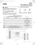
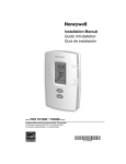
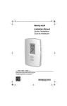
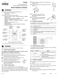
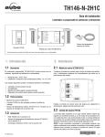
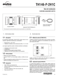
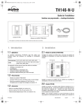
T6811DP08/T6812DP08 Digital Thermostat INSTALLATION INSTRUCTIONS INSTALLATION GUIDE CAUTION Electrical Hazard. Can cause electrical shock or equipment damage. Disconnect power before installation. UP BUTTON DOWN BUTTON FAN SWITCH MODE BUTTON POWER SWITCH Terminal Designations Terminal MCR29502 Display INDICATES THE INSTALLER SETUP INDICATES THE NUMBER OF SETUP OR TEST INDICATES THE INSTALLER TEST KEYPAD LOCK INDICATES THE SETPOINT Lock Setup Set to Test Designation L Line Voltage Power Ch/Cc Heating close/Cooling close W/Y Heating open/Cooling open N Line Voltage Ground Gl Low speed fan Gm Medium speed fan Gh High speed fan Wiring Diagrams INDICATES THE TEMPERATURE L L CURRENT MODE Ch/Cc INDICATES TEMPERATURE IS “CALLING” FOR HEAT OR COOL M29503 W/Y VALVE N N GI Gm FAN Gh M29504 Fig. 1. Typical wiring for ON/OFF control in 2 pipes Heat/ Cool/1H1C (for 2-wire valve actuators). 62-0325ES-01 T6811DP08/T6812DP08 DIGITAL THERMOSTAT L L Ch/Cc W/Y VALVE N N GI Gm M29506 FAN Fig. 3. Wiring thermostat. Gh M29505 Fig. 2. Typical wiring for ON/OFF control in 2 pipes Heat/ Cool/1H1C (for 3-wire valve actuators). Installation 1. 2. 3. 4. 5. Align the top of the thermostat with the back cover and push down on the back cover. See Fig. 4, left. Insert the locking screw into the whole on the bottom of the thermostat and tighten. See Fig. 4, right. Pull the wires through the wire hole on the wallplate and place the back cover over the junction box. Insert the mounting screws and tighten. See Fig. 3, left. Loosen screw terminals used for the application. Insert the wires into the terminal block and tighten each screw terminal. See Fig. 3, right. M29507 Fig. 4. Installing thermostat. 62-0325ES—01 2 T6811DP08/T6812DP08 DIGITAL THERMOSTAT Installer Setup 1. 2. 3. 4. No. 1 Press and hold UP and MODE buttons simultaneously for 3 seconds to enter the Installer Setup mode. Press UP or DOWN button to change settings. Press MODE button to advance to the next function. Press and hold UP and MODE buttons simultaneously for 3 seconds to exit and save settings. Description System Type Possible Options 0 Heat only 1 Cool only 2 Two pipes 1H1C manual (Default) 9 Temperature Scale 1–12 4 (Default) 14 CPH value For Cool 1–6 3 (Default) 18 Display Temperature -2°C (-4°F) adjustment -1.5°C (-3°F) Possible Options 0 Heat Off 30 Installer Test Cool 0 Cool Off 70 Press UP button to see software info (71, 72 & 73) 71 Software version (Major) 72 Software version (Minor) 73 Identification code 1 Heat On 1 Cool On 1. Power On/Off Slide the POWER switch thermostat will enter the On/Off mode. 0 °C (Default) CPH value For Heat Description Installer Test Heat Operating Your Thermostat 0 °F 13 No. 10 2. Fan Switch Slide the FAN switch to select Fan mode High. Low, Med, 3. System Mode Setting Press the MODE button to choose Heat, Cool or Vent. In ventilation mode, only the fan will operate. -1°C (-2°F) -0.5°C (-1°F) 0°C (0°F) (Default) 4. Temperature Setting In Heat/Cool mode, press the or (UP or DOWN button) to select the desired temperature setting. 0.5°C (1°F) 1°C (2°F) 1.5°C (3°F) Table 1. Troubleshoting Tips. 2°C (4°F) 19 Temperature Display 0 Display Room mode Temperature (Default) If... 1 Display Setpoint 20 Heating Range Stops 10–32°C Default 32°C (50–90°F) Default 90°F 21 Cooling Range Stops 10–32°C Default 10°C (50–90°F) Default 50°F 22 Keypad Lockout Installer Test 1. 2. 3. 4. Heating system does not turn on • Set the mode to Heat by pressing the Mode button. • Check that the heat temperature setting is above the room temperature. • Check heating on icon shows solidly in the display. • Wait five mintues for the heating system to respond. Cooling system does not turn on. • Set the mode to Cool by pressing the Mode button. • Check that the cool temperature setting is below the room temperature. • Check cooling on icon shows solidly in the display. • Wait five mintues for the cooling system to respond. 0 All keys available (Default) 1 All keys locked out Press and hold UP and DOWN buttons simultaneously for 3 seconds to enter the Installer Test mode. Press UP or DOWN button to change settings. Press MODE button to advance to the next function. Press and hold UP and MODE buttons simultaneously for 3 seconds to exit and save settings. The Mode • Check whether the keypad is locked or button doesn’t not. work. • Check whether the thermostat is off. The Up or Down button doesn’t work. 3 Then... • Check whether the keypad is locked or not. • Check whether the system is working Ventilation mode. • Check whether the thermostat is off. 62-0325ES—01 T6811DP08/T6812DP08 DIGITAL THERMOSTAT Automation and Control Solutions Honeywell International Inc. Honeywell Limited-Honeywell Limitée 1985 Douglas Drive North 35 Dynamic Drive Golden Valley, MN 55422 Toronto, Ontario M1V 4Z9 customer.honeywell.com ® U.S. Registered Trademark © 2009 Honeywell International Inc. 62-0325ES—01 M.S. 10-09 Termostato Digital T6811DP08/T6812DP08 INSTRUCCIONES DE INSTALACIÓN Designación de terminales Terminal Descripción L BOTÓN ARRIBA BOTÓN DE MODO BOTÓN ABAJO CONMUTADOR DEL VENTILADOR CONMUTADOR DE ENCENDIDO MSCR29502 Pantalla INDICA EL NÚMERO DE AJUSTE O DE TEST INDICA EL TEST DEL INSTALADOR INDICA EL PUNTO DE AJUSTE Ch/Cc Calor cerrado/frío cerrado W/Y Calor abierto/frío abierto N Voltaje de línea a tierra Gl Velocidad baja del ventilador Gm Velocidad media del ventilador Gh Velocidad alta del ventilador Diagrama de cableado INDICA LA CONFIGURACIÓN DEL INSTALADOR BLOQUEO DE TECLADO Voltaje de línea L L Ch/Cc Lock Setup Set to Test W/Y VÁLVULA N N GI INDICA LA TEMPERATURA Gm VENTILADOR Gh MODO ACTUAL MS29504 INDICA SI LA TEMPERATURA ESTÁ EN FRÍO O EN CALOR MS29503 Fig. 1. Cableado de control típico para prendido/apagado en dos tubos Calor/frío/1H1C (para activadores de válvula de 2 cables). GUÍA DE INSTALACIÓN PRECAUCIÓN RIESGO ELECTRICO. Qué puede causar un corto eléctrico o daño al equipo. Desconecte la energía antes de la instalación y de la reparación. 62-0325ES-01 TERMOSTATO DIGITAL T6811DP08/T6812DP08 L L Ch/Cc W/Y VÁLVULA N N GI Gm M29506 VENTILADOR Fig. 3. Cableado del termostato. Gh MS29505 Fig. 2. Cableado de control típico para prendido/apagado en dos tubos Calor/frío/1H1C (para activadores de válvula de 3 cables). Instalación de termostato 1. 2. 3. 4. 5. Alinee la parte superior del termóstato con la tapa posterior y empuje la tapa posterior hacia abajo. Consulte la Fig. 4 a la izquierda. Inserte el tornillo de bloqueo en el agujero de la parte inferior del termostato y apriete. Consulte la Fig. 4 a la derecha. Pase los cables a través del agujero para cables de la placa de pared y coloque la tapa posterior sobre la caja de empalme. Inserte los tornillos de montaje y apriete. Consulte la Fig. 3 a la izquierda. Suelte los terminales de tornillo utilizados para la aplicación. Inserte los cables en el bloque de terminales y apriete cada terminal de tornillo. Consulte la Fig. 3 a la derecha. M29507 Fig. 4. Instalación del termostato. 62-0325ES—01 2 TERMOSTATO DIGITAL T6811DP08/T6812DP08 Configuración del instalador 1. 2. 3. 4. No. 1 Prueba del instalador Mantenga presionados simultáneamente los botones UP (ARRIBA) y MODE (MODO) durante 3 segundos para ingresar al modo Configuración del instalador. Presione el botón UP (ARRIBA) o DOWN (ABAJO) para cambiar los ajustes. Presione el botón MODE (MODO) para avanzar a la función siguiente. Mantenga presionados simultáneamente los botones UP (ARRIBA) y MODE (MODO) durante 3 segundos para salir y guardar los ajustes. Descripción Tipo de Sistema 1. 2. 3. 4. No Opciones 0 Solamente calor 10 Mantenga presionados simultáneamente los botones UP (ARRIBA) y DOWN (ABAJO) durante 3 segundos para ingresar al modo Prueba del instalador. Presione el botón UP (ARRIBA) o DOWN (ABAJO) para cambiar los ajustes. Presione el botón MODE (MODO) para avanzar a la función siguiente. Mantenga presionados simultáneamente los botones UP (ARRIBA) y MODE (MODO) durante 3 segundos para salir y guardar los ajustes. Descripción Prueba del instalador, calor 1 Solamente frío 9 Escala de temperatura Posibles opciones 0 calor apagado 1 calor encendido 2 Dos tubos 1C1H manual (Prestablecido de fabrica) 30 0 °F 70 Presione el botón UP (ARRIBA) para ver información de software (71, 72 y 73) 71 Versión de software (principal) 72 Versión de software (secundaria) 73 Código de identificación Valor CPH para calor 1–12 4 (Prestablecido de fabrica) 14 Valor CPH para frío 18 Pantalla de ajuste de -2°C (-4°F) temperatura -1.5°C (-3°F) 0 frío apagado 1 frío encendido 0 °C (Prestablecido de fabrica) 13 Prueba del instalador, frío 1–6 3 (Prestablecido de fabrica) Uso del termostato 1. Prendido/apagado Deslice el botón del ventilador para ingresar al modo prendido/apagado. -1°C (-2°F) -0.5°C (-1°F) 2. Botón del ventilador Deslice el botón del ventilador para ingresar al modo (Bajo), Med (Medio), High (Alto). 0°C (0°F) (Prestablecido de fabrica) 0.5°C (1°F) Low 3. Configuración del modo del sistema Presione el botón de Modo para escoger Heat (calor), Cool (frío) o Vent (vent). En el modo de ventilación sólo funcionará el ventilador. 1°C (2°F) 1.5°C (3°F) 2°C (4°F) 19 Pantalla de modo de 0 Pantalla de temperatura de temperatura la habitación (Prestablecido de fabrica) 20 Rango de detención de calor 10–32°C Prestablecido de fabrica 32°C (50–90°F) Prestablecido de fabrica 90°F 21 Rango de detención de frío 10–32°C Prestablecido de fabrica 10°C (50–90°F) Prestablecido de fabrica 50°F 22 Bloqueo del teclado 0 Todas las teclas disponibles (Prestablecido de fabrica) 1 Pantalla de setpoint 4. Ajuste de temperatura En modo de calor/frío, presione o (arriba o abajo) para seleccionar la temperatura deseada. 1 Todas las teclas bloqueadas 3 62-0325ES—01 TERMOSTATO DIGITAL T6811DP08/T6812DP08 Tabla 1. Tips para solución de problemas. Si... El sistema de calor no se inicia. Entonces... • Seleccione el modo en Heat (calor) presionando el botón de modo. • Verifique si la temperatura del cuarto está por encima del setpoint. • Verifique si el icono de calor se encuentra sólido en la pantalla. • Espere cinco minutos para que el sistema de calor responda. (frío) El sistema de • Seleccione el modo en Cool presionando el botón de modo. enfriamiento no • Verifique si la temperatura del cuarto está se inicia. por debajo del setpoint. • Verifique si el icono de frío se encuentra sólido en la pantalla. • Espere cinco minutos para que el sistema de enfriamiento responda. El botón de modo no responde. • Verifique si el teclado se encuentra o no bloqueado. • Verifique si el termostato está apagado. Los botones • Verifique si el teclado se encuentra o no arriba/abajo no bloqueado. funcionan • Verifique si el sistema está trabajando en modo de ventilación. • Verifique si el termostato está apagado. Soluciones de automatización y control Honeywell International Inc. Honeywell Limited-Honeywell Limitée 1985 Douglas Drive North 35, Dynamic Drive Golden Valley, MN 55422 Toronto, Ontario M1V 4Z9 customer.honeywell.com ® Marca Registrada en los E.U.A © 2009 Honeywell International Inc. todos Los Derechos Reservados 62-0325ES—01 M.S. 10-09