1
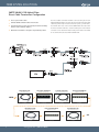
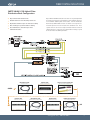
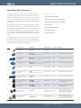
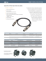
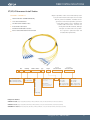
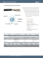
FIBER SYSTEM SOLUTIONS
PRODUCT GUIDE
FIBER SYSTEM SOLUTIONS
TABLE OF CONTENTS
INTRODUCTION
page (2-3)
SYSTEM CONFIGURATION & FLOW
page (4-5)
HYBRID FIBER CABLE ASSEMBLIES
page (6-9)
DISTRIBUTION RACKS
page (10-11)
BREAKOUT BOXES
page (12-13)
DISTRIBUTION RACK ACCESSORIES & PARTS
page (14)
CLEANING TOOLS & INSTRUCTIONS
page (15)
PANELS
page (16-19)
LEMO CONNECTORS
page (20)
CANARE CONNECTORS
page (21)
DUSTCAPS, BOOTS & INSTALLATION TOOLS
page (22)
PANEL MOUNT FIBER CONNECTORS
page (23)
TAC-4 & TAC-12 CABLE ASSEMBLIES
page (24)
OPTICALCON® FIBER OPTIC CABLE ASSEMBLIES
page (25)
ST/SC/LC CABLE ASSEMBLIES
page (26-29)
9.2MM HYBRID FIBER OPTIC CABLE
page (30-31)
12MM HYRID FIBER OPTIC CABLE
page (32)
16MM HYBRID FIBER OPTIC CABLE
page (33)
HD CAMERA ELECTRICAL CABLE
page (34)
THREE-CHANNEL FIBER CABLE
page (35)
SINGLE-MODE OPTICAL FIBER CABLE
page (36)
MULTI-MODE OPTICAL FIBER CABLE
page (36)
TACTICAL OPTICAL FIBER CABLE
page (37-38)
INDEX
page (39)
OPTICAL FIBER
SYSTEM SOLUTIONS
CABLE ASSEMBLIES | DISTRIBUTION SYSTEMS | REPAIRS | CABLE & CONNECTORS
T
he leading innovator of interconnect technology for broadcast and pro A/V applications, Gepco delivers a full line of optical fiber solutions for high definition audio
and video applications. Engineered and manufactured to industry leading stan-
dards, Gepco fiber systems bring the optical clarity and reliability required for highbandwidth data transmission in television, video production,
staging, outdoor broadcast and professional audio applications. With a complete range of cable assemblies, panels, components and accessories, Gepco’s optical fiber
systems product line provides a turn-key optical solution.
Broadcast and Pro A/V
Hybrid SMPTE HD Cameras
Tactical Applications
Distribution Systems
Components
Test Equipment and Accessories
FIBER SYSTEM SOLUTIONS
SMPTE 304M/311M Hybrid Fiber
Direct Cable Termination Configuration
Lowest System Attenuation
The Direct Cable termination method is achieved with panel mount
SMPTE 304M hybrid fiber connectors directly terminated onto the hybrid
cable that permanently interconnects between panels, junction boxes,
and control room racks. Panel mount SMPTE 304M connectors offer
the lowest overall insertion-loss at each breakout point. Panel Mount
connector must be field terminated or factory terminated and installed
on-site with the DCS.3K.175.72LN installation tool.
Utilized SMPTE 304M Panel Mount Connectors
Field Terminated or Factory Terminated (If Installed with Body
Removal and Installation Adapter)
Blank Panels Available in Straight or Angled Configurations
Hybrid Cable Assembly
from Camera to Panel
Socket and Plug Assembly
Panel Loaded with Bulkheads
at Studio or Camera Location
+
CAMERA
See Page 6
See Page 16
Hybrid Cable Assembly
for Patching Between Panels
Panel Loaded with Bulkheads
at Machine Room Location
Interconnects Between Blank Panels
+
See Page 7
Panel Loaded with Bulkheads
at Machine Room Location
See Page 16
Plug Bulkhead Assembly
Interconnect from Panel to CCU
CCU
See Page 6
4
www.gepco.com | 800.966.0069
See Page 16
See Page 7
FIBER SYSTEM SOLUTIONS
SMPTE 304M/311M Hybrid Fiber
Distribution Rack Configuration
Easy to Field-install and Terminate
Gepco HDR and HDRA distribution racks offer an exceptionally flexible
and modular solution to the field deployment and installation of permanent installation SMPTE hybrid camera cables. With the Distribution
Rack method, SMPTE 304M connectors are broken out to separate electrical and optical elements on the back of the distribution rack. These
separate elements can then be readily terminated to fiber and electrical
cabling without the need for the specialized labor or tooling required
for the termination of SMPTE hybrid fiber.
Modular Channels can be Reconfigured On-site
Replaceable Contact Jumpers for Field Serviceability
Does not Require Specialized Labor or Tooling
Uses Cost Effective, General Purpose Fiber
and Electrical Cables
Hybrid Cable Assembly
from Camera to Panel
at Studio or Camera Location
Distribution Rack
Single-mode Fiber & Electrical Cable
See Page 6
See Page 10
See Pages 34 & 36
Interconnects Between Distribution Racks
CAMERA
Distribution Rack
at Machine Room Location
Hybrid Cable Assembly
for Patching Betwween Distribution Racks
Distribution Rack
at Machine Room Location
Hybrid Component Breakout
Interconnects Back of HDR to CCU
CCU
See Page 10
See Page 6
See Page 10
See Page 8
www.gepco.com | 800.966.0069
5
FIBER SYSTEM SOLUTIONS
SMPTE 304M/311M Hybrid Fiber Cable Assemblies
Gepco GHF hybrid fiber and copper camera cables, terminated with
SMPTE 304M connectors for high definition video camera to CCU interconnects.
Gepco SMPTE hybrid fiber cables utilize two single-mode fibers for high
bit-rate signal transmission and copper elements for auxiliary and signal electrical connections. Each fiber is coated with a high tensile
strength coating for exceptional durability and strength. The copper
elements feature a heat resistant PE insulation material for dependable
performance in high temperature environments.
Fiber contacts are machine polished to meet or exceed all SMPTE standards. With typical UPC performance of -55dB RL, Gepco hybrid fiber
cables achieve exceptional optical clarity to deliver reliable performance and low transmission loss.
F E AT U R E S & B E N E F I T S
Machine Polished
-55dB Return Loss (Typical)
Portable, Extra-rugged, and Permanent Install Versions
Lemo or Canare Connectors
Extra-rugged Designs
Heat Resistant
Meets or Exceeds SMPTE 304M/311M Standards
Portable: Heavy-duty 12mm Type
Cable Type
HDC120P
Options
Lemo or Canare Connectors
Connector Type
SMPTE 304M Hybrid Connectors - 1 Plug,
1 Socket with Metal Dust Caps
Standard Lengths
50’, 100’, 164’, 250’, 328’, 500’, 656’
PART NUMBER: GHF12B-0-(length)
Portable: Thin Profile 9.2mm Type
Cable Type
HDC920
Options
Lemo or Canare Connectors
Connector Type
SMPTE 304M Hybrid Connectors - 1 Plug,
1 Socket with Metal Dust Caps
Overbody Rubber Boot
Standard Lengths
50’, 100’, 164’, 250’, 328’, 500’, 656’
(One end shown with optional overbody
boot. Please specify when ordering.)
6
PART NUMBER: GHF92A-0-(length)
www.gepco.com | 800.966.0069
-OB
Add for Overbody Boot Option
FIBER SYSTEM SOLUTIONS
SMPTE 304M/311M Hybrid Fiber Cable Assemblies
Standard In-line: Permanent Installation
Cable Type
HDC920R
Options
Lemo or Canare Connectors
Connector Type
SMPTE 304M Hybrid Connectors - 1 Plug,
1 Socket with Metal Dust Caps
Standard Lengths
50’, 100’, 164’, 250’, 328’, 500’, 656’
PART NUMBER: GHF92B-0-(length)
Plug Bulkhead: Permanent Installation
Cable Type
HDC920R
Options
Lemo or Canare Connectors
Connector Type
SMPTE 304M Hybrid Connectors - 1 Plug Bulkhead, 1 Socket with Metal Dust Caps
Standard Lengths
50’, 100’, 164’, 250’, 328’, 500’, 656’
PART NUMBER: GHF92B-0-(length)-PB
Socket Bulkhead: Permanent Installation
Cable Type
HDC920R
Options
Lemo or Canare Connectors
Connector Type
SMPTE 304M Hybrid Connectors - 1 Plug,
1 Socket Bulkhead with Metal Dust Caps
Standard Lengths
50’, 100’, 164’, 250’, 328’, 500’, 656’
PART NUMBER: GHF92B-0-(length)-SB
Plug & Socket Bulkhead: Permanent Installation
Cable Type
HDC920R
Options
Lemo or Canare Connectors
Connector Type
SMPTE 304M Hybrid Connectors - 1 Plug Bulkhead, 1 Socket Bulkhead with Metal Dust Caps
Standard Lengths
50’, 100’, 164’, 250’, 328’, 500’, 656’
PART NUMBER: GHF92B-0-(length)-SPB
www.gepco.com | 800.966.0069
7
FIBER SYSTEM SOLUTIONS
Hybrid Fiber Breakout: In-line Cable
F E AT U R E S & B E N E F I T S
Gepco hybrid fiber breakout cables offer an in-line solution
for breaking out SMPTE 304M Hybrid connectors to separate optical and electrical connectors. This solution
allows for the interfacing of SMPTE hybrid camera
devices, such as CCUs, directly to the back of a
Gepco HDR/HDRA distribution rack.
ST/SC/LC Optical Breakout
AMP Electrical Breakout
Machine Polished to -55dB RL (Typical)
CMR Rated 311M Hybrid Cable for Permanent
Installation
As with all Gepco GHF cables, the breakout
series is machine polished to meet or exceed all SMPTE 304M/311M standards.
Terminated with HDC920R riser rated
9.2mm cable, breakout cables can be
used in most permanent installation environments.
Available in Short or Long Cable Lengths
For Interfacing SMPTE Hybrid Devices with the Back Panel of
Distribution Panels or Other Component Level Devices
(First End)
Connector Format
Length
-
GHF92B
-
In Feet
(Second End)
Fiber Breakout
(Second End)
Electrical Breakout
/
P = Plug
ST = ST UPC
PB = Bulkhead Plug
SC = SC UPC
Standard Gender
A = 5-pin AMP Metal CPC (for Mating with HDR & HDRA Racks)
S = Socket
LC = LC UPC
B = 8-pin AMP CPC
SB = Bulkhead Socket
DSC = Duplex SC UPC
C = 6-pin AMP MATE-N-LOCK Cap
DLC = Duplex LC UPC
D = Blunt
Reverse Gender
E = 5-pin Reverse Gender CPC - In-line or Panel Mount
F = 8-pin Reverse Gender CPC - In-line
G = 8-pin Reverse Gender CPC - Panel Mount
H = 6-pin Reverse Gender MATE-N-LOCK
Fiber Connector Options
ST
SC
LC
Electrical Connector Options
A
B
C
Standard Gender
8
E
F
G
Reverse Gender
www.gepco.com | 800.966.0069
H
FIBER SYSTEM SOLUTIONS
Hybrid Fiber Breakout: Internal Distribution
F E AT U R E S & B E N E F I T S
Hybrid Fiber internal distribution cables do not use conventional hybrid 311M cables and are intended for internal
equipment or panel wiring only. The SMPTE 304M
end uses OEM style, non-cable-mount hybrid connectors and is terminated to insulated copper wire
and individual, simplex breakout fibers. The
component breakout end has ST, SC, or LC
optical connectors, while the copper elements feature AMP or blunt ends.
ST/SC/LC Optical Breakout
AMP Electrical Breakout
Machine Polished to -55dB RL (Typical)
Uses Short Length Fiber and Electrical Elements
For Panel Mounting in Blank Panels or as a Replacement
in Hybrid Devices
As with all Gepco GHF cables, the breakout series is machine polished to meet or
exceed all SMPTE 304M/311M standards.
(First End)
Connector Format
Length
-
GHFBK
-
In Feet
(Second End)
Fiber Breakout
(Second End)
Electrical Breakout
/
PB = Bulkhead Plug
ST = ST UPC
SB = Bulkhead Socket
SC = SC UPC
Standard Gender
A = 5-pin AMP Metal CPC (for mating with HDR & HDRA Racks)
LC = LC UPC
B = 8-pin AMP CPC
DSC = Duplex SC UPC
C = 6-pin AMP MATE-N-LOCK Cap
DLC = Duplex LC UPC
D = Blunt
Reverse Gender
E = 5-pin Reverse Gender CPC - Inline or Panel Mount
F = 8-pin Reverse Gender CPC - Inline
G = 8-pin Reverse Gender CPC - Panel Mount
H = 6-pin Reverse Gender MATE-N-LOCK
Fiber Connector Options
ST
SC
LC
Electrical Connector Options
A
B
Standard Gender
C
E
F
G
H
Reverse Gender
www.gepco.com | 800.966.0069
9
FIBER SYSTEM SOLUTIONS
Hybrid Fiber Distribution Racks
The HDR system of hybrid fiber distribution
racks distributes the
electrical and fiber
components of the
SMPTE hybrid connectors over separate optical and electrical
components allowing
for simplified in-wall installation. The discrete
optical and electrical elements between boxes
can now be interconnected with conventional distribution-type fiber and
Gepco's HDP electrical cable, thereby eliminating the need for specialized on-site hybrid fiber termination.
F E AT U R E S & B E N E F I T S
In addition, the HDR system offers improved field serviceability. The
internal fiber jumpers can be easily replaced when damaged or worn,
eliminating the costly need to completely replace the SMPTE hybrid connectors. The HDR chassis is constructed from rugged, powder-coated
steel, all optical components feature machine-polished ceramic ferrules
with ceramic sleeves, and the electrical connectors are rugged, metalshell CPC types.
Breaks Out Lemo HD Camera Connectors to Discrete
Electrical & Fiber Connectors
Machine-polished Optical Contacts & Ceramic Sleeves
Easy to Field Install
Replaceable Fiber Jumpers
Expandable up to Six Channels
1RU Chassis or 2RU Angeled Chassis Versions
Assemblies & Specifications
Part #
# of
Channels
Connectors
Dimensions
Chassis
Material/Color
Optical
Specifications
Steel/Black
Single-mode Optical Fiber, 8.3µ Mode Field,
125µ Cladding Diameter
Comments
Hybrid Fiber Distribution Rack
SMPTE 304M Connector to ST and Electrical Breakout
HDR-#x
or
HDRA-#x
1, 2, 3, 4,
5, or 6
Front:
SMPTE 304M Hybrid Fiber
Connectors with Metal Dust
Caps (1 per channel)
Straight:
1.75” High
(1RU)
x 19” Wide
x 3” Deep
Rear:
ST Female Metal Barrels
(Ceramic Sleeve) Internally
Coupled to Metal Body ST
Connectors (2 per channel)
AMP Metal-shell 5-pin CPC
Receptacle (1 per channel)
Part # Code
Angled:
3.5” High
(2 RU)
x 19” Wide
x 3 ¾” Deep
>45dB @ 1310nm Return Loss Hybrid
Contacts (Machine-polished)
Angled Front Panel
SMPTE 304M Compliant
<0.50 dB @ 1310nm Total Insertion Loss
per Fiber Element
x = Gender of Hybrid Fiber Connectors (P = Plug, S = Socket)
# = Number of Channels
Rear Panel Breakout per Channel
AMP 5-pin: Front View
1
AMP 5-pin Electrical Pinout
Pin 1 = Gray signal conductor (low voltage)
Pin 2 = Red signal conductor (low voltage)
Pin 3 = White auxiliary conductor (high voltage)
Pin 4 = Black auxiliary conductor (high voltage)
Pin 5 = Ground
2
3
4
5
10
>45dB @ 1310nm Return Loss ST Contacts
(PC Machine-polished)
ST Fiber Code
Fiber A = Top blue fiber in hybrid connector
Fiber B = Lower yellow fiber in hybrid connector
www.gepco.com | 800.966.0069
Lemo F2 fiber contacts in the
hybrid connectors break out
to two female ST connectors
per channel. Auxiliary contacts, signal contacts and
ground break out to the five
contacts in the CPC connector.
One, two and three channel
versions can be expanded to
four.
FIBER SYSTEM SOLUTIONS
Hybrid Fiber Distribution Racks
HDR-4S Front View and HDR-4(P or S) Rear View
Front
Rear
HDR-6P Front View and HDR-6(P or S) Rear View
Front
Rear
HDRA-4S Front View and HDRA-4(P or S) Rear View
Front
Rear
HDRA-6P Front View and HDRA-6(P or S) Rear View
Front
Rear
www.gepco.com | 800.966.0069
11
FIBER SYSTEM SOLUTIONS
Hybrid Fiber Breakout Boxes
The HBB series of portable SMPTE 304M boxes
breaks out the hybrid camera connector to two ST female connectors
on
a
recessed,
protective metal top-plate with
optional electrical connectors.
The breakout of the hybrid connector to discrete, industry-standard optical and electrical
components allows for an HD
camera to CCU interconnection
over existing fiber tie-lines in facilities
where hybrid fiber interconnects may
not be present.
All optical components feature machine-polished ceramic ferrules and
ceramic sleeves for superior optical alignment and low loss. The chassis is constructed from heavy-gage anodized aluminum for use in remote production environments. In addition to the standard
configuration, the HBB breakout box is also available with XLR or 5-pin
AMP connectors that are hard wired to the power and/or signal components of the SMPTE hybrid connectors.
F E AT U R E S & B E N E F I T S
Breaks Out SMPTE 304M Connector to Interface with Existing SM Fiber Tie-lines
Machine-polished Optical Contacts & Ceramic Sleeves
Replaceable Fiber Jumpers
Rugged Aluminum Chassis
Optional XLR or 5-pin AMP Connectors
Includes Metal Dust Caps
Assemblies & Specifications
Part #
# of
Channels
Connectors
Optional
Electrical Connector
Chassis
Dimensions
Chassis
Material
Optical
Specifications
(3) 5-pin Amp CPC
Connector
4.5” High x
5.25” Wide x
9” Long
1/8” Extruded
Aluminum
(Black Anodized)
Single-mode Optical Fiber, 8.3µ Mode Field,
125µ Cladding Diameter
Hybrid Fiber to ST Breakout Box
Three-channel, 9” Long Chassis
HBB903xy
3
(6) Female ST Barrels
with Dust Caps (Metal
Housing, Ceramic Sleeve)
Internally Coupled with
Metal Body ST Connectors
with Ceramic Ferrules
(3) Hybrid Fiber SMPTE
304M Connector (Plug
or Socket) with Metal
Dust Caps
-or-
>45dB @ 1310nm Return Loss ST Contacts
(PC Machine-polished)
(3) Male or
Female XLR
(Power elements
from fiber are not
terminated.)
>45dB @ 1310nm Return Loss Lemo F2
Contacts (Machine-polished)
<0.50dB @ 1310nm Total Insertion Loss
per Fiber Element
Also available without
electrical connectors.
SMPTE 304M Compliant
Hybrid Fiber to ST Breakout Box
Single-channel, Small Footprint Type
HBB901xy/4.5
1
(2) Female ST Barrels
with Dust Caps (Metal
Housing, Ceramic Sleeve)
Internally Coupled with
Metal Body ST Connectors
with Ceramic Ferrules
(1) Hybrid Fiber SMPTE
304M Connector (Plug
or Socket) with Metal
Dust Caps
(1) 5-pin Amp CPC
Connector
4.5” High x
5.25” Wide x
4.5” Long
-or(1) Male or
Female XLR
(Power elements
from fiber are not
terminated.)
Also available without
electrical connectors.
Part # Code
12
x = Gender of Lemo Connectors (P = Plug, S = Socket)
y = Gender of Electrical Connectors (XF = Female XLRs, XM = Male XLRs, A = Amp 5-pin CPC)
www.gepco.com | 800.966.0069
1/8” Extruded
Aluminum
(Black Anodized)
Single-mode Optical Fiber, 8.3µ Mode Field,
125µ Cladding Diameter
>45dB @ 1310nm Return Loss ST Contacts
(PC Machine-polished)
>45dB @ 1310nm Return Loss Lemo F2
Contacts (Machine-polished)
<0.50dB @ 1310nm Total Insertion Loss
per Fiber Element
SMPTE 304M Compliant
FIBER SYSTEM SOLUTIONS
Hybrid Fiber Breakout Boxes
HBB901 Top View
HBB903 Top View
HBB901 Side View
(SMPTE 304M Socket Side)
HBB903 Side View
(SMPTE 304M Plug Side)
HBB901 Side View
(Female XLR Side)
HBB903 Side View
(5-pin AMP CPC Side)
Side Panel Electrical Connector Options
AMP 5-pin: Front View
1
2
3
4
5
AMP 5-Pin
XLR Male
XLR Female
ST Fiber Code
Fiber A = Top blue fiber in hybrid connector
Fiber B = Lower yellow fiber in hybrid connector
AMP 5-pin Electrical Pinout (Optional)
Pin 1 = Gray signal conductor (low voltage)
Pin 2 = Red signal conductor (low voltage)
Pin 3 = White auxiliary conductor (high voltage)
Pin 4 = Black auxiliary conductor (high voltage)
Pin 5 = Ground
XLR Pinout (Optional)
Pin 1 = Ground
Pin 2 = Red signal conductor (low voltage)
Pin 3 = Gray signal conductor (low voltage)
Black & white power elements in hybrid fiber
connector are floated with no connector.
www.gepco.com | 800.966.0069
13
FIBER SYSTEM SOLUTIONS
Hybrid Fiber Rack Accessories & Parts
REPLACEMENT PARTS AND TOOLS
CABLE MOUNT ELECTRICAL CONNECTORS
14
Part Number
Description
HDR-JMP-F2/ST
Replacement F2 to ST Internal Jumper
AMP-66182-1
Replacement AMP Pins
AMP-305183
AMP Pin Extraction Tool
AMP-208719-1
Amp 5-pin Panel Mount Connector
Part Number
Description
AMP-208718-1
AMP 5-pin Cable Mount CPC Plug
AMP-208945-5
AMP CPC Metal Shell with Clamp
AMP-66183-1
Amp CPC Socket (for 26 - 20 AWG Wire)
AMP-66181-1
Amp CPC Socket (for 18 - 16 AWG Wire)
www.gepco.com | 800.966.0069
FIBER SYSTEM SOLUTIONS
Cleaning Tools & Instructions
ALIGNMENT REMOVAL TOOLS
CLEANING SWABS AND TOOLS
MICROSCOPE KITS
CABLE TESTER
Part Number
Description
DCS.F2.035.PN
Dual-ended Tool for Plug-end Alignment Sleeve Removal
of SMPTE 304M Connectors
DCS.91.F23.LA
Single-ended Tool for Plug-end Alignment Sleeve Removal
of SMPTE 304M Connectors with Cotton Swab Resevoir
Part Number
Description
Quantity per Package
WST.KI.125.34
Premoistened Cotton Swabs - Pack of 2
(One Dry, One Wet) for SMPTE 304M, ST,
SC, or LC Contacts
2
GEP-HFCS
Bag of 100 Cotton Swabs (Not Premoistened)
for SMPTE 304M, ST, SC, or LC Contacts
100
SCK-SC-250
Cleaning Tool for Female Panel Mount ST, SC
or Other 2.5mm Fiber Contacts
1 (525+ Cleaning Uses)
SCK-SC-125
Cleaning Tool for Female Panel Mount LC or Other
1.25mm Fiber Contacts
1 (525+ Cleaning Uses)
Part Number
Description
WST.CI.100.1A
Microscope Kit - Includes Scope, LCD Display, Positioner for F2 SMPTE 304M
Fiber Contacts, Positioner for 2.5mm Fiber Contacts, Battery and Charger,
DCS.F2.035.PN Extraction Tool, Carrying Case
WST.CI.201.1A
Includes all of the Components in the Standard WST.CI.100.1A Kit, Plus a Visual
Fault Finder with Tip, Launch Cable for Fault Finder, and 50 Premoistened Cotton
Swabs
Part Number
FCT-FCKIT
Description
Field Test Set for SMPTE 304M Hybrid Fiber Cables - Tests for Insertion and Return
Loss, and Electrical Continuity for Shorts/Opens - Does not Fault Locate Damage
www.gepco.com | 800.966.0069
15
FIBER SYSTEM SOLUTIONS
Hybrid Fiber Blank Panels
Gepco HBP panels offer a pre-engineered solution for the mounting of
SMPTE 304M hybrid fiber connectors in a 19” rack. Available in 1RU,
2RU, and angled 2RU versions, all panels feature Gepco’s unique Universal Punch Mount that allows for plug or socket connectors to be
mounted in any position. Each position also features a hole for mounting the dust cap lanyard eyelets directly to the panel.
F E AT U R E S & B E N E F I T S
1RU, 2U, or Angled 2RU Versions
Universal Punch Mount Accommodates Plug or Socket
Connectors (Does Not Accommodate PEW Connectors)
Works with Lemo or Canare Brand Connectors
The HBP panels are used in the Direct Cable Termination method (see
page four for system configuration details). When using HBP panels
with pre-terminated cable assemblies, the connector body of the cable
assembly can be removed, allowing for the assembly to be passed
through the panel hole punch from the rear and reassembled from the
front.
Additional Hole for Dust Cap Lanyard Mounting
Can Be Loaded with Pre-terminated Cable Assemblies
Angled 2RU Panel
PART NUMBER: HBPA-*U
* Designates Number of Holes (1-6)
Straight 2RU Panel
PART NUMBER: HBP2-*U
* Designates Number of Holes (1-6)
Straight 1RU Panel
PART NUMBER: HBP1-*U
* Designates Number of Holes (1-6)
Note: Custom panels are also available. Please contact Gepco for details.
Ideal for Use With Bulkhead or Breakout Hybrid Fiber Cable Assemblies:
Bulkhead Hybrid (See page 7)
16
In-line Breakout (See page 8)
www.gepco.com | 800.966.0069
Internal Breakout (See page 9)
FIBER SYSTEM SOLUTIONS
Modular Isolation Panel System
Gepco’s modular isolation panel system is designed to provide flexibility
and expansion capabilities for the mounting of hybrid fiber and triax
connectors in a 19-inch rack format. The all-metal HMPF frame provides seven positions for the connector module mounts and is angled
to reduce the bend radius and clearance required for the interfacing cables. Available in four types, the nonconductive plastic HMP modules
provide electrical isolation between connectors and are available in
SMPTE 304M, Kings Tri-Loc, Neutrik OpticalCon® and blank versions.
F E AT U R E S & B E N E F I T S
Modular Design
Electrically Isolates Connectors
Angled Front Reduces Cable Bend Radius
All-metal Frame
Nonconductive Plastic Modules
Available for SMPTE 304M, Kings Tri-Loc
and Neutrik OpticalCon® Connector Formats
Type
Part Number
Application
Material
Dimensions
Modular Frame
HMPF
Angled 2RU Frame
with Open Positions
for up to 7 Modules
Steel
2RU: 3.5"H x 19"W
SMPTE Universal Module
HMP-S
Universal Punch Plug
or Socket SMPTE 304M
Hybrid Fiber Connectors
Nonconductive
Plastic
2" x 2"
Triax Module
HMP-T
Triax Punch for Male
or Female Kings Brand
Triax Connectors
Nonconductive
Plastic
2" x 2"
Neutrik OpticalCon® Module
HMP-N
Punch for Neutrik
OpticalCon® Connector
Nonconductive
Plastic
2" x 2"
Blank Module
HMP-B
Blank Filler Module
Nonconductive
Plastic
2" x 2"
Ideal for Use With Bulkhead or Breakout Hybrid Fiber Cable Assemblies:
Bulkhead Hybrid (See page 7)
In-line Breakout (See page 8)
Internal Breakout (See page 9)
www.gepco.com | 800.966.0069
17
FIBER SYSTEM SOLUTIONS
Feedthrough Panels & Chassis
Gepco’s series of feedthrough panels provides a convenient, pre-engineered solution for bulkhead interfacing of general-purpose ST, SC or
LC optical fiber formats. Utilizing premium grade, zirconia sleeve connectors, Gepco feedthrough panels deliver precision optical alignment
and low insertion loss. Available in two configurations, the flanged
panel series provides extra rigidity to minimize panel flexing, while the
chassis series provides a complete rear enclosure for cable management.
F E AT U R E S & B E N E F I T S
Precision, Zirconia Sleeve Connectors
Available with ST, SC, or LC Format Connectors
Flanged Panel Series for Extra Rigidity
Chassis Series for Integrated Cable Management
Black Anodized and Engraved
Part Number
Connector Format
Number of Positions
Dimensions
Additional Features
FP1-xxST
FC1-xxST
Flat
Chassis
ST Feedthrough
6, 8, 10, or 12
1RU: 1.75"W x 19"H
1RU: 1.75"H x 19"W x 3"D
Zirconia Sleeve, Metal Dust Caps
FP1-xxSC
FC1-xxSC
Flat
Chassis
SC Feedthrough
6, 8, 10, or 12
1RU: 1.75"W x 19"H
1RU: 1.75"H x 19"W x 3"D
Zirconia Sleeve, Spring Loaded
Shutter
FP1-xxSCD
FC1-xxSCD
Flat
Chassis
SC Duplex Feedthrough
4, 6, or 8
1RU: 1.75"W x 19"H
1RU: 1.75"H x 19"W x 3"D
Zirconia Sleeve
FP1-xxLC
FC1-xxLC
Flat
Chassis
LC Feedthrough
6, 8, 10, or 12
1RU: 1.75"W x 19"H
1RU: 1.75"H x 19"W x 3"D
Zirconia Sleeve
Flat
Chassis
LC Duplex Feedthrough
6, 8, 10, or 12
1RU: 1.75"W x 19"H
1RU: 1.75"H x 19"W x 3"D
Zirconia Sleeve, Spring Loaded
Shutter
FP1-xxLCD
FC1-xxLCD
18
Panel Type
www.gepco.com | 800.966.0069
FIBER SYSTEM SOLUTIONS
Custom Panels
In addition to pre-engineered panels, chassis, and distribution systems,
Gepco can custom design and manufacture panels to custom installation requirements. Panels can be fabricated from aluminum, steel, or
stainless steel in a variety of colors, paint, or anodized finishes. Connector punches can be made for a complete range of broadcast and
professional A/V connector formats. Engraving, filling, and custom silkscreening options finish off the complete customized interface solution
for your venue or facility.
F E AT U R E S & B E N E F I T S
Completely Customized Panels
Aluminum, Steel or Stainless Steel
Wide Range of Connector Punches Available
Engraved, Filled or Silkscreened
Loaded with Connectors or Blank
Flat, Flanged, or Chassis Configurations
Connector Formats
ST Feedthrough
SC Feedthrough
LC Feedthrough
SMPTE 304M Plug Bulkhead
SMPTE 304M Socket Bulkhead
Neutrik OpticalCon®
TAC-4/12
BNC
Triax
Audio Connectors
Materials
Aluminum
Steel
Stainless Steel
Finishes
Annodized
Painted
Powder Coated
Engraved
Silk Screened
www.gepco.com | 800.966.0069
19
FIBER SYSTEM SOLUTIONS
Lemo Hybrid Fiber SMPTE 304M Connectors
The original and industry standard in SMPTE 304M connectors, Lemo
3K series connectors deliver the performance and dependability required in demanding broadcast and production applications. These
latest generation of Lemo 3K connectors feature an integrated cable
grip collet, braid crimp, and strength member anchor for exceptional
pull, bend, and strain relief. In addition, all exterior components are
now machined from stainless steel for superior hardness and corrosion
resistance. The F2 optical contacts deliver consistent end-face geometry
and long-term mating life.
F E AT U R E S & B E N E F I T S
Original and Industry Standard HDTV Camera
Connector
Stainless Steel Exterior Components
Integrated Collet, Crimp, and Anchor Strain Relief
System
Precision F2 Optical Contacts
In-line Cable Mount, Chassis Cable Mount, and Breakout
Versions
Meets or Exceeds SMPTE 304M Standards
Part Number
20
Configuration
Gender
Cable Type
Notes
FUW.3K.93C.TLMC96
Cable Mount
Plug
9.2mm
Heavy-duty Strain Relief & Stainless Steel Body
PUW.3K.93C.TLCC96
Cable Mount
Socket
9.2mm
Heavy-duty Strain Relief & Stainless Steel Body
FUW.3K.93C.TLMC12
Cable Mount
Plug
12mm
Heavy-duty 12mm Stainless Steel Body
PUW.3K.93C.TLCC12
Cable Mount
Socket
12mm
Heavy-duty 12mm Stainless Steel Body
FMW.3K.93C.TLMC96Z
Panel Mount
Plug
9.2mm
Square Flange with Mounting Holes, Stainless Steel
PBW.3K.93C.TLCC96Z
Panel Mount
Socket
9.2mm
Square Flange with Mounting Holes
PEW.3K.93C.TLCC96Z
Panel Mount
Socket
9.2mm
Round with Locking Ring, Stainless Steel
FXW.3K.93C.TLM
Panel Mount
Plug
Breakout
Not for Cable Mount, OEM Devices Only, Stainless Steel
EDW.3K.93C.TLC
Panel Mount
Socket
Breakout
Not for Cable Mount, OEM Devices Only, Stainless Steel
PSS.F2.BB2.LCE30
F2 Fiber Contact
Plug
9.2mm or 12mm
For Use with any Lemo SMPTE 304M Plug: Requires 2 per
Connector
FFS.F2.BB2.LCE30
F2 Fiber Contact
Socket
9.2mm or 12mm
For Use with any Lemo SMPTE 304M Socket: Requires
2 per Connector
www.gepco.com | 800.966.0069
FIBER SYSTEM SOLUTIONS
Canare Hybrid Fiber SMPTE 304M Connectors
Canare’s innovative SMPTE 304M connectors were designed for consistant performance, durability and simplified field cleaning. Canare
FC Hybrid Fiber connectors feature an integrated cable grip collet,
braid crimp, and strength member anchor for exceptional pull, bend,
and strain relief. All exterior components are made from high-polish,
nickel-plated brass for exceptional hardness and corrosion resistance.
The Canare optical contacts deliver consistent end-face geometry and
long-term mating life.
F E AT U R E S & B E N E F I T S
High-polish, Nickel-plated Brass Exterior Components
Unique, Easy-access End Face for Quick Cleaning
Integrated Collet, Crimp, and Anchor Strain Relief
System
Precision Optical Contacts
In-line Cable Mount, Chassis Cable Mount, and Breakout
Versions
Meets or Exceeds SMPTE 304M Standards
Part Number
Configuration
Gender
Cable Type
Notes
FCF
Cable Mount
Plug
9.2mm
Heavy-duty Strain Relief Design
FCM
Cable Mount
Socket
9.2mm
Heavy-duty Strain Relief Design
FCFRC
Panel Mount
Plug
9.2mm
Square Flange with Mounting Holes
FCMRC
Panel Mount
Socket
9.2mm
Square Flange with Mounting Holes
FCFR
Panel Mount
Plug
Breakout
Not for Cable Mount, OEM Devices Only
FCMR
Panel Mount
Socket
Breakout
Not for Cable Mount, OEM Devices Only
FCA120
Cable or Panel
Plug or Socket
12mm
Adapter for Terminating 9.2mm Connectors to 12mm
Cable
www.gepco.com | 800.966.0069
21
FIBER SYSTEM SOLUTIONS
SMPTE 304M Dust Caps, Boots & Installation Tools
These Gepco, Lemo, and Canare brand accessories provide additional
protection, weather resistance, and flex-relief to SMPTE 304M series hybrid fiber connectors. The stainless steel dust caps protect the end face
and optical fiber contacts from exterior contamination when the connector is unmated and not in use. They feature a heavy-gage, coated
lanyard chain to virtually eliminate breakage and fraying. Overbody
boots provide exceptional full-connector protection, while the standard
boot option provides additional flex relief to the connector and cable.
F E AT U R E S & B E N E F I T S
Stainless Steel Dust Caps with Heavy Duty Lanyard
Overbody Boots for Full Connector Protection
Standard Flex-relief Boots
Cable Pulling Adapter for Installing Pre-terminated Cables
Also available is the DCS series cable pulling adapter. This adapter
replaces the connector body during cable installation, allowing for a
pre-terminated hybrid fiber cable to be pulled in a permanent installation application.
Part Number
22
Description
Compatibility
HPDC
Stainless Steel Dust Cap
Cable Mount Plug, Lemo or Canare
HSDC
Stainless Steel Dust Cap
Cable Mount Socket, Lemo or Canare
HPDC-PM
Stainless Steel Dust Cap
Panel Mount Plug, Lemo or Canare
HSDC-PM
Stainless Steel Dust Cap
Panel Mount Socket, Lemo or Canare
GMF.3K.085.EANZ
Full Body Plug Boot
Lemo 9.2mm FUW Plug Cable Mount Connector
GMP.3K.085.EANZ
Full Body Socket Boot
Lemo 9.2mm PUW Cable Mount Socket Connector
DCS.3K.175.72LN
Cable Pulling Slug
Temporarly Replaces Body of Lemo FUW, PUW, FMW, PBW, or PEW
Connectors for Pulling Cable in a Permanent Installation
GMA.3B.090.DN
Bend Relief Boot 9.2mm
Lemo 9.2mm FGW, PHW, FMW, PBW, or PEW Connectors
(Not Compatible with Standard FUW and PUW Connectors)
GMA.4B.011.DN
Bend Relief Boot 12mm
Lemo 12mm FGW or PHW Connectors
(Not Compatible with Standard FUW and PUW Connectors)
CB29
Full Body Plug Boot
Canare FCM 9.2mm Socket Connector
CB30
Full Body Socket Boot
Canare FCF 9.2mm Plug Connector
www.gepco.com | 800.966.0069
FIBER SYSTEM SOLUTIONS
Panel Mount Fiber Connectors
Feedthrough, panel mount, fiber connectors provide precision alignment and mating between two cable mount connectors. With the exception of the TAC-4/12 types, these connectors do not contain a
ceramic ferrule or optical fiber elements. Terminated cables must be
mated to both sides of the panel mount feedthough to complete the interconnect.
F E AT U R E S & B E N E F I T S
Panel Mount Configurations
ST, SC, LC, and General-purpose Formats
Weather-tight Shuttered Versions Available
Zirconia Sleeves
General purpose, industry standard ST, SC, and LC formats are available in multiple configurations, including shuttered versions for the SC
and LC formats. Neutrik OpticalCon™ panel mount connectors use a
LC duplex format feedthough that is shuttered for contaminant protection. As with the standard LC feedthroughs, OpticalCon™ connectors
require a duplex LC connector to complete the interconnect and panel
wiring.
Precision Optical Allignment
Neutrik OpticalCon®
TAC-4/12 Connectors
The TAC-4/12 panel mount connectors utilize fiber termini that must
be bonded to the fiber and machine polished. The hermaphroditic design of the TAC-4/12 format permits the panel mount versions to be
mated to either end of a TAC4/12 cable assembly.
Connector Format
Part Number
Alignment Sleeve
Manufacturer Mating
ST Feedthrough
216-101-E
Zirconia (Ceramic)
Senko
Couples Two Male, Cable Mount STs
SC Feedthrough
277-101-1N
Zirconia (Ceramic)
222-101-1N (with Flange & Mounting Holes)
Senko
Couples Two Male, Cable Mount SCs
SC Feedthrough with
External Shutter
227-101-1E
222-101-1E (with Flange & Mounting Holes)
Zirconia (Ceramic)
Senko
Couples Two Male, Cable Mount SCs
SC Feedthrough - Duplex
227-201-1N
Zirconia (Ceramic)
222-201-1N (with Flange & Mounting Holes)
Senko
Couples Four Male, Cable Mount SCs
LC Feedthrough
999-111
Zirconia (Ceramic)
Senko
Couples Two Male, Cable Mount LCs
LC Feedthrough - Duplex
(SC Footprint)
999-411
999-311 (with Flange & Mounting Holes)
Zirconia (Ceramic)
Senko
Couples Four Male, Cable Mount LCs
LC Feedthrough - Duplex
(SC Footprint) with External Shutter
999-411-1E
999-311-1E (with Flange & Mounting Holes)
Zirconia (Ceramic)
Senko
Couples Four Male, Cable Mount LCs
OpticalCon™- Optalloy Finish
IP65 Waterproof
NO2-4FDW
NO2-4FDW-1 (with Ground Tab)
Zirconia (Ceramic)
Neutrik
Mates with In-line Neutrik OpticalCon™
or Standard Duplex LC
OpticalCon™- Ruthenium Finish
IP65 Waterproof
NO2-4FDW-R
NO2-4FDW-1-R (with Ground Tab)
Zirconia (Ceramic)
Neutrik
Mates with In-line Neutrik OpticalCon™
or Standard Duplex LC
Amphenol Four-channel
Tactical Connector
1098080-A1
Uses Fiber Termini, not
Amphenol
a Feedthrough Device
Must be terminated and machine
polished with 6 Amphenol M29504/14
Termini, and 6 Amphenol M29504/15
Termini. Termini are sold separately.
Amphenol Twelve-channel
Tactical Connector
FS12A8080X111F
Uses Fiber Termini, not
Amphenol
a Feedthrough Device
Must be terminated and machine
polished with 6 Amphenol M29504/14
Termini, and 6 Amphenol MIL29B1999C
Termini. Termini are sold separately.
www.gepco.com | 800.966.0069
23
FIBER SYSTEM SOLUTIONS
TAC-4 & TAC-12 Cable Assemblies
F E AT U R E S & B E N E F I T S
Factory Terminated in the USA
Machine Polished
4 or 12 Channels per Connector
Hermaphroditic Design Enables Mating to Cable
or Panel Mount Connectors in Either Direction
Extra-rugged Metal Shell
Dust Cap Included
TAC-4 and TAC-12 cable assemblies by Gepco are built for
the transmission of multiple optical fiber elements in hostile and portable applications. Each connector contains four or twelve elements in an extra-rugged,
hermaphroditic connector shell. The hermaphroditic design enables cables to be mated to either
TAC-4/12 panel connectors or other TAC4/12 cables in any direction providing flexibility for cable link expansion and
eliminating cables from being directionally
misdeployed. Machine polished and terminated in the US, Gepco TAC-4/12 cables have exceptionally low return-loss
and attenuation with consistent endface geometry. TAC-4/12 cables are
available in almost any length and
are custom terminated to user specifications.
Overall Specifications
Part #
# of Channels
GTS4-0-(length)
(4) Single-mode Fiber
Connectors
(2) Amphenol TAC-4,
SMPTE 358M
TAC-4 SMPTE 358M Hermaphroditc Assembly: Single-mode
Cable Type
Tactical, Polyurethane Jacket,
.220” Diameter
Available Lengths
50', 100', 164', 250',
328', 500', 656', or Custom
Color
Black Cable Jacket
Black Finish Connector Body
GTM4/50-0-(length)
(4) 50 µm Multi-mode Fiber
(2) Amphenol TAC-4,
Tactical, Polyurethane Jacket,
SMPTE 358M
.220” Diameter
TAC-4 SMPTE 358M Hermaphroditc Assembly: 50 µm Multi-mode
50', 100', 164', 250',
328', 500', 656', or Custom
Black Cable Jacket
Black Finish Connector Body
GTM4/62-0-(length)
(4) 62.5 µm Multi-mode Fiber
(2) Amphenol TAC-4,
Tactical, Polyurethane Jacket,
SMPTE 358M
.220” Diameter
TAC-4 SMPTE 358M Hermaphroditc Assembly: 62.5 µm Multi-mode
50', 100', 164', 250',
328', 500', 656', or Custom
Black Cable Jacket
Black Finish Connector Body
GTS12-0-(length)
(12) Single-mode Fiber
Tactical, Polyurethane Jacket,
.260” Diameter
50', 100', 164', 250',
328', 500', 656', or Custom
Black Cable Jacket
Gray Finish Connector Body
Tactical, Polyurethane Jacket,
.260” Diameter
50', 100', 164', 250',
328', 500', 656', or Custom
Black Cable Jacket
Gray Finish Connector Body
Tactical, Polyurethane Jacket,
.260” Diameter
50', 100', 164', 250',
328', 500', 656', or Custom
Black Cable Jacket
Gray Finish Connector Body
(2) Amphenol TAC-12
TAC-12 Hermaphroditc Assembly: Single-mode
GTM12/50-0-(length)
(12) 50 µm Multi-mode Fiber
(2) Amphenol TAC-12
TAC-12 Hermaphroditc Assembly: 50 µm Multi-mode
GTM12/62-0-(length)
(12) 62.5 µm Multi-mode Fiber
(2) Amphenol TAC-12
TAC-12 Hermaphroditc Assembly: 62.5 µm Multi-mode
Mechanical Performance Specifications
Operating Temperature
Minimum Bend Radius
-55°C to +85°C
1.8” (TAC-4), 2.1” (TAC-12)
Optical Performance Specifications
Fiber Type
8.3 µm Single-mode Fiber,
50 µm Multi-mode Fiber, or
62.5 µm Multi-mode Fiber
24
Cable Loss
Connector Loss
Connector Back Reflection
<.5dB
(per Connection)
-55dB RL (Typical),
-45dB RL (Max)
< 0.5dB/km @ 1310/1550nm (Single-mode)
< 3.5 dB/km @ 850nm (Multi-mode)
< 1dB/km @ 1300nm (Multi-mode)
www.gepco.com | 800.966.0069
FIBER SYSTEM SOLUTIONS
OpticalCon® Fiber Optic Cable Assemblies
F E AT U R E S & B E N E F I T S
Neutrik OpticalCon® cable assemblies by Gepco provide a
streamlined and ruggedized solution for the deployment
and interfacing of optical fiber in commercial and professional A/V applications. The OpticalCon® connector features a ruggedized body design, high
performance LC fiber contacts, and a unique
shutter mechanism to protect against damage
and contamination. Machine polished and
terminated in the US, OpticalCon® assemblies by Gepco provide exceptionally low
return-loss, attenuation, and consistent
end-face geometry. OpticalCon® assemblies are available in almost any
length and are custom terminated to
user specifications.
Factory Terminated in the US
Machine Polished
Two Fiber Channels per Connector
Industry Standard LC Fiber Contacts
Unique Shutter Mechanism Protects Contacts from Damage
and Contamination
-55dB Return Loss (Typical)
Ruggedized Body
Tactical Optical Fiber Cable
Overall Specifications
Part #
GNO2S-0-(length)
# of
Channels
Two Single-mode Fiber
Connectors
Cable Type
Available Lengths
Color
(2) Neutrik OpticalCon®, NO2SX
Tactical, Polyurethane Jacket,
5mm Diameter
50', 100', 164', 250',
328', 500', 656', or Custom
Black Cable Jacket
Nickle Finish Connector Body
Tactical, Polyurethane Jacket,
5mm Diameter
50', 100', 164', 250',
328', 500', 656', or Custom
Black Cable Jacket
Nickle Finish Connector Body
OpticalCon® Cable Assembly: SINGLE-MODE
GNO2M-0-(length)
Two Multi-mode Fiber
(2) Neutrik OpticalCon®, NO2MX
OpticalCon® Cable Assembly: MULTI-MODE
Mechanical Performance Specifications
Cable Retention Force
Lifetime
Insertion/Withdrawl Force
Operating Temperature
Minimum Bend Radius
500N
>1000 Cycles
<45N
-25°C to +75°C
4cm
Optical Performance Specifications
Type
Fiber Type
LC-UPC (Straight Polish)
9 µm Single-mode Fiber or
50 µm Multi-mode Fiber
Cable Loss
Connector Loss
Connector Back Reflection
<.5dB
(per Connection)
-55dB RL (Typical),
-45dB RL (Max)
< 0.5dB/km @ 1310/1550nm (Single-mode)
< 3dB/km @ 850nm (Multi-mode)
< 1dB/km @ 1300nm (Multi-mode)
* OpticalCon is a registered trademark of Neutrik AG All Rights Reserved
Also Available with Cable Reeler
Add reeler part number to suffix.
Standard configuration has cable mount
connector on both ends. Optional bulkhead
on reel is also available. Add “B” to end of
reeler suffix of part number.
GT310
GT380
GT520
www.gepco.com | 800.966.0069
25
FIBER SYSTEM SOLUTIONS
ST/SC/LC Tactical Snakes
F E AT U R E S & B E N E F I T S
Gepco’s tactical optical fiber snakes are terminated with
precision ST, SC, or LC format connectors to ruggedized,
optical fiber snake cable for use in hostile environments. Available with single-mode or multi-mode
optical fiber, tactical fiber cable assemblies come
in two construction types: distribution and
breakout. Distribution cables feature multiple
tight-buffered fibers and an overall armid
filler under a heavy-duty, polyurethane
master jacket. Breakout versions have individual armid fillers and PVC jackets for
each tight-buffered fiber, in addition to
the overall polyurethane master jacket,
to provide added protection. Precision
machine polished to UPC standards,
Gepco tactical fiber optic snakes deliver the performance required in
professional A/V and broadcast fiber
optic formats.
Machine Polished -55dB SRL UPC Quality
100% Tested and Verified
Low Attenuation and Return Loss
Precision Fiber Connectors
Distribution and Breakout Versions
Heavy-duty Polyurethane Master Jacket
Ruggedized, Tactical Grade, Internal Construction
Optional Overboot Protects Connector Fanout
Fiber
Number of Fibers
G
Type
-
T
S = Single-mode 9µ Fiber
M50 = Multi-mode 50µ Fiber
M62 = Multi-mode 62.5µ Fiber
02
04
06
08
10
12
18
24
D = Distribution
(First End)
Connector Format
Length
-
In Feet
(Tight Buffer Fiber with Overall Armid Filler)
(Second End)
Connector Format
/
ST = ST UPC
ST = ST UPC
SC = SC UPC
SC = SC UPC
LC = LC UPC
LC = LC UPC
B = Breakout
DSC = Duplex SC UPC
DSC = Duplex SC UPC
(Armid Filler and PVC Jacket
for Each Tight Buffer Fiber)
DLC = Duplex LC UPC
DLC = Duplex LC UPC
Example Part Numbers
GST02D-10-ST/ST (Single-mode 9µ Fiber, 2 Fibers, Distribution, 10 Feet, ST Connector First End, ST Connector Second End, No Boot Cover)
GST10B-25-SC/LC-B (Single-mode 9µ Fiber, 10 Fibers, Breakout, 25 Feet, SC Connector First End, LC Connector Second End, Overboot)
GM62T12D-12-LC/ST (Multi-mode 62.5µ Fiber, 12 Fibers, Distribution, 12 Feet, LC Connector First End, ST Connector Second End, No Boot Cover)
26
www.gepco.com | 800.966.0069
Overboot
-
(blank) = No Overboot
B = Overboot for Additional
Connector Protection
FIBER SYSTEM SOLUTIONS
ST/SC/LC Permanent Install Snakes
F E AT U R E S & B E N E F I T S
Gepco’s optical fiber snakes are terminated with precision
ST, SC, or LC format connectors to plenum or riser rated
cable for permanent installation. Available with single-mode or multi-mode optical fiber, permanent
install cable assemblies come in distribution and
breakout cable constructions. Precision machined polished to UPC standards, all Gepco
fiber optic assemblies deliver the performance required in professional A/V and
broadcast fiber optic formats.
Machine Polished -55dB SRL UPC Quality
100% Tested and Verified
Low Attenuation and Return Loss
Precision Fiber Connectors
Distribution and Breakout Versions
Plenum or Riser Rated for Permanent Install
Fiber
UL Rating
Number of Fibers
S = Single-mode 9µ Fiber
R = Riser Rated
M50 = Multi-mode 50µ Fiber
P = Plenum Rated
01
02
04
06
08
12
18
24
30
36
48
60
72 (Riser Only)
(First End)
Connector Format
Length
-
G
M62 = Multi-mode 62.5µ Fiber
Type
-
D = Distribution
(Second End)
Connector Format
/
In Feet
ST = ST UPC
ST = ST UPC
SC = SC UPC
SC = SC UPC
LC = LC UPC
LC = LC UPC
B = Breakout
DSC = Duplex SC UPC
DSC = Duplex SC UPC
(Armid Filler and PVC Jacket
for Each Tight Buffer Fiber)
DLC = Duplex LC UPC
DLC = Duplex LC UPC
(Tight Buffer Fiber with Overall Armid Filler)
Example Part Numbers
GSR02D-25-ST/ST (Single-mode 9µ Fiber, Riser Rated, 2 Fibers, Distribution, 25 Feet, ST Connector First End, ST Connector Second End)
GSP08B-50-SC/LC (Single-mode 9µ Fiber, Plenum Rated, 8 Fibers, Breakout, 50 Feet, SC Connector First End, LC Connector Second End)
GM62R12D-10-LC/ST (Multi-mode 62.5µ Fiber, Riser Rated, 12 Fibers, Distribution, 10 Feet, LC Connector First End, ST Connector Second End)
www.gepco.com | 800.966.0069
27
FIBER SYSTEM SOLUTIONS
ST/SC/LC Simplex Cables
F E AT U R E S & B E N E F I T S
Gepco’s optical fiber assemblies are terminated with precision ST, SC, or LC format connectors to plenum or riser
rated cable for permanent installation. Available with
single-mode or multi-mode optical fiber, simplex
cable assemblies are precision machined polished to UPC standards. All Gepco fiber optic
assemblies deliver the performance required
in professional A/V and broadcast fiber optic
formats.
Machine Polished -55dB SRL UPC Quality
100% Tested and Verified
Low Attenuation and Return Loss
Precision Fiber Connectors
Plenum or Riser Rated for Permanent Install
Fiber
UL Rating
G
(First End)
Connector Format
Length
01S
-
S = Single-mode 9µ Fiber
R = Riser Rated
M50 = Multi-mode 50µ Fiber
P = Plenum Rated
M62 = Multi-mode 62.5µ Fiber
-
In Feet
/
ST = ST UPC
ST = ST UPC
SC = SC UPC
SC = SC UPC
LC = LC UPC
LC = LC UPC
DSC = Duplex SC UPC
DSC = Duplex SC UPC
DLC = Duplex LC UPC
DLC = Duplex LC UPC
Example Part Numbers
GSR01S-25-ST/ST (Single-mode 9µ Fiber, Riser Rated, 25 Feet, ST Connector First End, ST Connector Second End)
GSP01S-50-SC/LC (Single-mode 9µ Fiber, Plenum Rated, 50 Feet, SC Connector First End, LC Connector Second End)
GM62R01S-10-LC/ST (Multi-mode 62.5µ Fiber, Riser Rated, 10 Feet, LC Connector First End, ST Connector Second End)
28
www.gepco.com | 800.966.0069
(Second End)
Connector Format
FIBER SYSTEM SOLUTIONS
ST/SC/LC Duplex Cables
F E AT U R E S & B E N E F I T S
Gepco’s optical fiber assemblies are terminated with precision ST, SC, or LC format connectors to plenum or riser
rated cable for permanent installation. Available with
single-mode or multi-mode optical fiber, duplex
cable assemblies are precision machined polished to UPC standards. All Gepco fiber optic
assemblies deliver the performance required
in professional A/V and broadcast fiber optic
formats.
Machine Polished -55dB SRL UPC Quality
100% Tested and Verified
Low Attenuation and Return Loss
Precision Fiber Connectors
Plenum or Riser Rated for Permanent Install
Fiber
UL Rating
G
02Z
-
S = Single-mode 9µ Fiber
R = Riser Rated
M50 = Multi-mode 50µ Fiber
P = Plenum Rated
M62 = Multi-mode 62.5µ Fiber
(First End)
Connector Format
Length
-
In Feet
(Second End)
Connector Format
/
ST = ST UPC
ST = ST UPC
SC = SC UPC
SC = SC UPC
LC = LC UPC
LC = LC UPC
DSC = Duplex SC UPC
DSC = Duplex SC UPC
DLC = Duplex LC UPC
DLC = Duplex LC UPC
Example Part Numbers
GSR02Z-25-ST/ST (Single-mode 9µ Fiber, Riser Rated, 25 Feet, ST Connector First End, ST Connector Second End)
GSP02Z-50-SC/LC (Single-mode 9µ Fiber, Plenum Rated, 50 Feet, SC Connector First End, LC Connector Second End)
GM62R02Z-10-LC/ST (Multi-mode 62.5µ Fiber, Riser Rated, 10 Feet, LC Connector First End, ST Connector Second End)
www.gepco.com | 800.966.0069
29
FIBER SYSTEM SOLUTIONS
9.2mm Hybrid Fiber Optic: Extra Flexible
Fiber optic and copper conductor SMPTE 311M hybrid cable for High
Definition video cameras. In the hybrid 311M format, the HD video
signal is transmitted over two single-mode optical fibers to ensure
accurate and extended-distance data transmission. To increase
the durability, a special nylon-based polymer with increased
tensile strength is used for the fiber coatings, and a 16-gage
steel strength member is cabled at the center of the cable
core. All copper elements feature heat-resistant PE insulation and are shielded by a dense 95% copper braid. The
outer jacket is a flexible, riser-rated PVC for permanent
installation applications.
F E AT U R E S & B E N E F I T S
Extra-flexible TPE Jacket
Ultra-low Attenuation
SMPTE 311M Compliant
Single-mode Optical Glass Fibers
Proprietary Fiber Coating for Increased Tensile
Strength
Six Copper Conductors
Heat Resistant
Strength Member for Additional Durability
Copper Braid Shield
Mechanical Specifications (General)
Part #
Nominal OD
Master Jacket (Type, Colors)
Overall Shield
UL Type
Approx. Weight
HDC920
9.2mm
Flexible TPE, Black
95% TC Braid
AWM
90 lbs/Mft
Extra-flexible 9.2mm Hybrid Camera Cable
Mechanical Specifications (Components)
Component
Number
Type
Insulation (Type, OD)
Color Code
Optical
2
Single Mode 8.3 µm Mode Field,
125 µm Cladding
CPE Tight Buffer, .9mm
One Blue & One Yellow
Signal
2
24 AWG (7x32) Stranded TC
PE, .045”
One Red & One Gray
Auxiliary
4
20 AWG (19x32) Stranded TC
PE, .060”
Two White & Two Black
Strength Member
1
16 AWG Stranded Steel
PVC, .084”
One White
Electrical & Optical Specifications
Fiber
Attenuation
<0.70 dB/km
@ 1310/1550nm
30
Signal
Conductor
DCR
Power
Conductor
DCR
Shield
DCR
Insulation
Resistance
(Power or Signal)
Dielectric
Strength
(Power or Signal)
Operating
Temperature
SMPTE
Standard
23.8 S/Mft
9.7 S/Mft
5.4 S/Mft
>10M S/km
3000 Volts RMS
@ 20°C, 60Hz for 1 min.
-40°C to +75°C
(@ 0 to 95% humidity)
311M Compliant
(Meets or Exceeds)
www.gepco.com | 800.966.0069
FIBER SYSTEM SOLUTIONS
9.2mm Hybrid Fiber Optic: Permanent Install
Fiber optic and copper conductor SMPTE 311M hybrid cable for High
Definition video cameras. In the hybrid 311M format, the HD video
signal is transmitted over two single-mode optical fibers to ensure
accurate and extended-distance data transmission. To increase
the durability, a special nylon-based polymer with increased
tensile strength is used for the fiber coatings, and a 16 gage
steel strength member is cabled at the center of the cable
core. All copper elements feature heat-resistant PE insulation and are shielded by a dense 95% copper braid. The
outer jacket is an extra-flexible, abrasion-resistant TPE
comound that is ideal for portable, studio, and outdoor
broadcast applications.
F E AT U R E S & B E N E F I T S
Riser-rated PVC Jacket
Ultra-low Attenuation
SMPTE 311M Compliant
Single-mode Optical Glass Fibers
Proprietary Fiber Coating for Increased Tensile
Strength
Six Copper Conductors
Heat Resistant
Strength Member for Additional Durability
Copper Braid Shield
Mechanical Specifications (General)
Part #
Nominal OD
Master Jacket (Type, Colors)
Overall Shield
UL Type
Approx. Weight
HDC920R
9.2mm
PVC, Black
95% TC Braid
CMR
91 lbs/Mft
Permanent Install 9.2mm Hybrid Camera Cable
Mechanical Specifications (Components)
Component
Number
Type
Insulation (Type, OD)
Color Code
Optical
2
Single Mode 8.3 µm Mode Field,
125 µm Cladding
CPE Tight Buffer, .9mm
One Blue & One Yellow
Signal
2
24 AWG (7x32) Stranded TC
PE, .045”
One Red & One Gray
Auxiliary
4
20 AWG (19x32) Stranded TC
PE, .060”
Two White & Two Black
Strength Member
1
16 AWG Stranded Steel
PVC, .084”
One White
Electrical & Optical Specifications
Fiber
Attenuation
<0.70 dB/km
@ 1310/1550nm
Signal
Conductor
DCR
Power
Conductor
DCR
Shield
DCR
Insulation
Resistance
(Power or Signal)
Dielectric
Strength
(Power or Signal)
Operating
Temperature
SMPTE
Standard
23.8 S/Mft
9.7 S/Mft
5.4 S/Mft
>10M S/km
3000 Volts RMS
@ 20°C, 60Hz for 1 min.
-40°C to +75°C
(@ 0 to 95% humidity)
311M Compliant
(Meets or Exceeds)
www.gepco.com | 800.966.0069
31
FIBER SYSTEM SOLUTIONS
12mm Heavy-duty Hybrid Fiber Optic
Extra-durable 12mm Hybrid Fiber cable for improved durability in
High Definition camera to CCU interconnects. In addition to the
steel strength member and nylon-based polymer fiber coating,
each fiber optic element has a Kevlar wrap and PVC jacket for
greater strength and protection. For the power elements,
HDC120P utilizes two auxiliary conductors for streamlined
termination, thereby reducing the possibility of electrical
faults. All copper elements now feature heat-resistant PE
insulation and are shielded by a dense 95% copper
braid. For additional durability, the outer jacket is made
with an extra-tough polyurethane compound that is exceptionally abrasion and puncture resistant.
F E AT U R E S & B E N E F I T S
Heavy-duty Polyurethene Jacket
Ultra-low Attenuation
SMPTE 311M Compliant
Single-mode Optical Fibers with Kevlar & PVC
Jackets
Proprietary Fiber Coating for Increased Tensile
Strength
Four Large-gage Copper Conductors
Heat Resistant
Strength Member for Additional Durability
Mechanical Specifications
Part #
HDC120P
Nominal OD
Master Jacket (Type, Colors)
Overall Shield
Approx. Weight
12.0mm
Polyurethane, Black
95% TC Braid
135 lbs/Mft
Heavy-duty 12mm Hybrid Fiber Camera Cable
Mechanical Specifications (Series)
Component
Number
Type
Insulation (Type, OD)
Color Code
One Blue, One Yellow
Optical
2
Single-mode Fiber Optic
(8.3 µm Mode Field, 125 µm Cladding)
CPE Fiber Coating,
Kevlar Wrap,
Tight Tube PVC Jacket,
.062” Finished O.D.
Signal
2
24 AWG (19x36) Stranded TC
PE, .044”
One Red, One Gray
Auxiliary
2
16 AWG (65x34) Stranded TC
PE, .084”
One White, One Black
Strength Member
1
16 AWG Stranded Steel
PVC, .087”
One White
Electrical & Optical Specifications
Fiber
Attenuation
<0.70 dB/km
@ 1310/1550nm
32
Signal
Conductor
DCR
Power
Conductor
DCR
Shield
DCR
Insulation
Resistance
(Power or Signal)
23.8 S/Mft
4.5 S/Mft
2.6 S/Mft
>10M S/km
www.gepco.com | 800.966.0069
Dielectric
Strength
(Power or Signal)
3000 Volts RMS
@ 20°C, 60Hz for 1 min.
Operating
Temperature
-40°C to +75°C
(@ 0 to 95% humidity)
SMPTE
Standard
311M Compliant
(Meets or Exceeds)
FIBER SYSTEM SOLUTIONS
16mm Heavy-duty Hybrid Fiber Optic
Fiber optic and copper conductor SMPTE 311M hybrid cable for High
Definition video cameras. In the hybrid 311M format, the HD video
signal is transmitted over two single-mode optical fibers to ensure
accurate and extended-distance data transmission. To increase
the durability, a special nylon-based polymer with increased
tensile strength is used for the fiber coatings, and a 16 gage
steel strength member is cabled at the center of the cable
core. All copper elements now feature heat-resistant PE insulation and are shielded by a dense 95% copper braid.
The HDC160 features a double-jacket construction for
extra durability and increased diameter.
F E AT U R E S & B E N E F I T S
Double (PU & PVC) Jackets
Ultra-low Attenuation
SMPTE 311M Compliant
Single-mode Optical Glass Fibers
Proprietary Fiber Coating for Increased Tensile
Strength
Six Copper Conductors
Heat Resistant
Strength Member for Additional
Durability
Copper Braid Shield
Mechanical Specifications (General)
Part #
Nominal OD
Inner Jacket (Type, Colors, Diameter)
Outer Jacket (Type, Colors)
Overall Shield
Approx. Weight
HDC160
16.0mm
Flexible PVC, Black, 9.2mm
Polyurethane, Black
95% TC Braid
195 lbs/Mft
Extra-flexible 16mm Hybrid Camera Cable
Mechanical Specifications (Components)
Component
Number
Type
Insulation (Type, OD)
Color Code
Optical
2
Single Mode 8.3 µm Mode Field,
125 µm Cladding
CPE Tight Buffer, .9mm
One Blue & One Yellow
Signal
2
24 AWG (7x32) Stranded TC
PE, .045”
One Red & One Gray
Auxiliary
4
20 AWG (19x32) Stranded TC
PE, .060”
Two White & Two Black
Strength Member
1
16 AWG Stranded Steel
PVC, .084”
One White
Electrical & Optical Specifications
Fiber
Attenuation
<0.70 dB/km
@ 1310/1550nm
Signal
Conductor
DCR
Power
Conductor
DCR
Shield
DCR
Insulation
Resistance
(Power or Signal)
Dielectric
Strength
(Power or Signal)
Operating
Temperature
SMPTE
Standard
23.8 S/Mft
9.7 S/Mft
5.4 S/Mft
>10M S/km
3000 Volts RMS
@ 20°C, 60Hz for 1 min.
-40°C to +75°C
(@ 0 to 95% humidity)
311M Compliant
(Meets or Exceeds)
www.gepco.com | 800.966.0069
33
FIBER SYSTEM SOLUTIONS
HD Camera Electrical Cable
Unique electrical cables constructed from only the copper elements
utilized in the hybrid fiber camera cables. When used with singlemode fiber optic cables and the Gepco HDR hybrid fiber distribution rack, the HDP series provides an alternative to permanently
installing rack-to-rack infrastructure wiring. Gepco’s breakout
system consists of an HDR distribution rack that allows for a
hybrid fiber connector’s elements to be distributed over separate copper and optical cables. This system greatly simplifies on-site HD camera permanent installation cabling
and termination. The HD series is UL-rated and available in plenum and riser versions.
F E AT U R E S & B E N E F I T S
Specialized Electrical-only Design
Four Large-gage Copper Conductors
Heat Resistant
Tinned-copper Braid Shield
Riser or Plenum Rated
Mechanical Specifications
# of
Conductors
Nominal
OD
Auxiliary
Conductors
HDP221
2 Auxiliary
2 Signal
.315”
16 AWG
(65x34)
Stranded TC
HDP221P
2 Auxiliary
2 Signal
Part #
Auxiliary
Insulation
(Type, OD)
Signal
Conductors
Signal
Insulation
Shield
Jacket
(Type, Colors)
UL
Type
Approx.
Weight
PE, .020”
22 AWG
(19x34)
Stranded TC
PE, .015”
90% TC
Braid
PVC,
Black
CMR
76
lbs/Mft
FEP, .010”
22 AWG
(19x34)
Stranded TC
FEP, .010”
90% TC
Braid
Plenum PVC,
White
CMP
58
lbs/Mft
Single-channel HD Electrical Cable
16 AWG
(65x34)
Stranded TC
Single-channel HD Electrical Cable: Plenum
.205”
Electrical & Optical Specifications
Signal
Conductor
DCR
Power
Conductor
DCR
Shield
DCR
Insulation
Resistance
(Power or Signal)
Dielectric
Strength
(Power or Signal)
Operating
Temperature
SMPTE
Standard
15.3 S/Mft
4.5 S/Mft
2.6 S/Mft
>10M S/km
3000 Volts RMS
@ 20°C, 60Hz for 1 min.
-40°C to +75°C
(@ 0 to 95% humidity)
Compliant with Electrical Specifications for SMPTE 311M
Note: Speed-wrap or multi-pair jacket versions available upon special request.
34
www.gepco.com | 800.966.0069
FIBER SYSTEM SOLUTIONS
Three-channel Fiber Cable
The HDC3R three-position hybrid fiber cable is a unique solution for
the distribution of up to three SMPTE hybrid fiber camera positions
in a permanent installation application. Each channel within the
HDC3R features a group of elements that consist of two singlemode fibers, two auxiliary copper conductors, two signal copper conductors, and a foil shield with drain wire. The foil
shields feature nonconductive backings and edges to provide electrical isolation between the three shields. The single-mode fiber elements feature a breakout-style Kevlar
and PVC jacket construction for added durability and secure connector termination. The PVC jacket is orange
with a yellow stripe for easy identification and has a
low-friction surface for easy installation through conduit.
F E AT U R E S & B E N E F I T S
Unique Hybrid Composite Construction
Low-loss Single-mode Optical Fiber
Three Groups of Fiber and Copper
Elements
Interconnects up to Three SMPTE 304M Based
HD Camera Systems
Cost Effective
UL Riser Rated
Mechanical Specifications (General)
Part #
Nominal OD
Master Jacket (Type, Colors)
UL Type
Approx. Weight
HDC3R
.600”
PVC, Orange with Yellow Stripe
CMR
170 lbs/Mft
Three-channel Hybrid Fiber Camera Cable
Mechanical Specifications (Components)
Component
Number
Type
Insulation (Type, OD)
Color Code
Yellow with Alphanumeric Print
Optical
6 (3 Groups of 2)
Single-mode Fiber Optic
(8.3 µm Mode Field, 125 µm Cladding)
PVC Fiber Coating,
Kevlar Wrap,
Tube PVC Jacket,
3mm Finished O.D.
Signal
6 (3 Groups of 2)
24 AWG (17x32) Stranded TC
PVC, .040”
One Red, One Gray (Solid or
with Yellow or Orange Stripe)
Auxiliary
6 (3 Groups of 2)
18 AWG (19x30) Stranded TC
PVC, .082”
One White, One Black (Solid or
with Yellow or Orange Stripe)
Shield
3 (1 per Group)
100% Foil with 24 AWG (7x32) Stranded TC Drain
-----
-----
Electrical & Optical Specifications
Fiber
Attenuation
<0.70 dB/km
@ 1310/1550nm
Signal
Conductor
DCR
Power
Conductor
DCR
Insulation
Resistance
(Power or Signal)
Dielectric
Strength
(Power or Signal)
Operating
Temperature
23.8 S/Mft
6.0 S/Mft
>10M S/km
3000 Volts RMS
@ 20°C, 60Hz for 1 min.
-40°C to +75°C
(@ 0 to 95% humidity)
www.gepco.com | 800.966.0069
35
FIBER SYSTEM SOLUTIONS
Single-mode Optical Fiber: Permanent Installation
Low-loss, single-mode, fiber optic cable available in breakout and distribution type constructions, UL plenum or riser rated. The modal
dispersion characteristics of single-mode glass enable transmission of high bit-rate data, thereby making this fiber type ideal,
and the standard, for HD video signal transmission. When
used in conjunction with Gepco electrical HD cables and the
HDR distribution rack system, FS Series fiber can be used
for the optical interconnect between camera positions.
F E AT U R E S & B E N E F I T S
Low-loss, Single-mode Optical Glass Fibers
Distribution & Breakout Type Constructions
Armid Filler
1 Through 144 Elements
PVC or PVDF Jacket
Riser or Plenum Rated
Fiber Specifications
Type
Mode Field Diameter
Cladding Diameter
Single Mode
8.3 µm
125 µm
Maximum Attenuation
≤ 0.70 dB/Km @ 1310/1550nm
Mechanical Specifications
Maximum Tension
Part #
FSD**R
*=Number
of Elements
Fiber
Buffer
Acrylate Tight Buffer
Coating ( .9mm OD)
with Overall
Armid Filler
Number of
Elements
Nominal
OD
Outer
Jacket
Installation
(Pulling)
2
4
6
8
12
24
36
.180”
.200”
.220”
.240”
.260”
.330”
.350”
PVC
PVC
PVC
PVC
PVC
PVC
PVC
.160”
.180”
.200”
.220”
.220”
.280”
.310”
Minimum Bend Radius
Operating
Installation
(Pulling)
Operating
Weight
UL
Type
310 lbs
310 lbs
310 lbs
360 lbs
600 lbs
670 lbs
670 lbs
100 lbs
100 lbs
100 lbs
120 lbs
135 lbs
220 lbs
220 lbs
2.7”
3.0”
3.3”
3.6”
3.9”
5.0”
5.3”
1.8”
2.0”
2.2”
2.4”
2.6”
3.3”
3.5”
14 lbs/Mft
17 lbs/Mft
19 lbs/Mft
22 lbs/Mft
25 lbs/Mft
44 lbs/Mft
51 lbs/Mft
OFNR
Plenum PVC
Plenum PVC
Plenum PVC
Plenum PVC
Plenum PVC
PVDF
PVDF
270 lbs
270 lbs
310 lbs
360 lbs
400 lbs
670 lbs
670 lbs
90 lbs
90 lbs
100 lbs
120 lbs
135 lbs
220 lbs
220 lbs
2.4”
2.7”
3.0”
3.3”
3.3”
4.2”
4.7”
1.6”
1.8”
2.0”
2.2”
2.2”
4.2”
4.7”
9 lbs/Mft
11 lbs/Mft
15 lbs/Mft
19 lbs/Mft
19 lbs/Mft
36 lbs/Mft
52 lbs/Mft
OFNP
.110”
.110”x.230”
.280”
.310”
.370”
.450”
.490”
.690”
.790”
PVC
PVC
PVC
PVC
PVC
PVC
PVC
PVC
PVC
110 lbs
220 lbs
270 lbs
450 lbs
670 lbs
900 lbs
1350 lbs
2250 lbs
3150 lbs
70 lbs
110 lbs
110 lbs
180 lbs
270 lbs
380 lbs
560 lbs
850 lbs
1350 lbs
2”
2”
4.2”
4.7”
5.6”
6.8”
7.4”
10.4”
11.9”
1.2”
1.2”
2.8”
3.1”
3.7”
4.5”
4.9”
6.9”
7.9”
5 lbs/Mft
11 lbs/Mft
34 lbs/Mft
44 lbs/Mft
55 lbs/Mft
75 lbs/Mft
101 lbs/Mft
183 lbs/Mft
214 lbs/Mft
OFNR
.110”
.110”x.230”
.240”
.240”
.280”
.330”
.390”
.510”
.630”
Plenum PVC
Plenum PVC
PVDF
PVDF
PVDF
PVDF
PVDF
PVDF
PVDF
110 lbs
220 lbs
360 lbs
360 lbs
540 lbs
720 lbs
1080 lbs
1620 lbs
2160 lbs
70 lbs
110 lbs
90 lbs
90 lbs
130 lbs
180 lbs
270 lbs
400 lbs
540 lbs
2”
2”
3.6”
3.6”
4.2”
5.0”
5.9”
7.7”
9.5”
1.2”
1.2”
3.6”
3.6”
4.2”
5.0”
5.9”
7.7”
9.5”
6 lbs/Mft
12 lbs/Mft
23 lbs/Mft
23 lbs/Mft
32 lbs/Mft
48 lbs/Mft
63 lbs/Mft
99 lbs/Mft
154 lbs/Mft
OFNP
Single-mode Distribution: Riser Rated
FSD**P
*=Number
of Elements
Acrylate Tight Buffer
Coating ( .9mm OD)
with Overall
Armid Filler
2
4
6
8
12
24
36
Single-mode Distribution: Plenum Rated
FSB**R
*=Number
of Elements
Acrylate Tight Buffer
Coating ( .9mm OD)
with Armid Filler &
PVC Tube Jacket for
Each Fiber
1 (Simplex)
2 (Duplex)
2
4
6
8
12
24
36
Single-mode Breakout: Riser Rated
FSB**P
*=Number
of Elements
Acrylate Tight Buffer
Coating ( .9mm OD)
with Armid Filler & Plenum
PVC or PVDF Tube Jacket
for Each Fiber
1 (Simplex)
2 (Duplex)
2
4
6
8
12
24
36
Single-mode Breakout: Plenum Rated
Other fiber counts available up to 144 elements. Please consult Gepco for details.
Call for color availability.
36
www.gepco.com | 800.966.0069
FIBER SYSTEM SOLUTIONS
Multi-mode Optical Fiber: Permanent Installation
Indoor/outdoor distribution multi-mode fiber for audio, video, or data
networking applications. This series is available in both breakout
and distribution type constructions. Distribution types feature individually coated fibers with an overall Kevlar filler and jacket.
Breakout types have individual Kevlar fillers and tube jackets
over each individual fiber for added strength and durability
when breaking out the individual fibers. Both types are
available in plenum and riser constructions for permanent
installation in almost any environment.
F E AT U R E S & B E N E F I T S
Low-loss, Multi-mode Optical Glass Fibers
Distribution & Breakout Type Constructions
Armid Filler
1 Through 144 Elements
PVC or PVDF Jacket
Riser or Plenum Rated
Fiber Specifications
Type
Mode Field Diameter
Cladding Diameter
Maximum Attenuation
Multi-mode
62.5 µm or 50 µm
125 µm
3.50 dB/Km @ 850nm, 1.00 dB/Km @ 1550nm
Mechanical Specifications
Maximum Tension
Part #
Fiber
Buffer
FMD**R
(62.5 µm fiber)
or
FMD**R/50
(50 µm fiber)
*=Number
of Elements
Acrylate Tight Buffer
Coating ( .9mm OD)
with Overall
Armid Filler
or
FMD**P/50
(50 µm fiber)
*=Number
of Elements
Acrylate Tight Buffer
Coating ( .9mm OD)
with Overall
Armid Filler
or
FMB**R/50
(50 µm fiber)
Outer
Jacket
Installation
(Pulling)
2
4
6
8
12
24
36
.180”
.200”
.220”
.240”
.260”
.330”
.350”
PVC
PVC
PVC
PVC
PVC
PVC
PVC
.160”
.180”
.200”
.220”
.220”
.280”
.310”
Minimum Bend Radius
Operating
Installation
(Pulling)
Operating
Weight
UL
Type
310 lbs
310 lbs
310 lbs
360 lbs
600 lbs
670 lbs
670 lbs
100 lbs
100 lbs
100 lbs
120 lbs
135 lbs
220 lbs
220 lbs
2.7”
3.0”
3.3”
3.6”
3.9”
5.0”
5.3”
1.8”
2.0”
2.2”
2.4”
2.6”
3.3”
3.5”
14 lbs/Mft
17 lbs/Mft
19 lbs/Mft
22 lbs/Mft
25 lbs/Mft
44 lbs/Mft
51 lbs/Mft
OFNR
2
4
6
8
12
24
36
Plenum PVC
Plenum PVC
Plenum PVC
Plenum PVC
Plenum PVC
PVDF
PVDF
270 lbs
270 lbs
310 lbs
360 lbs
400 lbs
670 lbs
670 lbs
90 lbs
90 lbs
100 lbs
120 lbs
135 lbs
220 lbs
220 lbs
2.4”
2.7”
3.0”
3.3”
3.3”
4.2”
4.7”
1.6”
1.8”
2.0”
2.2”
2.2”
4.2”
4.7”
9 lbs/Mft
11 lbs/Mft
15 lbs/Mft
19 lbs/Mft
19 lbs/Mft
36 lbs/Mft
52 lbs/Mft
OFNP
.110”
.110”x.230”
.280”
.310”
.370”
.450”
.490”
.690”
.790”
PVC
PVC
PVC
PVC
PVC
PVC
PVC
PVC
PVC
110 lbs
220 lbs
270 lbs
450 lbs
670 lbs
900 lbs
1350 lbs
2250 lbs
3150 lbs
70 lbs
110 lbs
110 lbs
180 lbs
270 lbs
380 lbs
560 lbs
850 lbs
1350 lbs
2”
2”
4.2”
4.7”
5.6”
6.8”
7.4”
10.4”
11.9”
1.2”
1.2”
2.8”
3.1”
3.7”
4.5”
4.9”
6.9”
7.9”
5 lbs/Mft
11 lbs/Mft
34 lbs/Mft
44 lbs/Mft
55 lbs/Mft
75 lbs/Mft
101 lbs/Mft
183 lbs/Mft
214 lbs/Mft
OFNR
.110”
.110”x.230”
.240”
.240”
.280”
.330”
.390”
.510”
.630”
Plenum PVC
Plenum PVC
PVDF
PVDF
PVDF
PVDF
PVDF
PVDF
PVDF
110 lbs
220 lbs
360 lbs
360 lbs
540 lbs
720 lbs
1080 lbs
1620 lbs
2160 lbs
70 lbs
110 lbs
90 lbs
90 lbs
130 lbs
180 lbs
270 lbs
400 lbs
540 lbs
2”
2”
3.6”
3.6”
4.2”
5.0”
5.9”
7.7”
9.5”
1.2”
1.2”
3.6”
3.6”
4.2”
5.0”
5.9”
7.7”
9.5”
6 lbs/Mft
12 lbs/Mft
23 lbs/Mft
23 lbs/Mft
32 lbs/Mft
48 lbs/Mft
63 lbs/Mft
99 lbs/Mft
154 lbs/Mft
OFNP
Multi-mode Distribution Fiber: Plenum Rated
FMB**R
(62.5 µm fiber)
Nominal
OD
Multi-mode Distribution Fiber: Riser Rated
FMD**P
(62.5 µm fiber)
Number of
Elements
Acrylate Tight Buffer
Coating ( .9mm OD)
with Armid Filler &
PVC Tube Jacket for
Each Fiber
*=Number
of Elements
1 (Simplex)
2 (Duplex)
2
4
6
8
12
24
36
Multi-mode Breakout Fiber: Riser Rated
FMB**P
(62.5 µm fiber)
or
FMB**P/50
(50 µm fiber)
*=Number
of Elements
Acrylate Tight Buffer
Coating ( .9mm OD)
with Armid Filler & Plenum
PVC or PVDF Tube Jacket
for Each Fiber
1 (Simplex)
2 (Duplex)
2
4
6
8
12
24
36
Multi-mode Breakout Fiber: Plenum Rated
Other fiber counts available up to 144 elements. Please consult Gepco for details.
Call for color availability.
www.gepco.com | 800.966.0069
37
FIBER SYSTEM SOLUTIONS
Single-mode Optical Fiber: Tactical
Exceptionally rugged, light-weight, single-mode fiber optic cables for
portable applications in harsh environments. Available in both distribution and breakout style constructions, all tactical cables feature an abrasion-, chemical-, and cut-resistant outer
polyurethane jacket. The 125µm single-mode fiber elements
are coated with a 900µm, hard elastomeric, tight-buffer.
Available in two series, the distribution series features an
armid strength member filler for exceptional strength,
while the breakout series features armid strength members within a tube elastomeric jacket for each fiber to
provide additional strength and crush resistance.
F E AT U R E S & B E N E F I T S
Exceptionally Rugged
Crush Resistant
Low-loss Single-mode Fiber
Distribution & Breakout Type
Constructions
Armid Filler
Polyurethane Outer Jacket
Meets or Exceeds TIA/EIA Mil
Fiber Specifications
Type
Single-mode
Mode Field Diameter
Cladding Diameter
8.3 µm
125 µm
Maximum Attenuation
≤ 0.50 dB/Km @ 1310/1550nm
Mechanical Specifications
Part #
Fiber
Buffer
Outer
Jacket
Acrylate Tight
FSD**T
Buffer Coating
PU,
( .9mm OD)
*=Number
Black
with Overall
of Elements
Kevlar Filler
Crush
Resistance
440
N/cm
Impact
Resistance
200
Impacts
Flex
Operating Storage
Resistance Temp.
Temp.
2000
Cycles
-55°C
to
+85°C
-70°C
to
+85°C
Number
of
Elements
Tensile Load
Nominal
OD
Short
Term
Long
Term
Minimum Bend Radius
Installation
(Pulling)
Operating Weight
2
.200”
1,800 lbs
600 lbs
3.2”
1.6”
15 lbs/Mft
4
.220”
1,800 lbs
600 lbs
3.6”
1.8”
19 lbs/Mft
6
.240”
1,800 lbs
600 lbs
3.8”
1.9”
19 lbs/Mft
8
.260”
1,800 lbs
600 lbs
4.2”
2.1”
26 lbs/Mft
10
.260”
2,100 lbs
700 lbs
4.2”
2.1”
30 lbs/Mft
12
.260”
2,100 lbs
700 lbs
4.2”
2.1”
34 lbs/Mft
18
.300”
2,400 lbs
800 lbs
4.8”
2.4”
40 lbs/Mft
24
.330”
3,000 lbs
1000 lbs
5.4”
2.7”
50 lbs/Mft
2
.260”
2,200 lbs
550 lbs
4.2”
2.1”
21 lbs/Mft
4
.290”
2,200 lbs
550 lbs
4.6”
2.3”
28 lbs/Mft
6
.340”
2,400 lbs
600 lbs
5.4”
2.7”
36 lbs/Mft
8
.390”
3,200 lbs
800 lbs
6.2”
3.1”
50 lbs/Mft
10
.450”
4,000 lbs
1000 lbs
7.2”
3.6”
59 lbs/Mft
12
.480”
4,800 lbs
1200 lbs
7.6”
3.8”
65 lbs/Mft
18
.570”
7,200 lbs
1,800 lbs
9.2”
4.6”
73 lbs/Mft
24
.570”
9,600 lbs
2,400 lbs
9.2”
4.6”
105 lbs/Mft
Tactical Single-mode Fiber: Distribution
Acrylate Tight
FSB**T
Buffer Coating
( .9mm OD)
PU,
*=Number with Kevlar
Black
of Elements Filler & PVC
Tube Jacket
for Each Fiber
440
N/cm
200
Impacts
2000
Cycles
-55°C
to
+85°C
Tactical Single-mode Fiber: Breakout
38
www.gepco.com | 800.966.0069
-70°C
to
+85°C
FIBER SYSTEM SOLUTIONS
Multi-mode Optical Fiber: Tactical
Exceptionally rugged, light-weight, single-mode fiber optic cables for
portable applications in harsh environments. Available in both distribution and breakout style constructions, all tactical cables feature an abrasion-, chemical-, and cut-resistant outer
polyurethane jacket. The 125µm multi-mode fiber elements
are coated with a 900µm, hard elastomeric, tight buffer.
Available in two series, the distribution series features an
armid strength member filler for exceptional strength,
while the breakout series features armid strength members within a tube elastomeric jacket for each fiber to
provide additional strength and crush resistance.
F E AT U R E S & B E N E F I T S
Exceptionally Rugged
Crush Resistant
Low-loss Multi-mode Fiber
Distribution & Breakout Type
Constructions
Armid Filler
Polyurethane Outer Jacket
Meets or Exceeds TIA/EIA Mil
Fiber Specifications
Type
Multi-mode
Mode Field Diameter
Cladding Diameter
62.5 µm or 50 µm
125 µm
Maximum Attenuation
≤ 3.50 dB/Km @ 850nm,
≤ 1.00 dB/Km @ 1550nm
Mechanical Specifications
Part #
Fiber
Buffer
Number
Outer Crush
Impact
Flex
Operating Storage of
Jacket Resistance Resistance Resistance Temp.
Temp.
Elements
FMD**T
Acrylate Tight
(62.5 µm fiber) Buffer Coating
or
PU,
( .9mm OD)
FMD**T/50 with Overall
Black
(50 µm fiber)
Kevlar Filler
440
N/cm
200
Impacts
2000
Cycles
-55°C
to
+85°C
-70°C
to
+85°C
*=Number
of Elements
Tensile Load
Nominal
OD
Short
Term
Long
Term
Minimum Bend Radius
Installation
Operating Weight
(Pulling)
2
.200”
1,800 lbs
600 lbs
3.2”
1.6”
15 lbs/Mft
4
.220”
1,800 lbs
600 lbs
3.6”
1.8”
19 lbs/Mft
6
.240”
1,800 lbs
600 lbs
3.8”
1.9”
19 lbs/Mft
8
.260”
1,800 lbs
600 lbs
4.2”
2.1”
26 lbs/Mft
10
.260”
2,100 lbs
700 lbs
4.2”
2.1”
30 lbs/Mft
12
.260”
2,100 lbs
700 lbs
4.2”
2.1”
34 lbs/Mft
18
.300”
2,400 lbs
800 lbs
4.8”
2.4”
40 lbs/Mft
24
.330”
3,000 lbs
1000 lbs
5.4”
2.7”
50 lbs/Mft
2
.260”
2,200 lbs
550 lbs
4.2”
2.1”
21 lbs/Mft
4
.290”
2,200 lbs
550 lbs
4.6”
2.3”
28 lbs/Mft
6
.340”
2,400 lbs
600 lbs
5.4”
2.7”
36 lbs/Mft
8
.390”
3,200 lbs
800 lbs
6.2”
3.1”
50 lbs/Mft
10
.450”
4,000 lbs
1000 lbs
7.2”
3.6”
59 lbs/Mft
12
.480”
4,800 lbs
1200 lbs
7.6”
3.8”
65 lbs/Mft
18
.570”
7,200 lbs
1,800 lbs 9.2”
4.6”
73 lbs/Mft
24
.570”
9,600 lbs
2,400 lbs 9.2”
4.6”
105 lbs/Mft
Tactical Multi-mode Fiber: Distribution
Acrylate Tight
(62.5 µm fiber) Buffer Coating
( .9mm OD)
or
PU,
FMB**T/50 with Kevlar
Black
Filler & PVC
(50 µm fiber)
Tube Jacket
for Each Fiber
*=Number
FMB**T
440
N/cm
of Elements
200
Impacts
2000
Cycles
-55°C
to
+85°C
-70°C
to
+85°C
Tactical Multi-mode Fiber: Breakout
www.gepco.com | 800.966.0069
39
FIBER SYSTEM SOLUTIONS
PART NUMBER INDEX
Part Number
1098080-A1
216-101-E
222-101-1E
222-101-1N
222-201-1N
227-101-1E
227-201-1N
277-101-1N
999-111
999-311
999-311-1E
999-411
999-411-1E
AMP-208718-1
AMP-208719-1
AMP-208945-5
AMP-305183
AMP-66182-1
AMP-66183-1
AMP-66183-1
CB29
CB30
DCS.3K.175.72LN
DCS.91.F23.LA
DCS.F2.035.PN
EDW.3K.93C.TLC
FC1-xxLC
FC1-xxLCD
FC1-xxSC
FC1-xxSCD
FC1-xxST
FCA120
FCF
FCFR
FCFRC
FCM
FCMR
FCMRC
FCT-FCKIT
FFS.F2.BB2.LCE30
FMB**P
FMB**P/50
FMB**R
FMB**R/50
FMB**T
FMB**T/50
FMD**P
FMD**P/50
FMD**R
FMD**R/50
FMD**T
FMD**T/50
FMW.3K.93C.TLMC96Z
FP1-xxLC
FP1-xxLCD
FP1-xxSC
FP1-xxSCD
FP1-xxST
FS12A8080X111F
FSB**P
FSB**R
FSB**T
FSD**P
FSD**R
FSD**T
FUW.3K.93C.TLMC12
FUW.3K.93C.TLMC96
FXW.3K.93C.TLM
GEP-HFCS
GHF12B-0-(length)
GHF92A-0-(length)
GHF92B Series
40
Page
23
23
23
23
23
23
23
23
23
23
23
23
23
14
14
14
14
14
14
14
22
22
22
15
15
20
18
18
18
18
18
21
21
21
21
21
21
21
15
20
37
37
37
37
39
39
37
37
37
37
39
39
20
18
18
18
18
18
23
36
36
38
36
36
38
20
20
20
15
6
6
6, 7
www.gepco.com | 800.966.0069
Part Number
GHFBK Series
GM50P Series
GM50P01S Series
GM50P02Z Series
GM50R Series
GM50R01S Series
GM50R02Z Series
GM50T Series
GM62P Series
GM62P01S Series
GM62P02Z Series
GM62R Series
GM62R01S Series
GM62R02Z Series
GM62T Series
GMA.3B.090.DN
GMA.4B.011.DN
GMF.3K.085.EANZ
GMP.3K.085.EANZ
GNO2M-0-(length)
GNO2S-0-(length)
GSP Series
GSP01S Series
GSP02Z Series
GSR Series
GSR01S Series
GSR02Z Series
GST Series
GTM12/50-0-(length)
GTM12/62-0-(length)
GTM4/50-0-(length)
GTM4/62-0-(length)
GTS12-0-(length)
GTS4-0-(length)
HBB901xy/4.5
HBB903xy
HBP1-*U
HBP2-*U
HBPA-*U
HDC120P
HDC160
HDC3R
HDC920
HDC920R
HDP221
HDP221P
HDR-#x
HDRA-#x
HDR-JMP-F2/ST
HMP-B
HMPF
HMP-N
HMP-S
HMP-T
HPDC
HPDC-PM
HSDC
HSDC-PM
NO2-4FDW
NO2-4FDW-1
NO2-4FDW-1-R
NO2-4FDW-R
PBW.3K.93C.TLCC96Z
PEW.3K.93C.TLCC96Z
PSS.F2.BB2.LCE30
PUW.3K.93C.TLCC12
PUW.3K.93C.TLCC96
SCK-SC-125
SCK-SC-250
WST.CI.100.1A
WST.CI.201.1A
WST.KI.125.34
Page
9
27
28
29
27
28
29
26
27
28
29
27
28
29
26
22
22
22
22
25
25
27
28
29
27
28
29
26
24
24
24
24
24
24
12
12
16
16
16
32
33
35
30
31
34
34
10
10
14
17
17
17
17
17
22
22
22
22
23
23
23
23
20
20
20
20
20
15
15
15
15
15
Corporate Headquarters
and Main Warehouse
1770 Birchwood Avenue
Des Plaines, IL 60018
800.966.0069
P. 847.795.9555
F. 847.795.8770
Eastern Branch Office
and Warehouse
80 Red Schoolhouse Road, Unit 110
Chestnut Ridge, NY 10977-7052
Western Branch Office
and Warehouse
1000 N. Lake Street
Burbank, CA 91502
P. 818.569.5222
F. 818.569.5226
www.gepco.com
email: [email protected]
This publication contains the most current products and specifications as of its printing.
Items may be added, discontinued, or revised without notice.
Please contact Gepco to verify product specifications and availabilty.