1
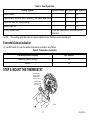
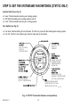
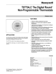
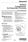
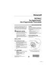
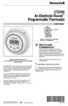
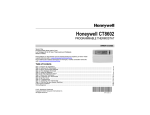
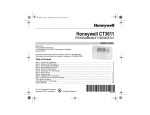
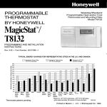
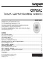
CT8775A,C
THE DIGITAL ROUND™ NON-PROGRAMMABLE THERMOSTATS
OWNER’S GUIDE
CT8775A Heat Only Thermostat (20 to 30 Vac) and
CT8775C Heating-Cooling Thermostat (20 to 30 Vac)
Para obtener un documento con las instrucciones en español, por favor visite
nuestro sitio de web a: www.honeywell.com/yourhome.
Pour obtenir des notices techniques en français, veuillez consulter notre site web
www.honeywell.com/yourhome.
Contents
Step 1. Prepare for Installation ..................................................................................................................................
Step 2. Remove Old Thermostat ...............................................................................................................................
Step 3. Special Installations........................................................................................................................................
Step 4. Label Thermostat Wires .................................................................................................................................
Step 5. Separate Wallplate from Thermostat..............................................................................................................
Step 6. Mount Decorator Cover Plate and Thermostat Wallplate...............................................................................
Step 7. Wire Wallplate Terminals................................................................................................................................
Step 8. Customize the Thermostat .............................................................................................................................
Step 9. Mount the Thermostat ....................................................................................................................................
Step 10. Set the System and Fan Switches ...............................................................................................................
Step 11. Operating the Thermostat.............................................................................................................................
Step 12. Check Operation of Heating and/or Cooling System ...................................................................................
If You Have A Problem ...............................................................................................................................................
Wiring Diagrams.........................................................................................................................................................
® U.S. Registered Trademark • Patents Pending
Copyright © 2004 Honeywell International Inc.
All Rights Reserved
3
4
4
5
5
5
8
10
11
12
13
13
15
16
69-1676—1
Enjoy the benefits of The Digital RoundTM Thermostat by Honeywell.
•
•
•
•
Simple to use. Turn the dial to adjust the temperature setting.
Large easy-to-read display. The temperature reading is easily seen from a
distance.
Backlit display. On-demand backlighting makes it easy to read the display in a dark
room or hallway.
No batteries required. The temperature setting is held permanently in memory in
the event of a power failure.
CO
O LE
R
WAR
ME
R
ROOM
SET
This manual answers many of the questions that can arise as you become familiar and
comfortable with your Honeywell thermostat — the state of the art in home comfort
controls.
M19582
Read these instructions carefully. Failure to follow these instructions can damage the
product or cause a hazardous condition.
MERCURY NOTICE
If this thermostat is replacing a control that contains mercury in a sealed tube,
do not place your old control in the trash. Contact your local waste
management authority for instructions regarding recycling and the proper
disposal of an old control containing mercury in a sealed tube.
MERCURY
SWITCH
TYPICAL LOCATION OF A MERCURY
SWITCH IN A THERMOSTAT
M10614
69-1676—1
2
STEP 1. PREPARE FOR INSTALLATION
❑ Check Table 1, the compatibility chart, to make sure the thermostat is compatible with your system. If your system
is not compatible, call Honeywell Customer Care, toll-free, 1-800-468-1502.
Table 1. Compatibility Chart.
Compatibility with
CT8775A
System Type
Gas or Oil Warm Air
Yes
Electric Warm Air
No
Gas or Oil Hot Water
Yes
Compatibility with
CT8775C
Yes
Yes
a
Yesa
Gas or Oil Steam
Yes
Yes
Gas or Oil Gravity
Yes
Yes
Gas Millivolt
No
No
Electric Air Conditioning
No
Yes
Baseboard Electric (120/240 line volt)b
No
No
Single Stage Heat Pump
No
Yes
Multistage Heat Pumps/Multistage Equipment
No
No
a
Compatible with 2-wire Honeywell zone valves. Not compatible with Taco zone valves and 2- or 3-wire WhiteRodgers zone valves (No. 1311 and 1361).
b
Not compatible with any 120/240 volt system.
Package Contents
•
•
Thermostat
Wiring labels
•
•
Decorator cover plate
Owner’s Guide
•
Screws and wall anchors
•
•
Drill
Drill bits (3/16 in. drywall,
7/32 in. plaster)
•
Hammer
Tools for Installation
•
•
Screwdriver
Needle nose pliers
3
69-1676—1
STEP 2. REMOVE OLD THERMOSTAT
❑ Test your heating and cooling systems to make sure they work properly. If either system does not work, contact
your local heating/air-conditioning dealer. To avoid compressor damage, do not operate the cooling system when
outdoor temperature is below 50°F (10°C).
❑ Turn off power to the system at the furnace or the fuse/circuit breaker panel.
❑ Carefully unpack your new thermostat and decorator cover plate. Save package of screws, instructions, and
receipt.
❑ Remove the cover from the old thermostat. If the cover does not snap off when pulled firmly from the top or bottom,
check for a screw or screws that may be used to lock on the cover.
❑ Loosen the screw or screws (if present) holding the thermostat to the wallplate and lift the thermostat away. Do not
disconnect wires.
STEP 3. SPECIAL INSTALLATIONS
Read this section if you are replacing:
• A thermostat that has wires connected to C or C1 terminals.
• A thermostat that is connected to six or more wires.
• A thermostat that is connected to three wires on a warm air heating only system.
• A thermostat that is connected to three wires on a zoned hot water heating system.
NOTE:
If none of the special installations apply to your particular application, please skip to Step 4.
Replacing a thermostat that has wires connected to C or C1 terminals
If you are replacing a thermostat that has one or two wires connected to C or C1 terminals, do not allow them to touch,
or you can damage the transformer. Wrap the wires separately using electrical tape. Place the wires where they will
not interfere with the operation of the new thermostat. Continue with the installation at Step 4.
Replacing a thermostat that is connected to six or more wires
If you are replacing a thermostat that is connected to six or more wires (excluding wires connected to C or C1
terminals), you may have a multistage heat pump or other multistage system. If you have either one of these systems,
return the product to the place of purchase. This thermostat is not compatible with these systems. For information
about which thermostats will work with your system, call Honeywell Customer Care, at 1-800-468-1502.
69-1676—1
4
Replacing a thermostat that is connected to three wires on a warm air heating only system
If you are replacing a thermostat that is connected to three wires on a warm air heating only system and could turn the
fan on by setting the thermostat fan switch to ON, the CT8775C Thermostat will work with your system. Continue with
the installation at Step 4. If you purchased a CT8775A thermostat, return the product to the place of purchase. The
CT8775A thermostat is not compatible with this application.
Replacing a thermostat that is connected to three wires on a zoned hot water heating system
If you are replacing a thermostat that is connected to three wires on a zoned hot water heating system, the
CT8775A,C thermostats will only work if an isolation relay is installed. For details, call your local heating and/or cooling
contractor.
STEP 4. LABEL THERMOSTAT WIRES
WIRES THROUGH
WALL OPENING
❑ Disconnect the wires from the old thermostat. As you disconnect each wire, attach
the enclosed labels with the old terminal designation. Wrap the wires around a
pencil as shown to keep them from falling back into the wall.
STEP 5. SEPARATE WALLPLATE FROM
THERMOSTAT
M5136
COVER REMOVED
THERMOSTAT
WALL PLATE
❑ Remove cover from thermostat. Separate the wallplate from the
thermostat by placing your thumb on the top between the
wallplate and the thermostat and pulling the thermostat away from
the wallplate. See the illustration at the right.
STEP 6. MOUNT DECORATOR COVER PLATE
AND THERMOSTAT WALLPLATE
M19492
❑ The decorator cover plate and wallplate can be mounted directly
on the wall or onto an electrical box.
❑ To mount directly to the wall, see Fig. 1.
❑ To mount onto an electrical box, see Fig. 2.
5
69-1676—1
Mount Decorator Cover Plate (Optional) and Wallplate Directly to Wall
❑ If using the decorator cover plate, pull the wires through
the wiring hole on the decorator cover plate. Position the
WALL ANCHORS (2)
decorator cover plate against the wall so that the UP
DECORATOR COVER PLATE
indicator in the middle of the decorator cover plate is
pointing up.
❑ Position the wallplate:
❑ If using the decorator cover plate, pull the wires
WALL PLATE
through the wiring hole on the wallplate and place
1 INCH
the wallplate over the decorator cover plate. Turn
SCREW (2)
the wallplate until the wiring holes are aligned and
the two screw holes on the left and right side of the
wallplate line up with the screw holes on the
decorator cover plate. You will be inserting the
screws through these holes into the wall.
❑ If attaching the wallplate directly to the wall, pull the
wires through the wiring hole on the wallplate and
M19493
position it so that the UP indicator on the wallplate is
pointing up.
WIRING HOLES
❑ Use a pencil to mark the center of the screw holes on the
left and right sides of the wallplate.
Fig. 1. Mount decorator cover plate (optional) and
❑ Remove the wallplate and decorator cover plate (if used) wallplate directly to wall (heating-cooling wallplate
and drill two 3/16 in. holes in the wall (if drywall) at the
shown).
locations you marked. For materials such as plaster, drill
7/32 in. holes where marked. Gently tap the provided
anchors into the drilled holes until they are flush with the
wall.
❑ Pull the wires through the wiring holes and reposition the
decorator cover plate (if used) and wallplate over the
screw holes.
❑ Attach the decorator cover plate (if used) and wallplate to
the wall with two 1-in. screws.
69-1676—1
6
.
Mount Decorator Cover Plate (Required) and Wallplate onto Electrical Box
❑ Pull the wires through the wiring hole on the
decorator cover plate.
❑ Place the decorator cover plate against the electrical
box so that the UP indicator in the middle of the
decorator cover plate is pointing up.
❑ Line up the screw slots on the decorator cover plate
with the electrical box screw holes, and attach the
decorator cover plate to the electrical box with two
1/2 in. screws.
❑ Pull the wires through the wiring hole on the
wallplate.
❑ Place the wallplate over the decorator cover plate.
Turn the wallplate until the wiring holes are aligned
and the two screw holes on the left and right side of
the wallplate line up with the screw holes on the
decorator cover plate.
❑ Attach the wallplate to the decorator cover plate with
the two 3/8 in. screws.
BOÎTE ÉLECTRIQUE
PLAQUE D'ADAPTATION DÉCORATIVE
VIS 1/2 PO (2)
PLAQUE DE
COMMUTATION
VIS 3/8
PO (2)
A
1
TROUS DE CÂBLAGE
1
SI LA BOÎTE ÉLECTRIQUE EST
HORIZONTALE, MONTER LA PLAQUE
D'ADAPTATION DÉCORATIVE DANS
LA POSITION ILLUSTRÉE, MAIS
INSÉRER LES VIS DANS LE TROU DE
MONTAGE «A».
MF19494
Fig. 2. Mount decorator cover plate (required) and
wallplate onto electrical box (heating-cooling wallplate
shown).
7
69-1676—1
STEP 7. WIRE WALLPLATE TERMINALS
IMPORTANT
All wiring must comply with local codes and ordinances. If
unsure about household wiring procedures, call your local
heating/air conditioning contractor.
R
G
❑ Refer to the labels you placed on the wires when you removed the
old thermostat (see illustration).
❑ Match the letter of your old thermostat wire with the corresponding
terminal letter on your new thermostat. Refer to Table 2.
IMPORTANT
Remove the factory-installed jumper connecting terminals R
and Rc on the CT8775C Thermostat if wires will be connected to both of these terminals.
❑ For wiring diagrams, see pp 16-17.
❑ Loosen the terminal screws. Slip each wire beneath its matching
terminal. Wraparound and straight connections are both acceptable,
(see illustration). Tighten the terminals.
❑ Plug the hole in the wall with insulation to help prevent drafts from
adversely affecting thermostat operation.
Y
W
FACTORY
INSTALLED JUMPER
M19495
FOR STRAIGHT INSERTION
STRIP 5/16 IN. (8 MM).
FOR WRAPAROUND
INSERTION STRIP
7/16 IN. (11 MM).
M19496
69-1676—1
8
Table 2. Terminal Designations on Old and New Thermostats.
Terminal on
Old
Thermostat
Connect to Terminals
on CT8775A
Connect To Terminals
on CT8775C
Description
R
Rh (see Note 1)
4
V
R
R (see Note 2)
Power
Rc
R (see Note 1)
—
Rc (see Note 2)
Power for cooling
W, W1, H
W
W
Heat
Y, Y1, M
—
Y
Cooling
G, F
—
G
Fan
O
—
O
Changeover in cool. (Single stage heat pump
only).
B (see Note 3)
—
B (see Note 3)
Changeover in heat. (Single stage heat pump
only).
C (see Note 4)
X (see Note 4)
B (see Note 3)
Do not connect.
Do not connect.
Transformer common
W2, H2
Do not continue
installation. Call 1-800468-1502.
Do not continue
installation. Call 1-800468-1502.
Second stage heat.
Y2
Second stage cool.
NOTES:
1. If wires were connected to both Rh and R terminals on the old thermostat, remove jumper between R and Rc on
the new thermostat and connect Rh to R and R to Rc.
2. If wires will be connected to both R and Rc on the new thermostat, remove jumper between R and Rc.
3. Do not connect both O and B when wiring to a single stage heat pump. Connect O to O. Tape off B with electrical tape and do not use.
4. Tape off wire with electrical tape and do not use.
9
69-1676—1
STEP 8. CUSTOMIZE THE THERMOSTAT
Set Fuel Switch (CT8775C Only)
❑ To adjust the fuel switch, locate the switch labeled E/F on the wallplate
(see Fig. 3). The fuel switch is factory set in the F position. This is the
correct setting for gas or oil systems. If you have an electric heat
system, or a heat pump, set the switch to E. The E setting allows the
fan to turn on immediately with the heating system where the G
terminal is connected.
DIP Switch
❑ To adjust the heat cycle rate or the Fahrenheit/Celsius indication,
locate DIP switch 1, 2 and 3 on the back of the thermostat. See Fig. 4.
FUEL SWITCH
❑ Use DIP switches 1 and 2 to set the heat cycle rate. See Table 3.
The CT8775A,C Thermostats will provide optimal temperature
control if DIP switches 1 and 2 are set according to your particular heating system.
Fig. 3. Fuel switch.
BACK OF THERMOSTAT
ON
NOTE:
DIP SWITCH
Fig. 4. DIP switch.
69-1676—1
10
M19497
1 2 3
Set Heat Cycle Rate
M19567
Table 3. Heat Cycle Rate.
Heating System
Cycles Per Hour DIP Switch 1 DIP Switch 2
Steam, Gravity
1
On
On
High Efficiency Warm Air (90%+ efficiency), Hot Water, Heat Pump 3
Off
On
Gas or Oil Warm Air (factory setting)
6
Off
Off
Electric Warm Air
9
On
Off
In Floor Radiant Heat
Check with manufacturer for recommended
cycle rate.
NOTE:
The cooling cycle rate does not require adjustment and therefore cannot be changed.
Fahrenheit/Celsius Indication
❑ Use DIP switch 3 to set the desired temperature indication. See Table 4.
Table 4. Temperature Indication.
Fahrenheit/Celsius Display
DIP Switch 3
Fahrenheit (factory setting)
Off
Celsius
On
STEP 9. MOUNT THE THERMOSTAT
ENGAGE TABS
AT BOTTOM OF
THERMOSTAT
AND WALL PLATE.
PRESS UPPER
EDGE OF CASE
TO LATCH
M19498
11
69-1676—1
STEP 10. SET THE SYSTEM AND FAN SWITCHES (CT8775C ONLY)
System Switch (see Fig. 5)
❑ Heat: The thermostat controls your heating system.
❑ Off: Both the heating and cooling systems are off.
❑ Cool: The thermostat controls your cooling system.
Fan Switch (see Fig. 5)
❑ Fan Auto: Normal setting for most homes. The fan only runs with the heating and cooling system.
❑ Fan On: The fan runs continuously. Use for improved air circulation.
(CT8775C ONLY)
SELECTS
ON/AUTO
(CT8775C ONLY)
SELECTS
COOL/OFF/HEAT
ROOM
SET
SHOWS THAT THE
CURRENT ROOM
TEMPERATURE IS
DISPLAYED
SHOWS THAT THE
CURRENT TEMPERATURE
SETTING IS DISPLAYED
DISPLAYS ROOM
OR SET TEMPERATURE
DISPLAYS AND ADJUSTS
TEMPERATURE SETTING/
TURNS BACKLIGHT ON
M19512
Fig. 5. CT8775 Thermostat (features and operation).
69-1676—1
12
STEP 11. OPERATING THE THERMOSTAT
NOTE:
Batteries are not required because the temperature setting is held permanently in memory.
Backlit Display
❑ The backlight can be turned on by turning the dial, or pushing the backlight button (see Fig. 5).
Display Temperature Setting
❑ Turn the dial one click to display the temperature setting (see Fig. 6). A
indicator points to Set when the temperature setting is displayed.
ROOM
SET
M19489
Fig. 6. Temperature Setting Display.
❑ If a change to the temperature setting is not made within five seconds, the
mode will switch to the room temperature display (see Fig. 7). A
indicator
points to Room when the room temperature is displayed.
ROOM
SET
M19490
Fig. 7. Room Temperature Display.
Adjust Temperature Setting
❑ Turn the dial clockwise to raise the temperature setting. Turn the dial counterclockwise to lower the temperature
setting.
STEP 12. CHECK OPERATION OF HEATING AND/OR COOLING SYSTEM
Heating System
❑
❑
❑
❑
❑
Slide the system switch to Heat and the Fan switch to Auto (CT8775C only).
Turn the dial clockwise to raise the temperature setting several degrees above the room temperature.
A flame will appear in the display to indicate the thermostat has called for heating. The heating system should turn on.
Turn the dial counterclockwise to lower the temperature setting below the room temperature.
The flame will disappear from the display to indicate the thermostat has ended the call for heating. The heating
system should turn off.
13
69-1676—1
Cooling System (CT8775C Only)
CAUTION
Equipment Damage Hazard.
Can cause permanent damage to compressor or other equipment.
Do not operate cooling when outside temperature is below 50°F (10°C).
Allow compressor to remain off for five minutes before restarting.
See equipment manufacturer instructions.
❑ Slide the system switch to Cool and the Fan switch to Auto.
❑ Turn the dial counterclockwise to lower the temperature setting several degrees below the room temperature.
NOTE:
If a call for cooling is made before the compressor has been off for five minutes, or if a power interruption
occurs while the compressor is running, the thermostat will go into a five-minute delay to protect the compressor. The snowflake
will flash during this delay.
❑ After five minutes, the thermostat will display a solid snowflake
to indicate the thermostat has called for cooling.
The cooling system should turn on.
❑ Turn the dial clockwise to raise the temperature setting above the room temperature.
❑ The snowflake
will disappear from the display to indicate the thermostat has ended the call for cooling. The
cooling system should turn off.
Fan (CT8775C Only)
❑ Slide the system switch to Off and the fan switch to On. The fan should run continuously.
❑ Slide the Fan switch to Auto. The fan should turn off.
69-1676—1
14
IF YOU HAVE A PROBLEM
Table 5. Solution Guide.
If...
Display does not appear.
Then…
Make sure the thermostat is wired correctly. Refer to Table 2 or the
wiring diagrams.
• Make sure the thermostat is mounted and latched on the wallplate.
• Make sure the circuit breaker is not tripped, and reset it if necessary.
• Make sure the power switch at the equipment is in the On position and
set it to On if it is in the Off position.
Temperature settings will not change
• Make sure the temperature settings are:
(example: cannot set the heating higher
40 to 90°F (4 to 32°C) for heating.
or the cooling lower).
45 to 99°F (7 to 37°C) for cooling.
Heating does not come on.
• Set the system switch to Heat (CT8775C only).
• Make sure the temperature setting is above the room temperature.
• Make sure the circuit breaker is not tripped, and reset it if necessary.
• Make sure the power switch at the equipment is in the On position, and
set it to On if it is in the Off position.
• Wait five minutes for the system to respond.
Cooling does not come on.
• Set the system switch to Cool (CT8775C only).
• Make sure the temperature setting is below the room temperature.
• Make sure the circuit breaker is not tripped, and reset it if necessary.
• Make sure the power switch at the equipment is in the On position, and
set it to On if it is in the Off position.
• Wait five minutes for the system to respond.
System on indicator ( = heat,
=
Wait five minutes after seeing the flame or snowflake and check the
cool) is lit, but no warm or cool air is
registers again. If there is no warm or cool air coming from the registers,
coming from the registers.
refer to Heating does not come on or Cooling does not come on. If all of this
has been checked, contact your local heating and cooling contractor.
•
Customer Assistance
Please read and follow the provided instructions for this thermostat. For additional information, go to
www.honeywell.com/yourhome or call Honeywell Customer Care, toll free, at 1-800-468-1502.
Before calling, please have the following information available:
• Thermostat model number. (Located on back of thermostat).
• Thermostat date code. (Located below model number).
• Type of heating/cooling system (example: Gas, oil, or electric; warm air, hot water, heat pump, steam or gravity).
• Location and number of wires connected to the thermostat.
15
69-1676—1
Wiring Diagrams
O
2
R
Rc
R
W
1
HEATING
RELAY OR
VALVE COIL
1
HEATING
RELAY OR
VALVE COIL
2 FACTORY INSTALLED JUMPER.
M19450
O
2 Rc
1
B
G
Y
W
HEATING
RELAY OR
VALVE COIL
COMPRESSOR
CONTACTOR
FAN
RELAY
1 POWER SUPPLY. PROVIDE DISCONNECT MEANS
AND OVERLOAD PROTECTION AS REQUIRED.
2 FACTORY INSTALLED JUMPER.
M19452
69-1676—1
G
Y
W
FAN
RELAY
1 POWER SUPPLY. PROVIDE DISCONNECT MEANS
AND OVERLOAD PROTECTION AS REQUIRED.
1 POWER SUPPLY. PROVIDE DISCONNECT MEANS
AND OVERLOAD PROTECTION AS REQUIRED.
R
B
16
M19451
4
O
Rc
2
R
O
B
COMPRESSOR
CONTACTOR
1
B
G
Y 3
W
2
Rc
R
G
Y
W
HEAT
CHANGEOVER
VALVE
FAN
RELAY
COMPRESSOR
CONTACTOR
COOL
CHANGEOVER
VALVE
1
HEATING
RELAY OR
VALVE COIL
FAN
RELAY
1
1 POWER SUPPLY. PROVIDE DISCONNECT MEANS
AND OVERLOAD PROTECTION AS REQUIRED.
2 FACTORY INSTALLED JUMPER.
M19453
3 USE A JUMPER WIRE (NOT SUPPLIED) TO CONNECT W TO Y.
1 POWER SUPPLY. PROVIDE DISCONNECT MEANS
AND OVERLOAD PROTECTION AS REQUIRED.
4 USE EITHER O OR B FOR HEAT PUMP CHANGEOVER.
2 REMOVE FACTORY INSTALLED JUMPER BETWEEN R AND RC.
M19454
Notice:
This thermostat is a Class B digital apparatus that complies with Canadian Radio Interference Regulations,
CRC c. 1374.
17
69-1676—1
Limited One-Year Warranty
Honeywell warrants this product to be free from defects in the workmanship or materials, under normal use and service, for a period of
one (1) year from the date of purchase by the consumer. If, at any time during the warranty period, the product is defective or
malfunctions, Honeywell shall repair or replace it (at Honeywells option) within a reasonable period of time.
If the product is defective,
(i)
return it, with a bill of sale or other dated proof of purchase, to the retailer from which you purchased it, or
(ii) package it carefully, along with proof of purchase (including date of purchase) and a short description of the malfunction, and mail it, postage
prepaid, to the following address:
Honeywell USA
Honeywell Canada:
Dock 4 — MN10-3860
Honeywell Limited/Honeywell Limitée
1885 Douglas Drive North
35 Dynamic Drive
Golden Valley, MN 55422-3992
Scarborough, Ontario M1V 4Z9
This warranty does not cover removal or reinstallation costs. This warranty shall not apply if it is shown by Honeywell that the defect or
malfunction was caused by damage which occurred while the product was in the possession of a consumer.
Honeywells sole responsibility shall be to repair or replace the product within the terms stated above. HONEYWELL SHALL NOT BE
LIABLE FOR ANY LOSS OR DAMAGE OF ANY KIND, INCLUDING ANY INCIDENTAL OR CONSEQUENTIAL DAMAGES
RESULTING, DIRECTLY OR INDIRECTLY FROM ANY BREACH OF ANY WARRANTY, EXPRESS OR IMPLIED, OR ANY OTHER
FAILURE OF THIS PRODUCT. Some states do not allow the exclusion or limitation of incidental or consequential damages, so this
limitation may not apply to you.
THIS WARRANTY IS THE ONLY EXPRESS WARRANTY HONEYWELL MAKES ON THIS PRODUCT. THE DURATION OF ANY
IMPLIED WARRANTIES, INCLUDING THE WARRANTIES OF MERCHANTABILITY AND FITNESS FOR A PARTICULAR PURPOSE,
IS HEREBY LIMITED TO THE ONE YEAR DURATION OF THIS WARRANTY. Some states do not allow limitations on how long an
implied warranty lasts, so the above limitation may not apply to you.
This warranty gives you specific legal rights, and you may have other rights which vary from state to state.
If you have any questions concerning this warranty, please write Honeywell Customer Care, 1885 Douglas Dr. N., Golden Valley, MN
55422-3992. In Canada, write Retail Products ON30 Honeywell Limited/Honeywell Limitée, 35 Dynamic Drive, Scarborough, Ontario
M1V 4Z9.
69-1676—1
18
19
69-1676—1
Automation and Control Solutions
Honeywell International Inc.
1985 Douglas Drive North
Golden Valley, MN 55422
69-1676—1
J.S. Rev. 6-04
Honeywell Limited-Honeywell Limitée
35 Dynamic Drive
Scarborough, Ontario
M1V 4Z9
www.honeywell.com/yourhome