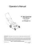
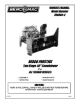
1
SB7038 Snowblower
The information in this operator’s manual is limited in application to the Honda SB7038 Snowblower when
installed and used on a Honda mid-sized commercial mower power head. Before installing or operating
this equipment, read this operator’s manual and the owner’s manual supplied with the power head.
All information in this publication is based on the latest product information available at the time of
printing. American Honda Motor Co., Inc. reserves the right to make changes at any time without notice
and without incurring any obligation. No part of this publication may be reproduced without written
permission.
This manual is a permanent part of the snowblower and must stay with the snowblower
POP 52173 (9511)
if resold.
1
SB7038 Snowblower
Table Of Contents
THE IMPORTANCE
OF INSTALLATION
.......................................................................................
IMPORTANT SAFETY PRECAUTIONS.. .........................................................................................................
Safety Labels ....................................................................................................................................................
Assembly
I
and Installation
.............................................................................................................
Inventory Loose Parts.. ......................................................................................................................................
Inventory Hardware Bags ..................................................................................................................................
Hardware Measuring Chart.. ..............................................................................................................................
Torque Values.. ..................................................................................................................................................
Uncrate the snowblower.. ..................................................................................................................................
Remove the Mower Deck.. .................................................................................................................................
Install the Tension Release Control ..................................................................................................................
Assemble the Snowblower.. ...............................................................................................................................
Install the Snowblower.. ...................................................................................................................................
...........................................................................................................
Safety Recommendations
Introduction ......................................................................................................................................................
Training ............................................................................................................................................................
Preparation ......................................................................................................................................................
Before Operation.. ............................................................................................................................................
Operation .........................................................................................................................................................
Children.. ..........................................................................................................................................................
Stopping ...........................................................................................................................................................
Maintenance ....................................................................................................................................................
Controls.. ..........................................................................................................................................................
3
.3
.4
5
5
6
7
7
8
8
.8
9
11
15
15
15
15
16
16
17
18
18
19
Deflector Cable Removal.. ...............................................................................................................................
Chute Rotator Removal ...................................................................................................................................
Snow Blower Removal.. ...................................................................................................................................
Storing the Snow Blower.. ................................................................................................................................
22
22
22
22
22
.......................................................................................................
23
Maintenance Schedule ....................................................................................................................................
Adjustments ....................................................................................................................................................
Other Maintenance Items.. ...............................................................................................................................
23
.23
24
Removing
and Storing
Maintenance
Parts Listing
the Snowblower
& Adjustments
....................................................................................
.................................................................................................................................
26
..................................................................................................................
28
Headlight Kit.. ...................................................................................................................................................
Engine Cold Weather Kit ................................................................................................................................
AG Tire Kit .......................................................................................................................................................
28
.28
28
Optional
Warranty
POP 52173 (9511)
Accessories
Service
Information
. . .. . .. . .. .. . .. . . ... . .. . .... . .. . .. .. . .. . . ... . .. . . ... . . .. . .. . .. .. . . .. . .. . . .. . .. .. . . .. . . .. . . .. . . . .. .. . . 29
2
8
THE IMPORTANCE
Proper installation is essential to operator safety and the reliability of the machine. Any error or oversight
made by the technician assembling and servicing a unit can easily result in faulty operation, damage to
the machine, or injury to the operator.
0
8
OF INSTALLATION
Improper service can cause an unsafe condition
that can lead to serious injury or death.
Follow the procedures and precautions in
installation instructions and shop manuals
carefully.
Some of the most important safety precautions are given below. However, we cannot warn you of every
conceivable hazard that can arise in performing this installation. Only you can decide whether or not you
should perform a given task.
Failure to properly follow installation instructions
and precautions can cause you to be seriously
hurt or killed.
Follow the procedures and precautions in
installation instructions carefully.
8
IMPORTANT
SAFETY PRECAUTIONS
Make sure you have a clear understanding of all basic shop safety practices and that you are wearing
appropriate clothing and safety equipment. When performing this installation, be especially careful of the
following:
l
Read the instructions before you begin, and make sure you have the tools and skills required to
perform the tasks safely.
Make sure the engine is off before you begin any maintenance or repairs. This will help eliminate several
potential hazards:
l
l
l
Carbon monoxide poisoning from engine exhaust. Be sure there is adequate ventilation whenever
you run the engine.
Burns from hot parts. Let the engine and exhaust system cool before touching.
Injury from moving parts. Do not run the engine unless the instruction tells you to do so. Even
then, keep your hands, fingers, and clothing away. Do not run the engine when any protective
guard or shield is removed.
To reduce the possibility of a fire or explosion, be careful when working around gasoline or batteries. Use
only a nonflammable solvent, not gasoline, to clean parts. Keep all cigarettes, sparks, and flames away
from the battery and all fuel-related parts.
POP 52173 (9511)
3
SB7038 Snowblower
Safety Labels
Immediately replace any label that becomes damaged or unreadable. Contact a servicing Honda
commercial mower dealer for replacement label.
FAILURE TO FOLLOW SAFE OPERATING PROCEOU
RES MAY RESULT IN INJURY.
l FOR SAFE OPERATION
FOLLOW ALL
OPERATlNG INSTRUCTIONS AND SAFETY
PRECAUTIONS IN OPFRATcX?S MANUAL.
•T~~E~ROTECTION
MUST BE WORN ATALL
KEEP HANDS,
HANDS
FEET
AND CLOTHING AWAY
_^_..
--... -L FE
-_
FROM POWER DRIVEN PARTS.
ENGINE BEFORE LEAVlNG OPERATOR
PUSTTION.
POSITION.
l WAIT FOR ALL MOVEMENTS
TO STOP BEFORE
STARTING TO ADJUST, LUBRICATE. CLEAN OR
UNCLOG THE MACHINE.
l KEEP THE
TH AREA OF OPERATlON CLEAR OF
ALL PERSONS AND
Ah ANIMALS.
’l KEEP ALL GUARDS
GUARt
AND SHIELDS IN PLACE,
l NEVER DIRECT DISCHARGE
DI
TOWARD SYSIJIL,
STANDERS, BUILDINGS.
CARS ETC.
-ALWAYS USE A 01
OUST MASK WHEN WORKING
IN DUSTY CONDITIONS.
l KEEP PLASTIC
MATERIALS AWAY FROM
INTENSE HEAT AND OPEN FLAME.
I
*NEVER ALLOW
PASSENGERS ON THE
ATTACHMENT.
ATTACH
l
.-STOP
AVOID INJURY
FROM
ROTATING
AUGER
KEEP HANDS,
FEET AND
CLOTHING
AWAY
NUMBER
POP 52173 (9511)
J
Assembly and Installation
SB7038 Snowblower
Assembly
and Installation
1. Remove the lag bolts holding the blower head and the pulley
assembly to the shipping pallet.
-
2. Remove the blower head and pulley assembly from the pallet.
3. Remove the loose parts box, then inventory the contents.
Inventory
Loose Parts
SKID SHOES (2)
WORM SUPPORT
DISCHARGE
BRACKET
CABLE BRACKET
CABLE BRACKET SPACER
WORM GEAR
CABLE ASSEMBLY
GUARD
SPARE SHEAR BOLT
HARDWARE BAG
LARGE HARDWARE
BAG
UPPER CRANK ROD
HANDLE SUPPORT
/
LOWER CRANK ROD
\
DISCHARGE
POP 52173 (9511)
CHUTE
TENSION
ANTIFRICTION
2
RELEASE ROD
RING
5
Assembly and Installation
Inventory
Large Hardware
SB7038 Snowblower
Bag
There is a large and small hardware bag. The hardware in the large bag are used for the initial assembly
and installation, while the hardware in the small, resealable bag consists of spare shear bolts.
Be sure to inventory all hardware in the large bag before assembling the snowblower.
tie wrap, 4”
plastic cable boot
l/2” flat washer (2)
The smaller, resealable hardware bag contains:
l/4 x 1” fan shaft shear bolt, hex head (2)
5/16 x 2-l/4 auger shaft shear bolt, hex head (2)
l/4” self-locking hex nut (2)
5/16” hex nut (2)
5/l 6” lockwasher (2)
.
These spare parts should be used in the event a shear bolt on the auger or fan shaft breaks.
SB7038 Snowblower
a
Hardware
Assembly and Installation
Measuring
How to measure
Chart
hardware
and components:
INCHES
1
0
4
3
2
IIIl,lllI
0
10
20
30
40
50
60
70
80
90
6
5
100
IIll,IIII llll,IIII
I,,,,,,,,
I
I
I
110
120
130
IllIll
I ,,,,,,,,, I
140 150
MILLIMETERS
518in
00
5mm
6mm
9/l 6 In
amm
II2 In
7/l 6 In
10mm
12mm
318 In
5/i 6 In
l/4 In
14 mm
INSIDE
DIAMETER
WASHERS ARE
BY INSIDE DIAMETER
NUTS ARE SPECIFIED
BY INSIDE DIAMETER.
(AT THREAD DEPTH)
Torque Values
Nom
Fastener I Size
ft-lb.
Hex nut / bolt, l/4”
6.8-8.1
5-6
Hex nut I bolt, 5/l 6”
14-16
10-12
Hex nut I bolt, 318”
I
27-31
I
20-23
Hex nut I bolt, 7/l 6”
41-47
30-35
Hex nut 1 bolt, l/2”
61-70
45-52
8 x 25 mm flange bolts
9-19
7.2-14
I
SB7038 Snowblower
Assembly and Installation
Remove the Mower Deck
1. Follow the procedure in the HRC 7000~series Owner’s Manual or Shop Manual and remove the
mower deck from the power head.
2. Save the bolts and flange nuts to use with the mower deck when it is reinstalled.
Install the Tension
Release Control
(hydrostatic
drive models)
1. Assemble the pivot pin on the release plate with three 5/l 6” flat washers and a cotter pin as shown.
2. Raise and support the rear of the power unit to reach the pump belt tensioner.
3. Remove the tensioner pivot bolt and belleville washer.
FLANGE NUT
u
./
LEFT PUM+ PULLEY
\
/A
RIGHT PUMP PULLEY
/
3
CRANKSHAFT
PULLEY
\
TENSIONER
\ TENSIONER PIVOT BOLT’
S/32” SPACER
I
4. Install the belleville washer, release plate, and
spacer over the new pivot bolt.
5. Install the pivot bolt through the tensioner and
into the engine bed. Install the flange nut on the
tensioner bolt and tighten the bolt.
BELLEVILLE
PLATE
5116” FLAT WASHER (3)
PIVOT PIN ’
Assembly and Installation
SB7038 Snowblower
6. Hold one of the face plates behind the
opening in the engine bed. Slide the
threaded end of the release rod through
the opening and the slot in the face plate.
7. Thread the release rod into the pivot pin
until the edge of the welded plate on the
rod is 3 mm (l/W) from the engine bed.
a. Position the second faceplate as shown.
Install two 5/l 6 x 1” hex bolts and 506”
flange nuts to securely tighten the
faceplates to the engine bed.
5/16 x 1” HEX BOLT (2)
9. Verify that the release rod slides in and
out of the face plates and operates the
release plates properly.
Assemble
the Snowblower
Chute Assembly
1. Install the discharge guard on the chute with the
top portion inside the chute and the bottom section
outside the ring base. Fasten the guard with two
114 x 3/4” hex bolts, 5/l 6” flat washers, l/4” lock
washers and l/4” hex nuts.
. 2. Install the two springs as shown.
DISCHARG
GUARD
SB7038 Snowblower
Assembly and Installation
3. Lightly coat the top side of the anti-friction
ring with general purpose grease, and
place it over the chute base. The ring is
keyed and will only fit on the chute base
one way.
114 x 314” HEX BOLT (2) l/4 x 112” HEX BOLT (6)
WORM GEAR
l-511 6”
ANTI-FRICTION
4. Insert the shorter plastic (l-5/1 6”) bushing
into the boss on the blower head. Insert
the longer bushing (l-l l/16”) in the worm
support bracket.
5. Lightly coat both shafts of the worm with
general purpose grease. Insert the longer
end of the worm through the worm support
bracket, and insert the shorter end into the
boss on the blower head.
6. Install the chute over the anti-friction ring,
and place the four retaining plates into
position over the chute sector. Insert two
l/4 x 3/4” bolts through the retaining plate,
housing, and worm support bracket.
Secure the bolts with l/4” lock washers
and l/4” hex nuts.
7. Attach the remaining three retaining plates in a similar manner using l/4 x l/2” bolts.
Skid Shoe Assembly
1.
/
5/16x1”
Insert two 5/16 x 1” carriage bolts through a skid
shoe as shown. Loosely install a 51/6” lock washer
and 5/16” hex nut on each bolt.
2. Place the bolt heads through the holes on the rear
of the housing, and slide the square shanks into the
slots. Tighten the nuts.
3. Repeat the process for the shoe on the other side.
Adjust the skid shoe height (page 23) after installing
the snowblower.
5/16’ HEX NUT (2(
SB7038 Snowblower
Assembly and Installation
Install the Snowblower
1. Check that the power unit is in “Low Range” at the 2-l/2” cutting-height position. Refer to the
mid-sized commercial mower owner’s manual or shop manual as needed.
2. Loosen the two belt guards around the crankshaft pulley. Refer to the mid-size commercial mower
owner’s manual or shop manual for details.
3. Install a l/2” flat washer on the axle tie bolt, then install the
original axle tie nut. On hydrostatic drive models, open the
pump bypass valves.
ORIGINAL
4. Place the power unit directly behind the snowblower and
remove the belt cover. Raise and support the underside of
the snowblower.
5. Connect the power unit to the snow thrower using eight
l/2 x 1” bolts and eight l/2” flange nuts.
6. Install the snow blower belt on the engine pulley and
tensioner. Adjust the belt tension (see the mid-size
commercial mower owner’s manual or shop manual ).
7. Replace the belt cover.
AXLE NUT (
SB7038 Snowblower
Assembly and Installation
Chute Rotator
Assembly
1. Install the crank support on the power head with two 3/8 x 1” bolts and flange nuts.
2. Install the grommet through the hole in the support.
PLASTIC
HANDLE
UPPER CRANK ROD
3. Attach the lower crank rod to the worm gear by placing the hook on the lower crank rod through the
hole in the worm gear shaft.
4. Insert the upper crank rod through the grommet in the crank support and into the the lower crank rod.
Secure it with a 2-15/16” spring clip. Install the plastic handle over the end of the upper crank rod.
.
Assembly and Installation
SB7038 Snowblower
Deflector
Cable Assembly
1. Remove the forward throttle mounting screw, and use it
to temporarily hold the cable bracket in position.
The cable bracket will be used as a guide to mark, and
drill the two mounting bolt holes in the handle tube.
Position the cable bracket so it is parallel to the right side
handle tube.
2. Use a center punch to mark the center of one of the
holes in the upper bracket. Put on safety glasses and drill
a 21/64” hole into the handle tube. Install a bolt through
the drilled hole to hold the location, and drill the second
hole through the handle.
3. Remove the cable bracket and deburr the drilled holes in
the handle tube.
CABLE
BRACKET
\\
5716 x 2” HEX BOLT (2)
4. Put the cable bracket and spacer into position and secure
them with the throttle screw and two 5/16x2” bolts,
washers, and flange nuts as shown.
5/16” FLAT WASHER (
5/16” FLANGE NUT (2)
PLASTIC BOOT
5. Carefully stretch the protective plastic boot over the
choke knob. Use the small 4” cable tie to secure the boot
to the underside of the choke knob.
This plastic boot will help prevent snow and moisture
from getting into the choke cable.
4” CABLE TIE
FASTEN BOOT
UNDER CHOKE
KNOB
Assembly and Installation
SB7038 Snowblower
6. Route the cable behind the fuel tank and above
the the speed control arms. On 7018/20 models,
thread the cable through the same slot on the
fuel support bracket used by the choke and
throttle cables.
7. On 7013 models, use the 7” cable tie to secure
the cable to the left-side tank support. On
7018/20 models route the cable behind the fuel
pump bracket.
8. Once the cable has been positioned, install it to the bracket and
tighten the bottom jam nut on the T-handle.
9. The cable clamp is keyed to fit a groove on
the cable. Make sure the clamp and cable
are properly aligned before securing the
cable to the discharge chute with the spacer,
two lo-24 screws, lock washers, and hex
nuts.
10. Screw the clevis onto the cable. With the chute
held fully down by its springs, and the T-handle
of the cable fully in, adjust the position clevis so
the clevis pin slips through the hole in the
deflector arm.
CLAMP MACHINE
11. Secure the clevis pin with small cotter pin, and
tighten the jam nut against the clevis.
14
LOCK WASHER
(2)
POP 52173 (9511)
SB7038 Snowblower
Safety Recommendations
Safety Recommendations
Introduction
1. The snowblower is capable of amputating hands and feet and throwing objects. Failure to observe the
following safety instructions could result in serious injury or death.
2. Serious accidents which may cause injury or property damage can occur if the following safety
guidelines are not followed. The operator is solely responsible for accidents or hazards that occur when
using the snowblower. Preventing accidents is the responsibility of every equipment operator.
Accidents can be prevented. Be careful before, during and immediately after use of any powered
equipment. The following general safety precautions must be fully understood and followed during
operation. Review these instructions frequently and never take chances. If you do not understand any
part of this manual or need assistance, contact your authorized, servicing Honda commercial mower
dealer.
Training
1. Read, understand and follow all instructions in this manual and on the snowblower before starting. To
order-a replacement manual, contact an authorized, servicing Honda commercial mower dealer, or
Honda Customer Service.
2. Read and understand
the mid-sized commercial mower owner’s manual.
3. Allow only responsible adults, who are familiar with the instructions,
to operate the machine.
4. Know the location of all controls before operating the machine. Know how to stop the engine and
attachments quickly in case of emergency. Familiarize yourself with all safety and operation labels on
the machine and attachments. If these labels are damaged or not legible, clean or replace them.
Preparation
1. Wear proper clothing when operating the snowblower. Always wear sturdy footwear (preferably
steel-toed shoes) and hearing protection during operation.
a) Wear heavy, leather gloves whenever working near or servicing any cutting edges on the
snowblower.
b) Do not wear loose fitting clothing, jewelry, scarves,, ties, etc., which may get caught in moving parts.
Tie up or restrain long hair.
c) Do not operate the snowblower while barefoot.
d) Do not wear sandals
e) Wear long trousers.
f) Wear hearing protection.
g) Do not operate the snowblower when tired, ill, or under the influence of alcohol and/or other drugs.
2. Be prepared for an emergency. Keep a first aid kit and fire extinguisher handy. Keep emergency
telephone numbers for ambulance, fire, hospital, doctor and rescue near your telephone.
SB7038 Snowblower
Safety Recommendations
Before Operation
1. Before each use, clear work area of objects such as rocks, toys, wire, sleds, etc., which could be
picked up and thrown.
2. Keep the snowblower
a)
b)
in safe operating condition. Check the following each time before use:
All hardware for tightness (refer to the torque table for details).
Inspect auger and fan blades for wear or damage. Broken pieces thrown from worn or damaged
auger or fan can cause serious injury.
c) Check for and maintain correct tire pressure. Check tires for cuts or bubbles. Check wheels for
damage or for missing hardware. Repair or replace as required.
4 Check the engine oil level and add oil as required. If oil level falls below the fill mark, do not run
engine.
3. Do not operate the snowblower without safety devices and shields in place and operating properly.
4. The power head is equipped with operator presence levers that shut off the engine unless they are being
held down by an operator while the speed control levers are not in neutral, or if the blade control lever is
ON. If the interlock system is not working properly, repair it before operating the snowblower.
Correct any malfunction
before using this snowblower with the power head.
INOTICE]
Do not use tire chains. Using tire chains may damage the hydraulic lines near the tires. Use of the
AG (bar-tread) tires is recommended for maximum traction.
Operation
1. When starting the engine:
a) Disengage the blade control lever.
b) Move the shift levers to NEUTRAL.
2. Always stand behind the power head when operating
the snowblower.
3. Keep hands, feet, face, hair and clothing away from rotating parts. Stop engine before unclogging chute.
4. When operating the snowblower:
Disengage the blade control lever, shut off engine, remove the ignition key, and wait for all moving
parts to stop before unclogging discharge chute or auger blades.
5. Disengage the blade control lever when transporting,
or when the snowblower
is not in use.
6. Be aware of snowblower discharge direction and do not point it at anyone. Do not operate without
discharge deflector in place.
7. If you strike a foreign object, disengage the blade control lever, shut off the engine, set the parking
brake on, and remove the ignition key. Inspect for and repair any damage before operating the
equipment again.
8. Never carry passengers. Passengers interfere with safe operation of the snowblower. Passengers
could be struck by foreign objects and/or be thrown from the machine and could be severely injured.
9. Be sure the area is clear of other people before operation. Stop the machine if anyone enters the
area. Do not operate the machine with children, pets, or other nearby.
Safety Recommendations
SB7038 Snowblower
lO.As a general rule, do not operate the snowblower in reverse. If it is absolutely necessary to back up:
a) Disengage the blade control.
b) Check the area on the ground directly behind the machine.
c) Continue to observe area down and to rear while backing up.
11 .Approach blind corners cautiously.
12.Always observe the terrain. Watch for and avoid obstacles. Stay away from holes, ditches, soft or
steep embankments and other potentially dangerous terrain.
13. Wet surfaces reduce traction and stability. Always maintain proper traction. Grip the handlebars firmly.
14.Slow down before turning.
15.Watch out for traffic when operating near or crossing roadways.
16. Never leave a running machine unattended. Always disengage the blade control lever, and remove
the ignition key before leaving the snowblower.
Children
1. Accidents can occur if the operator is not alert to the presence of children. Children are often attracted
to the machine and the snowblowing activity. Never assume that children will remain where you last
saw them.
-
2. Never allow children to operate the machine, even under adult supervision. Local regulations may restrict
operator age. Allow only responsible adults, who are familiar with these instructions, to operate this unit.
3. Never carry children as passengers. They may fall off or be seriously injured or interfere with safe
machine operation.
4. Keep children out of the work area and under the watchful eye of another responsible adult.
5. Be alert and turn off the machine if children enter the area.
6. Before and when backing, look behind and down for small children.
7. Use extreme care when approaching
vision.
blind corners, drifts, trees or other objects that may obscure
8. Keep children away while performing maintenance or adjustments.
SB7038 Snowblower
Safety Recommendations
Stopping
1. Before leaving operator’s position or leaving the machine unattended:
a) Bring the snowblower
to a complete stop.
b) Move the blade control lever to OFF.
c) Move the speed control levers to NEUTRAL.
d) Shut off the engine and remove the ignition key.
e) Wait for all moving parts to come to a complete stop.
2. Disengage the blade control lever when transporting
use.
the snowblower or if the snowblower
is not in
Maintenance
1. Before performing any service, adjustments or maintenance
on the machine:
a) Park the machine on a firm, level surface.
b) Move the blade control lever to OFF.
c) Move all control levers to NEUTRAL.
d) Shut off the engine. Remove the ignition key. Allow the engine to cool.
2. Always wear sturdy footwear (preferably steel-toed shoes), long trousers, hearing and eye protection
while performing maintenance on the machine. Do not wear loose fitting clothing, jewelry, scarves,
ties, etc., which could get caught in moving parts. Tie up or restrain long hair.
3. Auger and fan blades are extremely sharp. Use caution when servicing. Wear heavy gloves.
4. Keep children away while performing maintenance
or adjustments.
5. Keep nuts and bolts tight. Keep equipment in good condition.
6. Never tamper with safety devices. Check their proper operation regularly. Replace or repair as
necessary.
7. Keep machine free of dirt and grime. Clean up oil or fuel spillage. Allow machine to cool before storing.
8. Frequently check components and replace when necessary. Use only factory-approved
parts. Parts manufactured by others may not be of the same quality.
replacement
9. Keep all safety and operation labels in place. If these labels are damaged or not legible, clean or
replace them as needed.
10. Chock snowblower wheels (place blocks of wood in front of and behind wheels) when performing
maintenance. Securely support unit if it must be raised for any reason.
11. Do not inflate the tires above recommended pressures. Use a clip-on chuck to inflate tires, with an
extension long enough for you to stand to one side, and not over or in front of the tire assembly.
18
POP 52173 (9511)
SB7038 Snowblower
a
a
a
Safety Recommendations
Controls
Use this section to familiarize yourself with the various controls and operation of the snowblower. This
section covers only items relating to the snowblower itself. Refer to the owners manual for the Honda
mid-size commercial mower for instructions in operating the power unit.
Description
of Controls
Hydraulic Drive Release
Pull this lever out and rotate it to lock and
disengage the hydraulic drive pumps from
the engine. This reduces the load on the
engine for starting in extremely cold
weather.
CHUTE ROTATION
CRANK
Chute Rotation Crank
Rotating this crank turns the discharge
chute. The discharge chute will rotate a
250 degree arc.
Deflector Control
a
This determines the angle at which snow is
discharged from the chute. The locking
T-handle next to the throttle sets the chute
at the desired angle. Turn the handle
counter-clockwise l/4 turn to loosen, then
pull or push the handle to adjust the
deflector angle. Turn the handle clockwise
l/4 turn to lock into position.
HYDRAULIC
RELEASE
DRIVE
Blade Control Lever
Use this lever to engage engine power to the
snowblower. Move the lever forward for on, and pull it back for off.
Preparing
a
for Snow Removal
For your safety and the service life of your equipment, always inspect the snowblower before using it. In
addition to the inspection areas in the mid-sized commercial mower owner’s manual, check the following
areas of the snowblower. Before beginning any inspection:
1. Park the unit on a flat, level surface.
2. Disengage the blade control lever and put the forward speed control levers in neutral.
3. Turn the ignition switch off and remove the key.
a
a
4. Make sure the auger blades, blower head and discharge chute are free of any debris or objects.
5. Check the shear bolts for tightness.
piq
To prevent damage to the snowblower, never operate the snowblower With a loose or damaged
shear bolt. Always use special extended-shoulder shear bolts on the fan assembly and grooved
shear bolts on the auger sections.
POP 52173 (9511)
19
SB7038 Snowblower
Safety Recommendations
6. Inspect the position of the two skid shoes and make sure they
are properly positioned for conditions. Allow l/8” to 3/l 6”
clearance between cutting edge and a level paved surface, or
l/4” to l/2” for an uneven or gravel surface.
LOOSEN (don’t remove)
NUTS
7. Verify the tension on the drive belt is correct. See the mid-sized
commercial mower owner’s manual for details on inspecting
and adjusting drive belt tension.
8. If the temperature is extremely cold, it will be easier to start the
engine if you disengage the hydraulic drive pumps. Pull the
hydraulic release rod out, then rotate it so the square plate
holds the rod away from the engine bed.
9. Follow the procedure in the mid-sized commercial owner’s
manual and start the engine.
10. One the engine has started, pull and turn the hydraulic release rod.
Operating
118 - 3116” LEVEL SURFACE
114 - 112” GRAVEL OR UNEVEN SURFACE
the snowblower
Read the mid-size commercial mower owner’s manual carefully.
the controls and proper use of the power head and snowblower.
snowblower
and disengage the controls quickly.
Never allow children
snowblower
without
to operate the snowblower.
proper instruction.
Do no allow anyone
other than the operator
Keep the area of operation
Be thoroughly
familiar with
Know how to stop the
Never allow anyone
to operate the
on the snowblower.
clear of all people and pets.
Clothing worn by the operator should be fairly tight and belted. Loose clothing
be permitted because of the danger of getting into moving parts.
Tie up or restrain
should
not
long hair.
1. Make sure the area is clear of any people and pets.
2. After the engine has warmed, move the throttle to FAST. Verify the blower head is properly
positioned, then move the blade control lever to ON.
3. Adjust the ground speed as needed. For best performance. the throttle should always be set to FAST.
4. You can adjust the angle and direction of the discharged snow from the operators position.
5. To adjust the discharge angle, turn the T-handle counter-clockwise to unlock it (l/4 turn). Pull the handle to
raise the deflector and push it to lower the deflector. Turn the T-handle clockwise (l/4 turn) to lock the handle.
6. To adiust the discharae direction. rotate the crank handle to turn the discharae chute.
Safety Recommendations
SB7038 Snowblower
OKAY TO DISCHARGE
Snow Removal
Methods
SNOW TO THIS SIDE
3
Use the following patterns to avoid discharging snow
in unwanted locations and to also prevent a second
pass. For clarity, assume both methods are used on a
rectangular area.
4
FINISH HERE
OKAY TO DISCHARGE
If you can discharge snow to both sides, it is best to
start in the middle of the rectangle. Operate the
snowblower from one end to the other, discharging
snow to both sides. This methods permits you to
leave the discharge chute in the same position.
SNOW TO THIS SIDE
START HERE
A
ROTATE CHUTE 180’
L
r
If you must discharge snow to only one side, start in
one corner, then rotate the discharge chute with each
pass. This method will require a bit more effort, but
the snow will only discharge to one side.
DISCHARGE
L
r
ROTATE\
SNOW TO THIS SIDE ONLY
You can be seriously injured by the fan or auger blades.
The blades spin and can cut or amputate
your hand or fingers.
Never attempt to clear a clog with your hand; always use a stick at least 36” in length to
clear a clogged discharge chute or auger.
When removing snow, do not use the snowblower as a dozer blade to push snow. Let the snowblower
work its way through deep drifts. If the travel speed of the snowblower is too fast, the snowblower may
become overloaded and clog. If the snow is deep, reduce the ground speed.
Always operate the snowblower with the throttle set to FAST. Using other throttle settings can reduce
performance and clog the discharge chute.
Traction
The standard turf tires on the mid-size commercial mower power head extend beyond the width of the
snowblower. This can reduce the performance of the snowblower. Narrower, AG (bar-tread) tires are
recommended for best performance. Never use tire chains.
SB7038 Snowblower
Removing and Storing the Snowblower
Removing
and Storing
Refer to the illustrations
Deflector
the Snowblower
in the installation
section as needed.
Cable Removal
1. Loosen the deflector cable nut at the operator’s end, and remove the cable from the chute control
cable bracket.
2. Remove the cotter pin and clevis pin from the clevis. Remove the screws, spacer, washers and nuts
from the hold-down clamp. Remove the deflector cable from the snowblower.
Chute Rotator
Removal
1. Remove the spring clip and pull the upper crank handle free of the lower crank and crank support.
2. Remove the hook end of the lower crank from the worm gear by pressing in the spring-loaded
section.
3. Remove the two 3/8” bolts and flange nuts to remove the crank support.
Snowblower
Removal
1. Loosen the top nuts on the engine belt guides, and remove the snow blower belt from the engine
pulley.
2. Support the snowblower
with a suitable block of wood or other support.
3. Unbolt the snow blower from the power unit and remove the snow blower.
4. Open the pump bypass valves (on hydrostatic drive units) and pull the power head away from the
snowblower. Close the pump bypass valves.
Storing the Snow Blower
1. Clean the snow blower thoroughly,
and paint any areas where bare metal is showing.
2. Replace any worn or damaged parts.
3. Lubricate the snow blower as described in Lubrication.
4. Store in a dry area. Do not cover with a plastic tarp or other material which will trap moisture.
22
POP 52173 (9511)
SB7038 Snowblower
Maintenance
Maintenance
Maintenance
& Adjustments
& Adjustments
Schedule
What
Lubricate chains
Apply grease to antifriction
ring
When
Notes
Every 2 hours
use chainsaw oil
Every 25 hours
use general purpose grease
Apply grease to bushings
Every 25 hours
use general purpose grease
Apply grease to worm gear
Every 25 hours
use general purpose grease
Inspect and adjust PTO spring tension
Every 25 hours
adjust tension if needed
Grease fitting on auger
Every 25 hours
use general purpose grease
Gearbox oil
Every 25 hours
use AGMA 5 EP or SAE 90
hypoid gear oil
You can be seriously
injured
‘I
by the fan or auger blades.
The blades spin and can cut or amputate
your hand or fingers.
Always stop the engine, remove the ignition key, and disconnect
before attempting any maintenance or adjustments.
the spark plug cap(s)
Adjustments
Skid Shoes
The skid shoes should be adjusted based on the type of ground surface. See page 20 for details on
adjusting the skid shoes.
Lubrication
Chain
The chain must be lubricated on a regular basis for proper operation.
1. Always park the snowblower on a flat, level surface, and remove the ignition key before attempting to
lubricate the chain.
2. Remove the two belt cover knobs and the belt cover.
3. Apply chain saw oil to the gearbox sprocket, snowblower sprocket and chain. Avoid getting any oil on
the belt or pulley.
Discharge
Chute & Worm Gear
Apply a liberal amount of general purpose grease to the outer edge of the antifriction ring on the base of
the discharge chute. Apply grease to the worm gear and the sector on the discharge chute.
Bushings
Apply a liberal amount of general purpose grease to the insides of the worm gear bushings and the crank
handle bushing. Wipe away any excess grease from the outside of each bushing.
POP 52173 (9511)
23
Maintenance
Gearbox
& Adjustments
SB7038 Snowblower
Oil
The oil level in both the front and rear gearbox must
be checked every 25 hours.
Park the snowblower on a flat, level surface.
Remove the belt cover. Locate the oval cutout in
either side of the the rear gearbox mounting
bracket. Remove the oval plug; the oil level should
reach the plug hole opening.
For the front gearbox, locate the inspection plug on
the front of the gearbox. The oil level should reach
the plug hole. Remove the vent plug on the top of
the gearbox should oil needed to be added.
Fill both gearboxes with AGMA 5 EP or SAE 90
hypoid gear oil as needed.
Other Maintenance
Items
INSPECTION
PLUG
Shear Bolt Replacement
The auger and discharge fan both have special shear bolts that are designed to break if either the auger
or fan are put under an excessive load. In the event a shear bolt does break, replace it with an original
Honda shear bolt. See the parts listing for the locations of the two shear bolts.
Extra shear bolt hardware is included with the snowblower and may also be purchased from an servicing
Honda
commercial
mower
dealer..
Belt Replacement
Adjust the belt according to the instructions in the mid-size
commercial mower owners manual or shop manual.
To remove the belt from the gearbox pulley, loosen the top
nut on the belt guides, and lift the belt off of the pulley.
OSEN TOP NUT ONLY
24
POP 52173 (9511)
Parts Listing
SB7038 Snowblower
Parts Listing
a
BUSHING,
SPLITTAPER
CABLE ASSY, CHUTE
6
7
(1.0’ BORE)
CONTROL
CV \MP ASSEMBLY
REIT 9
CO’. ,,cn
-. ., WC..
6
1
(1
(1
I1
9
KNOB, BELT COVER
2
10
SNOW THROWER
1
11
GEARBOX
12
SPROCKET,
11 TOOTH
1
13
SPROCKET,
32 TOOTH
1
14
CHAIN,
17
ASSY, 36
1
1
l/Z’PlTCH
- - - , -, . -, 1CHUTE COMP
-, . .
III
- - -- . - .-20
1ARM COMP,
21
1GROMMET
ROTATOR
SUPPORT
11
11
Parts
SB7038 Snowblower
Listing
Auger and Fan
I
blower head
1
!
auger blade, left
1
3
auger blade, right
1
4
fan, camp.
1
j
fan shaft support
1
;
gearbox bracket
1
7
bearing support
2
3
front gearbox
1
3
auger shaft
1
10 fan shaft holder
1
11 fan shaft bearing
1
12 bearing support
1
13 woodruff key,
1/4x 718”
1
14 lbolt.5/16~2-l/4”
12
20 lock washer, 5116”
15
26 1bearing
26
POP 52173 (9511)
SB7038 Snowblower
Discharge-
POP 52173 (9511)
Parts Listing
Chute
27
SB7038 Snowblower
Optional Accessories
Optional Accessories
A number of accessories
Headlight
are available for your snowblower to enhance operation and use.
Kit
This is a single-lamp light kit that mounts to the crank support rod. The light features an integrated,
weather-resistant on/off switch and 50 watt halogen bulb.
Engine Cold Weather Kit
The cold weather kit is a cover for the cooling air intake. It helps the engine maintain proper operating
temperature when used in cold weather conditions.
AG Tire Kit
For best traction, use of AG (bar tread) tires are recommended. The AG tire kit includes two bar tread
tires and wheels. The standard turf tires extend beyond the width of the snowblower and can reduce
performance.
Carburetor
Anti-king
Kit (H/X7013 models on/y)
This special kit is used to prevent the formation of ice on the carburetor linkage.
Warranty Service Information
SB7038 Snowblower
Warranty
Service Information
Honda Power Equipment dealerships are staffed by trained professionals. They should be able to answer
any question you may have. If you encounter a problem that your dealer does not solve to your
satisfaction, please discuss it with the dealership’s management. Almost all problems are solved in this
way.
If you are not satisfied with the decision made by the dealership’s
Equipment Customer Relations Office.
management,
contact Honda Power
You can write to:
Honda Power Equipment
Customer Relations Office
4475A River Green Parkway
Duluth, Georgia 30136-2565
Or telephone:
(770) 497-6400
weekdays, 8:30 a.m. - 5:00 p.m. EST
When you call or write, please provide us the following information:
l
Serial number (snowblower
and power head frame)
l
Name of the dealer who sold the snowblower to you
l
Name and address of the dealer who services your snowblower or commercial mower.
l
Date of purchase
l
Your name, address, and telephone number
l
A detailed description of the problem
Current customer service contact information:
United States, Puerto Rico, and U.S. Virgin Islands:
Honda Power Equipment dealership personnel are trained professionals. They should
be able to answer any question you may have. If you encounter a problem that your
dealer does not solve to your satisfaction, please discuss it with the dealership's
management. The Service Manager or General Manager can help. Almost all problems
are solved in this way.
If you are dissatisfied with the decision made by the dealership's management, contact
the Honda Power Equipment Customer Relations Office. You can write:
American Honda Motor Co., Inc.
Power Equipment Division
Customer Relations Office
4900 Marconi Drive
Alpharetta, GA 30005-8847
Or telephone: (770) 497-6400 M-F, 8:30 am - 5:00 pm EST
When you write or call, please provide the following information:
•
Model and serial numbers
•
Name of the dealer who sold the Honda power equipment to you
•
Name and address of the dealer who services your equipment
•
Date of purchase
•
Your name, address, and telephone number
•
A detailed description of the problem
q uuuunnnnucuunucnnnnucunnnnucunn
q cInnnnnnnnunnnnnnunnnnnnnnunnnn
q uuunnnnnnnnnnuunnnuunnnnnunnnnn
uuuunuunnccnuunccccunucccunncq
q LI~n~~n~~n1Ui-l~i~iICI~uIICl~~C-Il[?nCI7I~Cl;~
nnnnnnlinnnnnnnnr7nnr-mnnnrnnnnnnnr~
q nnncnnnnnnnnnzmnnnnnnnnnnnnncn
q
---II-IIIIIIIIliIIIIIIIIilii___JililiII-li~’iiilli~L____I-I-
cccnnnuunccnucccccnnccccncccuuur-!
qq nunnnnunnnnnnnnunnnnunnnnnnnnr3
uununuuuununnuucnnnununucunuuun
q unncccccunccccuncccnnuccnucccnn
qq nnnnnnnncnnnncunnnnnnnnnnnnnc~~
ccccccuucccnnucccnncccnncccnc~~
q Io~~~fl~~nn~~~~~~~~~~~~~~nn~~nn~~
cccunnuunccnnccccnnuccnnnccnnncn
ncnuccccnccccccccnncccnccccncccn
cuuccccccucccccunccccccccucncccn
q nccccuuncccunncccnucccuncccnccc
q nnnnnuunnnnnnnnnnnnnnnnnnnnnnn
~nuuncccccnncccnnnccccunccnucccn
q
ccncccnccccccccccccccccccccccccc
q nccclcnIc711cccn~cIcnccccnnccci--I1cI1[I1oo[1
q ccnccuncccccccccncccnccccucccnc
q nnnnnnnnnnnnnuncnnnnnnnnnnnnnnn
q nnnnnnnnnnnnnnnnnnnnnnnnnnnnnn
ccuunuccnunuccnnnccnnncnnucuuncn
q uunnunnnnnuuununucnnnncnnucnnun
cncccccunccccccccccccccccccccc~~
q cnccnnlccccncnncnccccncccccn~~d
cccnnnncccncccmnccnccccnnnnnncn
q nnnnncccunnnccnnnnnncccnnncnnnl-
qq ncccnnnncunncccnnccnnnccuucccqg
uun,unnnumnnununuuunnuuunnunn~
cunu~~~~ucccnnucnncccnucccnnnn
q nccccccuccccucccnnccccncccnnccc
cccccnnccccccuc~ccccc~ccccccccr@
nnnnn-7r--mnnnnnnnnnnnnnnnnnnnnnnrI
'1