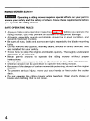
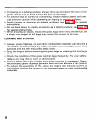
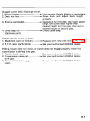
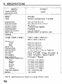
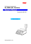
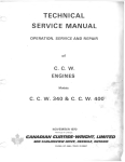
1
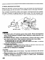
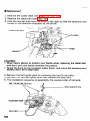
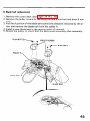
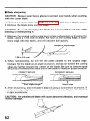
Thank you for purchasing
a Honda riding mower.
This manual covers the operation and maintenance
riding mower, type SA (side discharge).
of the Honda HT-R3811
Honda Motor Co., Ltd. reserves the right to make changes at any time without
notice and without incurring any obligation.
No part of this publication
may be reproduced
without
written
permission.
This manual should be considered a permanent part of the riding mower and
should remain with the riding mower when sold.
Pay special attention
to statements
preceded by the following
words;
A DANGER:
Indicates severe personal
structions
are not followed.
injury or loss of life will result if in-
M&m
Indicates a strong possibility
life if instructions are not followed.
of severe personal injury
CAUTION:
instructions
NOTE:
l
l
Indicates a possibility
are not followed.
Gives helpful
of personal
injury
or equipment
or
loss
of
damage if
information.
Honda riding mowers are designed to give safe and dependable service if
operated according to instructions.
Read and understand
this Owner’s Manual before operating the riding
mower. Failure to do so could result in personal injury or equipment
damage.
If a problem should arise, of if you have any questions
consult an authorized Honda riding mower dealer.
about the riding mower
It is illegal in some areas to operate a gasoline engine without a U.S.D.A.
qualified spark arrester; check local laws and regulations. You can purchase
an optional spark arrester for this riding mower from your authorized Honda
Power Equipment dealer.
HONDA
MOTOR
CO., LTD. 1986,
ALL RIGHTS RESERVED
CONTENTS
1.
2.
3.
4.
5.
6.
7.
8.
9.
10.
11.
2
...........................................................
SAFETY INSTRUCTIONS
COMPONENT IDENTIFICATION
. ................
.................................
CONTROLS ..............................................................................
PRE-OPERATION CHECKS .........................................................
..............................................................
OPERATION ................
l
Starting the engine ...............................................................
.............................................................................
l
Mowing
.
Stopping the engine .............................................................
.
High altitude operation ...........................................................
.......................................................
TRANSPORTING/STORAGE
MAINTENANCE
........................................................................
................................................................
TROUBLESHOOTING
.....................................................................
SPECIFICATIONS
. ...........
WIRING DIAGRAM ........................................................
WARRANTY SERVICE ...............................................................
3
7
10
15
23
23
26
30
31
32
38
55
58
59
60
1 m SAFETY INSTRUCTIONS
WARNING
LABEL LOCATIONS
I
PASSENGERS.
GMAXIMUM SAFE OPERATING ANGLE
10 DEGREES.
(17% GRADE)
10’MAX.
#REDUCE SPEED WHEN TURNING OR
OPERATING ON SLOPES.
GSTOP ENGINE BEFORE REMOVING GRASS
CATCHER OR CLEANING DISCHARGE CHUTE
#KEEP ALL SHIELDS AND SAFETY DEVICES
IN PLACE.
GKEEP PEOPLE AND PETS AT A SAFE DISTANCE
WHILE OPERATING.
I
RIDING MOWER SAFETY
w
Oberating a riding mower requires special efforts on your part to
ensure your safety and the safety of others. Know these requirements before
you operate the riding mower.
SAFE OPERATING
l
l
l
l
l
l
l
l
l
l
l
RULES
Always make a pre-operation
inspection (page 15) before you operate the
riding mower; you may prevent an accident or equipment damage.
All parts, especially guards and shields, should be in good condition, and
securely fastened in place.
Be sure all nuts, bolts and screws are tight; especially the blade mounting
bolts.
Do not remove any guards, warning labels, shields or safety devices; they
are installed for your safety.
Know how to stop the engine and blades quickly. Thoroughly
understand
operation of all controls.
Never permit anyone to operate the riding mower
without
proper
instructions.
Do not allow passengers to ride on the mower or any of its attachments.
Children should not be permitted to operate this riding mower.
Because of the danger of carbon monoxide poisoning, do not run the engine
indoors.
To prevent serious injury, never put your hands or feet under the cutter
deck.
Do not operate the riding mower while barefoot. Wear sturdy shoes or
boots and clothing that is not loose.
Be alert. Do not operate the riding mower when you are tired, ill or under
the influence of alcohol or drugs.
Mow only in daylight or good artificial light.
Watch out for and avoid rocks, roots, holes and other obstacles.
If you hit an object, stop and inspect the riding mower; fix any damage
before you operate the mower again.
Replace damaged, worn or broken parts immediately.
Do not operate near the edge of a ditch or an embankment.
l
l
l
l
l
l
BEFORE MOWING
l
l
l
l
l
Before mowing, always clear the lawn of stones, sticks and other debris.
These objects could be thrown out by the spinning blades and cause an injury or equipment damage.
Select a safe operating speed (gear position) for the area to be mowed.
5th gear should be used only while driving to and from the storage area.
Always ensure that the area in front of and behind the riding mower is clear
of people, pets and debris before starting.
Be very careful when you operate the riding mower in Reverse.
Do not mow in Reverse unless it is absolutely necessary.
OPERATION
l
ON SLOPES
This riding mower is intended for use on relatively flat terrain. Do not use on
sloped surfaces exceeding 10 degrees (I 7% grade). This angle may be further reduced by the condition and type of surface.
Maximum
safe operating
angle
0”MAX
MAXIMUM
IO” (17%
GRADE)
5
l
l
l
l
l
If mowing on a sloping surface, always drive up and down the face of the
grade. Never turn or drive across the face of the slope.
To prevent loss of control or overturning,
always reduce speed and exercise extreme caution when operating on sloping or uneven surfaces.
Avoid turning or stopping on sloping surfaces; see page 28 for special
instructions.
Do not back down or rapidly accelerate up a sloping surface; see page 28
for special instructions.
When mowing on slopes, empty the grass bags when they are half full. On
a slope, the weight of full bags may cause the mower to tip over.
CLEANING
l
l
l
l
l
AND STORAGE
Leaves, grass clippings, oil and other combustible
materials can become a
fire hazard. Be sure to keep the engine compartment,
the upper cutter deck
surfaces and the belt and pulley areas clean.
Stop
the engine
before
removing
the grass
bags
or cleaning
the discharge
chute.
Check the condition of the grass catcher bags frequently.
For your safety,
replace any bag that is worn or deteriorated.
Always empty the grass catcher bags when mowing is completed. D,amp,
decomposing
grass clippings generate heat and can become a fire hazard.
To reduce
the
possibility
cool before storing
materials.
of fire,
the mower
allow
the engine
in an enclosed
and exhaust
system
space or near combustible
to
2. COMPONENT
STEERING
ENGINE
IDENTIFICATION
WHEEL
SWITCH
AIR INTAKE
LEVER
\
I
DISCHARGE’CHUTE
BRAKE‘
PEDAL
\
WARNING
BUZZER
7
POWER
TAKE-OFF
DECK HEIGHT
ADJUSTING
L
CUTTER
DECK
/
REAR
Raise
8
BODY
Engine compartment
AIR CLEANER
FUEL’VALVE
PLUG
OIL DRAIN PLUG
(LOCATED
ON THE FRAME)
OIL FILLER
CAP
9
3. CONTROLS
1. Engine switch
Ewm
Always remove the key from the engine switch
riding mower is unattended to prevent children or unauthorized
starting the engine.
whenever the
persons from
This riding mower is equipped with an automotive type ignition switch, which
controls all the electrical circuits. The switch is located on the right-hand side
in front of the gear shift lever.
Key positions:
“START”
to start the engine
to run the engine after starting
“ON”
“OFF”
to stop the engine.
ENGINE
SWITCH
NOTE: The starter motor will not work unless the shift lever is in NEUTRAL
and the P.T.0 lever is in the OFF (Disengaged) position.
2. Throttle
lever
The throttle
lever controls engine speed from SLOW (idle)
speed). START (CHOKE) is for starting a cold engine.
START
THROTTLE
LEVER
10
to FAST
(max
3. Cutter
deck height
adjusting
lever
This lever is used to raise and lower the cutter deck. To adjust the cutting
height, squeeze the handle lock and then press in and hold the set button.
Raise or lower the lever until the desired cutting height appears on the indicator. At that point, release the set button and the handle lock. Be sure the
handle lock returns to its normal position when released.
Cutting
height:
1 .O, 1.5, 2.0, 2.5, 3.0, 3.5 k-r. (Approx)
CAUTION:
. To avoid damage to the cutter deck,
lawn tractor to and from the mowing
clearance.
l
To avoid damaging or disabling the
tempt to screw the adjusting lever’s
always raise it fully when driving the
area; this provides maximum ground
handle locking mechanism,
set button in or out.
never at-
SET BUTTON
0
+!57
4. Shift lever
This lever is used to select one of the five forward speeds, neutral, or reverse.
The drive clutch automatically
disengages while the lever is being moved. The
clutch will then engage automatically
when put into gear unless the brake
pedal is depressed.
Enml
Do not operate the shift lever on a slope.
CAUTION:
Bring the riding mower to a complete stop before shifting from a
forward speed to reverse, or from reverse to a forward speed. Shifting between forward and reverse speeds while the riding mower is moving can
cause transmission
damage.
When shifting from one forward speed range to another while moving, do not
force the shift lever and do not shift up or down more than one slot at a time.
NOTE: The riding mower
will pull
away from a stop in any speed range.
No shifting is necessary.
5th speed is not recommended
for
mowing but may be used for driving
the riding mower from one area to
another.
’
5. Power Take-Off
(P.T.O.)
lever
This lever engages and disengages the power take-off clutch to drive the blade.
Lever positions:
ON (Engaged) . . . . . . . . . . Blade turns
OFF (Disengaged) . . . . . . . . Blade stops
\
ON (Engaged)
P.T.O.
LEVER
NOTE: An interlock
switch prevents
P.T.O. lever is in the OFF position.
the
engine
from
starting
unless the
6. Brake pedal
Depressing the pedal will first disengage the riding mower drive clutch. As you
continue to depress the pedal, the brake will be applied to stop the riding
mower.
When the clutch
smoothly.
pedal
is released,
the clutch
CAUTION:
Releasing the brake pedal too slowly
and may lead to premature clutch wear.
12
will
automatically
engage
can cause the clutch to slip,
7. Warning
The warning
A.Low
buzzer
buzzer has two functions
oil level alarm (intermittent
which
beeping
are described
below.
sound)
If the oil level falls to a predetermined
level while the engine is running, the
warning buzzer will beep on and off. If this happens, stop the engine immediately, check the engine oil level and add enough of the recommended
oil to bring the level to the upper mark on the dipstick (See page 16).
CAUTION:
Running
engine damage.
the engine
B. Parking brake reminder
(steady
with
insufficient
buzzing
sound)
oil can cause
serious
The warning buzzer will sound continuously
if the transmission is shifted into gear while the parking brake is engaged. If you hear a steady buzz from
the warning buzzer, release the parking brake or shift the transmission into
neutral immediately
(See page 14).
m
Operating
the riding mower with the parking brake set will
result in severe damage to the brake lining, and could lead to a complete
brake system failure.
CAUTION:
If the alarm changes from a steady buzz to an on and off
beep when the parking brake is released, stop the engine immediately,
and check the engine oil level.
PARKING
BRAKE
LEVER
BUTTON
WARNING’
BUZZER
13
8. Parking brake lever
This lever is used to set the brake when the riding
lever fully up until the ratchet locks.
mower
is parked. Pull the
NOTE: The parking brake lever does not operate the automatic
clutch.
Always put the transmission in neutral, or turn off the engine switch before
setting the parking brake. A steady warning buzzer will sound if the parking
brake is engaged while the transmission
is in gear and the engine switch is
ON.
CAUTION:
l
When washing the riding mower, do not allow water to get into the warning buzzer holes.
l
Never park the riding mower on a slope.
To release, pull the lever up slightly
lever while holding the button in.
and press the lever set button,
lower the
Operating the riding mower with the parking brake set will result
E8Nm
in severe damage to the brake lining, and could lead to a complete brake
system failure.
PARKING
BRAKE
\
LEVER
SET BUTTON
WARNING
14
BUZZER
4. PRE-OPERATION
CHECKS
m
To pr’event accidental start-up, remove the engine switch key,
and disconnect
the spark plug cap before performing
the pre-operation
‘
inspection.
1. Make sure the cooling
CAUTION:
overheat.
If the cooling
air intake screens are clean.
air intake
screens
are blocked
the engine
REAR
may
BODY
15
2. Check the engine oil level
CAUTION:
l
l
Engine oil is a major factor affecting engine performance and service life.
Non-detergent oil and 2-stroke engine oil are not recommended.
Running the engine with insufficient
oil can cause serious engine damage.
a. Place the riding mower on a level surface.
b. Lift the rear body, wipe dust and dirt from around the oil filler cap, remove
the cap and wipe the dipstick clean.
c. Insert the dipstick into the oil filler neck, but do not screw it in.
d. Check the oil level shown on the dipstick. If near or below the lower level
mark, fill to the upper level mark with the recommended oil.
Use Honda 4-stroke
motor oil certified
oil, or an equivalent
to meet or exceed
requirements
for service
will show this designation
SAE low-40
high detergent, premium quality
U.S. automobile
manufacturers’
classification
SE or SF (Motor
on the container).
is recommended
for general, all-temperature
oils classified
SE or SF
use.
I
-20
0
40
20
8
-10
10
-30 -20
0
I
I
60
80
I
20
30
100°F
40 “C
UPPER
LOWER
16
LEVEL
LEVEL
3. Check the fuel level
Raise the rear body and check the fuel level.
Refill the tank to the upper level mark if necessary.
Your engine is designed to use any gasoline that has a pump octane
or that
has a research
ocnumber
(R ; M ) of 86 or higher,
tane number of 91 or higher. Gasoline pumps at service station normally
display the pump octane number.
We recommend
that you use unleaded fuel because it produces fewer
engine and spark plug deposits and extends the life of exhaust system
components.
Never use stale or contaminated
gasoline or an oil/gasoline
mixture. Avoid
getting dirt, dust or water in.the‘ fuel tank. Use of a lower octane gasoline
can cause persistent “pinging”
or heavy “spark knock” (a metallic rapping
noise) which, if severe, can lead to engine damage.
CAUTION: If “spark knock” or “pinging” occurs at a steady engine speed
under normal load, change brands of gasoline. If spark knock or pinging
persists, consult your authorized Honda dealer. Failure to do so is considered misuse, and damage caused by misuse is not covered by Honda’s
Limited Warranty.
Occasionally
you may experience
light spark knock while operating under
heavy loads. This is no cause for concern, it simply means your engine is
operating efficiently.
After
refueling,
be sure to tighten
the fuel tank cap firmly.
UPPER
LEVEL
17
Rwlm
l
l
l
l
l
Gasoline is extremely flammable and is explosive under certain conditions.
Refuel in a well!ventilated
area with the engine stopped. Do not smoke or
allow flames or sparks in the area where the engine is refueled or where
gasoline is stored.
Do not overfill the fuel tank (there should be no fuel in the filler neck). After
refueling, make sure the tank cap is closed properly and securely.
Be careful not to spill fuel when refueling. Spilled fuel or fuel vapor may ignite. If any fuel is spilled, make sure the area is dry before starting the
engine.
Avoid repeated or prolonged contact with skin or breathing of vapor. KEEP
OUT OF REACH OF CHILDREN.
GASOLINES
CONTAINING
ALCOHOL
If you decide to use a gasoline containing alcoh.ol (gasohol), be sure it’s octane
rating is at least as high as that recommended by Honda. There are two types
one containing ethanol, and the other containing methanol. Do
of “gasohol”:
not use gasohol that contains more than 10% ethanol. Do not use gasoline
containing
methanol
(methyl or wood alcohol) that does not also contain
cosolvents and corrosion inhibitors for methanol. Never use gasoline containing more than 5% methanol, even if it has cosolvents and corrosion inhibitors.
NOTE:
l
Fuel system damage or engine performance problems resulting from the use
of fuels that contain
alcohol
is not covered
under the warranty.
Honda cannot endorse the use of fuels containing methanol since evidence
of their suitability is as yet incomplete.
l
Before buying fuel from an unfamiliar station, try to find out if the fuel contains alcohol, if it does, confirm the type and percentage of alcohol used. If
you notice any undesirable operating symptoms while using a gasoline that
contains alcohol, or one that you think contains alcohol, switch to a
gasoline that you know does not contain alcohol.
18
4. Check the air cleaner elements
1. Raise the rear body.
2. Remove the two wing nuts to remove the air cleaner cover and air cleaner
elements.
If the elements
are dirty, follow
AIR CLEANER
the cleaning
procedure
described
COVER
WING
AIR CLEANER
on page 39.
NUTS
ELEMENTS
5. Check brake lining wear
Inspect brake lining condition
every time the riding mower is used.
Firmly set the parking brake, and then check the position of the brake wear indicator. If the indicator is near the wear limit, take the riding mower to
an Authorized Honda Power Equipment Dealer for repair.
CAUTION:
Under no circumstances
the brake lining is at the service limit.
PARKING
BRAKE
should
the riding
mower be operated
if
LEVER
WHEEL
BRAKE WEAR
INDICATOR
19
6. Deck belt, primary
belt and blade belt inspection
1 Wear or damage
1. Lower the cutter deck as far as it will go with the cutter deck height adjusting lever.
2. Inspect both belts for wear and damage. If the belts are worn or damaged,
replace them according to the instructions
on pages 47-50.
n Blade belt tension
1. Move the P.T.O. lever to the ON (Engaged) position.
2. Raise the cutter deck as far as it will go with the cutter deck height adjusting lever.
3. If the index mark on the tensioner arm aligns with or goes inward past the
wear indicator on the cutter deck, adjust the belt tension according to the
instructions
on page 47.
BLADE
BELT
CUTTEd
DECK
DECli
INDEX
WEAR
20
PRIMARY
BELT
CUTTER
DECK
BELT
MARK
INDICATOR
7. Check the battery
Raise the rear body,
trolyte level.
remove
the battery
The electrolyte
level must be maintained
lines on the side of the battery.
cover and check the battery
between
elec-
the upper and lower level
If the electrolyte
level is low, remove the battery filler caps and carefully
distilled water to the upper level line.
add
EEm
. The battery
gives off explosive gases; keep sparks, flames and cigarettes
away. Provide adequate ventilation when charging or using batteries in an
enclosed space.
. The battery contains sulfuric acid (electrolyte).
Contact with skin or eyes
may cause severe burns. Wear protective clothing and a face shield.
- If electrolyte gets on your skin, flush with water.
- If electrolyte gets in your eyes, flush with water for at least 15 minutes
and call a physician immediately.
l
Electrolyte is poisonous.
- If swallowed,
drink large quantities of water or milk and follow with milk
of magnesia or vegetable oil and call a physician.
. KEEP OUT OF REACH OF CHILDREN.
CAUTION:
. Use only distilled water in the battery. Tap water will shorten the service life
of the battery.
l
Filling the battery above the UPPER LEVEL line may cause the electrolyte to
overflow,
resulting in corrosion to engine or nearby parts. Immediately
wash off any spilled electrolyte.
21
8. Adjust the seat position
1.
2.
3.
4.
Raise the rear body.
Disconnect the 2-pin connectors.
Loosen the four seat mounting nuts.
Move the seat to a position that allows you to reach all controls easily and
comfortably.
5. Tighten the seat mounting nuts securely. Be sure to re-connect the 2pin
connectors.
2-pin
SEAT
CONNECTORS
MOUNTING
9. Check the tire pressure
CAUTION:
Improper ‘inflation
may lead to premature tire
exceed the manufacturer’s
maximum tire pressure specification.
Check the tire pressure with an air pressure gauge.
Pressure: Front . . . . . 1 .O kg/cm* (14.2 psi)
Rear . . . . .0.7 kg/cm2 (9.96 psi)
22
failure.
Never
5. OPERATION
Starting
the engine
Exhaust gas contains poisonous
carbon monoxide.
Never run
ram
the engine in an enclosed area. Be sure to provide adequate ventilation.
1. Raise the rear body, turn the fuel valve ON and close the rear body.
REAR
BODY
2. Sit on the seat and check that the parking brake lever is set, the transmission
is in neutral and the P.T.O. lever is in the OFF (Disengaged) position.
3. Move the throttle lever to the START (CHOKE) position.
NOTE:
throttle
When the engine
to SLOW.
is warm or the air temperature
is high, move the
START
(CHOKE)
23
4. Turn the engine switch to START.
CAUTION:
Do not use the starter motor for more than 5 seconds. If the
engine fails to start, release the key, and wait at least 10 seconds before
operating the starter motor again.
5. After the engine starts, let the engine switch return to ON.
6. After the engine warms up, move the throttle lever to the SLOW position.
SLOW
24
7. Seat safety switch operation
check.
1. Move the P.T.O. lever to ON (Engaged).
Rise off the seat - the engine should stop immediately.
2. Return the P.T.O. lever’to OFF (Disengaged) and restart the engine.
Release the parking brake and place the shift lever in the 1st speed
range.
While driving slowly,
rise off the seat - the engine should stop
immediately.
CAUTION:
Perform this check on level ground,
never on a slope.
25
Mowing
mm
understand
Before operating
this riding
mower
the safe operating rules. See page 4.
you
should
read
and
CAUTION:
In tall grass, first mow with the cutter deck fully raised (3% in);
this will expose any hidden obstacles. When you are sure the area is
completely cleared, re-mow at the desired height.
NOTE:
For best results,
wait
until
1. Set the cutter deck height adjusting
26
the lawn is dry before
mowing.
lever to the desired cutting
height.
2. Move the throttle
lever to the FAST position.
CAUTION:
When mowing over rough ground or on hillsides, select the gear
that will give a safe ground speed when the engine is operating at full throttle.
-,
START
CHOKE
FAST
SLOW
\
J
NOTE: The riding mower can be operated at intermediate throttle settings if
desired, but always maintain sufficient engine speed for good pulling power
and efficient blade operation. Use the shift lever to select the desired driving
speed range.
3. Move the P.T.O. lever to the ON (Engaged)
position.
/
\
ON (Engayed)
\
OFF
(Disengaged)
/
27
4. Move the shift lever to select the desired gear position.
engage automatically
in about one second.
The clutch
will
CAUTION:
If clutch engagement occurs immediately
or takes longer than
one second, have the riding mower serviced by your HONDA dealer.
l
l
Be sure the area behind the mower
obstacles before backing up.
Operate the mower at low speed until
operating characteristics.
UPHILLSTARTING
rnml
However,
is clear of people,
you become familiar
pets and other
with
all of its
PROCEDURE
If possible, avoid stopping the riding mower while driving
if it is necessary to stop, follow this special procedure:
uphill.
A. Set parking brake.
B. Apply pressure to the brake pedal.
C. Move the throttle lever to mid range.
D.Shift the transmission to 1st gear position.
E. Release the brake pedal.
F. Wait until the clutch engages.
G.Then release the parking brake lever.
EwlMl
riding
riding
28
If the parking brake lever is released before the brake pedal, the
mower may roll downhill before the clutch engages. This may cause the
mower to tip over.
5. Cutting
E%zm
surface.
Patterns
These cutting patterns are only recommended
See safe operating rules page 4.
for a flat, level lawn
0 In a small area
First make 2 or 3 turns in a clockwise
continue cutting in the reverse direction.
0/ 0
JJ,
direction;
then turn
around
and
,7‘,
0 In a large area
The first round of cuts is the key to making a neat finish. First, make 2 or 3
turns in a clockwise direction. As you reach the center of the area, turn to
the right and continue cutting in a counterclockwise
direction until you
have finished the upper half of the area. Cut the grass in the remaining half
in a counterclockwise
direction.
29
Stopping
the engine
0 In an emergency;
Turn the engine switch OFF.
0 In.normal use;
(1) Move the P.T.O. lever to
OFF (Disengaged).
(2)
(3)
(4)
(51
ON kqaged)
/
OFF
1Disengaged)
Move the shift lever to the Neutral position.
Set the parking brake.
Turn the engine switch OFF.
Raise the rear body, turn the fuel valve OFF and close the rear body.
\
REAR
30
\
BODY
I
High altitude operation
At high altitude, the standard carburetor air-fuel mixture
rich. Performance
will decrease, and fuel consumption
will be excessively
will increase.
High altitude performance
can be improved by installing a smaller diameter
main fuel jet in the carburetor and readjusting the pilot screw. If you always
operate the riding mower at altitudes
higher than 6,000 feet above sea
level, have your authorized
Honda Riding Mower dealer perform these carburetor modifications.
Even with suitable carburetor jetting, engine horsepower
will decrease approximately
3.5% for each 1,000 foot increase in altitude. The affect of
altitude on horsepower
will be greater than this if no carburetor
modification is made.
CAUTION: Operation of the riding mower at an altitude lower than the carburetor is jetted for may result in reduced performance, overheating, and
serious engine damage caused by an excessively lean air/fuel mixture.
31
6. TRANSPORTING/STORAGE
Transporting
Transport
the riding mower
suitable tie down points.
on a flat,
level trailer
or pick-up
Turn the fuel valve OFF and set the parking brake lever.
Tie the riding mower down securely,
using the tie down
below.
truck,
points
with
shown
CAUTION: To avoid damaging the tie-rods, be careful not to put the rope
around or near them when securing the front end.
FRONT
REAR
PROPER
TIE-DOWN
_
POINTS
Spilled fuel may ignite. To avoid fuel and oil spillage, keep the,
riding mower level when transporting.
mm
CAUTION: Do not pull the’riding mower behind any other vehicle, and do
not use the riding mower to push another vehicle.
Preparation for storage
CAUTION: If the riding mower has
been running, the engine will be very
hot; allow to cool before proceeding.
The following
steps should be taken
to protect the riding mower whenever it will be stored for longer than
30 days.
1. Drain all gasoline from the fuel tank
into an approved
gasoline
container.
32
Turn the fuel valve ON, loosen the carburetor drain screw, and drain the fuel
into an approved gasoline container. After draining tighten the drain screw
securely.
lmm
conditions.
DRAIN
Gasoline is extremely
flammable and explosive under
Do not smoke or allow flames or sparks in the area.
certain
SCREW
2. Change the engine oil (see page 40).
NOTE: If the riding mower will be stored for longer than 3 months, raise the
rear body and remove the spark plug and pour three tablespoons
(approximately
1 oz.) of clean motor oil into the cylinder.
Place the P.T.O. lever in the OFF position and the shift
tion. With the parking brake applied, lower the cutter
Reaching from the rear of the mower, grasp the primary
slowly pull it toward you to turn the engine. Reinstall
lever in the N posideck to the bottom.
belt at point A, and
the spark plug.
CAUTION:
Be sure to wear heavy gloves when pulling the’primary
belt. If
the riding mower has been running, the engine will be very hot. Allow it to
cool before proceeding.
33
3. Remove the battery and store in a cool, dry place. Recharge it once a
month.
4. Remove the cutter deck:
4-l. Lower the cutter deck and be sure the P.T.O. lever is in the OFF position.
Turn the front wheels all the way to the left, and then remove the belt
stopper.
BELT
4-2. Remove the
transmission.
primary
belt
from
the
pulley
DECK
on the
underside
STOPPER
of the
BELT
CAUTION:
When the cutter deck is removed, the return spring will cause the
deck height adjusting lever to snap unward when the release button is pressed. Hold the lever firmly, and carefully return it to the UPPER position after
removing the deck.
34
4-3. Remove the 7 mm lock pin collar and washer from the P.T.O. clutch rod.
4-4. Remove the four 14 mm lock pins and washers from the right and left of
the cutter deck.
~~
P.TE
ROD
,,,
~
WASHERLOCK
PIN 7 mm
\COLLAR
/
CUTTERDECK
4-5. Remove the front deck arms from the frame body by removing
lock pins and washers.
WASHER
4-6. Disengage the cutter
side to side.
the two
(2)
deck from the rear deck arms by moving
it from
35
4-7. With the steering
right and back.
CAUTION:
the muffler
removal.
wheel all the way to the left, pull the dutter deck to the
Be careful to avoid hitting
with the cutter deck during
5. Turn the cutter deck upside down. Clean the underside of the deck with
water, and dry thoroughly.
6. For longer service-and greater efficiency,
keep the underside of the mower
housing clean and free of accumulated grass clippings by washing it down
with a hose after use and/or cleaning it with a wire brush and scraper.
Remove any rust and apply a rust-resistant
paint. Cleaning and rust
prevention are especially important before seasonal storage.
7. Reinstall the cutter deck by reversing the removal procedure.
LOCK
PIN 14 mm
LOCK
PIN 7 mm
8. Store the riding mower on a level surface in a dry, dust-free area with the
parking brake lever set.
9. Cover the riding mower to keep out dust.
10. Check tire air pressure regularly during storage and inflate if necessary.
36
Removal from storage
1. Check the battery electrolyte
level (see page 21). Fully recharge the battery, and install it in the riding mower.
2. Remove the spark plug and check that it is clean and properly gapped (see
page 42).
Turn the engine a few revolutions with the starter motor before reinstalling
the spark plug.
3. Thread the spark plug in as far as possible by hand, then tighten it l/8 to
l/4 turn further with the plug wrench.
4. Check the engine oil level (see page 16).
5. Fill the fuel tank, and start the engine by following the starting instructions
(see page 23).
NOTE: If the cylinder
up; this is normal.
was coated with
oil, the engine will
smoke at start
37
7. MAINTENANCE
l
l
l
Shut off the engine and set the parking brake before performing
any
maintenance.
To prevent accidental
start-up,
remove the engine switch
key and
disconnect the spark plug cap.
The riding mower should be serviced by an authorized
HONDA dealer
unless the owner has proper tools and service data and feels he is
mechanically
qualified.
CAUTION:
maintenance
may,damage
Use only
genuine
Honda
parts or their
equivalent
for
or repair. Replacement parts which are not of equivalent quality
the riding mower.
Periodic inspection
and adjustment
of the Honda HT-R381 1 is essentia! if
high level performance
is to be maintained.
Regular maintenance
will also
ensure a long service life. The required service intervals and the kind of
maintenance t6 be performed are described on the following page.
ENGINE
KEY
SWITCH
SPARK
38
PiUG
CAP
MAINTENANCE
SCHEDULE
Air cleaner
Parking
operation
brake
Battery
electrolyte
Tire
pressure
Feul
tank
Front
Fuel
Valve
Engine
Check
filter
cable
axle
level
Check
level
clearance
and
shroud
0
12)
0
(2)
0
and
gravity
0
c-3
Clean
0
Check-Adjust
0 12)
Grease
0
Check
(Replace
line
fins
0
Check
Check
and
Throttle
NOTE:
buzzer
(2)
0
if necessary)
(2)
Check-Readjust
0 (2)
Clean
0 12)
(1) Service
the air cleaner
more frequently
when
used in dusty
areas.
(2) These items should
be serviced
by an authorized
Honda
dealer,
unless
mechanically
proficient.
(3) For professional
commercial
use, log hours of operation
to determine
the
owner
proper
has
maintenance
proper
tools
and
IS
intervals.
39
1. Engine oil change
NOTE: Drain the
complete draining.
oil while
the engine
is still
1. Raise the rear body.
2. Remove the oil filler cap and the drain
suitable container.
3. Retighten the dr‘ain bolt securely.
warm
plug,
to assure rapid
and drain
and
the oil into a
NOTE: Before refilling the crankcase, check the operation of the Low Oil
Level Alarm. Remove the spark plug cap, shift the transmission
into neutral
and turn the ignition key to the ON position. The warning buzzer should beep
on and off; if it does not beep, take the riding mower to an authorized Honda
riding mower dealer for repair.
4. Refill to the upper level mark on the dipstick
(see p. 15). Tighten tl 78 oil filler cap securely.
with
OILsFILLER
OIL CAPACITY:
1.1 Iz (1.2 us
qt)
the recommended
CAP
UPPER
LOWEil
oil
LEVEL
LEVEL
‘.
-REAR
OIL
DRAIN
WHEEL
BOLT
CAUTION: Used motor oil may cause skin cancer if repeatedly left in contact
with the skin for prolonged periods. Although this is unlikely unless you handle used oil on a daily basis, it is still advisable to thoroughly wash your hands
with soap and water as soon as possible after handling used oil.
NOTE: Please dispose of used motor oil in a manner that is compatible with
the environment.
We suggest you take it in a sealed container to your local
service station for reclamantion.
Do not throw it in the trash or pour it on the
ground.
40
2. Air cleaner service
A dirty air cleaner will
carburetor
malfunction,
frequently when operating
restrict air flow to the carburetor.
To prevent
service the air cleaner regularly.
Service more
the riding mower in extremely dusty areas.
Never use gasoline or low flash point solvents for cleaning the air
WMiQ
cleaner element. A fire or explosion could result.
CAUTION:
will result.
Never run the engine without
1. Raise the rear body.
2. Remove the wing nuts and the air
cleaner cover. Remove the elements
and separate them. Carefully check
both elements for holes or tears and
replace if damaged.
3. Foam element: Clean in warm soapy
to dry
rinse and allow
water,
thoroughly.
Or clean in high flashpoint solvent and allow to dry. Dip
the element in clean engine oil and
squeeze out all the excess. The
smoke during
initial
engine will
start-up if too much oil is left in the
foam.
4. Paper element: Tap the element
lightly
several times on a hard
surface to remove excess dirt, or
blow compressed air through
the
filter from the inside out. Never try
to brush the dirt off; brushing will
force dirt into the fibers.
the air cleaner.
Rapid engine wear
WING
NUTS
LtpMtNT
41
3. Spark plug service.
Recommended spark plug:
BPR5ES (NGK)
WlGEPR-U (ND)
To ensure proper engine operation,
and free of deposits.
the spark plug must be properly
gapped
1. Raise the rear body and remove the spark plug cap.
2. Clean any dirt from around the spark plug base.
3. Use a spark plug wrench to remove the spark plug.
SPARK
SPARK PLUG
WRENCH
4. Visually
inspect the spark plug. Discard it if the insulator is cracked or
chipped; Clean the spark plug with a wire brush if it is to be reused.
5. Measure the plug gap with a feeler gauge.
The gap should be 0.7 - 0.8 mm (0.028
- 0.031 in). Correct as
necess;iry by carefully bending the side electrode.
0.7 (0.028
42
0.8 mry
- 0.031
in)
6. Thread the plug in by hand to prevent
cross threading.
7. After a new spark plug has been seated by hand, it should be tightened l/2
turn with a wrench to compress its washer.
If a used plug is being reinstalled,
it should only require l/8 to l/4 turn
after being seated.
CAUTION:
The spark plug must be securely tightened. An improperly
can become very hot and possibly damage the engine.
l
Never use a spark plug with an improper heat range.
l
tightened
plug
43
4. Battery
electrolyte
level check
Raise the rear body, remove the battery cover and check the electrolyte level
in each battery cell. Fill the battery with distilled water to the upper level line.
Never overfill the battery.
Any corrosion around the positive and negative terminals should be washed
off with a solution of baking soda and warm water. Dry the terminals and
retighten the terminal bolts if necessary, then coat the terminals with grease.
BATTERY
COVER
/
y
_The battery gives off explosive gases; keep sparks, flames and cigarettes
away. Provide adequate ventilation when charging or using batteries in an
enclosed space.
l
The battery contains sulfuric acid (electrolyte).
Contact ,with skin or eyes
may cause severe burns. Wear protective clothing and a face shield.
- If electrolyte gets on your skin, flush with water.
8
- If electrolyte gets in your eyes, flush with water for at least 15 minutes
and call a physician immgdiately.
l
Electrolyte is poisonous.
- If swallowed,
drink large quantities of water or miik and follow with milk
of magnesia or vegetable oil and call a physician.
. KEEP OUT OF REACH OF CHILDREN.
l
CAUTION:
l
Use only distilled water in the battery. Tap water will shorten the service
life of the battery.
l
Filling the battery abovi the UPPER LEVEL line may cause the electrolyte to
overflow,
resulting in corrosion to engine or nearby parts. Immediately
wash off any spilled electrolyte.
44
5. Drive clutch
inspection
1. Place the shift lever in the “2” position.
2. Using light pressure, push the clutch arm toward the front of the riding
mower until you feel resistance. At this point the index mark on the clutch
arm should be between the two notches on the clutch cable joint. If the index mark moves to the service limit notch, the clutch disk may be worn
out; consult your authorized Honda dealer.
NOTE: Do not force the clutch arm during this inspection,
dication will result.
CLUTCH
I
ARM
or a false failure in-
CLUTCH
ARM
SERVICE
LIMIT
NOTCH
I
CABLE
JOINT
45
6. Wheel removal
Do not attempt to remove a wheel unless the riding mower is on firm and
level ground.
l
Do not attempt to remove or replace a tire unless you have the equipment
and knowledge to do SD properly.
Block the wheels securely.
l
Front wheel
1. Remove the cotter pin.
2: Jack up the front of the mower and remove the 12 mm wheel hub nut,
washer and the front wheel.
3. Install the front wheel in the reverse order of removal.‘Be sure to use a new
cotter pin and bend it properly as shown.
Rear wheel
1. Remove the cotter pin.
2. Jack up the rear of the mower and remove the 14 mm wheel hub, washer
nut and the rear wheel.
3. Apply a thin coat of grease to the axle (splined portion) before installing the
rear wheel.
4 Install the rear wheel in the reverse order of removal. Be sure to use a new
cotter pin and bend it properly as shown.
[JACK POINTS]
FRONT
COTfER
46
PIN
REAR
.7. Deck belt adjustment/replacement
Never attempt to change a belt while. the engine is running.
mm
Remove the engine key from the ignition and disconnect the spark plug cap to
prevent accidental start up.
CAUTION:
Wear heavy gloves to protect
when working with the cutter blade.
your
hands when replacing
belts or
n Adjustment
1. Set the steering wheel in the straight-ahead position.
2. Move the P.T.O. lever to the ON (Engaged) position.
’ 3. Lower the cutter deck as far as it will go with the cutter deck height adjusting
lever.
4. Loosen the 8 x 16 mm flange bolt, and pull the tensioner pulley outward until the index mark on the tensioner arm aligns with the tension alignment
mark on the cutter deck. Hold the tensioner pulley in place, and retighten
the bolt.
PULLEY
INDEX
MARK -ss
TENS,ONER
AR[
1
TENSION
F!,NGE
ALIGNMENT
BOLT
81r
16 mm
MARK
47
n Replacement
1. Remove the cutter deck (see pages 34 thru. 36).
2. Remove the blade belt (see page 49).
3. Hold the bracket and move the knob to the right so that the tensioner
moves in the direction indicated by the arrow.
TENSIONER
arm
ARM
.EYS
BRACKET
CAUTION:
l
Wear heavy gloves to protect your hands when replacing the blade belt,
and don’t put your hands between the pulleys.
l
Grasp the knob on the tensioner pulley firmly, and return the tensioner arm
slowly; don’t let it snap back.
4. Remove the belt guide plate by removing the two 8 mm bolts.
5. Remove the two belt guide bolts and remove the deck belt.
6. The installation
sequence is essentially the reverse order of removal.
BELT
GUIDE
BOLTS
8 mm
Lh
TENSIONER
DECK
BELT
ARM
Q
BELT GUIDE
PLATE
8. Blade belt replacement
1. Remove the cutter deck (see pages 34 thru. 36).
2. Remove the pulley covers by removing the one 8 mm bolt and three 8 mm
nuts.
3. Pull the A portion of the blade belt toward the direction indicated by the arrow and remove the blade belt from the pulley A.
4. Install a new blade belt in the reverse order of removal.
5. Rotate the pulley to check that the belt moves smoothly after assembly.
COVERS
,p-
8 mm BOLT
BL
49
9. Primary belt replacement
CAUTION:
Wear heavy gloves to protect your hands when replacing
the belt.
1. Remove the cutter deck (see page 34 thru. 36).
2. Remove the primary belt from the pulley on the belt tensioner arm while
pressing out on the arm by hand. Then, remove the primary belt from
the pulley on the engine.
3. Remove the tensioner arm by removing the 10 mm bolt and remove the
primary belt by pulling it out by hand.
4. Install a new primary belt. Install the remaining parts in the reverse order of
removal.
TENSIONER
ARM
TENS10
10 km
50
FLANGE
BOLT
10. Blade inspection,
sharpening
and replacement
Never attempt to change a blade while the engine is running.
cmml
qemove the ignition key from the ignition and disconnect
the spark plug
cap to prevent accidental
start up.
CAUTION:
Always wear heavy gloves to protect
with the cutter blade.
your hands when working
n Blade inspection
1. Remove
the cutter
deck from the riding mower
(see page 34 thru.
36).
2. Inspect the blade for cracks, bends or signs of wear. If the blade is bent,
damaged or badly worn, replace it.
CAUTION:
equivalent.
Use
only
FLAT
0
NEW
Honda
genuide
PART
replacement
OF BLADE
blade
or
their
LIFT
0
LIFT
X
Replace
X
Replace
WORN
OR DAMAGED
If the lift of the blade is worn or
damaged,
the mower cannot cut evenly.
X
Replace
If the blade is bent, the mower
cuts
unevenly
and the blade may interfere
with the cutter deck.
W Blade sharpening
CAUTION:
Always wear heavy gloves to protect
with the cutter blade.
your hands when working
1. Remove the cutter deck (see page 34 thru. 36), and turn it upside down.
2. Remove the blade bolts and the blade.
CAUTION:
To avoid damaging
dressing or resharpening
it.
the blade, be sure to hold it securely
while
3. Maintain the original cutting edge bevel when resharpening or dressing the
blade. Leave a l/64 inch (0.4mm) flat face on the cutting edge; a razorsharp edge will chip easily, and will become dull quickly.
l/64
in IO.4
mm)
4. When resharpening,
do
Instead, file the blade on
edge any farther toward
amounts of material from
CORRECT
m
not file the blade parallel to the original edge.
an angle as shown, and do not extend the cutting
the center of the blade. Be sure to remove equal
each end of the blade to maintain proper balance.
METHOD
INCORRECT
~~~~
,,-,~~~~,~~~~~~~~~~
4
Keep
original
length
METHOD
.:~.i.::..::..:.:~.,;.::,::,~
,(,,.:...,.
;2...a/-a&,-,;1
P
Original
edge
5. After sharpening, test the blade’s balance using a screwdriver
as shown. If
either side dips slightly below horizontal, file that side. Replace the blade if
it dips excessively.
CAUTION:
An unbalanced
mower damage.
blade will cause abnormal
r-l
52
vibration,
and eventual
n Blade replacement
CAUTION:, Always wear heavy gloves to protect
with the cutter blade.
1. Hold the blade firmly,
your hands when working
and remove the blade bolt, washer
BLADE
and blade.
BOLT
BLADE
2. Clean any dirt and grass from around the blade shaft and inside the deck.
3. Install a new blade onto the shaft and secure it with the blade bolt and
washer. Tighten the bolts securely and install the mower deck.
Blade bolt tightening
torque:
4.5-5.5
TORQUE
kg-m (32.55-39.78
ft-lb)
WRENCH
BLADE
53
11. Spark arrester maintenance (optional part)
You can purchase an optional, U.S.D.A. qualified spark arrester from your
authorized
Honda Power Equipment dealer. Spark arrester are required in
some areas; check local laws and regulations before operating your riding
mower.
‘W
The muffler becomes very hot during operation and remains
hot-for a while after the engine stops. Be careful not to touch the muffler
while it is hot. Allow it to cool before proceeding.
CAUTION: The spark arrester must be serviced every 100 hours to maintain its efficiency.
1. Remove the three 6 mm bolts and 8 mm bolt that hold the shift lever guide
stay, and then remove the stay.
2. Remove the two 6 mm bolts from the exhaust pipe tip. Remove the
exhaust
pipe
tip
and
spark
arrester
(be
careful
not
to
damage
the
spark
ar-
rester screen).
3. Use a wire brush to remove carbon deposits from the spark arrester screen.
NOTE:
torn.
Inspect
the spark arrester,
and replace
it if the screen
4. Reinstall all parts in the reverse order of removal.
ARRESTER
54
is broken
or
8. TROUBLESHOOTING
Engine fails to start;
1. No fuel.
2. Shift lever in gear.
3. P.T.O. lever engaged. 4. Spark plug faulty or
improperly gapped.
5. Spark plug wire looseor disconnected.
6. Fuel not reaching
carburetor.
7. Discharged battery
loose terminal.
or -
Engine loses power;
1. Dirty air cleaner elements. 2. Spark plug faulty or
improperly gapped.
3. Engine overloaded.
Engine overheats;
1. Cooling air intake plugged.2. Engine overloaded.
3. Spark plug improperlygapped.
4. Cooling fan damage
b Add fuel.
w Position shift lever in NEUTRAL.
Position blade (P.T.O.) lever in
DISENGAGE.
* Regap plug or replace (see p. 42).
Check spark plug wire.
* Check the position of the fuel valve
(see p. 23). If that’s not the problem.
see your authorized HONDA dealer.
Charge battery or retighten terminal.
(see p. 441.
Clean or replace elements (see p. 41).
) Regap plug or replace. (see p. 42).
w Shift to lower speed.
Clean cooling air ‘intake (see p. 15).
L Shift to lower speed.
Regap plug or replace (see p. 42).
*See your authorized
HONDA
dealer.
55
Erratic operation;
1. Dirty fuel.
2. Dirty air cleaner elements.3. Spark plug faulty or P
improperly gapped.
Excessive vi bration;
1. Loose blade or enginemounting hardware.
2. Blade damaged or out of balance.
Battery will not charge;
1. Dead cell in battery.
2. Loose electrical connec-tions or broken wire.
Uneven mowing;
1. Riding mower speed too fast2. Grass accumulation
inside deck.
3. Dull blade.
4. Tires improperly
inflated.5. Mower not level.
6. Wrong cutter deck height.7. Chute clogged (if equipped with optional grass bag).
56
b See your HONDA dealer.
Clean air cleaner elements (see p. 41).
Regap plug or replace (see p. 42).
Retighten blade bolts or engine
mounting
hardware
to the specified
torque.
Replace blades.
ti Replace battery.
Check connections
and lines.
Shift to lower speed.
*Clean deck inside (see p. 36).
+ Sharpen blade or replace.
Check tire inflation (see p. 22).
-Check
cutter deck mounting.
See your authorized HONDA dealer.
Change to proper height.
Empty grass bag and chute.
Clogged cutter deck discharge chute.
* Use genuire Honda blades or equivalent.
1. Wrong blades
+ Raise deck and adjust deck height
2. Deck too low.
properly.
+ Operate at full throttle. Use lower speed
3. Engine overloaded:
range. Set cutter deck higher than
desired height for first pass, then cut to
desired height on second pass.
4. Grass bags full
* Empty grass bags.
. (Optional part).
Blades do not rotate or stop.
1. Blade belt worn or broken .-Replace
2. P.T.O. lever malfunction
-See
with new belt (see p. 47- 50).
your authorized HONDA dealer.
Riding mower does not move, or clutch does not engage properly when the
transmission is shifted into gear.
+See your authorized HONDA dealer.
1. Faulty clutch assy.
your authorized HONDA dealer.
2. Transmission does not -See
shift gear.
3. Abnormal clutch engage- See your authorized HONDA dealer.
ment.
57
HT-R3811
MODEL
Power products
description code
MABT
ENGINE
Model
Type
GXV340
4-stroke, overhead valve, 1 cylinder
Displacement
Bore and stroke
Ignition timing
Ignition system
Cooling system
Engine oil capacity
Spark plug
337 cm3 (20.6 cu in)
82 x 64 mm (3.2 x 2.5 in)
20” BTDC
Transistorized
magneto
Forced air
1.1 !? (1.2 USqt)
BPR5ES (NGK), WlGEPR-U (ND)
FRAME
Dimensions
Length x Width x Height
Wheel tread
Front
Rear
Wheel base
Cutting width
Cutting height
Dry weight
Tire size
‘Air pressu re
Gear selections
Travel speed (3300 rpm)
First
Second
Third
Fourth
Fifth
Reverse
Fuel tank capacity
Battery
NOTE:
58
Specifications
1535 x 1260 x 1000 mm
(60.4 x 49.6 x 39.4 in)
570 mm (22.4 in)
635 mm (25.0 in)
1100 mm (43.3 in)
970 mm (38.0 in)
1, II/,, 2, 2l/,, 3, 3l/, in. (Approx)
177 kg (390.2 lb)
Front 11 x 4.00 - 5 Rear 16 x 6.50 - 8
Front 1 .O kg/cm2, Rear 0.7 kg/cm2
5 Forward, 1 Reverse
2.4
3.7
5.7
7~0
7.9
2.8
2.0
12V
km/h (1.5 mile/h)
km/h (2.3 mile/h)
km/h (3.5 mile/h)
km/h (4.3 mile/h)
km/h (4.9 mile/h)
km/h (1.7 mile/h)
P (0.53 US gal)
22AH
are subject to change without
’
notice.
BUZZER
CONTROL
UNIT
SEAT
BUZZER
RELAY
CONTROL
RECTIFIER
RELAY
STARTER
RELAY
SWITCH
ITCH
PARKING
SWITCH
BRAKE
COMBINATION
SWITCH
BUZZER
T
PLUG
TAN
OIL LEVEL
SWITCH
MOTOR
RAT7a .‘ERY
ax_
112V MAHI
GROUND
003oz-751-7ooo
11. WARRANTY
SERVICE
Owner Satisfaction
Your satisfaction
and goodwill
are important
to your dealer and to us. All
Honda warranty details are explained in the Distributor’s
Limited Warranty..
Normally,
any problems concerning
the product will be handled by your
dealer’s service department.
If you have a warranty
problem that has not
been handled to your satisfaction,
we suggest you take the following
action:
l
l
Discuss your problem with a member of dealership management.
Often
complaints
can be quickly resolved at that level. If the problem has
already been reviewed with the Service Manager, contact the owner of
the dealership or the General Manager.
If your problem still has not been resolved to your satisfaction,
contact
the Power Equipment
Customer
Relations
Department
of American
Honda Motor Co., Inc.
American
Honda Motor Co., Inc.
Power Equipment
Customer Relations
P.O. Box 50
Gardena, California
90247-0805
Telephone:
(2 13) 604-2400
We will need the following
-
information
inorder
Your name, address, and telephone
Product model and serial number
Date of purchase
Dealer name and address
Nature of the problem
number
Department
to assist
you:
After reviewing
all the facts involved,
you will be advised of what action
can be taken. Please bear in mind that your problem will likely be resolved
at the dealership,
using the dealer’s facilities, equipment,
and personnel, so
it is very important
that your initial contact be with the dealer.
Your purchase
of a Honda product is greatly appreciated
by both your
dealer and Ameri,can Honda Motor Co., Inc. We want to assist you in every
way possible to assure your complete satisfaction
with your purchase.
60
MEMO
61
MEMO
62
MEMO
63
MEMO
64