1
SE/A-Jf S
OW_
'S
UAL
ODEL NO.
_42.252440
WIDTH
TOW
ATTACH
NT
Caution:
Read and follow
all Safety Rules
and Instructions
Before Operating
This Equipment
.
.
.
.
.
Assembly
Operation
Customer Responsibilities
Service and Adjustment
Repair Parts
Sears, Roebuck and Co., Hoffman
i
i
Estates, IL 60179, U.S.A
ii!l!lll
Safe Operation
SAFETY
RULES
for the Tow-Behind
Practices
TRAiNiNG
Never store the equipment
with gasoline
in
the tank inside
of a building
where fumes
may reach an open flame or spark
Allow
the engine
to cool
before
storing
in an
enclosure.
Read
opening
and Service
instructions
carefully.
Be thoroughly
familiar
with the
controls
and
the
proper'
use
of the
equipment,
°
Never' allow children
to operate
Do not allow adults to operate
without proper instruction.
o
Keep
the area
of operation
ctear
persons, particularly small children and pets.
Stop engine and disconnect
spark plug lead
wire
before
cleaning
tines,
removing
obstacles
or making
adjustments
except for
any instructions
which
must be done while
the engine is running_
the machine
the machine
of
all
Never
place
hands
or feet under
or into
rotating
parts or concealed
areas.
Keep
hands
and feet
clearly
away from
tine
elements, belts, pulleys, etc, while engine is
running.
PREPARATION
Check
the fuel
and
lubrication
before
starting the engine
Do not fill the gasoline
tank indoors when the engine is running
or
while the engine
is still hot
Wipe off any
spilled gasoline before starting the engine,
o
e
Tiller Attachment
Wear substantial
while using tiller.
shues
and
Never'
attempt
to make
adjustment
except
on the
engine is running.
Inspect the area to be filled_
Remove glass,
wire, metal objects,
large sticks and stones,
Avoid underground pipes and wiring°
eye
protection
a maintenance
carburetor,
while
Do not run the engine
indoors;
monoxide fumes are dangerous to inhale.
Have a complete
working
knowledge
of your
tractor
and know how to handle your tractor
with a tiller or'other attachment attached.,
Never
operate
guards,
plates
devices in place.
machine
or other
carbon
without
proper
safety
protective
OPERATION
o
Give complete
and undivided
attention
to the
job at hand,
Operate
the tiller
in daylight
or good artificial light,
Personal
injury may result from contact
with
the tines or debris thrown
by this machine,
Therefore,
always stay a safe distance
away
from tines.
=
Stop the tiller'
tUler unattended_
o
Check
parts,
before
engine
each
when
use for loose
leaving
•
Disengage
and tractor
tractor,,
•
Disengage
the Tine Drive Clutch
the tiller engine during transportation to
and from the work area.
MAINTENANCE
or
o
iMPORTANT
and
stop
AND STORAGE
Disconnect
spark
plug wire before
any maintenance adjustment or repair,.
Store
gasoline
in an
container in a cool, dry place,,
Warnings,
Cautions,
and Notes are a means of
attracting
attention
to important
or critical
information in this manual.
LOOK FOR THIS SYMBOL TO POINT OUT
IMPORTANT SAFETY PRECAUTIONS. IT
MEANS-A]TENTION! BECOME ALERT!
YOUR SAFETY IS INVOLVED.
Drive Clutch,
stop tiller
before
getting
off the
Follow
maintenance
instructions
as outlined
in this
manual
and your
Engine
Owners
Manual supplied with the unit.
your
fasteners
the Ttne
engines
approved
making
metal
Keep all nuts, bolts and screws tight.
Keep
machine ingood operating
condition and keep
safety devices in place.
2
Safety and performance
levels can be assured
only by the use of specified
replacement
parts,,
CONGRATULATIONS
onyourpurchaseofa Searstiller. It
hasbeendesigned,
engineered
andmanufactured
to give
youthe bestpossibledependability
andperformance.
Shouldyouexperience
anyproblems
youcannoteasily
remedy,pleasecontactyournearestSearsAuthorized
ServiceCenter.Searshascompetent,
welltrained
technicians
andthepropertoolsto serviceor repairthis
uniL
PRODUCT SPECtRCATIONS
HORSEPOWER:
5,,0 HoP.
DISPLACEMENT:
t 2.57 cu. ino
J
GASOLINE CAPACITY:
Regular
Unleaded
OIL (20 oz. Capacity):
Above 32 F:
SAE 30
Below 32 F:
SAE 5W30
Pleasereadandretainthismanual.Theinstructions
will
enableyoutoassemble
andmaintainyourtillerproperly_
Alwaysobservethe"SAFETY
RULES"_
MODEL
NUMBER
842-252440
SERIAL
NUMBER
DATEOF
PURCHASE
THEMODELANDSERIAL
NUMBER
WILLBE
FOUNDONTHEMODEL
PLATE
ATTACHED
TO
THERIGHTHANDCHASSIS.
YOUSHOULD
RECORD
BOTHSERIAL
NUMBER
ANDDATEOFPURCHASE
ANDKEEPINA
SAFEPLACEFORFUTURE
REFERENCE.
MAINTENANCEAGREEMENT
A Sears Maintenance Agreement is available on this
product_ Contact your nearest Sears store for details.
CUSTOMER
=
•
•
RIESPONSIBILITIES
Read and observe the safety rule&
Follow a regular schedule in maintaining, caring for and
using your Tiller
Follow the instructions under"Customer
H
3 QUARTS
SPARK PLUG (GAP ..030 IN.):
Champion
RJ19LM
TILLING GROUND SPEED:
Approx 2 MPH
TILLING WIDTH:
36 IN.
TILLING TtNE SPEED:
260 RPM
This unit is equipped with an internal combustion engine
and should not be used on or near any unimproved forestcovered, brush-covered, or grass-covered land unless the
engine's exhaust system is equipped with a spark arrester
meeting applicable local or state laws (if any)° If a spark
arrester is used, it should be maintained in effective
working order by the operator.
In the state of California the above is required by law
(Section 4442 of the California Public Resources Cod_),
Other states may have similar laws. Federal laws apply on
federal lands. See your Sears Authorized Service Center
for spark arrester. Refer to the repair Parts section of
this manual for part number.
Responsibilities" and "Storage" sections of this Owner's
Manual
i
LIMITED
ONE YEAR WARRANTY
ON CRAFTSMAN
TILLER
For one year from date of purchase, when this Craftsman Tiller is maintained, lubricated, and tuned up according to the
operating and customer responsibilities instructions in the owner's manual, Sears will repair free of charge any defect in
material or workmanship°
This Warranty does not cover:
Expendable items which become worn during normal use, such as tines, spark plugs, air cleaners and belts.
Repairs necessary because of operator abuse or negligence, including bent crankshafts and the failure to maintain th_
equipment according to the instructions contained in the owner's manual.
If this Craftsman Tiller is used for commercial or rental purposes, this warranty applies for only 30 days from the date
of purchase.
WARRANTY SERVICE IS AVAILABLE BY RETURNING THE CRAFTSMAN TILLER TO THE NEAREST SEARS SERVICE
CENTER/DEPARTMENT iN THE UNITED STATES THIS WARRANTY APPLIES ONLY WHILE THIS PRODUCT IS IN
USE IN THE UNITED STATES
This Warranty gives you specific legal right, and you may also have other rights which vary from state to state
SEARS, ROEBUCK AND CO, D/817 WA, HOFFMAN ESTATES, tL 60179
TABLE OF CONTENTS
Safety Rules ...................
Customer Responsibilities
...............
Warranty ......................
Product Specifications ...............
Accessories ....................
Assembly ........................
2
3
3
3
5
6
Operation ........................
Customer Responsibilities
..........
Service & Adjustments ..............
Storage .................
Troubleshooting
..................
Repair Parts-Tiller
..................
7-10
11-13
14-15
16
17
18-25
aNDEX
E (Cont)
5
8
.12
.........
Oil Level ..............
Oil Type .........
Spark Plug ..........
Starting, ..............
Stopping ............
Storage ..........
9 Repair Parts:
9
Tiller
,13
Engine ..........
9 Rules for Safe Operation
8
o16
S
...........
Accessories .............
Adjustments:
Depth Stake ........
Air Cleaner:
Maintenance
.....
18-20
21-25
2
B
F
Belt:
V-Belt
.............
.14 Fuel:
Cooling System:
Maintenance
.........
Controls:
Choke .............
Tine ................
Throttle ...........
Customer Responsibilities:
Air' Cleaner .........
Cooling System .......
Finish ............
Maintenance Schedule
Muffler ..............
Spark Plug ...........
Transmission ...........
Oil Change .........
Cultivating:
Operation .............
12
..........
7
7
7
....
10
..........
8
E
Engine:
Air Cleaner
............
Cooling System
Fuel Type .................
Lubrication
..........
Carburetor'. ...........
..........
L
Lubrication:
Lubrication Chart .......
Engine ............
12
_12
,13
M
11
13 Muffler:
,13
Maintenance
..........
13
Spark Arrestor .........
_12
O
D
Depth Stake:
Adjustment
Fitling Tank .......
Type ...............
Storage ..........
Finish:
Maintenance
.......
Service & Adjustments:
V-Belt ............
Service:
9
Maintenance Schedule ....
9 Spark Plug:
`16
Gap ..............
Maintenance
.........
`13 Storage:
Fuel System
Tiller .............
12
1
3
9
12
15
OI1:
Level ................
Type ..............
Operation:
Cultivating ...........
Fill Engine with Oil ......
Fill Fuel Tank ...........
Start Engine ..........
Stopping Tines & Engine ....
Tilling ............
Tilling Hints ............
Tine Operation ......
Transporting Tiller ......
Breaking in Your' Tiller .....
4
T
,1t
.12 Tilling:
Operation .........
Tines:
Repair Parts .........
Operation ..........
,13 Transmission:
3
Maintenance
.......
Repair Parts .........
Troubleshooting Chart .....
Transporting ...........
9
12
10 Warranty .............
9
9
9
8
10
10
8
8
10
,t4
11
3
,13
J6
16
7-10
38
8
,'13
20
.17
8
W
3
ACC
THESE ACCESSORIES WERE AVAILABLE WHEN THE TILLER WAS PURCHASED. THEY ARE ALSO AVIALABLEAT MOST
SEARS RETAIL OUTLETS, CATALOG AND SERVICE CENTERS. MOST SEARS STORES CAN ORDER REPAIR PARTS FOR
YOU WHEN YOU PROVIDE THE MODEL NUMBER OF YOUR TILLER
ENGINE
......... ,i, ,,
SPARK PLUG
MUFFLER
AIR FILTER
GAS CAN
ENGINE OIL
STABILIZER
@
................
ii
TILLER MAINTENANCE
BELT
CLEVIS PIN
TINES
HAIR COTFER PiN
O
ACCESSORIES
HILL ROW
AERATOR
DETHATCHER
i
i
i
I
TRACTION/COMFORT
ATTACHMENTS
.............................................................
i
TIRE CHAINS
i
,,
i
WHEEL WEIGHTS
TRACTOR
TILLER
i
30 LB O_y__
5
i
lul
ii
i
iii
u ii IIIIHII
_
,,,,,,,,,,,,
.........
,
,, ,
,
,,,
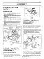
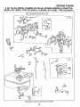
ASSEMBLY
J,rrT,,,,
..................................................................
::: ;:::...................................................
TO REMOVE UNIT FROM
CARTON
-'_
FLOATING
UNPACKCARTON
® Cut from top to bottom all four corners of the carton
and lay panels flat.. (See Fig1)
e Remove lag screw that holds the floating hitch to the
packing skid..
e Disassemble and discard wood top and side carton
supports.
e Remove four Hex Bolts, four Hex nuts, and four Flat
Washers from the hold down Brackets at rear of Tiller
carton.
e Remove two Flat Washers and two Cotter Pins from
rear Axle and save for use when attaching Gauge
Wheels.
e Discard all other packing Hardware and hold down
Brackets_
e Remove Gauge Wheels from Wheel Box
WOOD TOP
SUPPORTS
HO'LD DOWN
BRACKET
ACCESSORY
TILLER WEIGHTS
COTTER
FLAT WASHER
FIG. 2
TO HNSTALL THE TnLLER
(WHEEL) WEHGHT
ACCESSORIES
NOTE: Tiller (Wheel) Weights are not furnished with
Tiller'.. They are an accessory that may be purchased if
required (See Operation section of the manual.)
LAG SCREW
e Remove two Carriage Bolts and Nuts from the front of
each Tine Shield, located approximately 3-1/2 inches
from the front edger (See Fig3)
e Place Tiller (Wheel) Weight on Tine Shield and
secure with long Bolts and Nuts furnished with the
Weights.
ACCESSORY
LONG
WEIGHT
WOOD SIDE
SUPPORTS
WHEEL
BOX
PACKING
SKID
HEX BOLT
HEX NUT
FLAT WASHER
TINE
SHIELD
FIG. 1
TO HNSTALL THE T6LLER
GAUGE WHEELS
ATTACH
GAUGE WHEELS
® Assemble Gauge Wheels onto the Rear Axle with
extended Hub inward and secure with a Flat Washer
and Cotter Pin. (See Fig. 2)
FIG. 3
When R.H (Right Hand) or L.Ho (Left Hand) are used, it
means from a position behind the steering wheel as if
you were seated on the tractor seat and facing forward_
NOTE: We recommend that you remove Mower Deck
before using Tiller
='_--
........................
,_,,, ,J,
,
.................................................
,._L,,LU,, ,J L
J__
J
............
:
OPERATmO
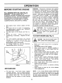
KNOW YOUR TILLER
READ THIS OWNER'S MANUAL AND SAFETY RULES BEFORE OPERATING YOUR TILLFR
Compare the illustrations with your tiller to familiarize yourself with the location of various controls and
adjustments
Save the manual for future reference
............
i,iiii,
RECOIL STARTER HANDLE
,11,,,,,i,
,,11
......................................................................
CHOKE CONTROL
OFF iDLE FAST
LOWER
LIFT HANDLE
THROTTLE CONTROL
.
RAISE
,.
_\\
EXTRA TINE PINS
ENGAGED
TINE CLUTCH LEVER
DEPTH STAKE
DISENGAGED
SUPPORT BRACKET
FLOATING HITCH
GUARD
'DEPTH ADJUSTMENT
TINE SHIELD
TINES
GAGE WHEELS
FIG. 4
TINE CLUTCH LEVER - starts and stops tine
rotation
LIFT HANDLE - selects tilling or transport
position by moving gage wheels
THROTTLE CONTROL- controls engine speed
CHOKE CONTROL - used when starting a cold
engine
FLOATING HITCH - telescoping hitch limits
shock loads to tractor
DEPTH STAKE - controls tilling/cultivating
depth
RECOIL START HANDLE - used to start the
engine
Theoperationofanytillercanresultinforeignobjectsthrownintotheeyes,whichcan
resultinsevereeyedamage.Alwayswearsafetyglassesor eyeshieldsbeforestarting
your tiller and while tilling We recommend wide vision safety mask for over the
spectacles or standard safety glasses°
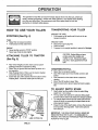
HOW TO USE YOUR TnLLER
TRANSPORTSNG
YOUR TILLER
AROUND THE YARD
STOPPING
(See Fig. 4)
o
TINES
o Raise Tiller to transport position.
o Pull forward on tine clutch lever.
AROUND TOWN
_' Disconnect spark plug wire,
a Drain fuel tank,
ENGINE
•
Move throttle control to "STOP" position.
o Never use choke to stop engine
ATTACHING
TILLER
o
o
•
•
Transport in the upright position to prevent oil leakage.
"1
CAUTION: Before lifting or transporting, allow tiller engine and
muffler to cool. Disconnect spark
plug wire. Drain gasoline from fuel
tank.,
TO TRACTOR
(See Fig. 5)
o
Pull forward on lift handle until it locks in the up
transport posttton.
Rear wheel weights and tire chains can be used if
additional traction is required for tilling.
Place Tiller' on ground level and back up tractor to it
for assembly
Slide Floating Hitch of Tiller over the tractor drawbar
so that the hitch pin holes line up
Insert hitch pin until it extends from the bottom of the
Floating hitch_ Insert hair cotter pin into hitch pin.
1
STARTING TO TiLL
o
•
o
o
o
Raise Tiller to transport position,_
Start Tiller engine and move throttle control to full
speed.
Push rearward on tine clutch lever to start tine
rotation_
Move Tiller lift handle to lower Tiller.
Setect lowest tractor ground speed at tractor engine
idle.
TO ADJUST
o
•
a
o
HITCH PII_
TRACTOR
DRAWBAR
DEPTH
STAKE
Depth stake has five position holes to select tilling
depth from 1 to 5 tnches_
The top stake hole selects the sallowest tilling depth
and the bottom stake hole selects the deepest position.
To change depth remove the hair cotter pin from the
clevis pin which is connecting the depth stake to the
stake support bracket..
Grasp the top of the depth stake, remove the clevis pin
and reposition the drag stake_ Insert clevis pin and
hair cotter pin_
IMPORTANT: THE DRAG STAKE SHOULD NEVER BE
REMOVED FROM THE TILLER IT IS DESIGNED TO
PROTECT THE TRACTOR TRANSAXLE FROM THRUSTING
ACTION OF THE TILLER°
HAIR COTTER PIN
RG. 5
|
8
BEFORE STARTRNG ENGNNE
FiLL ENGINE WiTH OIL (See Fig. 6)
IMPORTANT:
BE VERY CAREFUL NOT TO
ALLOW DIRT TO ENTER THE ENGINE WHEN CHECKING
OR ADDING OIL OR FUEL. USE CLEAN SAE30 WEIGHT
OIL AND STORE IN APPROVED, CLEAN, COVERED
CONTAINERS,. ALL OILS MUST MEET AP,!.. SERVICE
CLASSIFICATION SG. USE CLEAN FILL FUNNELS..
•
o
•
o
•
o
With engine
level,
remove
engine
oil filler
plugo
Fill engine with oil to point of overflowing.
For approximate
capacity
see "PRODUCT
SPECIFICATIONS" on page 3
Tilt tiller
back on its wheels
and then relevel
Check
oil
level,
Refill
to point
of
overflowing
if necessary.
Replace oil filler
plug.
WARNING:
Experience
Indicates
that alcohol
blended
fuels (called gasohol
or using ethanol
or methanol)
can attract
moisture
which leads
to separation
and formation
of acids
during
storage.
Acidic gas can damage the fuel system
of an engine while in storage°
To avoid engine
problems,
the fuel system
should
be emptied
before storage of 30 days or longer.
Drain the
gas tank, start the engine
and let it run until
the fuel lines and carburetor
are empty°
Use
fresh fuel next season.
See Storage section of
this manual for additional
informatiom
Never
use engine
or carburetor
cleaner
products
the fuel tank or permanent damage may occur°
CAUTION:
Fill to bottom
of gas
tank
filler
neck_
Do not overfill
Wipe off any spilled oil or fuel.
Do
not store, spill or use gasoline near
open flame
TO START ENGINE (See Fig. 7)
For cold
weather
operation
you should
change
oi! for easier
starting
(See "OIL
VISCOSITY
CHART"
tn the
Customer
Responsibilities section of this manual).
To change
engine
oil, see the
Responsibilities section in this manual
Customer
CAUTION:
Keep
the starting
tine Clutch
Lever in
"OFF"
position
when
engine.
o
=
OIL
o
LEVEL
OIL
FILLER
PLUG
FIG. 6
Fill fuel tank.
Use fresh,
clean,
regular
unleaded
gasoline_
(Use of leaded gasoline
wilt increase
carbon and lead oxide deposits
and reduce
valve
life),
Do not use old
gasoline
from last season to avoid starting
probtems.
Make
sure spark
plug
wire is properly
connected.
Place throttle control in "FAST" position,
Place choke control
in "CHOKE"
position
if
the engine is cold_ A warm engine may not
require choking to start.
Grasp
starter
handle
with one hand.
Pull
rope out slowly until engine reaches start of
compression
cycle
(rope will pull slightly
harder at this point)°
Pull rope with a rapid, continuous,
full arm
stroke.
Keep a firm grip on starter handle
and let rope
rewind
slowly.
Do not let
starter handle snap back against starter..
e
When engine starts,
move
engine to the "RUN" position.
=
Move throttle
control
position
Allow engine to warm
before engaging tines,
o
ADD GASOLINE
In
to
choke
desired
up for
control
on
running
a few minutes
NOTE:
If at a high altitude
(above 3000 feet)
or in cold
temperatures
(below
32 F), the
carburetor
fuel mixture may need to be adjusted
for best engine performance°
See Service and
Adjustment section of this manual
OPERATJO
if the soil is extremely hard and dry, it may be
desirable to cross till an area at shallow depth first,
then till in the direction of planting rows on the
second pass at the final depth
O
SPARK
PLUG
CHOKE
THROTTLE
CONTROL
RECOIL STARTER
HANDLE
•
Where possible, we recommend tilling In a pattern
similar to that shown in Fig. 8. Make tile first pass,
then skip a space equal to the width of the tiller, and
make the return pass. Then till the skipped area.
Tilling in this pattern will enable you to maintain
better control° If the passes were made side-by-side,
the tractor and tiller would tend to pull toward the
tilled (soft) side.
o
Check ground moisture: If you can make a ball in
your hand out of ground to be tilled, do not till sotl if
too wet. This causes lumps which are difficult to
work up.
o
When operating for the first time, proceed slowly and
carefully until you become familiar with the proper
method of operating the tiller°
In soil that has ttlled the year before, select the
tilling depth at which the tiller engine runs
comfortably and does not stall or pull down. Lower
depth for additional passes If greater depth is desired°
Whenever working multiple passes, go perpendicular to
the previous tilling direction.
in cases where the soil is too hard to get proper
penitration or if tilling action causes Tiller to hop or
bounce, it wilt be necessary to purchase a set of Tiller
(Wheel) Weights.
FUG. 7
BREAKUNG
YOUR TILLER
Break-in your belts, pulleys and the control before you
actually begin tilling
e Start engine, tip tines off ground by pressing handles
down and engage fine control to start tine rotation.
Allow tines to rotate for' five minutes
o Check line operation and adjust if necessary. See
'_TINEOPERATION CHECK" in the Service and
Adiustments section of this manual.
=
o
,,
TnLLING
o
o
=
The most efficient tillage is obtained when Tiller
Engine ts operated at full throttle. The sound of the
Tiller Engine will tell you. When Tiller' Engine is
lightly loaded, raise Gauge Wheels to increase tilling
depth. If Engine seems to be overloaded or stalls out,
lower Gauge Wheels for shallower' tilling..
Operate Tiller Engine at full throttle and operate
tractor in slowest forward speed, with tractor engine
at idle speed or just above idle. You will soon learn
the proper combination of tilling depth and speed for
good tillage.
Soil conditions will determine how deep Tiller can
penetrate on the first pass In extremely hard
ground, severa! passes may be necessary to till to a
depth of 6 inches. While in soft ground, Tiller may
penetrate to a depth of 6 inches in the first pass.
TILLING
CULTIVATING
Your tiller may be used for cultivating which required
a minimum of two (2) inches of soll penetration.
Set depth stake so the Tiller will penetrate soil to a
depth of 2 to 3 inches. The Tiller Engine should be
run at full throttle except when cultivating small
plants. A slower engine is necessary to prevent
burying the plants.
o
o
HINTS
t
IMPORTANT OPERATING HINTS
--
=
-3
=_
NOTE: The following is a general guideline of tilling,
but may vary depending upon soil conditions.
0 010 0
0 Ol© ©
00lO
O
C IC 0
in _soil,
the tiller should be started in the
shallowest depth position and lowered one position at a
time after each pass in each
positiOnr
| 0
FIG.
8
FiG. 9
O
©
0
L
i,i
i, i
i1,,i,i, ,i
CUSTOM
i
i
PO
ILITIES
.........................................
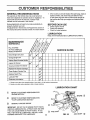
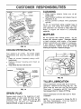
GENERAL RECOMMENDATIONS
•
The warranty on this Vehicle does no! cover items that
have been subjected to operator abuse or negligence, To
receive full value from the warranty, operator must
maintain unit as instructed in this manual_
Once a year you should replace the spark plug, clean or
replace air filter, and check tines and belts for wear,
A new spark plug and clean air filter assure proper airfuel mixture and help your engine run better and last
longer,
BEFORE EACH USE
Some adjustments will need to be made periodicalIy to
properly maintain your unit
All adjustments in the Service and Adjustments section of
this manual should be checked at least once each season,
°
•
,,
Check engine oil level
Check tine operation,
Check for loose fasteners,
LUBRICATION
Keep unit well lubricated (See "LUBRICATION CHART")_
MAINTENANCE
SCHEDULE
FILL IN DATES
AS YOU COMPLETE
REGULAR SERVICE
SERVICE
DATES
Check Engine Oil Level
Change Engine Oil
Inspect Spark Arrester Muffler
Inspect Air Screen
Check and Clean Air Cleaner
Replace Air Cleaner Cartridge
Clean Engine Cylinder Fins
Replace Spark Plug
Lubricate Tiller
Chaincase Lubrication
1 - Change more often when operating under a heavy load or in high ambient temperatures
2 - Service more often when operating in dirty or dusty conditions
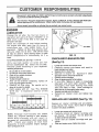
LUBRICATION
(_
REFER TO CUSTOMER RESPONSIBILITIES
"ENGINE SECTION,"
(_)
REFER TO CUSTOMER RESPONSIBILITIES
'q'ILLER LUBRICATION SECTION,"
(_
GENERAL PURPOSE GREASE
IMPORTANT: DO NOT OIL OR GREASE PIVOT POINTS
VISCOUS LUBRICANTS WILL ATTRACT DUST AND DIRT
THAT CAN CAUSE WEAR ON PIVOT POINTS, IF YOU
FEEL 'THEY MUST BE LUBRICATED, USE ONLY A DRY
POWERED GRAPHITE TYPE LUBRICANTS,
CHART
(_) TINE SHAFT
11
FiG. 10
AXLE SHAFT
(_)
,,,i ii,,i
i i,=,1,1
,,i
CUSTOM
=ill
IBmLITI
Ill
Disconnect spark plug wire before performing any maintenance
to prevent accidental starting of engine.
(except carburetor adjustment)
Prevent fires! Keep the engine free of grass, leaves, spilled oli, or fuel. Remove fuel from tank
before tipping unit for maintenance. Clean muffler area of all grass, dirt and debris.
Do not touch hot muffler or cylinder fins as contact may cause burns°
ENGINE
OIL
DRAIN
PLUG
LUBRiCATiON
Change
the oil after
the first
two hours of
operation
and every 25 hours thereafter
or at
least
once a year if the tiller
is not used for
25 hours in one year_
Ct_eck the crankcase
oil level before starting
the engine
and after
each fine (5) hours of
continuous
use.
Add SAE30
motor
oil or
equivalent
Tighten oil filler plug securely each
time you check the oil level.
SAE 5W-30 motor
oil may be used to make starting easier in areas
where
temperature
is consistently
30 F or
lower
OIL FILLER
PLUG
DIL LEVEL
FiG. 12
CHECKANDCLEANAIR
FILTER
TO CHANGE ENGINE OIL (See Ftgs 1! and 12)
Only
use high
quality
service
classification
SG
viscosity
grade
according
operating temperature.
o
o
=
•
=
•
•
o
(See Fig.13)
oil rated
with
API
Select the oil's SAE
to your' expected
a
e
Be sure tiller is on level surface.
Oil will drain more freely when warm
Catch oil in a suitable container_
Remove drain plug.
Tip tiller forward to drain oil.
After oil has drained
completely,
replace oil
drain plug and tighten securely.
Remove
oil filler
plug,.
Be careful
not to
alJow dirt to enter the engine
Refill
engine
with oil,
See "FILL ENGINE
WITH
OIL'
in Operation
section
of this
manual
o
o
,b
=
o
•
o
SAE VISCOSITY GRADES
Loosen two screws and remove cover.
Carefully
remove
pre-cleaner
and wash in
liquid detergent and water_
Squeeze dry in a clean cloth
Saturate
in engine
oll
Squeeze
in clean
absorbent cloth to remove att excess oil.
Carefully remove cartridge°
Clean by tapping gently on flat surface.
If very dirty, replace or wash in nonsudsing
detergent
and warm water solution.
Rinse
thoroughly
with water
flowing
from
mesh
side until water is clear.
Allow cartridge
to
stand and air dry thoroughly before using.
Reinstall cartridge and pre-cleaner.
Reinstall
air cleaner
cover and tighten
two
screw=
REPLACE AiR CLEANER
"_
._o"
;€ "i_':,
,
o" -_ _o_.__ 40.
ec,"
,,............
,
,
.z0'
,to"
o"
. _o..
_,
TEMPERATURE
RANGE ANTICIPATED
BEFORE
Replace
air cleaner
cartridge
and pre-cleaner
every twenty
five hours,
more often if engine
is used in very dusty conditions°
0o' ,pp_ too"
4_,
NEXT OIL CHA_,G, _
FUG. 11
NOTE:
Although
multi-viscosity
oils (5W30,
10W30 etc)
improve starting
in cold weather,
these
multi-viscosity
oils
will
result
in
increased
oil consumptioon
when used above
32°F.
Check
your
engine
oil level
more
frequently
to avoid
possible
engine
damage
from running low on oil
(See Fig. 13)
e
•
12
Loosen two screws and remove cover,.
Carefully
remove air cleaner
cartridge
and
pre-cleaner
Be carefult
Do not allow dirt
or debris to fall into carburetor.
install
new air cieaner
cartridge
and precleaner.
Clean and replace cover, tighten two screw.
U
CUSTOME
ES
....................................................
,i
CLEANnNG
SCREW
o
o
Clean
engine,
wheels,
finish,
etc. of all
foreign matter°
Keep finished
surfaces
and wheels
free of
all gasoline, oil, etc.
Protect
painted
surfaces
with automotive
type wax.
We do not recommend
using a garden hose to
clean
your
unit unless
the muffler,
air filter
and carburetor
are covered
to keep water out,
Water
in engine
can result
in a shortened
engine life.
MUFFLER
Do not operate
tiller without
muffler,
Do not
tamper with exhaust system,
Damaged mufflers
or spark arresters
could create
a fire hazard,
Inspect
periodically
and replace
if necessary.
If your engine is equipped
with a spark arrester
screen
assembly,
remove
every 50 hours for
cleaning and inspection° Replace if damaged°
DUAL AtR CLEANER
FIG. 13
COOLING
SYSTEM (See Fig. 14)
Your engine
is air cooled..
For proper engine
performance
and long life keep your engine
clean,
e Clean
air screen
frequently
using a stiffbristled brush,
o
®
Remove
blower
housing
and
necessary_
Keep cylinder fins free of dirt and chaff..
CYLINDER
clean
as
FINS
BLOWER
TRANSMISSION
AIR SCREEN
FiG. 15
TILLER LUBRiCATiON
Check transmission
oil level after first 5 hours of
operation.
Remove Oil Fill Plug (Fig, 15).. Oil
Level must be even with the Plug Hole (with
Tiller level).
If necessary,
add Oit, Use SAE30
Non-Detergent Motor OiL Replace Oil Fill Plug,
RG. 14
SPARK PLUG
Replace
spark plugs at the beginning
of each
tilling
season
or after every
50 hours of use,
whichever
comes first,
Spark plug type and gap
setting
is
shown
in
"PRODUCT
SPECIFICATIONS" on page 3 of this manual.
Check
transmission
oil level after each 10 hours
of operation°
NOTE:
It is not necessay
to change
this Tiller
Transmission.
If for any
must be changed, Oil capacity is 22 oz.
13
the Oil tn
reason
it
ii
1,1,,
i1,1,,, ,i
,
,111
C
.....
,,,i,,,,,,i,
iiii1,,,,,i, i
ADJUSTMENTS
i, I ,
i,,11,1,,
i
.... i,ii I
i
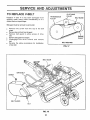
TO REPLACE V-BELT
TRANSMISSION
PULLEY
Replace
V-belt
if it has been damaged
from
slipping
under heavy loads considerably
or if it
shows cracks or' frayed edges.
i
,
i,,111,1,,i,
,
CLUTCHING
PULLEY
BELT GUIDE
Belt guard must be removed to service belt,,
o
o
o
Remove the screw from the top of the belt
guard.
Remove hex nut from front of guard°
Remove belt guard to allow access of drive
belt.
•
•
Remove belt guide from engine,,
Disengage
tine drive
control
bell
o
Reverse the above
of new belt,
procedures
and
for
ENGINE
PULLEY
remove
BELT ROUTING
installation
FnG. 17
BELT GUIDE
DRIVE BELT
SCREW
BELT GUARD
NUT
F!IG. 16
14
ADJUSTMENTS
J
u,,,,
ENGINE
THROTTLE UNKAGE
TOADJUSTCARBURETOR
, ....
11.IROTTLESTOP
(See Fig. 18)
The carburetor
has been preset
at the factory
and
adjustment
should
not be necessary°
However,
minor adjustments
may be required
to
compensate
for dirrences
in fuel, temperature,
altitude
or load.
if the carburetor
does need
adjustment, proceed as follows.
In general,
turning the
needle
valve
in
(clockwise)
decreases
the supply of fuel to the
engine
giving
a leaner
fuel/air
mixture.
Turning
the needle valve out (counterclockwise)
increases
the supply
of fuel to the engine
giving a richer fuel/air mixture.
IMPORTANT:
DAMAGE TO THE NEEDLES AND
THE SEATS IN CARBURETOR
MAY RESULT IF
SCREWS ARE TURNED IN TOO TIGHT
PRELiMiNARY
®
e
SETTING
Air cleaner assembly must be assembled to
the carburetor
when
making
ca, buretor
adjustments
With
engine
off,
turn
needle
valve
in
(clockwise)
closing it finger tight and than
turn valve
out (counterclockwise)
t-1/2
turns°
FINAL SETTING
®
Start
engine
and allow
to warm
for five
minutes.
Make final adjustments
with engine
running
and gearshift
control
lever
in
"NEUTRAL" position.
iDLE RPIVI ADJUSTMENT
e
To adjust idle RPM, rotate
throttle linkage
counterclockwise
and hold against stop while
adjusting
idle speed adjusting
screw to
obtain 1750 RPMo Release throttle linkage.
ACCELERATION
e
TEST
Move throttle
control lever from "SLOW" to
"FAST"
position.
If engine
hesitates
or
dies,
turn
needle
valve
out
(counterclockwise)
1/8 turn.
Repeat test and
continue to adjust, if necessary, until engine
accelerates smoothly.
High speed stop is factory adjusted.
damage may result
IDLE SPEED
ADJUSTING
/
SCREW
NEEDLEVALVE
RG.
18
IMPORTANT: NEVER TAMPER WiTH THE ENGINE
GOVERNOR, WHICH IS FACTORY SET FOR PROPER
ENGINE SPEED OVER-SPEEDING THE ENGINE ABOVE
THE FACTORY HIGH SPEED SETTING CAN BE
DANGEROUS. tF YOU TH1NK THE ENGINE-GOVERNED
HIGH SPEED NEEDS ADJUSTING, CONTACT YOUR
NEAREST SEARS SERVICE CENTER WHICH HAS
PROPER EQUIPMENT AND EXPERIENCE TO MAKE ANY
NECESSARY ADJ USTM ENTS
TBNE CARE
o
For best results--Tine Blades should be kept reasonably sharp. The Tine Blade can be sharpened on a
grinding wheel Do net attempt to sharpen Tines while
mounted to Tiller_
SPARE TBNE PnNS
The Tiller Drive components are protected from damage by a (Shearable) Tine Pin located in the Tine
Assembly used to drive them and hold them in the
proper location. Should the Tine Assemblys strike or
pick up a large hidden object or become jammed, the
Tine Pin will break and the Drive Line will not be
damaged.
WARNING: SHUT OFF (DISENGAGE) THE
TINE CLUTCH LEVER, THE TILLER
ENGINE, AND THE TRACTOR ENGINE
BEFORE MAKING ANY REPAIRS.
A number of extra Tine Pins have been included with
the Tiller_ They are located in the Tiller Stake
Support Bracket. Additional Tine Pins can be obtained
from your nearest Sears Service Center/Departmento
Do not adjust or
Tine Pins are designed to be loose fit. Do not attempt
to use a Pin larger or harder than that provided as
original equipmenL
STORAGE
Immediately
prepare
your til+er for storage
at
the end of the season or if the unit will not be
used for 30 days or more+
CAUTION:
Never
store
the
tiller
with gasoline
in the tank
inside
a
building where fumes may reach an
open flame
or spark.
Allow
the
engine to cool before storing in any
enclosure+
TBLLER
Q
a
o
o
o
Clean
entire tiller' (See "CLEANING"
in the
Customer
Responsibilities
section
of this
manual)_
Inspect
and replace belts, if necessary
(See
belt replacement
instructions
in the Service
and Adjustments section of this manual).
Lubricate
as shown
in the
Customer
Responsibilities section of this manual+
Be sure that all nuts, bolts and screws are
securely
fastened+
Inspect moving parts for
damage,
breakage
and wear.
Replace
if
necessary.
Touch
up all rusted
or chipped
paint
surfaces; sand lightly before painting.
ENGINE
FUEL SYSTEM
NOTE:
Fuel
stabilizer'
is an acceptable
alternative
in minimizing
the formation
of fuel
gum deposits
during storage+
Add stabilizer to
gasoline
in fuel tank
or storage
container.
Always follow
the mix ratio found on stabilizer
container
Run engine at least 10 minutes after
adding
stabilizer
to allow the stabilizer
to reach
the carburetor.
Do not drain the gas tank and
carburetor if using fuel stabilizer.
ENGINE OiL
Drain oil (with engine warm) and replace
with
clean
oil (See "ENGINE"
in the Maintenance
section of this manual)+
CYLINDERS
o
o
o
=
OTHER
•
o
=
o
IMPORTANT:
IT iS IMPORTANT TO PREVENT
GUM DEPOSITS FROM FORMING IN ESSENTIAL FUEL
SYSTEM PARTS SUCH AS THE CARBURETOR, FUEL
FILTER, FUEL HOSE, OR TANK DURING STORAGE.
ALSO, EXPERIENCE INDICATES THAT ALCOHOL
BLENDED FUELS (CALLED GASOHOL OR USING
ETHANOL OR METHANOL) CAN ATTRACT MOISTURE
WHICH LEADS TO SEPARATION AND FORMATION OF
ACIDS DURING STORAGE ACIDIC GAS CAN DAMAGE
THE FUEL SYSTEM OF AN ENGINE WHILE IN STORAGE.
=
o
•
e
Remove spark plug+
Pour' one ounce of oil through
spark plug
hole into cylinder+
Pull starter handle
slowly several times to
distribute oil
Replace with new spark plug+
Do not store gasoline
from one season to
another:
Replace your gasoline can if your can starts
to rust
Rust and!or
dirt in your gasoline
will cause probiems
If possible,
store
your
unit indoors
and
cover it to give protection
from dust and
dirt+
Cover
your unit with a suitable protective
cover that does not retain moisture+ Do not
use plastic.
Plastic cannot breathe which
allows condensation
to form and will cause
your unit to rust+
IMPORTANT:
NEVER COVER TILLER WHILE ENGINE
AND EXHAUST AREAS ARE STILL WARM+
Drain the fuel tank+
Start the engine and let it run until the fuel
lines and carburetor are emptyo
Never use engine or carburetor cleaner products
in the fuel tank or permanent damage may occur..
Use fresh fuel next season..
16
TROUBLESHOOTI
PROBLEM:
Probable Cause ---_-
Possibte Remedy
WiLL NOT START OR HARD TO START
No gasoline in Fuel Tank ----_
Choke not set propedy
Throttle Control not set properly
Choked improperly, flooded Engine
Dirty Air Cleaner
Loose Spark Plug Wire
Spark Plug dirty or improper gap
Water in gasoline or otd fuel
improper Carburetor adjustment
Clogged Fuel Tank
Fill tank with gasoline
Place Choke Control in "CHOKE" position
Place Throttle Control in "FAST" position
Move Choke control to "RUN" position, place Throttle Control In
"FAST" position and pull Starter several times to clear out gas
Remove to inspect, replace if dirty
----_. Make sure Spark Plug Wire is seated properly on Spark Plug
-----_- Replace Spark Plug and adjust gap
Drain Fuel Tank and Carburetor, use fresh fuel and replace Spark
Plug
-- Make necessary adjustments
-------_- Remove and clean
ENGINE MISSES
OR LACKS POWER
Engine overloaded --------*-Set Depth Stake and Wheels for shallower tilling
Partially plugged Air Cleaner
-- Remove and clean or replace
Clean Air Screen
Dirty Air Screen
Spark Plug dirty, improper gap or wrong type
Replace Spark Plug and adjust gap
Ofl in gasoline ----_. Drain and refill gas Tank and Carburetor
Improper Carburetor adjustment
Make necessary adjustments
Clogged Fuel Tank -----_. Remove and clean
Poor compression
Major Engine overhaul
ENGRNE OVERHEATS
Low oil level or dirty oil
Dirty Air Screen
Dirty Engine
Partially Plugged Muffler
Improper Carburetor adjustment
EXCESSIVE
-----_-----_.
_,
---_
----_
Add or change oil
Clean Air Screen
Clean Air screen Clean Cylinder Fins, Air Screen and Muffler area
Remove and clean Muffler
Adjust Carburetor to richer position
BOUNCE AND DIFFICULT
Wheels and Depth Stake incorrectly adjusted _
Ground too dry and hard --.
HANDLING
Adjust Wheels and Depth Stake
Moisten ground or wait for more favorable soil conditions
SO_L BALLS UP OR CLUMPS
Ground too wet _
Wait for more favorable soil conditions
ENGINE RUNS WELL BUT TILLER WON'T MOVE
Tine Control not engaged _
V-Belt off of pulleys _
ENGINE
Engage Tine Control
Check V_Belt
RUNS WELL BUT LABORS WHEN TILLING
Tilling too deep ----*.
Throttle Control not properly adjusted _
Carburetor not adjusted properly _
Adjust Depth Stake
Check Throttle Control setting
Check Carburetor adjustment
17
_Ts
86"
6°-.41 jq
m
75C jZ,
>
m
24
12
59
68
/
_B7
88
_--40
>
t
?
11
40
-1-
4
-@
-t
J
r
rIll
|
I
12/-_ _.-";.<
&3
67 _
-'"%'.
1
12
\
62
7'_/'''-.
44
82
€_O
18
x"_
69
14
O/
-
"'43
0
81
m
r-
67
_..1"5
17,
19
Css
"84
46_
54
16
27
r
m
5O
65,
37
c
c@
\
2E
%,I
57
46
64
38"
/
51
o
/
45
47
67
50
[
52
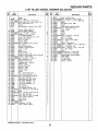
REPAIR PARTS
5 HP TDLLER--MODEL
Ref.
No.
Part
Ku_ber
Description
NUMBER
R_.
I
Engine
2 20295
Guide - Belt
3 *GM-180083! Bolt, 5/16"-18 x I-I/2" Hex HD
4 kGM-115321 Screw, 5/16"-18 x 5/16" Cup Pt..Set
5 i11154
Key, Square 3/16" x 2"
6 20176
Pulley
7 20171
Flag Assembly, Caution (incl. #60)
I
I
4
I
I
I
I
9 i19860
Spring, Depth Extension
10 20701
Hitch Bracket Assembly
11 *GM-180079 Bolt, 5/16"-18 x I" Hex HD
12 _GM9413447 Locknut - 5/16" - 18 Hex
13 20679
Lift Handle Assembly
14 15683
Screw, Self-Tapping 1/4" x I/2"
15 20257
Ring - I/4 Push On
16 20135
Ring, Retainer
17 20184
Pulley, Input
18 *GM-180120 BOlt - 3/8"-16 x 3/4" Hex HD
19 20183
Cap, Push On
20 20180
Clutch Rc_IAssembly
21 20167
Bracket, Clutch Control
22 203{>B
Lever, clutch
23 20341
Spacer
24 20170
Grip, Handle
25 20162
Bracket, Guide - LH
26 20134
Bracket, Belt Guide & Idler Mounting
27 *GM9413534 Lmcknut - 3/8"-16 Hex
28 _GM-180022 Bolt, I/4"-20 x I" He)(HD
29 20185
Key, Woodruff Ha. 61
30
._0163
Bracket, Guide - RH
31 20119
Transmission - Complete
32 20160
Chassis, Left
33 20186
Spring, Extension
34 20159
Chassis, Right
35 20179
Bracket, Idler
36 11496
Pulley, Zdler
V-Belt
37 2O187
Nut - I/4"-20 Hex Lock
38 4119
39 20936
Tine Shield Assembly - LH
40 _GM-180077 BOlt, 5/16"-18 x 3/4" Hex HD
41 20112
Rear Guard Assembly - LH
42 20118
Connectimj Pin, Rear Guard
43 20113
Rear Guard Assembly - RH
44 20094
Tine & Hub Assembly - RH
45 20088
Tine & Hub Assembly - LH
46 10070
Pin, Clevis
iHair Cotter Pin
47 3430
48 20935
iTine Shield Assembly - RH
49 *GM-180126 iBolt, 3/8"-16 x 1 I/2" Hex HD
Wheel
50 20918
51 _GM-180179
iBolt - I/2"13 X 1 3/4" Hex HD
52 2067O
.Pivot Axle Assembly
53 *GM-126PP7 Bolt, 3/8"-16 x 3/4" Carriage
54 20725
Strap Frame Extensioa
55 3433
Pin, clevis
56 20690
Stake, Drag
57 _GM-41_5363 Jasher
58 *GM-120380 Lockwasher I/4 Medo
59 20316
Plate, Fender Support
1
1
10
25
I
1
I
I
I
I
3
I
1
I
I
2
I
1
10
7
I
I
I
1
I
I
1
1
I
8
1
9
1
2
I
I
1
4
2
I
4
2
_ndard
itardware-
Ref.
No,
60
61
62
63
64
65
66
67
68
69
70
71
842.252440
Part
HL{_ber
l)escriptim
20941
Decal, Caution Flag
*GM-18012B Bolt - 3/B"-16 x 1 3/4" Hex HD
*GM-120389 Washer - 1/2" x 1 1/4" X ,083 Flat
20342
Spacer
20704
Belt Gaurd (incl. #69)
14306
Washer
20691
Strap-Frame
Extension Brace
*GM9414074 Nut - I/2='-13Hex Lock
20938
Decal, Danger
20942
Decal
5713
Spacer
15200
Washer
Bolt - 1/2"-13 X 1" Hex HD
7732*GM-180173
13780
Anchor - Spring
74 20706
iRod - Lift Anchor
75 *GM-120123 Pin - 1/8 x 1 I/4" Cotter
76 206B8
iRod - Lift
73' 19649
iAnchor - Adjustment
78 *GM-120396 iWasher - 17/32 x 1 1/16 x .095 Flat
79 *GH-124934 iNut - I/2-20 Hex Jam
80 *GH-456151 iWesher - 13/16 x 1 I/2 x .134 Flat
81 20481
iPin - Hair Cotter
B2 7974
Spacer
83 *GM-44560B BoLt-I/2-13 x 5 I/2 Hex HD
84 *GM-12635B iBolt-5/16-18 X I" Carriage
85 20932
Bracket-Wheel Weight Support
86 20940
Decal-Danger
87 5236
Pin-Locating
3341
PirrHair Cotter
NP 20711
Manual - Owner's
1
I
4
2
2
I
2
1
I
Purchased Locatly
19
Qty.
R_ I.
1
1
!
I
I
1
1
3
2
1
1
2
1
1
I
6
1
1
1
2
I2
I6
2
1
2
2
I
I
1
1
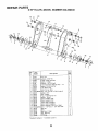
REPAIR PARTS
5 HP TiLLER--MODEL
24
NUMBER
842.252440
20
14
24
2t
17
14
11
12
14
23
19
21
24
25
9
23
13
12
7
6
5
Ref.
Part
N_m_aer'
I 20344
2 *STD541431
3 20123
4 20122
5 4119
6 20120
7 20136
8 20127
9 20121
10 *GM-186676
11 20125
12 20124
13 [20130
14 20129
15 20132
16 20128
17
20133
18 20131
19 20135
20 *STD522512
21 20137
22 20145
23 20156
24 i20138
25 t22462
*Standard
Description
Dust Cap
Locknut, 5/16"-18
Flange & Bearing Assy
Gasket,
Flange
Locknut, I/4"-20 HexO
Drive Housing & Bearing Assy - LH
Gasket, Drive Housing
Tine Shaft Assy
Idler Pulley Assy
Bolt, Hex I/4"-20 x 5/8" Grade 8
Washer, Felt
Seal, Rubber'
Plug, Transmission OIL
Washer', Thrust
Chain Assembly #40
Chafn Assembly #40
Input Shaft Assembly
Idler
Shaft Assembly
Rh_,
Retainer
5/8. Dia. shaft
Bolt
- 1/4"-20
x 1 1/4" Hex Head
Bearing
Seal
Bearing,
Flange
Cap, Bearing
"O_'Ring
Hardware
= Purchased
Locally
2O
11
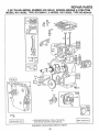
REPAIR PARTS
5 HP TILLER--MODEL
NUMBER 842.252440
ENGINE--BRIGGS
& STRATTON
MODEL NO.130202, TYPE NO.3286-01,
& MODEL NO.135202, TYPE NO.0304-01
26
7.
33
230
46
2t9
220
(_22
358 GASKET SET l
* REQUIRES SPECIAL TOOLS TO INSTALL
SEE REPAIR INSTRUCTION MANUAL,
Assemblies
include
all parts shown in frames.
21
1019 LABEL KIT]
REPAIR PARTS
5 HP TILLER--MODEL
NUMBER 842.252440
ENGINE--BRIGGS
& STRATTON
MODEL NO.130202, TYPE NO.3286-01, & MODEL NO.135202, TYPE NO.0304-01
24
68
O
74
655
@
!
t200
37.3
65
:3O5
©
"(Q16
37
,I, REQUIRES SPECIAL TOOLS TO INSTALL
SEE REPAIR INSTRUCTION MANUAL
Assemblies
include all parts shown in frames,,
22
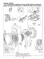
REPAIR PARTS
5 HP TILLER--MODEL
NUMBER 842.252440
ENGINE--BROGGS & STRATTON
MODEL NO.130202, TYPE NO.3286-01, & MODEL NO.135202, TYPE NO.0304-01
121 CARBURETOR
OVERHAUL KiT l
124
2O8
191
527
204
526
916
Assemblies include
al! parts shown in frames,
23
tt
REPAIR PARTS
5 HP TILLER--MODEL
NUMBER 842.252440
ENG|NE--BRIGGS
& STRATTON, MODEL NO. 130202, TYPE NO. 3286-01
REF.
NO.
PART
NO.
1
2
395990
297565
Note:
3
5
299819
211542
7
8
_272157
294178
9
10
11
12
_27549
94621
66578
_270080
13
14
15
16
18
19
20
21
22
Cyiinder Assembly
Bushing-Cylinder
Requires Special Tools
For Installation
Seal-Oil
Head-Cylinder
Gasket-Cylinder
Head
Breather-Valve
Chamber
Gasket-Valve Cover
_270125
_270126
( 005" Thick)
Gasket-Crankcase
94221
93369
94387
492088
Note:
297602
297603
Note:
294606
66768
93032
REE
NO.
26
(,009" Thick)
Screw-Cylinder
Screw-Cylinder
Plug-Pipe
Crankshaft
Head
Head
PART
NO.
298982
298983
298984
298985
27
28
Screw-Breather
Mtg
Grommet-Brea
Tube
Gasket-Crankcase
( 015" Thick, Standard)
Gasket-Crankcase
26026
298909
298908
29
299430
Note:
Ring Set-Piston
(Standard)
Ring Set-Piston
(.010" O S,)
Ring Set-Piston
( 020" O S )
Ring Set-Piston
(030" O.S)
Lock-Piston Pin
74
75
81
90
95
93758
224061
222263
492611
93499
96
97
223793
490048
Pin Assy,-Piston
(Standard)
Pin Assy,.-Piston
108
118
121
124
127
127A
491177
231533
494624
93357
220352
223789
Crankpin Bore-Order
No,_390459
149
152
26336
260575
153
154
490589
93527
163
271935
492927
490075
94094
(,005" O,S,)
Rod Assy,-Connecting
For Connecting Rod
With ,020" Undersize
221890
221876
Dipper-Connecting
Rod
Lock-Connecting
Rod
Screw
32
92296
211119
261044
Screw-Connecting
Valve-Exhaust
Valve-Intake
260552
26478
222443
93312
260642
212733
Spring-Intake Valve
Spring-Exhaust
Valve
Guard-Flywheel
Retainer-Valve
Spring
Tappet-Valve
Gear-Cam
180
181
190
Gasket-Carb
Mtg,
Housing-Rewind
Starter
200
201
202
203
204
205
208
209
216
219
220
222
223
224
223886
262280
262270
280720
222962
231520
262279
262282
262359
494845
221551
490649
223455
93491
227
230
256
300
304
490374
222450
223813
393615
490169
33
34
35
Cover Assy.-Crkcse
Bushing-Crkcse,
Cover
Requires Special Tools
For Installation,
Seai-Oi_
36
37
40
45
46
52 _=271936
55
299431
56
297229
222698
298904
Fiywheet-Magneto
Key-Flywheel
Piston Assy,
(Standard)
57
58
490179
66884
298905
Piston Assy
(O10"O S,)
Piston Assy.
59
6O
65
490653
490652
(, 020" OS )
Piston Assy
(.030" OS)
66
399671
67
68
70
71
394897
63770
298799
394506
Housing-Starter
Bali-Clutch
Ratchet-Rewind
Washer-Clutch
Retainer
73
221923
Screen-Starter
298906
298907
PISTON RING SETS:
Note: For Chrome Piston
Ring Set (Standard
Size) Order Part No
299742
PART
NO.
30
31
To Replace Crankshaft
Gear Pin, Order Part
No 23097&
Plug-Oil Filler
Screw-Crankcase
REF
NO.
DESCRiPTiON
Cover Mounting Sere
94666 Stud
90832 Lockwasher
Note:
23
24
25
DESCRIPTION
295871
94128
Rod
Head
Washer-Spring
Lock-Screw
Carburetor Assembly
Screw-Throttle Valve to
Shaft
Throttle-Carburetor
Shaft and LeverThrottle
Valve Group-Choke
Valve-Needle
Carburetor Overhaul Kit
Screw-Hex
Head
Plug-Welch
Plug-Welch
(Mixing Chamber)
Spring-Needle Valve
Sprlng-Throttie
Adjustment
Screw Assy,.
Screw-Machine
R& Hd
Gasket-Air Cleaner
Mounting
Pulley-Rewind Starter
(Includes 63" Long
Rope)
Spring-Rewind Starter
Rope-Rewind Starter
(63" Long)
Insert-Starter Handle
Handle-Rewind
Starter
Screw-Stamped
Steel
Housing Mtg. Sere
Clutch Assy,,Rewind Starter
Included in Gasket SetPart N0,397145
DESCRIPTION
Screw-Hex
Clutch
Starter
191 _e272410
Tank Assembly-Fuel
Cap-Fuel Tank
Screw-Fuel Tank
Mounting Sem
Gasket-Fuel Tank
Mounting
Gulde-Ait
Link-Governor
Link-Throttle
Crank-Bell
Bushing-Gov, Lever
Screw-Shoulder
Rod-Control
Spring-Governor
Link-Choke
Gear-Governor
Washer-Thrust
Bracket-Control
Lever-Gov. Control
Rivet-Governor Control
Lever Mounting
Lever Assy,-Governor
Washer-Gov Lever
Crank-Bell
Muffler-Exhaust
Housing-Blower
Pulley
tnctuded in Carburetor Overhaul KitPart No,. 494624
24
REPAnR PARTS
5 HP TiLLER--MODEL
NUMBER 842.252440
ENGINE--BRiGGS
& STRATTON, MODEL NO. 130202, TYPE NO. 3286-01
REF
NO,
PART
NO,
305
93158
306
307
221511
93490
308
333
335
337
346
356
358
221512
397358
93414
492167
93705
398808
397'145
363
373
19069
92987
383
392
89838
262328
394
414
=270026
220982
432
433
434
436
467
221377
93265
210959
93141
280715
526
94409
527
528
223786
231550
REF
NO.
PART
NO.
Screw-Blower Housing
Mounting
Shield-Cylinder
Screw-Cylinder Shield
Mounting Sam
Cover-Cylinder
Head
Armature Assembly
Screw-ArmatureMtg.
Plug-Spark
Screw-Sere
Wire-Ground
Gasket Set
529
67838
535
536
542
491435
494279
93572
552
231079
562
592
92613
231082
608
611
390463
391813
Flywheel Puller
Nut-Hex.
613
93935
Wrench-Spark
Plug
Spring-Fuel Pump
Diaphragm
Diaphragm
Washer
614
93306
6'!5
616
93307
231077
Retainer-E-Ring
Crank-Governor
621
634
396847
271853
Switch-Stop
Washer-Throttle
643
280737
(Foam)
Retainer-Foam
Element
665
222598
676
393757
Insert-Spring
Anchor
Deflector-Exhaust
679
270382
(Side Outlet)
Washer Choke Shaft
DESCRIPTION
Cap-Spring
Pin-Diaphragm Cover
Cover-Diaphragm
Screw-Diaph
Cover
Knob-Control
Screw-Tank
Bracket
Mounting Sere
Clamp-Breather
Tube-Breather
Tube
DESCRIPTION
Grommet-Breather
Tube
Efement-Air Cleaner
Air Cleaner Kit
Screw
Bushing-Governor
Crank (t/4" ID,,)
Bolt-Governor Lever
Nut-Hex.
Starter Assy,,-Rewind
Fuel Pipe and Clip
Assembty
Screw-Hex, Hd,
Shoulder
Pin-Cotter
(Foam)
Shaft
REF
NO.
PART
NO.
DESCRIPTfON
680
221839
Washer Choke Shaft
741
779
851
869
261696
262276
221798
211787
870
211172
Note:
871
262001
Note:
916
956
967
968
969
280321
490074
491588
223765
490O73
971
987
995
1012
1016
1019
94018
398970
223887
490507
490817
491100
(Brass)
Gear-Timing
Link-Control
Cable Terminal-Ignition
Seat-Intake Vaive
(Standard)
Seat-Exhaust
Valve
(Standard)
For Opttons See
Repair Manual,
Guide-Exhaust Valve
63709 Guide-intake
Valve
See Repair Instruction
Manual°
Gear Rack-Governor
Base-Air Cleaner
Filter-Air
Cover-Air Cleaner
Screw-Cover Mtg,
(Includes Grommet)
Screw-Air Cleaner
Seal-Throttle Shaft
Bracket-Link
Link-Retainer
Spacer
Label Kit
Note: The following part is required
by local law in some locations.
399541 Spark Arrestor Assembly
Included in Carburetor Overhaul KitPart No 494624
Included in Gasket SetPart No 397145
25
REPAIR PARTS
5 HP TILLER--MODEL
NUMBER 842.252440
ENGiNE--BRIGGS
& STRATTON, MODEL NO.135202, TYPE NO. 0304-01
REF, PART
NO. NO
1
2
3
5
7
8
9
10
11
12
385990
297565
Note:
299819
214040
"272157
294178
*27549
94621
66578
*270080
*270125
"*270126
13
14
15
16
94221
94679
94387
492088
Note:
18
19
494044
495660
Note:
20
21
22
294606
66768
94682
Note;
23
24
25
297229
222698
298904
298905
298906
298907
DESCRIPTION
Cyltnder Assembly
Bushing-Cylinder
Requires Special Tools
For installation
Seal-Oil
Head-Cylinder
Gasket-Cylinder
Head
Breather-Valve Chamber
Gasket-Valve Cover
Screw-Breather Mtg.
Grommet-Breather
Tube
Gasket-Crankcase
(,015" Thick Standard)
Gasket-Crankcase
(.005" Thick)
Gasket-Crankcase
(.009" Thick)
Screw-Cylinder
Head
Screw.Cylinder Head
Plug-Pipe
Crankshaft
To Replace Crankshaft
Gear Pin, Order Part
No 230978
Cover Assy,-Crankcase
Bushing-Crkcse
Cover
Requires Special Tools
For Installation
Seal-Oil
ptug-Oil Filler
Screw-Crankcase
Cover Mounting Sam
94666 Stud
Flywheel-Magneto
Key-Flywheel
Piston Assembly
(Standard)
Piston Assembly
(.010" O,&)
Piston Assembly
(,020 '_O.S.)
Piston Assembly
REF, PART
NO. NO
26
298982
298983
DESCRIPTION
Ring Set-Piston
(Standard)
Ring Set-Piston
(,010"os.)
298984
298985
Ring Set-Piston
(020" O,S.)
Rtng Set-Piston
(_o3o"os)
27
28
26026
298909
298908
29
299430
Note:
Lock-Piston Pin
Pin Assembly-Piston
(Standard)
Pin Assembly-Piston
(.005" OS.)
Rod Assy.-Connecting
For Connecting Rod
With 020" Undersize
Crankptn Bore-Order
No 390459
DtppeFConnecttng
Rod
30
221890
32
33
34
35
36
37
40
45
46
52
55
94745
211119
261044
260552
26478
222443
93312
260642
212733
"i_71936
494846
56
493824
57
58
262594
280406
59
60
65
396892
393152
94686
69
69A
280973
224322
Washer
Washer
73
221923
Screen-Starter
Screw-Connecting
Rod
Valve-Exhau st
Valve4ntake
Spring-intake Valve
Spring-Exhaust Valve
Guard-Rywheei
Retainer-Valve Spring
Tappet-Valve
Gear-Cam
Gasket-Carburetor Mtg
Housing-Rewind
Starter
Pulley-Rewind Starter
(Includes 63" Long
Rope)
Spring-Rewind Starter
Rope-Rewind Starter
(63" Long)
Insert-Starter Handle
Handle-Rewind Starter
Screw-Stamped Steel
Housing Mtg Sam
(_030"O S )
PISTON RING SETS."
Note:
For Chrome Piston
Ring Set (Standard
Stze) Order part No
299742
Pulley
REF,,PART
NO. NO,
8t
90
95
222263
495426
93499
96
97
108
118
121
124
127
t27A
223793
490048
491177
231533
495606
94616
220352
223789
149
152
26336
260575
153
154
490589
93527
163
271935
180
181
187
190
495405
490075
231068
94712
DESCRIPTION
200
201
202
203
204
205
208
209
216
219
220
222
223
224
223886
262280
262270
280720
222962
231520
262279
262282
262359
494845
221551
490649
223455
93491
Look-Screw
Carburetor Assembly
Screw.Throttle Valve to
Shaft
Throttle.Carburetor
Shaft and Lever-Throttle
Valve Group-Choke
Valve-Need]e
Carburetor Overhaul Kit
Screw-Hex Head
Plug-Welch
Plug-Welch
(Mixing Chamber)
Spring-Needle Valve
Spring-Throttle
Adjustment
So_'ew Assembly
Screw-Machine
Round Head
Gasket-Air Cleaner
Mounting
Tank Assembly-Fuel
Cap-Fuel Tank
Pipe-Fuel
Screw-Fuel Tank
Mounting Sam
Screw
Gasket-Fuel Tank
Mounting
Guide-Air
Unk-Govemor
Unk-Throffie
Crank-BelJ
Bushtng-Gov. Laver
Screw-Shoulder
Rod-Control
Spring-Governor
Unk-Choke
Gear_Governor
Washer-Thrust
Bracket,Centre}
Lever-Gov, Control
Rivet-Governor Control
227
230
256
300
304
490374
222450
223813
393615
495759
Lever Mounting
Lever Assy.-Govemor
Washer*Gov, Lever
Crank-Bell
Muffler-Exhaust
Housing-Blower
190A 94677
191
*t=272489
e includedin Cad_uretorOverhaul 1_3tPart Nee495606
* Included in Gasket SetPart No, 4956O3,.
26
REPAIR PARTS
5HP TeLLER--MODEL NUMBER 842.252440
ENGINE--BRIGGS
& STRA'I-I'ON, MODEL NO. 135202, TYPE NO. 0304-01
REF, PART
NO,, NO,,
305
94619
306
307
221511
93490
308
332
333
335
337
346
346A
356
358
363
373
383
392
224738
92284
397358
93414
492167
94680
93705
398808
495603
19069
92987
89838
262328
394
414
432
433
434
435
455
456
459
46l
515
526
_?.72538
220982
221377
93265
214021
93141
224250
224321
492833
262626
262625
94409
527
528
223786
231550
DESCRIPTION
Screw-Blower Housing
Mounting
Shield-Cylinder
Screw-Cylinder Shield
Mounting Sem
Cover-Cylinder Head
Nut-Rywheel
Armature Assembly
Screw-Armature Mtg
Plug-Spark
Screw-Sam
Screw-Sere
Wire-Ground
Gasket Set
Ffywheel Pulter
Nut-Hex
Wrench-Spark Plug
Spring-Fuel Pump
Diaphragm
Diaphragm
Washer
Cap-Spring
Pin-Diaphragm Cover
Cover.Diaphragm
Screw-Diaph Cover
Cup.Starter
Retainer
Pawl-Starter
Pin-Spring
Spring
Screw-Tank Bracket
Mounting Sam
Clamp-Breather Tube
Tube-Breather
REF,.PART
NO, NO
67838
535
536
542
552
491435
494279
93572
231079
562
592
608
611
92613
231082
495766
391813
613
93935
614
!615
616
621
634
93305
93307
231077
396847
271853
676
393757
679
270382
DESCRIPTION
Grommet-Breather
Tube
Element-Air Cleaner
Air Cleaner Kit
Screw
Bushing.Governor
Crank (1/4" I,D,)
Bolt-Governor Lever
Nut-Hex
Starter Assy-Rewind
Fuel Pipe and Clip
Assembly
Screw-He× Head
Shoulder
Pin.Cotter
Retainer-E-Ring
Crank-Governor
Switch-Stop
Washer-Throttle Shaft
(Foam)
Deflector-Exhaust
(Side Outlet)
Washer Choke Shaft
(Foam)
REFoPART
NO, NO.
680
221839
741
i779
851
869
261696
262570
221798
211787
870
211436
Note:
871
262001
Note:
916
966
967
968
969
280321
492797
491588
495357
490073
971
987
995
1012
1016
1019
94018
398970
223887
490507
224278
491102
DESCRIPTION
Washer Choke Shaft
(Brass)
Gear-Timing
Unk-Control
Cabie Terminal-ignition
Seat-Intake Valve
(Standard)
Seat-Exhaust Valve
(Standard)
For Options See
Repair Manua!
Guide-Exhaust Valve
63709 Gufdeqntake
Valve
See Repair Instruction
Manua!
Gear Reck-Governor
Base-Air Cleaner
Filter-Air
Cover-Air Cleaner
Screw*Cover Mounting
(Includes Grommet)
Screw-Air CLeaner
Seal-Throttle Shaft
Bracket-Link
Unk-Retatner
Spacer
I_abe] Kit
Note: The following pad is required
by local law in some locations.
399541 Spark A_restor Assembly
• Includedin CarburetorOverhault_tPa_tNo, 495606.
* Included in GasketSetPad No_495603.,
27
SERVICE
........
OTES
; .....:: _::.
...................................
28
:
_
...........................
SERVmC
NOTES
29
,111,,111111,1,1,11111,,1111,,
i,i
i
iiiiii
iiii
®
OWNER'S
MANUAL
I
Each tiller has itsown model number. Each
engine has its own model number.
The model number for your'tiller will be found
on the fight hand chassis
The model number for your engine wilebe found
on the blower housing of the engine adjacent to
the spark plug
All parts listed herein may be ordered from any
Sears, Roebuck and Co. Service Center and
most Retail Stores.
WHEN ORDERING REPAIR PARTS, ALWAYS
GIVE THE FOLLOWING INFORMATION:
e
e
e
HOW TO ORDER
REPAIR PARTS
•
e
PRODUCT-TOW BEHIND TILLER
MODEL NUMBER - 842-252440
ENGlNE MODEL NUMBER- 135202
TYPE 0304-01
PART NUMBER
PART DESCRIPTION
Your Sears merchandise has added value when you consider Sears has
service units nationwide staffed with Sears trained technicians .........
professional technicians specifically trained to insure that we meet our
pledge to you, we service what we sell.
Seats, Roebuck
20711 (1,7,92)
and Co., Hoffman
Estates,
hL 60179 U.S.A.
PRINTED IN Ur,S,A.