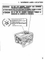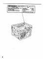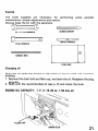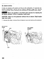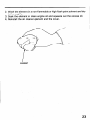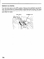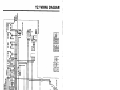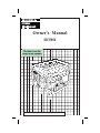
1
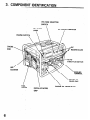
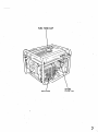
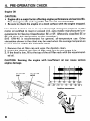
Owner's Manual
EB3500X
©1985 Honda Motor Co., Ltd. — All Rights Reserved
Thank you for purchasing
a Honda generator.
This manual covers operation
and maintenance
of the EB3500X
generators. All information in this publication is based on the latest product
information available at the time of approval for printing.
Honda Motor Co., Ltd. reserves the right to make changes at any time
without notice and without incurring any obligation.
No part of this publication
may be reproduced without
This manual should be considered a permanent
remain with the generator when sold.
Pay special attention
to statements
mm
part of the generator and
preceded by the following
Indicates a strong possibility
life if instructions
are not followed.
CAUTION:
Indicates a possibility
if instructions
are not followed.
written permission.
of severe personal
of personal
words:
injury or loss of
injury or equipment
damage,
NOTE: Gives helpful information.
If a problem should arise, or if you have any questions about the generator,
consult an authorized Honda dealer.
m
The Honda generator is designed to give safe and dependable
service if operated
according
to instructions.
Read and understand
the
Owner’s
Manual before operating
the generator.
Failure to do so could
result in personal injury or equipment
damage.
1
I
/
CONTENTS
CONTENTS
1.
2.
3.
4.
5.
6.
7.
8.
9.
10.
11.
12.
13.
14.
WARNING LABEL LOCATION .................................................
GENERATOR SAFETY ... . .......................................................
COMPONENT IDENTIICATION ................................................
. .................................
PRE-OPERATION CHECK .....................
STARTING THE ENGINE ........................................................
GENERATOR USE .................................................................
STOPPING THE ENGINE ........................................................
.: ...........................................
......................
MAINTENANCE
.: .......
...........................................
TRANSPORTll\jG/STORAGE
TROUBLESHOOTING
............................................................
SPECIFICATIONS ..................................................................
. ...........
WIRING DIAGRAM ....................................................
.................................................
HANGER KIT INSTALLATION
INSTALLATION OF OPTIONAL PARTS .....................................
15. WARRANTY
2
SERVICE
...............................
. ...........................
3
5
6
8
12
15
18
20
28
30
32
33
34
35
36
1. WARNING
LABEL LOCATION
ATTENTIONNEPASUTILISER
DANSUNENDROIT
FERME
A CAUSE
DURISQUE
D’EMPOISONNEMENT
DUGAZ.
ATENClON NO LO USE EN LUGARES
CERRADOS
PORQUE
EL
MONOXIDE
DECARBON0
ESVENENOSO.
//
L
I
STOP ENGINE BtFORf RfFUftlN~
mCONlROLfR
,
OU’IL N’V A.NI
FUIIE NI fSSfNCt
ARRfTfR Lf MOIfUR AVANT Of RfFAIRf
mlNSPfCClONAR
PARA COMBUSllBLf
0 ESCAPE
PARAR MIlTOR ANlfS
Of ECHAR
Lf PIEIN.
DfRRAMAOO
I
3
I
EB350OX
CAUTION
HONDA MOTORCO., LTD. MADE
INJAPANB’
H BE SURE TO FILL CRANKCASE
WITH RECOMMENDED OIL
BEFORE USING.
FOR DETAILED EXPLANATION,
SEE THE OWNER’S MANUAL.
,
c
4
VOLTAGE AC
FREQUENCY
RATED OUTPUT
h&4f$UTPUT
FUEL GASOLINE
12Ol24OV
60Hz
3.OkVA
3.5kVA
10
(PETROL)
2. GENERATOR
m
SAFETY
*
To ensure
safe operation
-
Place the generator
at least 1 m (3 ft) away from buildings
or other
equipment
when operating the generator.
Operate the generator on a level surface.
If the generator is tilted, fuel spillage .may result.
Exhaust gas contains posionous
carbon monoxide.
Never run the generator in an enclosed area.
Be sure to provide adequate ventilation.
Know how to stop the generator quickly and understand
operation of all
the controls. Never permit anyone to operate the generator without proper instructions.
Keep children and pets away from the generator when it is in operation.
Keep away from rotating parts while the generator is running.
The generator is a potential source of electrical shocks when misued; do
not operate with wet hands.
Do not operate the generator in rain or snow and do not let it get wet.
.’
3. COMPONENT
IDENTIFICATION
VOLTAGE SELECTOR
SWITCH
RECERTACLES
THROTTLE SWITCH
FILLER CAP
OIL DRAIN PLUG
VALVE
6
RECOIL STARTER
GRIP
FUEL TANK CAP
.
7
I’
4.
I
I
PRE-OPER&TUON CWECK
Engine
Oil
CAUTION:
l
Engine oil is a major factor affecting engine performance
and service life.
Non-detergent
oiis and vegetable oils are not recommended.
l
Be sure to.check .the engine on a level surface with the engine stopped.
Use Honda 4-stroke oil or an equivalent high detergent premium quality
motor oil certified to meet or exceed U.S. auto-mobile manufacturer’s
requirements for Service Classification SE or SF. (Motoroils classified SE or
SF will show this designation on the container.)
SAE low-40
is recommended for general, all-temperature
use. Other
viscosities shown in the chart may be used when the average temperature
in your area is within the indicated range.
1. Remove the oil filler cap and wipe the dipstick clean.
!Z. Insert the dipstick into.the oil filler neck but do not screw it in.
3. If the level is low, fill to the top of the oil filler neck with the recommended oil.
CAUTION:
Running
engine damage.
OIL FILLER
CAP
the
engine
with
insufficient
oil can
cause
serious
0
20
40°C
OIL FILLER
HOLE
1
-30
-20
-10
Ambient
10
30
,
temperature
LEVEL
8
Fuel
Use automotive gasoline with a pump octane number (9)
of 86
or higher, or a research octane number of 91 or higher (unleaded is preferred to minimize combustion chamber deposits).
Never use an oil/gasoline mixture or dirty gasoline. Avoid getting dirt, dust
or water in the fuel tank.
CAUTION:
Gasoline substitutes
are not recommended;
ful to the fuel system components.
they may be harm-
iam
Gasoline is extremely flammable and explosive under certain conditions.
Refuel in a well ventilated
area with the engine stopped.
l
Do not smoke or allow flames or sparks in the area where the generatior
is refueled or where gasoline is stored.
0 Do not overfill the tank and make sure the filler cap is securely closed
after refueling.
l
Be careful not to spill fuel when refueling. Fuel vapor or spilled fuel may
ignite. If any fuel is spilled, make sure the area is dry before starting the
engine.
l
Fuel tank capacity:
6.0 lit. (12.7
US pt. 10.6 Imp pt)
1. Check the fuel level.
2. If level is low, fill to the shoulder of the fuel filter.
3. After refueling, be sure to tighten the fuel thank cap firmly.
FUEL FILILER CAP
FUEL FILLER UPPER LIMIT
I
I
Gasolines
Containing
Alcohol
If you decide to use a gasoline containing alcohol (“gasohol”),
be sure the
octane rating is at least as high as that recommended by Honda. There are
two types of “gahohol”
that containing ethanol, and that containing
methanol.
Do not use gasohol that contains more than 10% ethanol. Do not use
gasoline containing ,methanol (methyl or wood alcohol) that does not also
contain cosolvents
and corrosion inhibitors for methanol. Never use
gasoline containing more than 5% methanol, even if it has cosolvents and
corrosion inhibitors.
NOTE:
l
Fuel system damage or engine performance problems resulting from the
use of such fuels are not covered under Power Equipment Warranties.
Honda cannot endorse the use of fuels containing methanol since
evidence of their suitability is as yet incomplete.
l
Before purchasing fuel from an unfamiliar station, try to confirm
whether the fuel contains alcohol, and to what percentage. If you notice
any undesirable operating symptoms after using a gasoline that contains
alcohol, or one ttiat you think contains alcohol, switch to a ga?oline that
you know does not contain alcohol.
10
Make sure that the AC circuit breaker is in the OFF position.
The generator
may be hard to start if a load is connected.
AC CIRCUIT BREAKER
11
(’
5. STARTING
I
,
‘THE ENGINE
1. Turn the fuel valve to the 4N position.
FUEL VALVE
2. Pull the choke rod to the CLOSE position.
CHOKE ROD
12
3 Make sure the auto-throttle
’ will be required for Warm
switch is in the OFF
Position,
or more
time
UP.
A;TO-THROTTLE
SWITCH
4. Turn the. engine switth
to the ON Position-
ENGINE SWIT
13
5. Pull the starter grip until compression
is felt, then pull briskly.
NOTE: Do not allow the starter grip to snap back. Return it slowly by
hand.
STARTER GillP
6. Push the choke rdd to the OPEN position as the engine warms up.
7. If auto-throttle
will
be used,
turn the switch
after the engine has warmed up.
14
to the “AUTO”
position
6. GENERATOR
USE
ra!m
To prevent
electrical
shock
from faulty
appliances,
the
generator
should be grounded.
Connect a length of heavy wire between
the ground terminal and the ground source.
CAUTION:
l
Limit operation requiring maximum power (3.5KVA) to 30 minutes. For
continuous
operation,
do not exceed the rated power of 3.0 KVA.
In either case, the total wattage
of all appliances
connected
must be
considered.
l
Do not exceed the current limit specified for any one receptacle.
l
Connection
for emergency
power to household
circuits must be made
by a qualified electrician
and must comply with all applicable laws and
electrical
codes. Improper installation
may result in personal injury or
damage to equipment
or property.
Auto-throttle
system
With the switch in the AUTO position, engine speed is automatically reduced to an idle when all loads are turned off or disconnected. When appliances are turned on or reconnected, the engine resumes the rated speed.
At OFF, the auto-throttle system does not operate.
NOTE:
l
AUTO is recommended to minimize fuel consumption.
l
The auto-throttle system will not respond to electrical loads of less than
1 ampere.
l
The system is not effective for use with appliance that requires only
momentary power. To avoid extended warm-up periods, keep the
switch OFF until the engine reaches operating temperature.
GROUND
TERMINAL
15
AC applications
:
1. Turn the voltage slector switch to either position as required. When the
switch is turned to “12OV ONLY” position, you can use only 12OV AC.
At “12OV/24OV”
position, you can use both 12OV and 240V sources.
2. Switch on the AC Circuit Breaker.
3. Plug in the appliance.
NOTE: This gen&ator is equipped with an AVR (Automatic
Regulator) for stable voltage supply.
Voltage
CAUTION:
Be sure that appliances
do not exceed the rated load for
more than 30 minutes, and never exceed the maximum
load. Substantial overloading
will switch off the circuit breaker. Lesser overloading
will not switch off the circuit breaker’and
will shorten the service life of
the generator.
VOLTAGE SELECTOR
SWITCH
16
AC CIRCUIT BREAKER
I
Oil Alert
System
The Oil Alert system is designed to prevent engine damage caused by an insufficent amount of oil in the crankcase. Before the oil level in the
crankcase can fall below a safe limit, the Oil Alert system will automatically
shut down the engine (the engine switch will remain in the ON position).
If the Oil Alert system shuts down the engine, the Oil Alert lamp will flash
when you operate the starter, and the engine will not run. If this occurs,
add engine oil (p. 8).
OIL ALERT LAMP
, i
7. STOP+lNG
THE EN’GINE
turn the engine switch to the OFF
To stop the engine in an emergency,
position.
I
In normal use:
1. Turn the AC circuit, breaker to the OFF position.
AC CIRCUIT BREAKER
2. Turn the engine switch to the OFF position.
iNGINE SWITCH
18
3. Turn the fuel valve to the OFF position.
FUEL VALVE
19
;
8. MAINTENANCE
The purpose of the maintenance schedule and adjustment
generator in the best operating condition.
Inspect or service as scheduled in the table.
is to keep the
mzm
Shut off the engine before performing
any maintenance.
If the
engine must be run, make sure the area is well ventilated.
The exhaust contains poisonous
carbon monoxide
gas.
CAUTION:
replacement
generator.
Use only genuine HONDA parts or their equivalent.
The use of
parts which are not of equivalent
quality may damage the
Maintenance
REGULAR
Performed
operating
Schedule
SERVI CE PERIOD
inAirz,+c,,-j month
at ev,.art,, IIIuIuW.Iv
hour interval,
whit. rhnvnr
._ _ _.
or
Every
3 months
or
50 Hrs.
First
month
or
Each use
20 Hrs.
Every
6 months
or
100 Hrs.
Every
year
or
300 Hrs
ITEM
Check
Engine
oil
level
I
0
I
Change
I
I
I
0
Check
0
0
Air cleaner
Clean
Sediment
cup
O(1)
Clean
0
Spark
plug
Clean-Readjust
0
Spark
arrester
Clean
0
Valve
clearance
Check-Readjust
I
Fuel tank
Fuel line
NOTE:
20
and strainer
I
OK4
O(2)
I
Clean
Check
(Replace
if necessary)
(1): Service
more frequently
when
(2): These items should be serviced
proper tools and is mechanically
Every
3 years
(2)
used in dusty areas.
by an authorized
Honda dealer, unless the owner
proficient.
See the Honda Shop Manual.
.
nas tne
Tool kit
The tools supplied
are necessary
for performing
maintenance, simple adjustments and repairs.
Always keep the kit with the generator.
s==G
-
10 x 12 mm WRENCH
SCREW
DRIVER
>
HANDLE
WRENCH
1
.
HANDLE
IO
BAR
-
L
TOOL
Changing
periodic
DRIVER
0
c
PLUG
some
-3
BAG
oil
Drain the oil while the engine is still warm to assure rapid and complete
draining.
1. Remove the drain bolt and filler cap, and drain the oil. Retighten the plug
securely.
2. Refill with the recommended oil (see p. >8) and check the level.
ENGINE OIL CAPACITY:
1.1 e (1.16
US qt. i .94 Imp pt)
DRAIN
PLUG
21
Air cleaner
service
A dirty air cleaner will restrict air flow to the carburetor. To prevent carburetor malfunction,
service the air cleaner regularly (page 23). Service
more frequently when operating the generator in extremely dusty areas.
w
air cleaner
Never use gasoline or low flash point solvents
element. A fire or explosion
could result.
CAUTION:
Never
wear may result.
run the generator
j
without
for cleaning
the air cleaner.
the
Rapid engine
1. Unsnap the clips, remove the air cleaner cover and remove the element.
AIR CLEANER
COVER
CLIP
\
/
\
CLIP
22
,:
AIR CLEANER
EL,EMENT
2. Wash the element in a non-flammable or high flash point solvent and dry
it thoroughly.
3. Soak the element in clean engine oil and squeeze out the excess oil.
4. Reinstall the air cleaner element and the cover.
ELEMENT
23
Sediment cup cleaning
Turn the fuel valve to the OFF position. Remove the sedimerit cup and Oring, and wash them’in nonflammable or high flash point solvent. Dry them
thoroughly, and reinbtall securely. Turn the fuel valve to the ON position,
and check for leaks.
FUEL VALVE
SEDIMENT CUP
Spark plug service
Recommended
CAUTION:
spark plug:
BPR5ES (NGK) WlGEPR-U
Never use a spark plug of incorrect
(ND)
heat range.
To ensure proper engine operation, the spark plug must be properly gapped
and free of deposits.
1. Remove the spark plug cap, and use a spark plug wrench to remove the
plug.
mm!
careful
If the engine has been running,
not to touch the muffler.
the muffler
will be very hot. Be
2. Visually inspect the spark plug. Discard it if the insulator is cracked or
chipped. Clean the spark plug with a wire brush if it is to be reused.
3. Measure the plug gap with a feeler gauge. The gap should be 0.7-0.8
mm (0.028-0.031
in).
0.7-0.8
mm
~0.028-0.031
in)
25
4. Check that the spark plug washer is in good condition,
spark plug in by hand to prevent cross-threading.
and thread the
5. After the spark plug is seated, tighten with a spark plug wrench to compress the washer.
NOTE: If installing a new spark plug, tighten l/2 turn after the spark plug
seats to compress the washer. If reinstalling a used spark plug, tighten
l/8- l/4 turn after the spark plug seats to compress the washer.
CAUTION:
tightened
The spark plug must be securely
tightened.
An improperly
spark plug can become very hot and may damage the engine.
”
26
Spark arrester
mml
Allow
maintenance
If the generator has been running,
it to cool before proceeding.
CAUTION:
The spark
maintain its efficiency.
arrester
must
the muffler
be serviced
will be very hot.
at every
100 hours
to
Clean the spark arrester as following:
1. Loosen the screw by the exhaust port of the muffler and remove the
spark arrester.
2. Clean the carbon deposit on the spark arrester with a brush.
3. Install the spark arrester in the reverse order of removal.
/
SPARK ARRESTER
27
9. TRANSPORilhWSTORAGE
m
When transporting
position and keep the engine
spilled fuel may ignite.
ihe engine, turn the fuel valve to the OFF
level to prevent fuel spillage. Fuel vapor or
Before storing the unit for an extended period:
1. Be sure the storage.area is free of excessive humidity and dust.
2. Drain the fuel a: With the fuel valve in the OFF position, remove and empty the sedi.ment cup.
FUEL VALVE
b. Turn the fuel valve to the ON position and drain the gasoline in the
fuel tank into a suitable container.
c. Replace the sediment cup and tighten securely.
28
d. Drain the carburetor by loosening the drain screw. Drain the gasoline
into a suitable container.
3. Change the engine oil.
4. Remove the spark plug and pour about a tablespoon of clean engine oil
into the cylinder. Crank the engine several revolutions to distribute the
oil, then reinstall the spark plug.
5. Pull the starter rope slowly until resistance is felt. Continue pulling until
the notch on the starter pulley aligns with the hole on the recoil starter
(see illustration below). At this point, the intake and exhaust valves are
closed, and this will help to protect the engine from internal corrosion.
Align the notch on the starter pulley
with the hole at the top of recoil starter.
6. Cover the engine to keep out dust.
29
,
,!
10. TROUBLEtiH’OOTlklG
A.
1.
2.
3.
4.
5.
When the engine will not start:
Is the engine switch on?
Does the oil alert’lamp flash when the starter is pulled?
Is there enough fuel?
Are all loads disconnected from the AC receptacles?
Is there a spark at the spark plug?
a. Remove the spark plug cap. Clean any dust from around the spark
plug base, then remove the spark plug.
b. Install the spark plug in the plug cap.
c. Turn the engine switch on.
d. Grounding the side electrode to any engine ground, pull the recoil
starter to see if sparks jump across the gap.
w
Be sure there is no spilled fuel near the spark plug. Spilled
may ignite. Perform:this
test in a well ventilated
area.
/’
e. If there are no.sparks, replace the plug.
f. If the new spark plug does not spark, take the generator
authorized Honda dealer.
‘30
fuel
to an
6. Is gasoline reaching the carburetor?
To check, place a suitable container under the drain, turn the engine
switch on and loosen the drain screw. Fuel should flow out freely.
If OK, try to start the engine according to the instructions.
DRAIN SCREW
7. If the engine still does not start, take the generator to an authorized Honda dealer.
If any fuel is spilled, make sure the area around
and the generator is dry before starting the engine.
Fuel vapor or spilled fuel may ignite.
rmm
the spark plug
B. When the engine starts but stops immediately;
1. Check the oil alert lamp.
If the oil alert lamp flashes when the starter is pulled, check the engine
oil level and fill with the recommended oil.
2. Re-start the engine.
C. No electricity at the AC receptacles:
1. Is the AC circuit breaker on?
2. Check the electrical appliance or equipment
for any defects.
31
11. SPECIFICAT10NS
Dimensions
EB3500X
Model
Power equipment
description
code
Lenght
x Width
EA6
605x495x485mm
(23.8 x 19.5 x 19.1
x Height
62 kg (136.7
Dry weight
Engine
in)
lb)
I
1 Model
Engine
4-stroke,
type
valve,
242 cc (14.8
Displacement
[Bore
x Stroke]
Max.
output
Max.
torque
[73
x 58 rpm
single
I
Cooling
system
Ignition
system
1.7 kg-m
(12.3
230 g/HPh
x 2.3
ft-lb)/2.500
(0.7 Ib/HPh)
air
Transistorized
magneto
Counterclockwise
rotation
Generator
EB3500X
Model
A
Type
Rated
Rated
voltage
frequency
120/24OV
60HZ
Rated
ampere
25/I
Rated
output
AC output
Maximum
32
output
in)]
rpm
Forced
:
cylinder
cuin)
(2.9
8.OHP/3.600
Fuel consumption
1 PTO shaft
overhead
2.5A
3.0KVA
(3OOOW)
3.5KVA
(3OOOW)
rpm
I
-
i
13. #ANGER
8
x
’
/
I(IT INSUALLATION
18 mm FLANGE BOLT (41
HANGER
BRACKET
CAUTION:
l
Position the hanger at the generator’s
balance point, in the middle of the
fuel tank.
l
Fit the end tabs of the -hanger through the bracket slots, and bolt the
brackets to the hanger.
HANGER
/
\
FUEL TANK CAP
34
14. INSTALLATION
4 Wheel
OF OPTIONAL
PARTS
Kit Installation
1. Install the four wheels on the axle shaft.
2. Install the axle assembly on the generator using four bolts and nuts.
WHEEL
STOPPER
NOTE: Install the shaft with wheel stopper facing engine side.
35
,
15. WARRANTY
Owner
I
SERVICE
Satisfaction
Your satisfaction and goodwill are important to your dealer and to us. All
Honda warranty details are explained in the Distributor’s Limited Warranty;
Normally, any problems concerning the product will be handled by your
dealer’s service department. If you have a warranty problem that has not
been handled to your satisfaction,
we suggest you take the following
action:
Normally, any problem concerning the engine will be handled by the
dealer’s service department. If you have a warranty problem that has not
been handled to your satisfaction,
we suggest you take the following
action:
l
Discuss your problem with a member of dealership management. Often
complaints can be quickly resolved at that level. If the problem has
already been reviewed with the Service Manager, contact the owner of
the dealership or the General Manager.
l
If your problem still has not been resolved to your satisfaction, contact
the .Customer Relations Department at the zone office of American
Honda Motor Co:, Inc. in your area. Zone office locations are shown on
the following page. We will need the following information in order to
assist you:
- Your name, address, and telephone number
- Product model and serial number
- Date of purchase
- Dealer name and address
- Nature of the problem
After reviewing all the facts involved, you will be advised of what action
can be taken. Please bear in mind that your problem will likely be resolved
at the dealership, using the dealer’s facilities, equipment, and personnel, so
it is very important that your initial contact be with the dealer.
Your purchase of a Honda generator is greatly appreciated by both your
dealer and American Honda Motor Co., Inc. We want to assist you in every
way possible to assure your complete satisfaction with your purchase.
36
Zone Offce
Locations
NORTHWEST
ZONE OFFICE
(includes
Alaska)
American
Honda Motor Co., Inc.
Customer
Relations
Department
PO Box 30285
Portland,
Oregon 97220
Telephone:
15031 255-1186
MIDWEST
ZONE OFFICE
American
Honda Motor Co.. Inc.
Customer
Relations
Department
PO 90x 22
Greendale,
Wisconsion
53129
Telephone:
(414) 421.9300
\
a Motor Co., Inc.
Customer
Relations
Department
PO Box 420
Gardena,
California
90247
Telephone:
12131 604-2524
SOUTHWEST
ZONE OFFICE
American
Honda Motor Co., Inc.
Customer
Relations
Department
PO Box 5406
Irving, Texas 75062
Telephone:
(2141 258-6883
NORTHEAST
ZONE OFFICE
American
Honda Motor Co., Inc.
Customer
Relations
Department
PO Box 749
Moorestown.
New Jersey 08057
Telephone:
(609) 778-l 100
\
SOUTHEAST
ZONE OFFICE
Iincludes
Puerto Rico1
American
Honda M&r
Co.. Inc.
Customer
Relations
Department
1500 Morrison
Parkway
Alpharetta,
Georgia 30201
Telephone:
I4041 442-2000
37
,
I
MEMO
38
_ .A-‘-
MEMO
39
MEMO
40
. . ‘.
POM53490
31ZB4600
00X31-ZB4-6000
Kinko’s 50.2002.05
Printed on
Recycled Paper
PRINTED IN U.S.A.