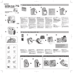
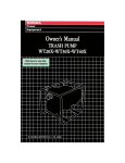
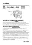
1
The generator is a potential source of electrical shock if misused. Do
not expose the generator to moisture, rain or snow. Do not let the
generator get wet, aqd do not operate it with wet hands.
The engine exhaust from this product
contains chemicals known to the State
of California to cause cancer, birth
defects or other reproductive harm.
Thank you for purchasing a Honda generator.
We want to help you et the best results from your new generator and
on how to
to pperate it safely. -Phis manual contains the information
do that; please read it carefully.
This owner’s manual describes the operation and maintenance of the
Honda Generator: EB2500X
All information
in this publication
is based on the latest product
information available at the time of printing.
Honda Motor Co., Ltd. reserves the right to make changes at any time
without notice and without incurring any obligation.
No part of this publication
may be reproduced
without
written
permission.
This manual should be considered a permanent part of the generator
and should remain with it if it is resold.
Safety Messages
Your safety and the safety of others is very important.
We have
provided
important
safety messages in this manual and on the
generator. Please read these messages carefully.
A safety message alerts you to potential hazards that could hurt you
or others. Each safety message is receded by a safety alert symbol
A and one of three words: DAN CTER, WARNING, or CAUTION.
These mean:
m
follow
You WILL be KILLED or SERIOUSLY
instructions.
HURT if you don’t
-You
follow
CAN be KILLED or SERIOUSLY
HURT if you don’t
instructions.
B
You CAN be HURT if you don’t follow
instructions.
Each message tells you what the hazard is, what can happen,
what you can do to avoid or reduce injury.
Damage Prevention Messages
You will also see other important
word NOTICE.
messages that are preceded
and
by the
This word means:
(y.
don’t follow
ur generator
instructions.
or other property
could be damaged
The purpose of these messa es is to help prevent
generator, other property, or t a e environment.
damage
if you
to your
1
CONTENTS
SAFETY .......................................................................................................
Safety Label Locations ........................................................................
...............................................................................
Safety Information
COMPONENT IDENTIFICATION ...............................................................
CONTROLS ...............................................................................................
Engine Switch .....................................................................................
Recoil Starter ......................................................................................
Fuel Valve ...........................................................................................
Choke Lever ........................................................................................
Circuit Breaker ....................................................................................
Ground Terminal ................................................................................
Oil Alert System .................................................................................
Ground Fault Circuit Interrupter (GFCI) Receptacle ........................
GENERATOR USE ....................................................................................
Connections to a Building’s Electrical System ................................
Ground System ..................................................................................
Special Requirements ........................................................................
..................................................................................
AC Applications
AC Operation ......................................................................................
High Altitude Operation .....................................................................
PRE-OPERATION CHECK ........................................................................
Engine Oil ...........................................................................................
......................................................................
Fuel Recommendation
STARTING THE ENGINE/STOPPING THE ENGINE ...............................
.......................................................................................
MAINTENANCE
The Importance of Maintenance .......................................................
Maintenance Safety ...........................................................................
Emission Control System ..................................................................
Maintenance Schedule ......................................................................
Engine Oil Change .............................................................................
Air Cleaner Service ............................................................................
Fuel Sediment Cup Cleaning ............................................................
Spark Plug Service .............................................................................
.............................................................
Spark Arrester Maintenance
2
4
4
6
8
10
10
10
11
11
12
12
12
14
17
17
17
17
18
19
20
21
21
22
25
26
26
27
28
31
32
33
34
35
37
TRANSPORTING/STORAGE
. ... .. ... .. .. ... ... .. ... .. ... ... .. ... .. ... .. .. ... ..*............... 39
TROUBLESHOOTING
.. .. ... ... .. ... .. ... .. ... ... .. .. ... .. ... ... .. .. ... .. ... ... .. ... .. .. ... .. ... .. . 41
WIRING DIAGRAM ... .. ... ... .. ... ... .. ... .. ... ... .. .. .... .. .. .... .. .. ... .. ... ... .. .. ... ... .. ... .. .. 43
SPECIFICATIONS ... .. ... ... ... .. ... ... .. ... ..... ... ... ... .. ... .. ... ... .. .. ... ... .. ... .. ... ... .. ... ... 44
WARRANTY SERVICE INFORMATION ... ... .. ... ... ... .. ... .. ... ... .. ... .. ... ... .. .. ... 45
INDEX . ... .. ... ... ... .. .... .. .. .... .. ... ... ... .. ... ..... ... ... ... .. ... ... ... .. ... ... .. ... ... .. ... ... .. ... ... . 46
3
SAFETY
SAFETY LABEL LOCATION
These labels warn you of potential
injury.
Read them carefully.
hazards that can cause serious
If a label comes off or becomes hard to read, contact
Generator dealer for a replacement.
*
ch WARN,.,,
USING
THEGWER4lUNIN
your
Honda
NCllfCK tOR SPIllfD flJfL OR VlJfl LfAKS
STOP fR61Wf BffURf RffUfllW.5.
RfPANDUf SUR L’APPARflL.
ARRhfR Lf YOlflJR AVANI Of RflAlRf If PLfIK.
0 ISCAPf.
DONOTUSEINDOORS.
EXHAUST
GASCONTAINS
POISONOUS \
CARBONMONOXIDE.
NE PAS UTILISERDANSUN ENOROIT
FERMEA CAUSEDll
ATTmTioN RISOUED’EMPOISONNEMENT
DU GAZ.
ATENCb()N NO10 USE’ENLUGARES
CERRAOOS
POROUE
EL MONOXIDE
DE CARBON0ES VENENOSO.
9
[I
EL )2500x
HONDA MOTOR CO.,LTD.
MADE
IN JAPAN
@
n BE S
WITH RE
BEFORE
FOR DESEE THE
OCCUPANT’STEST
RECORD
5
SAFETY INFORMATION
Honda generators are designed to give safe and dependable service if
operated according to instructions.
Read and understand this owner’s
manual before operating
your generator.
You can help prevent
accidents by being familiar with your generator’s
controls, and by
observing safe operating procedures.
Operator Responsibility
l Know how to stop the generator
quickly in case of emergency.
l Understand
the use of all generator controls, output receptacles,
and connections.
l Be sure
that anyone who operates the generator receives proper
instruction.
Do not let children
operate the generator
without
parental supervision.
Carbon Monoxide Hazards
l Exhaust
contains poisonous
carbon monoxide,
a colorless and
odorless gas. Breathing exhaust can cause loss of consciousness
and may lead to death.
l If you run the generator
in an area that is confined, or even partially
enclosed, the air you breathe could contain a dangerous amount of
exhaust gas. To keep exhaust gas from building
up, provide
adequate ventilation.
Electric Shock Hazards
l The generator
produces enough electric power to cause a serious
shock or electrocution
if misused.
l Using
a generator or electrical appliance in wet conditions, such as
rain or snow, or near a pool or sprinkler system, or when your hands
are wet, could result in electrocution.
Keep the generator dry.
l If the generator
is stored outdoors, unprotected from the weather,
check the Ground Fault Circuit Interrupter (GFCI) receptacle, and all
other electrical components
on the control panel, before each use.
Moisture or ice can cause a malfunction
or short circuit in electrical
components which could result in electrocution.
l Do not connect
to a building’s electrical system unless an isolation
switch has been installed by a qualified electrician.
6
Fire and Burn Hazards
l The exhaust
system gets hot enough to ignite some materials.
-Keep the generator at least 1 meter (3 feet) away from buildings
and other equipment during operation.
- Do not enclose the generator in any structure.
- Keep flammable materials away from the generator.
l The muffler
becomes very hot during operation and remains hot for
a while after stopping the engine. Be careful not to touch the muffler
while it is hot. Let the engine cool before storing the generator
indoors.
l Gasoline
is extremely flammable
and is explosive
under certain
conditions.
Do not smoke or allow flames or sparks where the
generator is refueled or where gasoline is stored. Refuel in a wellventilated area with the engine stopped.
l Fuel
vapors are extremely
flammable
and may ignite after the
engine has started. Make sure that any spilled fuel has been wiped
up before starting the generator.
7
COMPONENT IDENTIFICATION
ENGINE SWITCH
RECOIL STARTER GRIP
\
OIL DRAIN PLUG
I
ENGINE SERIAL NUMBER
8
FUEL TANK CAP
FUEL METER
PLUG
Record the engine and frame serial numbers for your future reference.
Refer to these serial numbers when ordering parts, and when making
technical or warranty inquiries (see page45 ).
Frame serial number:
Engine serial number:
9
Engine Switch
To start and stop the engine.
Key position:
OFF: To Stop the engine.
ON: To run the engine.
I I I
ENGINE SWITCH
Recoil Starter
To start the engine,
then pull briskly.
pull the starter grip lightly
Do not allow the starter
Return it gently to prevent
10
until resistance
g’rip to snap back against
damage to the starter.
is felt,
the engine.
Fuel Valve
The fuel valve is located between the fuel tank and carburetor. When
the valve lever is in the ON position, fuel is allowed to flow from the
fuel tank to the carburetor.
Be sure to return the lever to the OFF
position after stopping the engine.
VALVE LEVER
Choke Lever
The choke is used to provide an enriched fuel mixture when starting a
cold engine. It can be opened and closed by operating the choke lever
manually. Move the lever to the CLOSE position to enrich the mixture
for cold starting.
c
CHOKE LEVER
CLOSED
11
Circuit Breaker
The circuit breaker will automatically
switch OFF if there is a short
circuit or a significant overload of the generator at the receptacle. If the
circuit breaker is switched OFF automatically,
check that the appliance
is working properly and does not exceed the rated load capacity of the
circuit before switching the circuit breaker ON again.
The circuit breaker may be used to switch the generator power on or
Off.
CIRCUIT BREAKER
/
I
Grownd Terminal
The generator
ground terminal
is connected to the frame of the
generator, the metal non-current-carrying
parts of the generator, and
the ground terminals of each receptacle.
Before using the ground terminal,
consult a qualified
electrician,
electrical inspector or local agency having jurisdiction
for local codes
or ordinances that apply to the intended use of the generator.
GROUN
12
Oil Alert System
The Oil Alert system is designed to prevent engine damage caused by
an insufficient amount of oil in the crankcase. Before the oil level in the
crankcase can fall below a safe limit, the Oil Alert system will
automatically
stop the engine (the engine switch will remain in the ON
position).
If the engine stops and will not restart, check the engine oil level (see
page 21 ) before troubleshooting
in other areas.
UPPER LEVEL
OIL FILLER CAP
OIL FILLER HOLE
OIL FILLER CAP
13
Ground Fault Circuit Interrupter
(GFCI) Receptacle
m
Using the generator in rain, snow or near water
from electric shock. Keep the generator dry.
can lead to death
The 20-ampere, 120-volt duplex receptacle that has TEST and RESET
buttons is protected by a Ground Fault Circuit Interrupter (GFCI) for
protection against the hazards of ground fault currents. Examples of
ground fault current is the current which would flow through a person
who is using an appliance with faulty insulation and, at the same time,
is in contact with an electrical ground such as a plumbing fixture, wet
floor, or earth.
The ground fault circuit interrupter
will not protect against short
circuits or overloads. The circuit breaker in the control panel which
supplies power to the circuit provides that protection
(refer to circuit
breaker on page 12 1.
The ground fault circuit interrupter can be identified by the TEST and
RESET buttons. The duplex receptacle on the GFCI can be tested with
the TEST and RESET buttons.
TEST BUTTON:
To test, depress the “TEST” button (see page 15).
RESET BUTTON:
To restore power, depress the.“RESET” button (see
page 16).
Perform this test monthly to ensure proper operation of the GFCI. If the
generator is stored outdoors, unprotected from the weather, test the
GFCI receptacle before each use. Record your test on the GFCI test
card provided on the fuel tank.
RESET BUlTON
\
14
/
INSPECTION
Perform the tests below to ensure proper operation
of the GFCI.
Record your test on the GFCI test card provided on the generator.
Before each use:
If the generator is stored outdoors, unprotected from the weather, test
the GFCI receptacle before each use as described in the monthly
inspection.
Monthly:
Under normal operating
conditions,
perform the GFCI test monthly.
1. Unplug all appliances from the generator.
2. Start the engine.
3. Turn the circuit breaker ON.
4. Press the TEST BUTTON
-The RESET BUTTON shouldextend
with a click.
-If the RESET BUTTON does not extend, contact
Honda generator dealer.
an authorized
RESET BUTTON
15
5. Press the RESET BUTTON
-The RESET BUTTON should be flush with the base.
-If the RESET BUTTON is not flush with the TEST BUTTON, contact
an authorized Honda generator dealer.
6. When the RESET BUTTON extends during operation:
-Unplug
all appliances from the GFCI protected receptacle.
-Press the RESET BUTTON:
IF THE GFCI CANNOT BE RESET: The GFCI is faulty. Contact an authorized Honda generator dealer.
IF THE GFCI RESETS PROPERLY: Check the appliance or the power
cord.
RESET BUlTON
16
GENERATOR USE
Connections to a Building’s Electrical System
Connections for standby power to a building’s electrical system must
be made by a qualified electrician. The connection
must isolate the
generator
power from utility power, and must comply with all
applicable laws and electrical codes.
Improper connections
to a building’s
electrical system can allow
electrical current from the generator to backfeed into the utility lines.
Such backfeed may electrocute
utility company workers or others
who contact the lines during a power outage. Consult the utility
company or a qualified electrician.
Improper connections
to a building’s
electrical system can allow
electrical current from the utility company to backfeed into the
generator. When utility power is restored, the generator may explode,
burn, or cause fires in the building’s electrical system.
Ground System
Honda portable generators
have a system ground that connects
generator frame components to the ground terminals in the AC output
receptacles. The system ground is not connected to the AC neutral
wire. If the generator is tested by a receptacle tester, it will not show
the same ground circuit condition as for a home receptacle.
Special Requirements
There may be Federal or State Occupational
Safety and Health
Administration
(OSHA) regulations,
local codes, or ordinances that
apply to the intended use of the generator. Please consult a qualified
electrician, electrical inspector, or the local agency having jurisdiction.
l
In some areas, generators are required to be registered with local
utility companies.
l
If the generator
is used at a construction
site, there may be
additional regulations which must be observed.
17
AC Applications
Before connecting
l
l
l
an appliance
or power cord to the generator:
Make sure that it is in good working order. Faulty appliances
power cords can create a potential for electrical shock.
or
If an appliance begins to operate abnormally,
becomes sluggish or
stops suddenly, turn it off immediately.
Disconnect the appliance,
and determine whether the problem is the appliance, or if the rated
load capacity of the generator has been exceeded.
Make sure that the electrical rating of the tool or appliance does not
exceed that of the generator. Never exceed the maximum power
rating of the generator. Power levels between rated and maximum
may be used for no more than 30 minutes.
Substantial
overloading
will open the circuit breaker. Exceeding
time limit for maximum power operation or slightly overloading
generator may not switch the circuit breaker OFF, but will shorten
service life of the generator.
the
the
the
Limit operation requiring maximum power to 30 minutes.
Maximum power is:
2.5 kVA
For continuous operation, do not exceed the rated power.
Rated power is:
2.3 kVA
In either case, the total power requirements
(VA) of all appliances
connected
must be considered.
Appliance
and power
tool
manufacturers
usually list rating information
near the model number
or serial number.
18
AC Operation
1. Start the engine (see page 25 1.
2. Switch ON the AC circuit breaker.
3. Plug in the appliance.
Most motorized appliances require
more than their rated wattage for
startup.
Do not exceed the current limit specified for any one receptacle. If an
overloaded circuit causes the AC circuit breaker or circuit protector to
switch OFF, reduce the electrical load on the circuit, wait a few minutes
and then reset the circuit breaker.
19
l
High Altitude
Operation
At high altitude, the standard carburetor air-fuel mixture will be too
rich. Performance will decrease, and fuel consumption
will increase. A
very rich mixture will also foul the spark plug and cause hard starting.
High altitude performance can be improved by specific modifications
to the carburetor. If you always operate your engine at altitudes above
1,800 meters (6,000 feet), have your dealer perform this carburetor
modification.
Even with carburetor modification,
engine horsepower will decrease
about 3.5% for each 300 meter (1,000 foot) increase in altitude. The effect of altitude on horsepower will be greater than this if no carburetor
modification
is made.
1 NOTICE ]
When the carburetor has been modified for high altitude operation,
the air-fuel mixture will be too lean for low altitude use. Operation at
altitudes below 1,800 meters (6,000 feet) with a modified carburetor
may cause the engine to overheat and result in serious engine
damage. For use at low altitudes,
have your dealer return the
carburetor to original factory specifications.
20
Engine Oil
pi6E-j
Engine oil is a major factor affecting engine performance and service
life. Non-detergent
and 2-stroke engine oils will damage the engine
and are not recommended.
Check the oil level BEFORE
EACH USE with the generator on
a level surface and the engine
stopped.
Use 4-stroke
motor
oil that
meets or exceeds the requirements for API service classification SF or SG. Always check
the API SERVICE label on the oil
container to be sure it includes
the letters SF or SG.
TBMP -”
-30
,’
-20
,20 , 4o , 6o , *’ ,loo’F,
-10
0
10
20
30
40-c
AMBIENT TEMPERATURE
SAE low-30 is recommended
for general, all-temperature
use. Other
viscosities
shown in the chart mav be used when the average
temperature in your area is within the ‘indicated range.
1. Remove the oil filler cap and wipe the dipstick clean.
2.Check the oil level by inserting the dipstick into the filler neck
without screwing it in.
3.lf the level is low, add the recommended
oil to the upper mark on
the dipstick.
UPPER LEVEL
OIL FILLER CAP
OIL FILLER HOLE
OIL FILLER CAP
21
Fuel Recommendation
1. Check the fuel level gauge.
2. Refill the tank if the fuel level is low. Do not fill above the shoulder
the fuel strainer.
l
l
l
l
l
of
Gasoline is extremely
flammable
and is explosive under certain
conditions.
Refuel in a well-ventilated
area with the engine stopped. Do not
smoke or allow flames or sparks in the area where the engine is
refueled or where gasoline is stored.
Do not overfill the fuel tank (there should be no fuel in the filler
neck). After refueling, make sure the tank cap is closed properly and
securely.
Be careful not to spill fuel when refueling. Spilled fuel or fuel vapor
may ignite. If any fuel is spilled, make sure the area is dry before
starting the engine.
Avoid repeated or prolonged
contact with skin or breathing
of
vapor.
KEEP OUT OF REACH OF CHILDREN.
Fuel tank capacity:
11.0 Q (2.91 US gal ,2.42 Imp gal)
Use unleaded gasoline with a pump octane rating of 86 or higher.
This engine is certified to operate on unleaded gasoline.
Unleaded gasoline produces fewer engine and spark plug deposits
and extends exhaust system life.
Never use stale or contaminated
gasoline
Avoid getting dirt or water in the fuel tank.
22
or oil/gasoline
mixture.
Occasionally you may hear light “spark knock” or “pinging”
(metallic
rapping noise) while operating under heavy loads. This IS no cause for
concern.
If spark knock or pin ing occurs at a steady engine speed, under
normal load, change %rands of gasoline. If spark knock or pinging
persists, see an authorized Honda generator dealer.
Running the engine with persistent
engine damage.
spark knock or pinging
can cause
Running the engine with persistent spark knock or pinging is misuse,
and the Distributor’s
Limited Warranty does not cover parts damaged
by misuse.
23
Oxygenated
Fuels
Some conventional
gasolines are being blended with alcohol or an
ether compound.
These gasolines are collectively
referred to as
oxygenated
fuels. To meet clean air standards, some areas of the
United States and Canada use oxygenated
fuels to help reduce
emissions.
If you use an oxygenated fuel, be sure it is unleaded
minimum octane rating requirement.
and meets the
Before using an oxygenated
fuel, try to confirm the fuel’s contents.
Some states/provinces
require this information
to be posted on the
pump.
The following
are the EPA approved
ETHANOL-
MTBE-
percentages
of oxygenates:
(ethyl or grain alcohol) 10% by volume
You may use asoline containing
up to 10% ethanol
by volume.
t! asoline containing
ethanol
may be
marketed under the name “Gasohol”.
(methyl tertiary butyl ether) 15% by volume
Tz;feay
use gasoline containing
up to 15% MTBE by
METHANOL-
(methyl or wood alcohol) 5% by volume
You may use gasoline
containing
up to 5%
methanol
by volume as long as it also contains
cosolvents
and corrosion inhibitors
to protect the
fuel system. Gasoline containing
more than 5%
methanol
by volume may cause starting and/or
performance
problems. It may also damage metal,
rubber, and plastic parts of your fuel system.
If you notice any undesirable operating symptoms,
station or switch to another brand of gasoline.
try another
service
Fuel system damage or performance problems resulting from the use
of an oxygenated
fuel containing
more than the percentages
of
oxygenates mentioned above are not covered under warranty.
24
STARTING THE ENGINE/STOPPING
THE ENGINE
Starting the engine
1. Make sure that the AC circuit breaker is in the OFF position. The
generator may be hard to start if a load is connected.
2. Turn the fuel valve to the ON position.
3. Turn the choke lever to the CLOSE position.
4. Turn the engine switch to the ON position.
5. Pull the starter grip lightly until resistance is felt, then pull briskly.
Do not allow the starter grip to snap back. Return it slowly
6. Turn the choke lever to the OPEN position
Stopping the engine
In an emergency:
l.To stop the engine in an emergency,
OFF position.
by hand.
as the engine warms up.
move the engine switch to the
In normal use:
1. Turn the AC circuit breaker to the OFF position.
2. Move the engine switch to the OFF position.
3. Turn the fuel valve to the OFF position.
25
MAINTENANCE
The Importance
of Maintenance
Good maintenance is essential for safe, economical,
operation. It will also help reduce air pollution.
Improper
operation,
or killed.
and trouble-free
maintenance,
or failure to correct a problem
before
can cause a malfunction
in which you can be seriously hurt
Always follow the inspection and maintenance
schedules in this owner’s manual.
recommendations
and
To help you properly care for your generator, the following
pages
include a maintenance
schedule, routine inspection procedures, and
simple maintenance procedures using basic hand tools. Other service
tasks that are more
difficult,
or require
by professionals and are normally
other qualified mechanic.
special
performed
tools,
are best handled
by a Honda technician
or
The maintenance
schedule applies to normal operating conditions.
If you operate your generator
under severe conditions,
such as
sustained
high-load
or high-temperature
operation,
or use in
unusually wet or dusty conditions, consult your servicing dealer for
recommendations
applicable to your individual needs and use.
Maintenance,
replacement,
or repair of the emission control devices
and systems may be performed by any engine repair establishment
or
individual, using parts that are “certified”
to EPA standards.
26
Maintenance
Safety
Some of the most important safety precautions follow. However, we
cannot warn you of every conceivable
hazard that can arise in
performing
maintenance.
Only you can decide whether or not you
should perform a given task.
Failure to properly follow maintenance
instructions
can cause you to be seriously hurt or killed.
Always follow the procedures
and precautions
and precautions
in the owner’s
manual.
Safety precautions
l
Make sure the engine is off before you begin any maintenance
repairs. This will eliminate several potential hazards:
or
-Carbon monoxide poisoning from engine exhaust.
Be sure there is adequate ventilation
whenever you operate the
engine.
-Burns from hot parts.
Let the engine and exhaust system cool before touching.
-Injury from moving parts.
Do not run the engine unless instructed
l
l
to do so.
Read the instructions before you begin, and make sure you have the
tools and skills required.
To reduce the possibility
of fire or explosion,
be careful when
working around gasoline. Use only a nonflammable
solvent, not
gasoline, to clean parts. Keep cigarettes, sparks, and flames away
from all fuel-related parts.
Remember that your servicing dealer knows your generator
is fully equipped to maintain and repair it.
best and
To ensure the best quality and reliability,
use only new, genuine
Honda parts or their equivalents for repair or replacement.
27
Emission
Control
System
Source of Emissions
The combustion
process
nitrogen, and hydrocarbons.
nitrogen is very important
react to form photochemical
monoxide does not react in
Honda utilizes
the emissions
hydrocarbons.
lean carburetor settings and other systems to reduce
of carbon
monoxide,
oxides
of nitrogen,
and
The U.S. and California
EPA and
produces
carbon monoxide,
oxides of
Control of hydrocarbons
and oxides of
because, under certain conditions,
they
smog when subjected to sunlight. Carbon
the same way, but it is toxic.
California
Clean Air Acts
regulations
written instructions describing
sion control systems.
require
all manufacturers
the operation
and maintenance
to furnish
of emis-
The following
instructions
and procedures must be followed in order
to keep the emissions from your Honda engine within the emission
standards.
Tampering
and Altering
Tampering
emissions
tampering
with or altering the emission control system may increase
beyond the legal limit. Among those acts that constitute
are:
l
l
Removal
systems.
or alteration
Altering
or defeating
mechanism
to cause
parameters.
28
of any part of the intake,
the governor
linkage
the engine to operate
fuel, or exhaust
or speed-adjusting
outside its design
Problems That May Affect Emissions
If you are aware of any of the following symptoms,
inspected and repaired by your servicing dealer.
l
Hard starting
or stalling
l
Rough idle.
l
Misfiring
l
Afterburning
l
Black exhaust smoke or high fuel consumption.
or backfiring
have your engine
after starting.
under load.
(backfiring).
29
Replacement
Parts
The emission control systems on your Honda engine were designed,
built, and certified to conform with EPA and California
emission
regulations.
We recommend
the use of genuine
Honda parts
whenever
you have maintenance
done. These original-design
re.placement parts are manufactured
to the same standards as the
original parts, so you can be confident of their performance.
The use
of replacement parts that are not of the original design and quality
may impair the effectiveness of your emission control system.
A manufacturer
of an aftermarket part assumes the responsibility
that
the part will not adversely
affect emission
performance.
The
manufacturer
or rebuilder of the part must certify that use of the part
will not result in a failure of the engine to comply with emission
regulations.
Maintenance
Follow the maintenance
schedule on page 31. Remember that this
schedule is based on the assumption that your machine will be used
for its designed purpose. Sustained high-load or high-temperature
operation, or use in unusually wet or dusty conditions,
will require
more frequent service.
30
Maintenance
Schedule
at every indicated month
g hour interval,whichever
NOTE:
l Emission
related items.
(1)Service more frequently when used in dusty areas.
(2)These items should be serviced by an authorized Honda generator dealer, unless the
owner has the proper tools and is mechanically
proficient.
See the Honda Shop
Manual.
(3)For professional
commercial
use, log hours of operation
to determine
proper
maintenance intervals.
(4)Check the GFCI before each use if the generator
is stored outside unprotected;
otherwise, test the GFCI monthly and record the test results on the control panel card.
(5)Once each month.
31
Engine Oil Change
Drain the oil while the engine is warm to assure rapid and complete
draining.
I. Remove the drain plug and sealing washer, remove the oil filler cap,
and drain the oil.
2. Reinstall the drain plug and sealing washer. Tighten the plug
securely.
3. Refill with the recommended
oil (see page 21 ) and check the oil
level.
Oil capacity:
0.6 II (0.6 US qt ,0.5 Imp qt)
OIL DRAIN PLUG
OIL DRAIN PLUG
Used motor
the skin for
handle used
your hands
used oil.
oil may cause skin cancer if repeatedly left in contact with
prolonged periods. Although this is unlikely, unless you
oil on a daily basis, it is still advisable to thoroughly
wash
with soap and water as soon as possible after handling
Please dispose of used motor oil and containers in a manner that is
compatible with the environment.
We suggest you take it in a sealed
container
to your local service station or recycling
center for
reclamation.
Do not throw it in the trash, pour it on the ground or
down a drain.
32
Air Cleaner
A dirty air
carburetor
frequently
Service
cleaner will restrict air flow to the carburetor. To prevent
malfunction,
service the air cleaner regularly. Service more
when operating the generator in extremely dusty areas.
Using gasoline or flammable solvent to clean the filter element can
cause a fire or explosion.
Use only soapy water or nonflammable
solvent.
Never run the generator
will result.
without
the air cleaner.
Rapid engine
wear
AIR CLEANER COVER
1. Unsnap the air cleaner cover clips,
remove the air cleaner cover, and
remove the element.
2. Wash the element in a solution of
household
detergent
and warm
water, then rinse thoroughly,
or
wash in nonflammable
or high
flash point solvent.
Allow the
element to dry thoroughly.
CUP
3. Soak the element in clean engine
oil and squeeze out the excess oil.
The engine will smoke during
initial start-up if too much oil is
left in the element.
4. Reinstall the air cleaner
and the cover.
element
AIR CLEANER ELEMENT
ELEMENT
Fuel Sediment Cup Cleaning
The sediment cup prevents dirt or water which may be in the fuel tank
from entering the carburetor. If the engine has not been run for a long
time, the sediment cup should be cleaned.
1. Turn the fuel valve to OFF. Remove the sediment cup and O-ring.
2.Clean the sediment cup and O-ring in nonflammable
or high flash
point solvent.
3. Reinstall the O-ring and sediment cup.
4. Turn the fuel valve ON and check for leaks.
FUEL VALVE
-
SEDIMENT
34
CUP
O-RING
In order to service the spark plug, you will need a spark plug wrench
(commercially
available).
Recommended
spark plugs:
BPRGES (NGK)
W20EPR-U (DENSO)
To ensure proper engine operation,
gapped and free of deposits.
If the engine has been running,
not to touch the muffler.
the spark plug must be properly
the muffler will be very hot. Be careful
1. Remove the spark plug cap.
2. Clean any dirt from around the spark plug base.
3. Use the wrench supplied in the tool kit to remove the spark plug.
PLUG WRENCH
PLUG CAP
4.Visually inspect the spark plug. Discard it if the insulator is cracked
or chipped. Clean the spark plug with a wire brush if it is to be
reused.
5. Measure the plug gap with a feeler gauge.
Correct as necessary by carefully bending the side electrode.
The gap should be:
0.70-0.80 mm (0.028-0.031
in)
0.70-0.80
mm (0.028-0.031
in)
35
6.Check that the spark plug washer is in good condition, and thread
the spark plug in by hand to prevent cross-threading.
7.After the spark plug is seated, tighten with a spark plug wrench to
compress the washer.
-If
installing a new spark plug, tighten l/2 turn after the spark plug
seats to compress the washer. If reinstalling
a used spark plug,
tighten l/8 - l/4 turn after the spark plug seats to compress the
washer.
The spark plug must be securely tightened. An improperly tightened
spark plug can become very hot and could damage the engine.
Never use spark plugs which have an improper heat range. Use only
the recommended
spark plugs or equivalent.
36
Spark Arrester Maintenance
If the generator has been running,
to cool before proceeding.
I
The spark arrester
efficiency.
the muffler will be very hot. Allow it
must be serviced
every 100 hours to maintain
its
1. Remove the five 6 mm bolts to remove the muffler protector.
MUFFLER
PROTECTOR
Five 6 mm bolts
2. Remove the two 8 mm bolts at the exhaust
the muffler stay.
Remove the muffler and spark arrester.
pipe and 8 mm bolt at
RRESTER
MUFFLER
37
3. Use a brush to remove carbon deposits from the spark arrester
screen.
Inspect the spark arrester screen for holes or tears. Replace if necessary.
4. Check the exhaust pipe gasket and replace if damaged.
muffler and the protector.
38
Reinstall the
When transporting
the generator, turn the engine switch and the fuel
valve OFF. Keep the generator level to prevent fuel spillage. Fuel vapor
or spilled fuel may ignite.
m
Contact with a hot engine or exhaust system can cause serious burns
or fires. Let the engine cool before transporting
or storing the
generator.
Take care not to drop or strike the generator
place heavy objects on the generator.
Before storing the unit for an extended
when transporting.
Do not
period:
1. Be sure the storage area’is free of excessive
2. Service according to the table below:
humidity
and dust.
STORAGE TIME
RECOMMENDED SERVICE PROCEDURE TO
PREVENT HARD STARTING
Less than 1 month
No preparation required
1 to 2 months
Fill with fresh gasoline and add gasoline
conditioner*.
Fill with fresh gasoline and add gasoline
2 months to 1 year
conditioner*.
Drain the carburetor float bowl. (page 40).
Drain the fuel sediment cup. (page 34).
Fill with fresh gasoline and add gasoline
conditioner*.
Drain the carburetor float bowl. (page 40).
1 year or more
Drain the fuel sediment cup. (page 34).
Remove the spark plug. Put a tablespoon of
engine oil into the cylinder. Turn the engine
slowly with the pull rope to distribute the oil.
Reinstall the spark plug.
Change the engine oil. (page 32).
After removal from storage, drain the stored
gasoline into a suitable container, and fill
with fresh gasoline before starting.
* Use gasoline conditioners that are formulated to extend storage
life.
Contact your authorized Honda generator dealer for conditioner
recommendations.
39
1.Drain the carburetor
by loosening
gasoline into a suitable container.
the
drain
screw.
Drain
the
Gasoline is extremely
flammable
and is explosive
under certain
conditions. Perform this task in a well-ventilated
area with the engine
stopped. Do not smoke or allow flames or sparks in the area during
this procedure.
DRAIN
2.Change the engine oil (Page 32).
3.Remove the spark plug, and pour about a tablespoon
of clean
engine oil into the cylinder. Crank the engine several revolutions to
distribute the oil, then reinstall the spark plug.
4.Slowly pull the starter grip until resistance IS felt. At this point, the
piston is coming up on its compression
stroke and both the intake
and exhaust valves are closed. Storing the engine in this position
will help to protect it from internal corrosion.
40
TROUBLESHOOTING
When the engine will not start:
Is there fuel in the
tank?
NO
p
Refill the fuel tank.
YES
7
Is there enough
in the engine?
I
YES
oil
Is there a spark
from
the spark
plug?
Add the recommended oil.
NO
Still NO spark
Replace
the
spark plug.
--)
Take the generator
to an authorized
Honda generator
dealer.
To check:
1) Remove
the
spark
plug cap and clean
any dirt from around
Be sure there is no
spilled fuel around the
the spark plug.
spark plug. Spilled fuel 2) Remove
the spark
plug and install the
may ignite.
spark plug in the
plug cap.
YES
3) Set the plug side
electrode
on the
cylinder head.
4) Crank the engine,
sparks should jump
1
across the gap.
Clean the fuel
Is the fuel reaching
NO
sediment cup.
the carburetor?
To check:
1)
Turn off the engine
YES
switch
and loosen
the drain screw.
2) Turn the fuel valve to
If the engine still
ON. Fuel should flow
does not start, take
from the drain when
the generator to an
the fuel
valve
is
authorized
Honda
generator dealer.
turned ON.
I
DRAIN SCREW
No electricity
at the AC receptacles:
Is the AC circuit
ON?
NO ~ Turn
ON.
breaker
the AC circuit
breaker
Is the GFCI in the reset
position?
NO DEFECTS
Check the electrical
piance or equipment
any defects.
I
42
apfor
Take the
m authorized
dealer.
I
generator
to an
Honda generator
I
WIRING DIAGRAM
I AC
-
--
GENERATOR
RECEPTACLES--
BLOCK
43
SPECIFICATIONS
Dimensions
Model
Power product description
Length
Width
Height
Dry weight
EB2500X
EZCP
505 mm (19.9 in)
420 mm (16.5 in)
420 mm (16.5 in)
44.5 kg (98.1 Ibs)
code
Engine
Model
GXIGOKI
4-stroke, overhead valve,
163 cm3 (9.9 cu-in)
168 X 45 mm (2.7 X 1.8
8.5: 1
3,600 r.o.m.
I Forced air
Transistorized
magneto
0.6 !J (0.6 US qt ,0.5 Imp
11.0 !J (2.91 US gal ,2.42
BPRGES (NGK)
1 W20EPRU (DENS01
Engine type
Displacement
Engine speed
I Coolina svstem
Ignition system
Oil capacity
Fuel tank capacity
Spark plug
single cylinder
in)]
qt)
Imp gal)
Geneiator
Model
Type
AC output
Rated voltage
Rated frequency
Rated ampere
Rated output
Maximum output
Tune-w . SDecifications
.
ITEM
Spark plug gap
Valve clearance
Other specifications
NOTE:
Specifications
change without
EB2500X
AG
120v
60 Hz
19.2 A
2.3 kVA
2.5 kVA
SPECIFICATION
MAINTENANCE
0.7-0.8mm(0.028-0.31in)
Refer to page: 35
IN: 0.15+0.02 mm (cold)
See your authorized
EX: 0.20+0.02 mm (cold)
Honda dealer
No other adjustments needed.
may vary
notice.
according
to the types,
and
are subject
to
Honda
power
equipment
dealership
personnel
are trained
professionals.
They should be able to answer any question you may
have. If you encounter a problem that your dealer does not solve to
your satisfaction, please discuss it with the dealership’s management.
The Service Manager or General Manager can help. Almost all
problems are solved in this way.
If you are dissatisfied
with the decision made by the dealership’s
management,
contact
the Honda Power Equipment
Customer
Relations Office. You can write to:
American Honda Motor Co., Inc.
Power Equipment Division
Customer Relations Office
4475 River Green Parkway
Duluth, Georgia 30136-2565
Or telephone:
(770) 497-6400
When you write or call, please give us this information:
l
Model and serial number (see pages 8 and 9 )
l
Name of dealer who sold the generator
l
Name and address of dealer who services your generator
l
Date of purchase
l
Your name, address, and telephone
l
A detailed description
to you
number
of the problem
45
INDEX
COMPONENT IDENTIFICATION ...............................................................
CONTROLS ...............................................................................................
Choke Lever ........................................................................................
Circuit Breaker ....................................................................................
Engine Switch .....................................................................................
Fuel Valve ...........................................................................................
Ground Fault Circuit Interrupter (GFCI) Receptacle ........................
Ground Terminal ................................................................................
Oil Alert System .................................................................................
Recoil Starter ......................................................................................
GENERATOR USE ....................................................................................
..................................................................................
AC Applications
AC Operation ......................................................................................
Connections to a Building’s Electrical System ................................
Ground System ..................................................................................
Special Requirements ........................................................................
.......................................................................................
MAINTENANCE
Air Cleaner Service ............................................................................
Emission Control System ..................................................................
Engine Oil Change .............................................................................
Fuel Sediment Cup Cleaning ............................................................
..............................................................
Importance of Maintenance
Maintenance Safety ...........................................................................
Maintenance Schedule ......................................................................
.............................................................
Spark Arrester Maintenance
Spark Plug Service .............................................................................
PRE-OPERATION CHECK ........................................................................
Engine Oil ...........................................................................................
......................................................................
Fuel Recommendation
SAFETY .......................................................................................................
...............................................................................
Safety information
Label
Locations
........................................................................
Safety
.....................................................................................
SPECIFICATIONS
...................................................................
TRANSPORTING/STORAGE
..............................................................................
TROUBLESHOOTING
WARRANTY SERVICE INFORMATION ..................................................
WIRING DIAGRAM ..................................................................................
46
8
10
11
12
IO
11
14
12
13
IO
17
18
19
17
17
17
26
33
28
32
34
26
27
26
37
35
21
21
22
4
6
4
44
39
41
45
43
MEMO
47
MEMO
48